US5787387A - Harmonic adaptive speech coding method and system - Google Patents
Harmonic adaptive speech coding method and system Download PDFInfo
- Publication number
- US5787387A US5787387A US08/273,069 US27306994A US5787387A US 5787387 A US5787387 A US 5787387A US 27306994 A US27306994 A US 27306994A US 5787387 A US5787387 A US 5787387A
- Authority
- US
- United States
- Prior art keywords
- speech
- segment
- harmonic
- signal
- amplitudes
- Prior art date
- Legal status (The legal status is an assumption and is not a legal conclusion. Google has not performed a legal analysis and makes no representation as to the accuracy of the status listed.)
- Expired - Lifetime
Links
Images


Classifications
-
- G—PHYSICS
- G10—MUSICAL INSTRUMENTS; ACOUSTICS
- G10L—SPEECH ANALYSIS OR SYNTHESIS; SPEECH RECOGNITION; SPEECH OR VOICE PROCESSING; SPEECH OR AUDIO CODING OR DECODING
- G10L25/00—Speech or voice analysis techniques not restricted to a single one of groups G10L15/00 - G10L21/00
- G10L25/90—Pitch determination of speech signals
-
- G—PHYSICS
- G10—MUSICAL INSTRUMENTS; ACOUSTICS
- G10L—SPEECH ANALYSIS OR SYNTHESIS; SPEECH RECOGNITION; SPEECH OR VOICE PROCESSING; SPEECH OR AUDIO CODING OR DECODING
- G10L19/00—Speech or audio signals analysis-synthesis techniques for redundancy reduction, e.g. in vocoders; Coding or decoding of speech or audio signals, using source filter models or psychoacoustic analysis
- G10L19/04—Speech or audio signals analysis-synthesis techniques for redundancy reduction, e.g. in vocoders; Coding or decoding of speech or audio signals, using source filter models or psychoacoustic analysis using predictive techniques
- G10L19/06—Determination or coding of the spectral characteristics, e.g. of the short-term prediction coefficients
-
- G—PHYSICS
- G10—MUSICAL INSTRUMENTS; ACOUSTICS
- G10L—SPEECH ANALYSIS OR SYNTHESIS; SPEECH RECOGNITION; SPEECH OR VOICE PROCESSING; SPEECH OR AUDIO CODING OR DECODING
- G10L19/00—Speech or audio signals analysis-synthesis techniques for redundancy reduction, e.g. in vocoders; Coding or decoding of speech or audio signals, using source filter models or psychoacoustic analysis
- G10L2019/0001—Codebooks
-
- G—PHYSICS
- G10—MUSICAL INSTRUMENTS; ACOUSTICS
- G10L—SPEECH ANALYSIS OR SYNTHESIS; SPEECH RECOGNITION; SPEECH OR VOICE PROCESSING; SPEECH OR AUDIO CODING OR DECODING
- G10L25/00—Speech or voice analysis techniques not restricted to a single one of groups G10L15/00 - G10L21/00
- G10L25/27—Speech or voice analysis techniques not restricted to a single one of groups G10L15/00 - G10L21/00 characterised by the analysis technique
Definitions
- the present invention relates to speech processing and more specifically to a method and system for low bit rate digital encoding and decoding of speech using harmonic analysis and synthesis of the voiced portions and predictive coding of the unvoiced portions of the speech.
- Voiced speech segments which correspond to vowels in a speech signal, typically contribute most to the intelligibility of the speech which is why it is important to accurately represent these segments.
- a set of more than 80 harmonic frequencies (“harmonics") may be measured within a voiced speech segment within a 4 kHz bandwidth.
- harmonics harmonic frequencies
- U.S. Pat. No. 5,054,072 to McAuley describes a method for speech coding which uses a pitch extraction algorithm to model the speech signal by means of a harmonic set of sinusoids that serve as a "perceptual" best fit to the measured sinusoids in a speech segment.
- the system generally attempts to encode the amplitude envelope of the speech signal by interpolating this envelope with a reduced set of harmonics.
- one set of frequencies linearly spaced in the baseband (the low frequency band) and a second set of frequencies logarithmically spaced in the high frequency band are used to represent the actual speech signal by exploiting the correlation between adjacent sinusoids.
- a pitch adaptive amplitude coder is then used to encode the amplitudes of the estimated harmonics.
- the proposed method does not provide accurate estimates, which results in distortions of the synthesized speech.
- the McAuley patent also provides a model for predicting the phases of the high frequency harmonics from the set of coded phases of the baseband harmonics.
- the proposed phase model requires a considerable computational effort and furthermore requires the transmission of additional bits to encode the baseband harmonics phases so that very low bit rates may not be achieved using the system.
- U.S. Pat. No. 4,771,465 describes a speech analyzer and synthesizer system using a sinusoidal encoding and decoding technique for voiced speech segments and noise excitation or multipulse excitation for unvoiced speech segments.
- a fundamental subset of harmonic frequencies is determined by a speech analyzer and is used to derive the parameters of the remaining harmonic frequencies.
- the harmonic amplitudes are determined from linear predictive coding (LPC) coefficients.
- LPC linear predictive coding
- U.S. Pat. Nos. 5,226,108 and 5,216,747 to Hardwick et al. describe an improved pitch estimation method providing sub-integer resolution.
- the quality of the output speech according to the proposed method is improved by increasing the accuracy of the decision as to whether given speech segment is voiced or unvoiced. This decision is made by comparing the energy of the current speech segment to the energy of the preceding segments.
- harmonic frequencies in voiced speech segments are generated using a hybrid approach in which some harmonics are generated in the time domain while the remaining harmonics are generated in the frequency domain. According to the proposed method, a relatively small number of low-frequency harmonics are generated in the time domain and the remaining harmonics are generated in the frequency domain.
- Voiced harmonics generated in the frequency domain are then frequency scaled, transformed into the time domain using a discrete Fourier transform (DFT), linearly interpolated and finally time scaled.
- DFT discrete Fourier transform
- the proposed method generally does not allow accurate estimation of the amplitude and phase information for all harmonics and is computationally expensive.
- U.S. Pat. No. 5,226,084 also to Hardwick et al. describes methods for quantizing speech while preserving its perceptual quality.
- harmonic spectral amplitudes in adjacent speech segments are compared and only the amplitude changes are transmitted to encode the current frame.
- a segment of the speech signal is transformed to the frequency domain to generate a set of spectral amplitudes.
- Prediction spectral amplitudes are then computed using interpolation based on the actual spectral amplitudes of at least one previous speech segment.
- the differences between the actual spectral amplitudes for the current segment and the prediction spectral amplitudes derived from the previous speech segments define prediction residuals which are encoded.
- the method reduces the required bit rate by exploiting the amplitude correlation between the harmonic amplitudes in adjacent speech segments, but is computationally expensive.
- each segment can be classified as either being voiced or unvoiced.
- the continuous input speech signal is digitized and then divided into segments of predetermined length. For each input segment a determination is next made as to whether it is voiced or unvoiced. Dependent on this determination, each time segment is represented in the encoder by a signal vector which contains different information. If the input segment is determined to be unvoiced, the actual speech signal is represented by the elements of a linear predictive coding vector. If the input segment is voiced, the signal is represented by the elements of a harmonic amplitudes vector. Additional control information including the energy of the segment and the fundamental frequency in voiced segments is attached to each predictive coding and harmonic amplitudes vector to form data packets. The ordered sequence of data packets completely represents the input speech signal. Thus, the encoder of the present invention outputs a sequence of data packets which is a low bit-rate digital representation of the input speech.
- the system of the present invention determines whether the segment is voiced or unvoiced using a pitch detector to this end. This determination is made on the basis of the presence of a fundamental frequency in the speech segment which is detected by the pitch detector. If such fundamental frequency is detected, the pitch detector estimates its frequency and outputs a flag indicating that the speech segment is voiced.
- the system of the present invention computes the roots of a characteristic polynomial with coefficients which are the LPC coefficients for the speech segment.
- the computed roots are then quantized and replaced by a quantized vector codebook entry which is representative of the unvoiced time segment.
- the roots of the characteristic polynomial may be quantized using a neural network linear vector quantizer (LVQ1).
- LVQ1 neural network linear vector quantizer
- the speech segment is determined to be voiced, it is passed to a novel super resolution harmonic amplitude estimator which estimates the amplitudes of the harmonic frequencies of the speech segment and outputs a vector of normalized harmonic amplitudes representative of the speech segment.
- a parameter encoder next generates for each time segment of the speech signal a data packet, the elements of which contain information necessary to restore the original signal segment.
- a data packet for an unvoiced speech segment comprises control information, a flag indicating that the segment is unvoiced, the total energy of the segment or the prediction error power, and the elements of the codebook entry defining the roots of the LPC coefficient polynomial.
- a data packet for a voiced speech segment comprises control information, a flag indicating that the segment is voiced, the sum total of the harmonic amplitudes of the segment, the fundamental frequency and a set of estimated normalized harmonic amplitudes.
- the ordered sequence of data packets at the output of the parameter encoder is ready for storage or transmission of the original speech signal.
- a decoder receives the ordered sequence of data packets representing unvoiced and voiced speech signal segments. If the voiced/unvoiced flag indicates that a data packet represents an unvoiced time segment, the transmitted quantized pole vector is used as an index into a pole codebook to determine the LPC coefficients of the unvoiced synthesis (prediction) filter. A gain adjusted white noise generator is then used as the input of the synthesis filter to reconstruct the unvoiced speech segment.
- a novel phase compensated harmonic synthesizer is used to synthesize the voiced speech segment and provide amplitude and phase continuity to the signal of the preceding speech segment. Specifically, using the harmonic amplitudes vector of the voiced data packet, the phase compensated harmonic synthesizer computes the conditions required to insure amplitude and phase continuity between adjacent voiced segments and computes the parameters of the voiced to unvoiced or unvoiced to voiced speech segment transitions. The phases of the harmonic frequencies in a voiced segment are computed from a set of equations defining the phases of the harmonic frequencies in the previous segment.
- the amplitudes of the harmonic frequencies in a voiced segment are determined from a linear interpolation of the received amplitudes of the current and the previous time segments. Continuous boundary conditions between signal transitions at the ends of the segment are finally established before the synthesized signal is passed to a digital-to-analog converter to reproduce the original speech.
- FIG. 1 is a block diagram of the speech processing system of the present invention.
- FIG. 2 is a schematic block diagram of the encoder used in the system of FIG. 1.
- FIG. 3 illustrates the signal sequences of the digitized input signal s(n) which define delayed speech vectors S M (M) and S N-M (N) used in the encoder of FIG. 2.
- FIGS. 4 and 5 are schematic diagrams of the transmitted parameters in an unvoiced and in a voiced data packet, respectively.
- FIG. 6 is a flow diagram of the super resolution harmonic amplitude estimator (SRHAE) used in the encoder in FIG. 2.
- SRHAE super resolution harmonic amplitude estimator
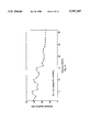
- FIGS. 7A is a graph of the actual and the estimated harmonic amplitudes in a voiced speech segment.
- FIG. 7B illustrates the normalized estimation error in percent % dB for the harmonic amplitudes of the speech segment in FIG. 7A.
- FIG. 8 is a schematic block diagram of the decoder used in the system of FIG. 1.
- FIG. 9 is a flow diagram of the phase compensated harmonic synthesizer in FIG. 8.
- FIGS. 10 A, 10 B illustrate of the harmonics matching problem in the system of the present invention.
- FIG. 11 is a flow diagram of the voiced to voiced speech synthesis algorithm.
- FIG. 12 is a flow diagram of the unvoiced to voiced speech synthesis algorithm.
- FIG. 13 is a flow diagram of the initialization of the system with the parameters of the previous speech segment.
- FIG. 1 is a block diagram of the speech processing system 10 for encoding and decoding speech in accordance with the present invention.
- Analog input speech signal s(t), 15 from an arbitrary voice source is received at encoder 100 for subsequent storage or transmission over a communications channel.
- Encoder 100 digitizes the analog input speech signal 15, divides the digitized speech sequence into speech segments and encodes each segment into a data packet 25 of length I information bits.
- the encoded speech data packets 25 are transmitted over communications channel 101 to decoder 400.
- Decoder 400 receives data packets 25 in their original order to synthesize a digital speech signal which is then passed to a digital-to-analog converter to produce a time delayed analog speech signal 30, denoted s(t-Tm), as explained in detail next.
- FIG. 2 illustrates the main elements of encoder 100 and their interconnections in greater detail.
- Blocks 105, 110 and 115 perform signal pre-processing to facilitate encoding of the input speech.
- analog input speech signal 15 is low pass filtered in block 105 to eliminate frequencies outside the human voice range.
- Low pass filter (LPF) 105 has a cutoff frequency of about 4 KHz which is adequate for the purpose.
- the low pass filtered analog signal is then passed to analog-to-digital converter 110 where it is sampled and quantized to generate a digital signal s(n) suitable for subsequent processing.
- digital input speech signal s(n) is passed through a high pass filter (HPF) 115 which has a cutoff frequency of about 100 Hz in order to eliminate any low frequency noise, such as 60 Hz AC voltage interference.
- HPF high pass filter
- the filtered digital speech signal s(n) is next divided into time segments of a predetermined length in frame segmenters 120 and 125.
- Digital speech signal s(n) is first buffered in frame segmenter 120 which outputs a delayed speech vector S M (M) of length M samples.
- Frame segmenter 120 introduces a time delay of M samples between the current sample of speech signal s(n) and the output speech vector S M (M).
- the length M is selected to be about 160 samples which corresponds to 20 msec of speech at a 8 KHz sampling frequency. This length of the speech segment has been determined to present a good compromise between the requirement to use relatively short segments as to keep the speech signal roughly stationary, and the efficiency of the coding system which generally increases as the delay becomes greater.
- the delay between time segments can be set to other values, such as 50, 100 or 150 samples.
- a second frame segmenter 125 buffers N-M samples into a vector S N-M (N), the last element of which is delayed by N samples from the current speech sample s(n).
- FIG. 3 illustrates the relationship between delayed speech vectors S M (M), S N-M (N) and the digital input speech signal s(n). The function of the delayed vector S N-M (N) will be described in more detail later.
- the step following the segmentation of digital input signal s(n) is to decide whether the current segment is voiced or unvoiced, which decision determines the type of applied signal processing.
- Speech is generally classified as voiced if a fundamental frequency is imported to the air stream by the vocal cords of the speaker. In such case the speech signal is modeled as a superposition of sinusoids which are harmonically related to the fundamental frequency as discussed in more detail next.
- the determination as to whether a speech segment is voiced or unvoiced, and the estimation of the fundamental frequency can be obtained in a variety of ways known in the art as pitch detection algorithms.
- pitch detection block 155 determines whether the speech segment associated with delayed speech vector S M (M) is voiced or unvoiced.
- block 155 employs the pitch detection algorithm described in Y. Medan et al., "Super Resolution Pitch Determination of Speech Signals", IEEE Trans. On Signal Processing, Vol. 39, pp 40-48, June 1991, which is incorporated herein by reference. It will be appreciated that other pitch detection algorithms known in the art can be used as well.
- On output if the segment is determined to be unvoiced, a flag f v/uv is set equal to zero and if the speech segment is voiced flag f v/uv is set equal to one. Additionally, if the speech segment of delayed speech vector S M (M) is voiced, pitch detection block 155 estimates its fundamental frequency F 0 which is output to parameter encoding block 190.
- delayed speech vector S M is windowed in block 160 by a suitable window W to generate windowed speech vector S WM (M) in which the signal discontinuities to adjacent speech segments at both ends of the speech segment are reduced.
- window W may be used to generate windowed speech vector S WM (M) in which the signal discontinuities to adjacent speech segments at both ends of the speech segment are reduced.
- Different windows such as Hamming or Kaiser windows may be used to this end.
- a M-point normalized Hamming window W H (M) is used, the elements of which are scaled to meet the constraint: ##EQU1##
- Wind owed speech vector S WM (M ) is next applied to block 165 for calculating the linear prediction coding (LPC) coefficients which model the human vocal tract.
- LPC linear prediction coding
- the current sample s(n) is modeled using the auto-regressive model:
- a l , . . . , a p are the LPC coefficients and e n is the prediction error.
- the unknown LPC coefficients which minimize the variance of the prediction error are determined by solving a system of linear equations, as known in the art.
- a computationally efficient way to solve for the LPC coefficients is given by the Levinson-Durbin algorithm described for example in S. J. Orphanidis, "Optimum Signal Processing," McGraw Hill, New York, 1988, pp. 202-207, which is hereby incorporated by reference.
- the number P of the preceding speech samples used in the prediction is set equal to 10.
- the LPC coefficients calculated in block 165 are loaded into output vector a op .
- block 165 outputs the prediction error power ⁇ 2 for the speech segment which is used in the decoder of the system to synthesize the unvoiced speech segment.
- vector a op the elements of which are the LPC coefficients, is used to solve for the roots of the homogeneous polynomial equation
- roots can be recognized as the poles of the autoregressive filter modeling the human vocal tract in Eq. (2).
- the roots computed in block 170 are ordered in terms of increasing phase and are loaded into pole vector X p .
- the roots of the polynomial equation may be found by suitable root-finding routines, as described for example in Press et al., "Numerical Recipes, The Art of Scientific Computing," Cambridge University Press, 1986, incorporated herein by reference.
- a computer implementation using an EISPACK set of routines can be used to determine the poles of the polynomial by computing the eigenvalues of the associated characteristic matrix, as used in linear systems theory and described for example in Thomas Kailath, "Linear Systems,” Prentice Hall, Inc., Englewood Cliffs, N.J., 1980.
- the EISPACK mathematical package is described in Smith et al., "Matrix Eigen System Routines--EISPACK Guide," Springer-Verlag, 1976, pp. 28-29. Both publications are incorporated by reference.
- Pole vector X P is next received at vector quantizer block 180 for quantizing it into a codebook entry X VQ .
- the quantized codebook vector X VQ can be determined using neural networks.
- a linear vector quantizing neural network having a Kohonen feature map LVQ1 can be used, as described in T. Kohonen, "Self Organization and Associative Memory,” Series in Information, Sciences, Vol. 8, Springer-Verlag, Berlin-Heidelberg, New York, Tokyo, 1984, 2nd Ed. 1988.
- the use of the quantized polynomial roots to represent the unvoiced speech segment is advantageous in that the dynamic range of the root values is smaller than the corresponding range for encoding the LPC coefficients thus resulting in a coding gain. Furthermore, encoding the roots of the prediction polynomial is advantageous in that the stability of the synthesis filters can be guaranteed by restricting all poles to be less than unity in magnitude. By contrast, relatively small errors in quantizing the LPC coefficients may result in unstable poles of the synthesis filter.
- the elements of the quantized X VQ vector are finally input into parameter encoder 190 to form an unvoiced segment data packet for storage and transmission as described in more detail next.
- processing of the voiced speech segments is executed in blocks 130, 140 and 150.
- frame manager block 130 delayed speech vectors S M (M) and S N-M (N) are concatenated to form speech vector Y N having a total length of N samples.
- S M (M) and S N-M (N) are concatenated to form speech vector Y N having a total length of N samples.
- N-M samples is introduced between adjacent speech segments to provide better continuity at the segment boundaries.
- the digital speech signal vector Y N is modeled as a superposition of H harmonics expressed mathematically as follows: ##EQU2## where A H (h) is the amplitude corresponding to the h-th harmonic, ⁇ h is the phase of the h-th harmonic, F 0 and f s are the fundamental and the sampling frequencies respectively, Z n is unvoiced noise and N is the number of samples in the enlarged speech vector Y N .
- speech vector Y N is multiplied in block 140 by a window W to obtain a windowed speech vector Y WN .
- the specific window used in block 140 is a Hamming or a Kaiser window.
- a N point Kaiser window W K is used, the elements of which are normalized as shown in Eq. (1).
- the window functions used in the Kaiser and Hamming windows of the present invention are described in Oppenheim et al., "Discrete Time Signal Processing," Prentice Hall, Englewood Hills, N.J., 1989.
- the elements of vector Y WN are given by the expression:
- Vector Y WN is received in super resolution harmonic amplitude estimation (SRHAE) block 150 which estimates the amplitudes of the harmonic frequencies on the basis of the fundamental frequency F 0 of the segment obtained in pitch detector 155.
- the estimated amplitudes are combined into harmonic amplitude vector A H which is input to parameter encoding block 190 to form voiced data packets.
- Parameter encoding block 190 receives on input from pitch detector 155 the f v/uv flag which determines whether the current speech segment is voiced or unvoiced, a parameter E which is related to the energy of the segment, the quantized codebook vector X VQ if the segment is unvoiced, or the fundamental frequency F 0 and the harmonic amplitude vector A H if the segment is voiced. Parameter encoding block 190 outputs for each speech segment a data packet which contains all information necessary to reconstruct the speech at the receiving end of the system.
- FIGS. 4 and 5 illustrate the data packets used for storage and transmission of the unvoiced and voiced speech segments in accordance with the present invention.
- each data packet comprises control (synchronization) information and flag f v/uv indicating whether the segment is voiced or unvoiced.
- each package comprises information related to the energy of the speech segment. In an unvoiced data packet this could be the sum of the squares of all speech samples or, alternatively the prediction error power computed in block 165.
- the information indicated as the frame energy in the voiced speech segment in FIG. 5 is preferably the sum of the estimated harmonic amplitudes computed in block 150, as described next.
- the corresponding data packet further comprises the quantized vector X VQ determined in vector quantization block 180.
- the data packet comprises the fundamental frequency F 0 and harmonic amplitude vector A H from block 150, as show in FIG. 5.
- the number of bits in a voiced data package is held constant and may differ from the number of bits in an unvoiced packet which is also constant.
- step 250 the algorithm receives windowed vector Y WN and the f v/uv flag from pitch detector 155.
- step 251 it is checked whether flag f v/uv is equal to one, which indicates voiced speech. If the flag is not equal to one, in step 252 control is transferred to pole calculation block 170 (see FIG. 2). If flag f v/uv is equal to one, step 253 is executed to determine the total number of harmonics H which is set equal to the integer number obtained by dividing the sampling frequency f s by twice the fundamental frequency F 0 .
- a maximum number of harmonics H max is defined and, in a specific embodiment, is set equal to 30.
- step 254 it is determined whether the number of harmonics H computed in step 253 is greater than or equal to the maximum number of harmonics H max and if true, in step 255 the number of harmonics H is set equal to H max .
- step 257 the input windowed vector Y WN is first padded with N zeros to generate a vector Y 2N of length 2N defined as follows: ##EQU3##
- the zero padding operation in step 257 is required in order to obtain the discrete Fourier transform (DFT) of the windowed speech segment in vector Y WN on a more finely divided set of frequencies. It can be appreciated that dependent on the desired frequency separation, a different number of zeros may be appended to windowed speech vector Y WN .
- DFT discrete Fourier transform
- a 2N point discrete Fourier transform of speech vector Y 2N is performed to obtain the frequency domain vector F 2N from which the desired harmonic amplitudes are determined.
- the computation of the DFT is executed using any fast Fourier transform (FFT) algorithm of length 2N.
- FFT fast Fourier transform
- the amplitudes of the harmonic frequencies of the speech segment are calculated next in step 258 in accordance with the formula: ##EQU4## where A H (h,F 0 ) is the estimated amplitude of the h-th harmonic frequency, F 0 is the fundamental frequency of the segment and B is the half bandwidth of the main lobe of the Fourier transform of the window function.
- B is the half bandwidth of the discrete Fourier transform of the Kaiser window used in block 140.
- N the main lobe of a Kaiser window has 11 samples, so that B can be rounded conveniently to 5. Since the windowing operation in block 140 corresponds in the frequency domain to the convolution of the respective transforms of the original speech segment and that of the window function, using all samples within the half bandwidth of the window transform results in an increased accuracy of the estimates for the harmonic amplitudes.
- step 259 the sequence of amplitudes is combined into harmonic amplitude vector A H which is sent to the parameter encoder in step 260.
- FIG. 7A illustrates for comparison the harmonic amplitudes measured in an actual speech segment and the set of harmonic amplitudes estimated using the SRHAE method of the present invention.
- F 0 125.36 Hz.
- a normalized Kaiser window and zero padding as discussed above were also used.
- the percent error between the actual and estimated harmonic amplitudes is plotted in FIG. 7B and indicates very good estimation accuracy.
- the expression used to compute the percent error in FIG. 7B is mathematically expressed as: ##EQU6##
- SRHAE block 150 of the present invention is capable of providing an estimated sequence of harmonic amplitudes A H (h,F 0 ) accurate to within 1000-th of a percent.
- F 0 fundamental frequency
- FIG. 8 is a schematic block diagram of speech decoder 400 in FIG. 1.
- Parameter decoding block 405 receives data packets 25 via communications channel 101.
- data packets 25 correspond to either voiced or unvoiced speech segments as indicated by flag f v/uv .
- data packets 25 comprise a parameter related to the segment energy E; the fundamental frequency F 0 and the estimated harmonic amplitudes vector A H for voiced packets; and the quantized pole vector X VQ for unvoiced speech segments.
- the speech synthesis proceeds in blocks 410 through 460.
- block 410 receives the quantized poles vector X VQ and uses a pole codebook look up table to determine a poles vector X p which corresponds most closely to the received vector X VQ .
- vector X p is converted into a LPC coefficients vector a P of length P.
- Unvoiced synthesis filter 460 is next initialized using the LPC coefficients in vector a P .
- the unvoiced speech segment is synthesized by passing to the synthesis filter 460 the output of white noise generator 450 which output is gain adjusted on the basis of the transmitted prediction error power ⁇ e .
- Digital-to-analog converter 500 completes the process by transforming the unvoiced speech segment to analog speech signal.
- step 500 the synthesis algorithm receives input parameters from the parameter decoding block 405 which includes the f v/uv flag, the fundamental frequency F 0 and the normalized harmonic amplitudes vector A H .
- step 510 it is determined whether the received data packet is voiced or unvoiced as indicated by the value of flag f v/uv . If this value is is not equal to one, in step 515 control is transferred to pole codebook search block 410 for processing of an unvoiced segment.
- step 520 is calculated the number of harmonics H in the segment by dividing the sampling frequency f s of the system by twice the fundamental frequency F 0 for the segment.
- the resulting number of harmonics H is truncated to the value of the closest smaller integer.
- Step 530 compares next the value of the computed number of harmonics H to the maximum number of harmonics H max used in the operation of the system. If H is greater than H max , in step 540 the value of H is set equal to H max . In the following step 550 the elements of the voiced segment synthesis vector V 0 are initialized to zero.
- step 560 the voiced/unvoiced flag f - v/uv of previous segment is examined to determine whether the segment was voiced, in which case control is transferred in step 570 to the voiced-voiced synthesis algorithm. If the previous segment was unvoiced, control is transferred to the unvoiced-voiced synthesis algorithm. Generally, the last sample of the previous speech segment is used as the initial condition in the synthesis of the current segment as to insure amplitude continuity in the signal transition ends.
- voiced speech segments are concatenated subject to the requirement of both amplitude and phase continuity across the segment boundary. This requirement contributes to a significantly reduced distortion and a more natural sound of the synthesized speech.
- the above requirement would be relatively simple to satisfy. However, in practice all three parameters can vary and thus need to be matched separately.
- the algorithm proceeds to match the smallest number H of harmonics common to both segments.
- the remaining harmonics in any segment are considered to have zero amplitudes in the adjacent segment.
- FIG. 10 The problem of harmonics matching is illustrated in FIG. 10 where two sinusoidal signals s - (n) and s(n) having different amplitudes A - and A and fundamental frequencies F - 0 and F 0 have to be matched at the boundary of two adjacent segments of length M.
- the amplitude discontinuity is resolved by means of a linear amplitude interpolation such that at the beginning of the segment the amplitude of the signal S(n) is set equal to A - while at the end it is equal to the harmonic amplitude A.
- this condition is expressed as ##EQU7## where M is the length of the speech segment.
- the condition for phase continuity may be expressed as an equality of the arguments of the sinusoids in Eq. (12) evaluated at the first sample of the current speech segment.
- FIG. 11 is a flow diagram of the voiced-voiced synthesis block of the present invention which implements the above algorithm.
- the system checks whether there is a DC offset V 0 in the previous segment which has to be reduced to zero. If there is no such offset, in steps 620, 622 and 624 the system initializes the elements of the output speech vector to zero. If there is a DC offset, in step 612 the system determines the value of an exponential decay constant ⁇ using the expression: ##EQU10## where V 0 is the DC offset value.
- steps 614, 616 and 618 the constant ⁇ is used to initialize the output speech vector S(m) with an exponential decay function having a time constant equal to ⁇ .
- the elements of speech vector S(m) are given by the expression:
- the system computes in steps 626, 628 and 630 the phase line ⁇ (m) for time samples 0, . . . , M.
- step 640 through 670 the system synthesizes a segment of voiced speech of length M samples which satisfies the conditions for amplitude and phase continuity to the previous voiced speech segment. Specifically, step 640 initializes a loop for the computation of all H harmonic frequencies. In step 650 the system sets up the initial conditions for the amplitude and space continuity for each harmonic frequency as defined in Eqs. (11)-(13) above.
- steps 660, 662 and 664 the system loops through all M samples of the speech segment computing the synthesized voiced segment in step 662 using Eq. (12) and the initial conditions set up in step 650.
- the synthesis signal is computed for all M points of the speech segment and all H harmonic frequencies, following step 670 control is transferred in step 680 to initial conditions block 800.
- FIG. 12 is a flow diagram of the unvoiced-voiced synthesis block which implements the above algorithm.
- the algorithm starts, following an indication that the previous speech segment was unvoiced.
- the vector comprising the harmonic amplitudes of the previous segment is updated to store the harmonic amplitudes of the current voiced segment.
- step 720 a variable sum is set equal to zero and in the following steps 730, 732 and 734 the algorithm loops through the number of harmonic frequencies H adding the estimated amplitudes until the variable Sum contains the sum of all amplitudes of the harmonic frequencies.
- step 740 the system computes the value of the parameter ⁇ after checking whether the sum of all harmonics is not equal to zero.
- steps 750 and 752 the value of ⁇ is adjusted, if .linevert split. ⁇ .linevert split.>1.
- steps 760, 762 and 764 the algorithm loops through all harmonics to determine the initial phase offset ⁇ i for each harmonic frequency.
- the system of the present invention stores in a memory the parameters of the synthesized segment to enable the computation of the amplitude and phase continuity parameters used in the following speech frame.
- the process is illustrated in a flow diagram form in FIG. 13 where in step 800 the amplitudes and phases of the harmonic frequencies of the voiced frame are loaded.
- the system updates the values of the H harmonic amplitudes actually used in the last voiced frame.
- the system sets the values for the parameters of the unused H max -H harmonics to zero.
- the voiced/unvoiced flag f v/uv is set equal to one, indicating the previous frame was voiced.
- the algorithm exits in step 840.
- the method and system of the present invention provide the capability of accurately encoding and synthesizing voiced and unvoiced speech at a minimum bit rate.
- the invention can be used in speech compression for representing speech without using a library of vocal tract models to reconstruct voiced speech.
- the speech analysis used in the encoder of the present invention can be used in speech enhancement for enhancing and coding of speech without the use of a noise reference signal.
- Speech recognition and speaker recognition systems can use the method of the present invention for modeling the phonetic elements of language.
- the speech analysis and synthesis method of this invention provide natural sounding speech which can be used in artificial synthesis of a user's voice.
- the method and system of the present invention may also be used to generate different sound effects. For example, changing the pitch frequency F 0 and/or the harmonic amplitudes in the decoder block will have the perceptual effect of altering the voice personality in the synthesized speech with no other modifications of the system being required. Thus, in some applications while retaining comparable levels of intelligibility of the synthesized speech the decoder block of the present invention may be used to generate different voice personalities.
- a separate type of sound effects may be created if the decoder block uses synthesis frame sizes different from that of the encoder. In such case, the synthesized time segments will be expanded or contracted in time compared to the originals, changing their perceptual quality.
- time warping may also be employed in accordance with the present invention to control the speed of the material presentation, or to obtain a better match between different digital processing systems.
- the input signal of the system may include music, industrial sounds and others.
- harmonic amplitudes corresponding to different tones of a musical instrument may also be stored at the decoder of the system and used independently for music synthesis.
- music synthesis in accordance with the method of the present invention has the benefit of using significantly less memory space as well as more accurately representing the perceptual spectral content of teh audio signal.
Abstract
Description
s(n)=e.sub.n -a.sub.1 s(n-1)-a.sub.2 s(n-2)- . . . -a.sub.p s(n-P)(2)
x.sup.n +a.sub.1 x.sup.n-1 +a.sub.2 x.sup.n-2 + . . . +a.sub.P-1 X.sup.n-(P-1) +a.sub.P =0 (3)
y.sub.WN (n)=W.sub.K (n)·y(n); n=0,1,2, . . . ,N-1(5)
P(k)=F(k). F*(k) (9)
S(m)=V.sub.0 e.sup.-γ·m (15)
S(N)=A.sub.1 (φ.sub.1 +θ.sub.1)+A.sub.2 (φ.sub.2 +θ.sub.2)+ . . . +A.sub.H-1 sin (φ.sub.H-1 +θ.sub.H-1)+ξ. (16)
θ.sub.i =sin.sup.-1 (α)-φ.sub.i ; for i=0, . . . , H-1.(18)
Claims (52)
ξ(h)=(h+1)φ.sup.- (M)+ξ.sup.- (h),
ξ(h)=sin.sup.-1 (α); ##EQU14## where S(M) is the M-th sample of the unvoiced speech segment; A are the harmonic amplitudes for i=0, . . . , H-1; and |α|<1, and φ(m) is evaluated at the M+1 sample.
A(h,m)=A.sup.- (h,0)+m.ΔA(h)/M, for m=0, . . . ,M-1.
ξ(h)=(h+1)φ.sup.- (M)+ξ.sup.- (h),
Priority Applications (3)
| Application Number | Priority Date | Filing Date | Title |
|---|---|---|---|
| US08/273,069 US5787387A (en) | 1994-07-11 | 1994-07-11 | Harmonic adaptive speech coding method and system |
| AU30057/95A AU3005795A (en) | 1994-07-11 | 1995-07-10 | Harmonic adaptive speech coding method and system |
| PCT/US1995/008616 WO1996002050A1 (en) | 1994-07-11 | 1995-07-10 | Harmonic adaptive speech coding method and system |
Applications Claiming Priority (1)
| Application Number | Priority Date | Filing Date | Title |
|---|---|---|---|
| US08/273,069 US5787387A (en) | 1994-07-11 | 1994-07-11 | Harmonic adaptive speech coding method and system |
Publications (1)
| Publication Number | Publication Date |
|---|---|
| US5787387A true US5787387A (en) | 1998-07-28 |
Family
ID=23042415
Family Applications (1)
| Application Number | Title | Priority Date | Filing Date |
|---|---|---|---|
| US08/273,069 Expired - Lifetime US5787387A (en) | 1994-07-11 | 1994-07-11 | Harmonic adaptive speech coding method and system |
Country Status (3)
| Country | Link |
|---|---|
| US (1) | US5787387A (en) |
| AU (1) | AU3005795A (en) |
| WO (1) | WO1996002050A1 (en) |
Cited By (53)
| Publication number | Priority date | Publication date | Assignee | Title |
|---|---|---|---|---|
| WO1999010719A1 (en) * | 1997-08-29 | 1999-03-04 | The Regents Of The University Of California | Method and apparatus for hybrid coding of speech at 4kbps |
| US5924066A (en) * | 1997-09-26 | 1999-07-13 | U S West, Inc. | System and method for classifying a speech signal |
| US5930525A (en) * | 1997-04-30 | 1999-07-27 | Adaptec, Inc. | Method and apparatus for network interface fetching initial and data burst blocks and segmenting blocks and scheduling blocks compatible for transmission over multiple virtual circuits |
| US6014620A (en) * | 1995-06-21 | 2000-01-11 | Telefonaktiebolaget Lm Ericsson | Power spectral density estimation method and apparatus using LPC analysis |
| US6044147A (en) * | 1996-05-16 | 2000-03-28 | British Teledommunications Public Limited Company | Telecommunications system |
| WO2000019414A1 (en) * | 1998-09-26 | 2000-04-06 | Liquid Audio, Inc. | Audio encoding apparatus and methods |
| US6173265B1 (en) * | 1995-12-28 | 2001-01-09 | Olympus Optical Co., Ltd. | Voice recording and/or reproducing method and apparatus for reducing a deterioration of a voice signal due to a change over from one coding device to another coding device |
| WO2001003120A1 (en) * | 1999-07-05 | 2001-01-11 | Matra Nortel Communications | Audio encoding with harmonic components |
| US6185527B1 (en) | 1999-01-19 | 2001-02-06 | International Business Machines Corporation | System and method for automatic audio content analysis for word spotting, indexing, classification and retrieval |
| US6298322B1 (en) | 1999-05-06 | 2001-10-02 | Eric Lindemann | Encoding and synthesis of tonal audio signals using dominant sinusoids and a vector-quantized residual tonal signal |
| US20010033652A1 (en) * | 2000-02-08 | 2001-10-25 | Speech Technology And Applied Research Corporation | Electrolaryngeal speech enhancement for telephony |
| US20010033236A1 (en) * | 2000-04-21 | 2001-10-25 | Ik Multimedia Production S.R.1. | Method for encoding and decoding data streams representing sounds in digital form inside a synthesizer |
| US6311158B1 (en) * | 1999-03-16 | 2001-10-30 | Creative Technology Ltd. | Synthesis of time-domain signals using non-overlapping transforms |
| WO2002003381A1 (en) * | 2000-02-29 | 2002-01-10 | Qualcomm Incorporated | Method and apparatus for tracking the phase of a quasi-periodic signal |
| US20020007268A1 (en) * | 2000-06-20 | 2002-01-17 | Oomen Arnoldus Werner Johannes | Sinusoidal coding |
| US6449592B1 (en) * | 1999-02-26 | 2002-09-10 | Qualcomm Incorporated | Method and apparatus for tracking the phase of a quasi-periodic signal |
| US6470311B1 (en) * | 1999-10-15 | 2002-10-22 | Fonix Corporation | Method and apparatus for determining pitch synchronous frames |
| US20030037982A1 (en) * | 2001-08-23 | 2003-02-27 | Chernoff Adrian B. | Vehicle chassis having programmable operating characteristics and method for using same |
| US6640209B1 (en) * | 1999-02-26 | 2003-10-28 | Qualcomm Incorporated | Closed-loop multimode mixed-domain linear prediction (MDLP) speech coder |
| US6721375B1 (en) * | 1998-11-23 | 2004-04-13 | Robert Bosch Gmbh | Method and device for compensating phase delays |
| US6725190B1 (en) * | 1999-11-02 | 2004-04-20 | International Business Machines Corporation | Method and system for speech reconstruction from speech recognition features, pitch and voicing with resampled basis functions providing reconstruction of the spectral envelope |
| US6782095B1 (en) * | 1997-11-27 | 2004-08-24 | Nortel Networks Limited | Method and apparatus for performing spectral processing in tone detection |
| US6876953B1 (en) * | 2000-04-20 | 2005-04-05 | The United States Of America As Represented By The Secretary Of The Navy | Narrowband signal processor |
| US20050091044A1 (en) * | 2003-10-23 | 2005-04-28 | Nokia Corporation | Method and system for pitch contour quantization in audio coding |
| US20050091041A1 (en) * | 2003-10-23 | 2005-04-28 | Nokia Corporation | Method and system for speech coding |
| US20060064301A1 (en) * | 1999-07-26 | 2006-03-23 | Aguilar Joseph G | Parametric speech codec for representing synthetic speech in the presence of background noise |
| US7039581B1 (en) * | 1999-09-22 | 2006-05-02 | Texas Instruments Incorporated | Hybrid speed coding and system |
| US7219061B1 (en) * | 1999-10-28 | 2007-05-15 | Siemens Aktiengesellschaft | Method for detecting the time sequences of a fundamental frequency of an audio response unit to be synthesized |
| US20070143105A1 (en) * | 2005-12-16 | 2007-06-21 | Keith Braho | Wireless headset and method for robust voice data communication |
| US20070184881A1 (en) * | 2006-02-06 | 2007-08-09 | James Wahl | Headset terminal with speech functionality |
| US20070258385A1 (en) * | 2006-04-25 | 2007-11-08 | Samsung Electronics Co., Ltd. | Apparatus and method for recovering voice packet |
| US7318032B1 (en) * | 2000-06-13 | 2008-01-08 | International Business Machines Corporation | Speaker recognition method based on structured speaker modeling and a “Pickmax” scoring technique |
| US20080052065A1 (en) * | 2006-08-22 | 2008-02-28 | Rohit Kapoor | Time-warping frames of wideband vocoder |
| US20080235034A1 (en) * | 2007-03-23 | 2008-09-25 | Samsung Electronics Co., Ltd. | Method and apparatus for encoding audio signal and method and apparatus for decoding audio signal |
| US20090030690A1 (en) * | 2007-07-25 | 2009-01-29 | Keiichi Yamada | Speech analysis apparatus, speech analysis method and computer program |
| US20090271182A1 (en) * | 2003-12-01 | 2009-10-29 | The Trustees Of Columbia University In The City Of New York | Computer-implemented methods and systems for modeling and recognition of speech |
| USD613267S1 (en) | 2008-09-29 | 2010-04-06 | Vocollect, Inc. | Headset |
| US7773767B2 (en) | 2006-02-06 | 2010-08-10 | Vocollect, Inc. | Headset terminal with rear stability strap |
| US8160287B2 (en) | 2009-05-22 | 2012-04-17 | Vocollect, Inc. | Headset with adjustable headband |
| US20120271632A1 (en) * | 2011-04-25 | 2012-10-25 | Microsoft Corporation | Speaker Identification |
| US8438659B2 (en) | 2009-11-05 | 2013-05-07 | Vocollect, Inc. | Portable computing device and headset interface |
| US20130289981A1 (en) * | 2010-12-23 | 2013-10-31 | France Telecom | Low-delay sound-encoding alternating between predictive encoding and transform encoding |
| US8935156B2 (en) | 1999-01-27 | 2015-01-13 | Dolby International Ab | Enhancing performance of spectral band replication and related high frequency reconstruction coding |
| US9218818B2 (en) | 2001-07-10 | 2015-12-22 | Dolby International Ab | Efficient and scalable parametric stereo coding for low bitrate audio coding applications |
| US9245534B2 (en) | 2000-05-23 | 2016-01-26 | Dolby International Ab | Spectral translation/folding in the subband domain |
| US20160189725A1 (en) * | 2014-12-25 | 2016-06-30 | Yamaha Corporation | Voice Processing Method and Apparatus, and Recording Medium Therefor |
| US9431020B2 (en) | 2001-11-29 | 2016-08-30 | Dolby International Ab | Methods for improving high frequency reconstruction |
| US9542950B2 (en) | 2002-09-18 | 2017-01-10 | Dolby International Ab | Method for reduction of aliasing introduced by spectral envelope adjustment in real-valued filterbanks |
| US9792919B2 (en) | 2001-07-10 | 2017-10-17 | Dolby International Ab | Efficient and scalable parametric stereo coding for low bitrate applications |
| US10388275B2 (en) * | 2017-02-27 | 2019-08-20 | Electronics And Telecommunications Research Institute | Method and apparatus for improving spontaneous speech recognition performance |
| US11410637B2 (en) * | 2016-11-07 | 2022-08-09 | Yamaha Corporation | Voice synthesis method, voice synthesis device, and storage medium |
| US11810545B2 (en) | 2011-05-20 | 2023-11-07 | Vocollect, Inc. | Systems and methods for dynamically improving user intelligibility of synthesized speech in a work environment |
| US11837253B2 (en) | 2016-07-27 | 2023-12-05 | Vocollect, Inc. | Distinguishing user speech from background speech in speech-dense environments |
Families Citing this family (2)
| Publication number | Priority date | Publication date | Assignee | Title |
|---|---|---|---|---|
| JP2778567B2 (en) * | 1995-12-23 | 1998-07-23 | 日本電気株式会社 | Signal encoding apparatus and method |
| WO2016142002A1 (en) * | 2015-03-09 | 2016-09-15 | Fraunhofer-Gesellschaft Zur Foerderung Der Angewandten Forschung E.V. | Audio encoder, audio decoder, method for encoding an audio signal and method for decoding an encoded audio signal |
Citations (50)
| Publication number | Priority date | Publication date | Assignee | Title |
|---|---|---|---|---|
| US3976842A (en) * | 1975-03-10 | 1976-08-24 | Hayward Research, Inc. | Analog rate changer |
| US4015088A (en) * | 1975-10-31 | 1977-03-29 | Bell Telephone Laboratories, Incorporated | Real-time speech analyzer |
| US4020291A (en) * | 1974-08-23 | 1977-04-26 | Victor Company Of Japan, Limited | System for time compression and expansion of audio signals |
| US4076958A (en) * | 1976-09-13 | 1978-02-28 | E-Systems, Inc. | Signal synthesizer spectrum contour scaler |
| US4406001A (en) * | 1980-08-18 | 1983-09-20 | The Variable Speech Control Company ("Vsc") | Time compression/expansion with synchronized individual pitch correction of separate components |
| US4433434A (en) * | 1981-12-28 | 1984-02-21 | Mozer Forrest Shrago | Method and apparatus for time domain compression and synthesis of audible signals |
| US4435832A (en) * | 1979-10-01 | 1984-03-06 | Hitachi, Ltd. | Speech synthesizer having speech time stretch and compression functions |
| US4435831A (en) * | 1981-12-28 | 1984-03-06 | Mozer Forrest Shrago | Method and apparatus for time domain compression and synthesis of unvoiced audible signals |
| US4464784A (en) * | 1981-04-30 | 1984-08-07 | Eventide Clockworks, Inc. | Pitch changer with glitch minimizer |
| US4700391A (en) * | 1983-06-03 | 1987-10-13 | The Variable Speech Control Company ("Vsc") | Method and apparatus for pitch controlled voice signal processing |
| US4771465A (en) * | 1986-09-11 | 1988-09-13 | American Telephone And Telegraph Company, At&T Bell Laboratories | Digital speech sinusoidal vocoder with transmission of only subset of harmonics |
| US4792975A (en) * | 1983-06-03 | 1988-12-20 | The Variable Speech Control ("Vsc") | Digital speech signal processing for pitch change with jump control in accordance with pitch period |
| US4797926A (en) * | 1986-09-11 | 1989-01-10 | American Telephone And Telegraph Company, At&T Bell Laboratories | Digital speech vocoder |
| US4797925A (en) * | 1986-09-26 | 1989-01-10 | Bell Communications Research, Inc. | Method for coding speech at low bit rates |
| US4802221A (en) * | 1986-07-21 | 1989-01-31 | Ncr Corporation | Digital system and method for compressing speech signals for storage and transmission |
| US4821324A (en) * | 1984-12-24 | 1989-04-11 | Nec Corporation | Low bit-rate pattern encoding and decoding capable of reducing an information transmission rate |
| US4839923A (en) * | 1986-12-12 | 1989-06-13 | Motorola, Inc. | Method and apparatus for time companding an analog signal |
| US4852168A (en) * | 1986-11-18 | 1989-07-25 | Sprague Richard P | Compression of stored waveforms for artificial speech |
| US4856068A (en) * | 1985-03-18 | 1989-08-08 | Massachusetts Institute Of Technology | Audio pre-processing methods and apparatus |
| US4864620A (en) * | 1987-12-21 | 1989-09-05 | The Dsp Group, Inc. | Method for performing time-scale modification of speech information or speech signals |
| US4885790A (en) * | 1985-03-18 | 1989-12-05 | Massachusetts Institute Of Technology | Processing of acoustic waveforms |
| US4922537A (en) * | 1987-06-02 | 1990-05-01 | Frederiksen & Shu Laboratories, Inc. | Method and apparatus employing audio frequency offset extraction and floating-point conversion for digitally encoding and decoding high-fidelity audio signals |
| US4937873A (en) * | 1985-03-18 | 1990-06-26 | Massachusetts Institute Of Technology | Computationally efficient sine wave synthesis for acoustic waveform processing |
| US4945565A (en) * | 1984-07-05 | 1990-07-31 | Nec Corporation | Low bit-rate pattern encoding and decoding with a reduced number of excitation pulses |
| US4964166A (en) * | 1988-05-26 | 1990-10-16 | Pacific Communication Science, Inc. | Adaptive transform coder having minimal bit allocation processing |
| US4991213A (en) * | 1988-05-26 | 1991-02-05 | Pacific Communication Sciences, Inc. | Speech specific adaptive transform coder |
| US5001758A (en) * | 1986-04-30 | 1991-03-19 | International Business Machines Corporation | Voice coding process and device for implementing said process |
| US5023910A (en) * | 1988-04-08 | 1991-06-11 | At&T Bell Laboratories | Vector quantization in a harmonic speech coding arrangement |
| US5054072A (en) * | 1987-04-02 | 1991-10-01 | Massachusetts Institute Of Technology | Coding of acoustic waveforms |
| US5056143A (en) * | 1985-03-20 | 1991-10-08 | Nec Corporation | Speech processing system |
| US5073938A (en) * | 1987-04-22 | 1991-12-17 | International Business Machines Corporation | Process for varying speech speed and device for implementing said process |
| US5081681A (en) * | 1989-11-30 | 1992-01-14 | Digital Voice Systems, Inc. | Method and apparatus for phase synthesis for speech processing |
| US5101433A (en) * | 1984-06-28 | 1992-03-31 | King Reginald A | Encoding method |
| US5109417A (en) * | 1989-01-27 | 1992-04-28 | Dolby Laboratories Licensing Corporation | Low bit rate transform coder, decoder, and encoder/decoder for high-quality audio |
| US5142656A (en) * | 1989-01-27 | 1992-08-25 | Dolby Laboratories Licensing Corporation | Low bit rate transform coder, decoder, and encoder/decoder for high-quality audio |
| US5155772A (en) * | 1990-12-11 | 1992-10-13 | Octel Communications Corporations | Data compression system for voice data |
| US5175769A (en) * | 1991-07-23 | 1992-12-29 | Rolm Systems | Method for time-scale modification of signals |
| US5177799A (en) * | 1990-07-03 | 1993-01-05 | Kokusai Electric Co., Ltd. | Speech encoder |
| US5189701A (en) * | 1991-10-25 | 1993-02-23 | Micom Communications Corp. | Voice coder/decoder and methods of coding/decoding |
| US5195166A (en) * | 1990-09-20 | 1993-03-16 | Digital Voice Systems, Inc. | Methods for generating the voiced portion of speech signals |
| US5216747A (en) * | 1990-09-20 | 1993-06-01 | Digital Voice Systems, Inc. | Voiced/unvoiced estimation of an acoustic signal |
| US5226084A (en) * | 1990-12-05 | 1993-07-06 | Digital Voice Systems, Inc. | Methods for speech quantization and error correction |
| US5247579A (en) * | 1990-12-05 | 1993-09-21 | Digital Voice Systems, Inc. | Methods for speech transmission |
| US5303346A (en) * | 1991-08-12 | 1994-04-12 | Alcatel N.V. | Method of coding 32-kb/s audio signals |
| US5311561A (en) * | 1991-03-29 | 1994-05-10 | Sony Corporation | Method and apparatus for compressing a digital input signal with block floating applied to blocks corresponding to fractions of a critical band or to multiple critical bands |
| US5327521A (en) * | 1992-03-02 | 1994-07-05 | The Walt Disney Company | Speech transformation system |
| US5339164A (en) * | 1991-12-24 | 1994-08-16 | Massachusetts Institute Of Technology | Method and apparatus for encoding of data using both vector quantization and runlength encoding and using adaptive runlength encoding |
| US5369724A (en) * | 1992-01-17 | 1994-11-29 | Massachusetts Institute Of Technology | Method and apparatus for encoding, decoding and compression of audio-type data using reference coefficients located within a band of coefficients |
| US5448679A (en) * | 1992-12-30 | 1995-09-05 | International Business Machines Corporation | Method and system for speech data compression and regeneration |
| US5517595A (en) * | 1994-02-08 | 1996-05-14 | At&T Corp. | Decomposition in noise and periodic signal waveforms in waveform interpolation |
-
1994
- 1994-07-11 US US08/273,069 patent/US5787387A/en not_active Expired - Lifetime
-
1995
- 1995-07-10 AU AU30057/95A patent/AU3005795A/en not_active Abandoned
- 1995-07-10 WO PCT/US1995/008616 patent/WO1996002050A1/en active Search and Examination
Patent Citations (52)
| Publication number | Priority date | Publication date | Assignee | Title |
|---|---|---|---|---|
| US4020291A (en) * | 1974-08-23 | 1977-04-26 | Victor Company Of Japan, Limited | System for time compression and expansion of audio signals |
| US3976842A (en) * | 1975-03-10 | 1976-08-24 | Hayward Research, Inc. | Analog rate changer |
| US4015088A (en) * | 1975-10-31 | 1977-03-29 | Bell Telephone Laboratories, Incorporated | Real-time speech analyzer |
| US4076958A (en) * | 1976-09-13 | 1978-02-28 | E-Systems, Inc. | Signal synthesizer spectrum contour scaler |
| US4435832A (en) * | 1979-10-01 | 1984-03-06 | Hitachi, Ltd. | Speech synthesizer having speech time stretch and compression functions |
| US4406001A (en) * | 1980-08-18 | 1983-09-20 | The Variable Speech Control Company ("Vsc") | Time compression/expansion with synchronized individual pitch correction of separate components |
| US4464784A (en) * | 1981-04-30 | 1984-08-07 | Eventide Clockworks, Inc. | Pitch changer with glitch minimizer |
| US4435831A (en) * | 1981-12-28 | 1984-03-06 | Mozer Forrest Shrago | Method and apparatus for time domain compression and synthesis of unvoiced audible signals |
| US4433434A (en) * | 1981-12-28 | 1984-02-21 | Mozer Forrest Shrago | Method and apparatus for time domain compression and synthesis of audible signals |
| US4700391A (en) * | 1983-06-03 | 1987-10-13 | The Variable Speech Control Company ("Vsc") | Method and apparatus for pitch controlled voice signal processing |
| US4792975A (en) * | 1983-06-03 | 1988-12-20 | The Variable Speech Control ("Vsc") | Digital speech signal processing for pitch change with jump control in accordance with pitch period |
| US5101433A (en) * | 1984-06-28 | 1992-03-31 | King Reginald A | Encoding method |
| US4945565A (en) * | 1984-07-05 | 1990-07-31 | Nec Corporation | Low bit-rate pattern encoding and decoding with a reduced number of excitation pulses |
| US4821324A (en) * | 1984-12-24 | 1989-04-11 | Nec Corporation | Low bit-rate pattern encoding and decoding capable of reducing an information transmission rate |
| US4885790A (en) * | 1985-03-18 | 1989-12-05 | Massachusetts Institute Of Technology | Processing of acoustic waveforms |
| US4937873A (en) * | 1985-03-18 | 1990-06-26 | Massachusetts Institute Of Technology | Computationally efficient sine wave synthesis for acoustic waveform processing |
| US4856068A (en) * | 1985-03-18 | 1989-08-08 | Massachusetts Institute Of Technology | Audio pre-processing methods and apparatus |
| US5056143A (en) * | 1985-03-20 | 1991-10-08 | Nec Corporation | Speech processing system |
| US5001758A (en) * | 1986-04-30 | 1991-03-19 | International Business Machines Corporation | Voice coding process and device for implementing said process |
| US4802221A (en) * | 1986-07-21 | 1989-01-31 | Ncr Corporation | Digital system and method for compressing speech signals for storage and transmission |
| US4797926A (en) * | 1986-09-11 | 1989-01-10 | American Telephone And Telegraph Company, At&T Bell Laboratories | Digital speech vocoder |
| US4771465A (en) * | 1986-09-11 | 1988-09-13 | American Telephone And Telegraph Company, At&T Bell Laboratories | Digital speech sinusoidal vocoder with transmission of only subset of harmonics |
| US4797925A (en) * | 1986-09-26 | 1989-01-10 | Bell Communications Research, Inc. | Method for coding speech at low bit rates |
| US4852168A (en) * | 1986-11-18 | 1989-07-25 | Sprague Richard P | Compression of stored waveforms for artificial speech |
| US4839923A (en) * | 1986-12-12 | 1989-06-13 | Motorola, Inc. | Method and apparatus for time companding an analog signal |
| US5054072A (en) * | 1987-04-02 | 1991-10-01 | Massachusetts Institute Of Technology | Coding of acoustic waveforms |
| US5073938A (en) * | 1987-04-22 | 1991-12-17 | International Business Machines Corporation | Process for varying speech speed and device for implementing said process |
| US4922537A (en) * | 1987-06-02 | 1990-05-01 | Frederiksen & Shu Laboratories, Inc. | Method and apparatus employing audio frequency offset extraction and floating-point conversion for digitally encoding and decoding high-fidelity audio signals |
| US4864620A (en) * | 1987-12-21 | 1989-09-05 | The Dsp Group, Inc. | Method for performing time-scale modification of speech information or speech signals |
| US5023910A (en) * | 1988-04-08 | 1991-06-11 | At&T Bell Laboratories | Vector quantization in a harmonic speech coding arrangement |
| US4964166A (en) * | 1988-05-26 | 1990-10-16 | Pacific Communication Science, Inc. | Adaptive transform coder having minimal bit allocation processing |
| US4991213A (en) * | 1988-05-26 | 1991-02-05 | Pacific Communication Sciences, Inc. | Speech specific adaptive transform coder |
| US5109417A (en) * | 1989-01-27 | 1992-04-28 | Dolby Laboratories Licensing Corporation | Low bit rate transform coder, decoder, and encoder/decoder for high-quality audio |
| US5142656A (en) * | 1989-01-27 | 1992-08-25 | Dolby Laboratories Licensing Corporation | Low bit rate transform coder, decoder, and encoder/decoder for high-quality audio |
| US5081681A (en) * | 1989-11-30 | 1992-01-14 | Digital Voice Systems, Inc. | Method and apparatus for phase synthesis for speech processing |
| US5081681B1 (en) * | 1989-11-30 | 1995-08-15 | Digital Voice Systems Inc | Method and apparatus for phase synthesis for speech processing |
| US5177799A (en) * | 1990-07-03 | 1993-01-05 | Kokusai Electric Co., Ltd. | Speech encoder |
| US5226108A (en) * | 1990-09-20 | 1993-07-06 | Digital Voice Systems, Inc. | Processing a speech signal with estimated pitch |
| US5195166A (en) * | 1990-09-20 | 1993-03-16 | Digital Voice Systems, Inc. | Methods for generating the voiced portion of speech signals |
| US5216747A (en) * | 1990-09-20 | 1993-06-01 | Digital Voice Systems, Inc. | Voiced/unvoiced estimation of an acoustic signal |
| US5247579A (en) * | 1990-12-05 | 1993-09-21 | Digital Voice Systems, Inc. | Methods for speech transmission |
| US5226084A (en) * | 1990-12-05 | 1993-07-06 | Digital Voice Systems, Inc. | Methods for speech quantization and error correction |
| US5155772A (en) * | 1990-12-11 | 1992-10-13 | Octel Communications Corporations | Data compression system for voice data |
| US5311561A (en) * | 1991-03-29 | 1994-05-10 | Sony Corporation | Method and apparatus for compressing a digital input signal with block floating applied to blocks corresponding to fractions of a critical band or to multiple critical bands |
| US5175769A (en) * | 1991-07-23 | 1992-12-29 | Rolm Systems | Method for time-scale modification of signals |
| US5303346A (en) * | 1991-08-12 | 1994-04-12 | Alcatel N.V. | Method of coding 32-kb/s audio signals |
| US5189701A (en) * | 1991-10-25 | 1993-02-23 | Micom Communications Corp. | Voice coder/decoder and methods of coding/decoding |
| US5339164A (en) * | 1991-12-24 | 1994-08-16 | Massachusetts Institute Of Technology | Method and apparatus for encoding of data using both vector quantization and runlength encoding and using adaptive runlength encoding |
| US5369724A (en) * | 1992-01-17 | 1994-11-29 | Massachusetts Institute Of Technology | Method and apparatus for encoding, decoding and compression of audio-type data using reference coefficients located within a band of coefficients |
| US5327521A (en) * | 1992-03-02 | 1994-07-05 | The Walt Disney Company | Speech transformation system |
| US5448679A (en) * | 1992-12-30 | 1995-09-05 | International Business Machines Corporation | Method and system for speech data compression and regeneration |
| US5517595A (en) * | 1994-02-08 | 1996-05-14 | At&T Corp. | Decomposition in noise and periodic signal waveforms in waveform interpolation |
Non-Patent Citations (28)
| Title |
|---|
| Almeida et al., "Variable-Frequency Synthesis: An Improved Harmonic Coding Scheme", Proceedings of ICASSP 84, pp. 27.5.1-27.5.4, Mar. 1984. |
| Almeida et al., Variable Frequency Synthesis: An Improved Harmonic Coding Scheme , Proceedings of ICASSP 84, pp. 27.5.1 27.5.4, Mar. 1984. * |
| Conference record of the twenty sixth Asilomar Conference on signals, systems and computers, Kumaresan et al, On accurately tracking the harmonics components parameters in voiced speech segments and subsequent modeling by a transfer function, pp. 472 476, Oct. 1992. * |
| Conference record of the twenty-sixth Asilomar Conference on signals, systems and computers, Kumaresan et al, On accurately tracking the harmonics components' parameters in voiced-speech segments and subsequent modeling by a transfer function, pp. 472-476, Oct. 1992. |
| Griffin et al., "Speech Synthesis from Short-Time Fourier Transform Magnitude and Its Application to Speech Processing", Proceedings of ICASSP 84, pp. 2.4.1-2.4.4, Mar. 1984. |
| Griffin et al., Speech Synthesis from Short Time Fourier Transform Magnitude and Its Application to Speech Processing , Proceedings of ICASSP 84, pp. 2.4.1 2.4.4, Mar. 1984. * |
| Hardwick et al., "A 4.8 KBPS Multi-Band Excitation Speech Coder", Proceedings of ICASSP 88, pp. 374-377, Apr. 1988. |
| Hardwick et al., A 4.8 KBPS Multi Band Excitation Speech Coder , Proceedings of ICASSP 88, pp. 374 377, Apr. 1988. * |
| Marques et al., "A Background for Sinusoid Based Representation of Voiced Speech", Proceedings of ICASSP 86, Tookyo, pp. 1233-1236, Apr. 1986. |
| Marques et al., A Background for Sinusoid Based Representation of Voiced Speech , Proceedings of ICASSP 86, Tookyo, pp. 1233 1236, Apr. 1986. * |
| McAulay et al., "Computationally Efficient Sine-wave Synthesis and its Application to Sinusoidal Transform Coding", Proceedings of ICASSP 88, pp. 370-373, Apr. 1988. |
| McAulay et al., "Magnitude-Only Reconstruction Using A Sinusoidal Speech Model", Proceedings of ICASSP 84, pp. 27.6.1-27.6.4, Mar. 1984. |
| McAulay et al., "Mid-Rate Coding Based on a Sinusoidal Representation of Speech", Proceedings of ICASSP 85, pp. 945-948, Mar. 1985. |
| McAulay et al., "Phase Modelling and its Application Sinusoidal Transform Coding", Proceedings of ICASSP 86, pp. 1713-1715., Apr. 1986. |
| McAulay et al., Computationally Efficient Sine wave Synthesis and its Application to Sinusoidal Transform Coding , Proceedings of ICASSP 88, pp. 370 373, Apr. 1988. * |
| McAulay et al., Magnitude Only Reconstruction Using A Sinusoidal Speech Model , Proceedings of ICASSP 84, pp. 27.6.1 27.6.4, Mar. 1984. * |
| McAulay et al., Mid Rate Coding Based on a Sinusoidal Representation of Speech , Proceedings of ICASSP 85, pp. 945 948, Mar. 1985. * |
| McAulay et al., Phase Modelling and its Application Sinusoidal Transform Coding , Proceedings of ICASSP 86, pp. 1713 1715., Apr. 1986. * |
| Medan et al., "Super Resolution Pitch Determination of Speech Signals", IEEE Trans. On Signal Processing vol. 39, 1991, pp. 40-48., Jan. 1991. |
| Medan et al., Super Resolution Pitch Determination of Speech Signals , IEEE Trans. On Signal Processing vol. 39, 1991, pp. 40 48., Jan. 1991. * |
| Procedings of 1994 IEEE Region 10 s Ninth Annual International COnference; Qiu et al, A fundamental frequency detector of speech signals based on short time Fourier transform , pp. 526 530 vol. 1, Aug. 1994. * |
| Procedings of 1994 IEEE Region 10's Ninth Annual International COnference; Qiu et al, "A fundamental frequency detector of speech signals based on short time Fourier transform", pp. 526-530 vol. 1, Aug. 1994. |
| S.J. Orphanidis, "Optimum Signal Processing", McGraw-Hill, New York, 1988, pp. 202-207. |
| S.J. Orphanidis, Optimum Signal Processing , McGraw Hill, New York, 1988, pp. 202 207. * |
| Thompson, David L., "Parametric Models of the Magnitude/Phase Spectrum for Harmonic Speech Coding", Proceedings of ICASSP 88, New York, pp. 378-381, Apr. 1988. |
| Thompson, David L., Parametric Models of the Magnitude/Phase Spectrum for Harmonic Speech Coding , Proceedings of ICASSP 88, New York, pp. 378 381, Apr. 1988. * |
| Trancoso et al., "A Study on the Relationships Between Stochastic and Harmonic Coding", Proceedings of ICASSP 86, Tokyo, pp. 1709-1712, Apr. 1986. |
| Trancoso et al., A Study on the Relationships Between Stochastic and Harmonic Coding , Proceedings of ICASSP 86, Tokyo, pp. 1709 1712, Apr. 1986. * |
Cited By (106)
| Publication number | Priority date | Publication date | Assignee | Title |
|---|---|---|---|---|
| US6014620A (en) * | 1995-06-21 | 2000-01-11 | Telefonaktiebolaget Lm Ericsson | Power spectral density estimation method and apparatus using LPC analysis |
| US6173265B1 (en) * | 1995-12-28 | 2001-01-09 | Olympus Optical Co., Ltd. | Voice recording and/or reproducing method and apparatus for reducing a deterioration of a voice signal due to a change over from one coding device to another coding device |
| US6044147A (en) * | 1996-05-16 | 2000-03-28 | British Teledommunications Public Limited Company | Telecommunications system |
| US5930525A (en) * | 1997-04-30 | 1999-07-27 | Adaptec, Inc. | Method and apparatus for network interface fetching initial and data burst blocks and segmenting blocks and scheduling blocks compatible for transmission over multiple virtual circuits |
| US6233550B1 (en) | 1997-08-29 | 2001-05-15 | The Regents Of The University Of California | Method and apparatus for hybrid coding of speech at 4kbps |
| US6475245B2 (en) | 1997-08-29 | 2002-11-05 | The Regents Of The University Of California | Method and apparatus for hybrid coding of speech at 4KBPS having phase alignment between mode-switched frames |
| WO1999010719A1 (en) * | 1997-08-29 | 1999-03-04 | The Regents Of The University Of California | Method and apparatus for hybrid coding of speech at 4kbps |
| US5924066A (en) * | 1997-09-26 | 1999-07-13 | U S West, Inc. | System and method for classifying a speech signal |
| US6782095B1 (en) * | 1997-11-27 | 2004-08-24 | Nortel Networks Limited | Method and apparatus for performing spectral processing in tone detection |
| US6266644B1 (en) | 1998-09-26 | 2001-07-24 | Liquid Audio, Inc. | Audio encoding apparatus and methods |
| WO2000019414A1 (en) * | 1998-09-26 | 2000-04-06 | Liquid Audio, Inc. | Audio encoding apparatus and methods |
| US6721375B1 (en) * | 1998-11-23 | 2004-04-13 | Robert Bosch Gmbh | Method and device for compensating phase delays |
| US6185527B1 (en) | 1999-01-19 | 2001-02-06 | International Business Machines Corporation | System and method for automatic audio content analysis for word spotting, indexing, classification and retrieval |
| US9245533B2 (en) | 1999-01-27 | 2016-01-26 | Dolby International Ab | Enhancing performance of spectral band replication and related high frequency reconstruction coding |
| US8935156B2 (en) | 1999-01-27 | 2015-01-13 | Dolby International Ab | Enhancing performance of spectral band replication and related high frequency reconstruction coding |
| US6449592B1 (en) * | 1999-02-26 | 2002-09-10 | Qualcomm Incorporated | Method and apparatus for tracking the phase of a quasi-periodic signal |
| US6640209B1 (en) * | 1999-02-26 | 2003-10-28 | Qualcomm Incorporated | Closed-loop multimode mixed-domain linear prediction (MDLP) speech coder |
| US6311158B1 (en) * | 1999-03-16 | 2001-10-30 | Creative Technology Ltd. | Synthesis of time-domain signals using non-overlapping transforms |
| US6298322B1 (en) | 1999-05-06 | 2001-10-02 | Eric Lindemann | Encoding and synthesis of tonal audio signals using dominant sinusoids and a vector-quantized residual tonal signal |
| FR2796190A1 (en) * | 1999-07-05 | 2001-01-12 | Matra Nortel Communications | AUDIO CODING METHOD AND DEVICE |
| WO2001003120A1 (en) * | 1999-07-05 | 2001-01-11 | Matra Nortel Communications | Audio encoding with harmonic components |
| US20060064301A1 (en) * | 1999-07-26 | 2006-03-23 | Aguilar Joseph G | Parametric speech codec for representing synthetic speech in the presence of background noise |
| US7092881B1 (en) | 1999-07-26 | 2006-08-15 | Lucent Technologies Inc. | Parametric speech codec for representing synthetic speech in the presence of background noise |
| US7257535B2 (en) | 1999-07-26 | 2007-08-14 | Lucent Technologies Inc. | Parametric speech codec for representing synthetic speech in the presence of background noise |
| US7039581B1 (en) * | 1999-09-22 | 2006-05-02 | Texas Instruments Incorporated | Hybrid speed coding and system |
| US6470311B1 (en) * | 1999-10-15 | 2002-10-22 | Fonix Corporation | Method and apparatus for determining pitch synchronous frames |
| US7219061B1 (en) * | 1999-10-28 | 2007-05-15 | Siemens Aktiengesellschaft | Method for detecting the time sequences of a fundamental frequency of an audio response unit to be synthesized |
| US6725190B1 (en) * | 1999-11-02 | 2004-04-20 | International Business Machines Corporation | Method and system for speech reconstruction from speech recognition features, pitch and voicing with resampled basis functions providing reconstruction of the spectral envelope |
| US6975984B2 (en) | 2000-02-08 | 2005-12-13 | Speech Technology And Applied Research Corporation | Electrolaryngeal speech enhancement for telephony |
| US20010033652A1 (en) * | 2000-02-08 | 2001-10-25 | Speech Technology And Applied Research Corporation | Electrolaryngeal speech enhancement for telephony |
| WO2002003381A1 (en) * | 2000-02-29 | 2002-01-10 | Qualcomm Incorporated | Method and apparatus for tracking the phase of a quasi-periodic signal |
| KR100711040B1 (en) | 2000-02-29 | 2007-04-24 | 퀄컴 인코포레이티드 | Method and apparatus for tracking the phase of a quasi-periodic signal |
| US6876953B1 (en) * | 2000-04-20 | 2005-04-05 | The United States Of America As Represented By The Secretary Of The Navy | Narrowband signal processor |
| US20010033236A1 (en) * | 2000-04-21 | 2001-10-25 | Ik Multimedia Production S.R.1. | Method for encoding and decoding data streams representing sounds in digital form inside a synthesizer |
| US9697841B2 (en) | 2000-05-23 | 2017-07-04 | Dolby International Ab | Spectral translation/folding in the subband domain |
| US9786290B2 (en) | 2000-05-23 | 2017-10-10 | Dolby International Ab | Spectral translation/folding in the subband domain |
| US9245534B2 (en) | 2000-05-23 | 2016-01-26 | Dolby International Ab | Spectral translation/folding in the subband domain |
| US10699724B2 (en) | 2000-05-23 | 2020-06-30 | Dolby International Ab | Spectral translation/folding in the subband domain |
| US9691399B1 (en) | 2000-05-23 | 2017-06-27 | Dolby International Ab | Spectral translation/folding in the subband domain |
| US10311882B2 (en) | 2000-05-23 | 2019-06-04 | Dolby International Ab | Spectral translation/folding in the subband domain |
| US9691400B1 (en) | 2000-05-23 | 2017-06-27 | Dolby International Ab | Spectral translation/folding in the subband domain |
| US10008213B2 (en) | 2000-05-23 | 2018-06-26 | Dolby International Ab | Spectral translation/folding in the subband domain |
| US9691403B1 (en) | 2000-05-23 | 2017-06-27 | Dolby International Ab | Spectral translation/folding in the subband domain |
| US9691401B1 (en) | 2000-05-23 | 2017-06-27 | Dolby International Ab | Spectral translation/folding in the subband domain |
| US9691402B1 (en) | 2000-05-23 | 2017-06-27 | Dolby International Ab | Spectral translation/folding in the subband domain |
| US7318032B1 (en) * | 2000-06-13 | 2008-01-08 | International Business Machines Corporation | Speaker recognition method based on structured speaker modeling and a “Pickmax” scoring technique |
| US7739106B2 (en) * | 2000-06-20 | 2010-06-15 | Koninklijke Philips Electronics N.V. | Sinusoidal coding including a phase jitter parameter |
| US20020007268A1 (en) * | 2000-06-20 | 2002-01-17 | Oomen Arnoldus Werner Johannes | Sinusoidal coding |
| US9792919B2 (en) | 2001-07-10 | 2017-10-17 | Dolby International Ab | Efficient and scalable parametric stereo coding for low bitrate applications |
| US9799340B2 (en) | 2001-07-10 | 2017-10-24 | Dolby International Ab | Efficient and scalable parametric stereo coding for low bitrate audio coding applications |
| US9218818B2 (en) | 2001-07-10 | 2015-12-22 | Dolby International Ab | Efficient and scalable parametric stereo coding for low bitrate audio coding applications |
| US9799341B2 (en) | 2001-07-10 | 2017-10-24 | Dolby International Ab | Efficient and scalable parametric stereo coding for low bitrate applications |
| US9865271B2 (en) | 2001-07-10 | 2018-01-09 | Dolby International Ab | Efficient and scalable parametric stereo coding for low bitrate applications |
| US10297261B2 (en) | 2001-07-10 | 2019-05-21 | Dolby International Ab | Efficient and scalable parametric stereo coding for low bitrate audio coding applications |
| US10540982B2 (en) | 2001-07-10 | 2020-01-21 | Dolby International Ab | Efficient and scalable parametric stereo coding for low bitrate audio coding applications |
| US10902859B2 (en) | 2001-07-10 | 2021-01-26 | Dolby International Ab | Efficient and scalable parametric stereo coding for low bitrate audio coding applications |
| US20030037982A1 (en) * | 2001-08-23 | 2003-02-27 | Chernoff Adrian B. | Vehicle chassis having programmable operating characteristics and method for using same |
| US9431020B2 (en) | 2001-11-29 | 2016-08-30 | Dolby International Ab | Methods for improving high frequency reconstruction |
| US11238876B2 (en) | 2001-11-29 | 2022-02-01 | Dolby International Ab | Methods for improving high frequency reconstruction |
| US10403295B2 (en) | 2001-11-29 | 2019-09-03 | Dolby International Ab | Methods for improving high frequency reconstruction |
| US9818418B2 (en) | 2001-11-29 | 2017-11-14 | Dolby International Ab | High frequency regeneration of an audio signal with synthetic sinusoid addition |
| US9812142B2 (en) | 2001-11-29 | 2017-11-07 | Dolby International Ab | High frequency regeneration of an audio signal with synthetic sinusoid addition |
| US9792923B2 (en) | 2001-11-29 | 2017-10-17 | Dolby International Ab | High frequency regeneration of an audio signal with synthetic sinusoid addition |
| US9779746B2 (en) | 2001-11-29 | 2017-10-03 | Dolby International Ab | High frequency regeneration of an audio signal with synthetic sinusoid addition |
| US9761237B2 (en) | 2001-11-29 | 2017-09-12 | Dolby International Ab | High frequency regeneration of an audio signal with synthetic sinusoid addition |
| US9761236B2 (en) | 2001-11-29 | 2017-09-12 | Dolby International Ab | High frequency regeneration of an audio signal with synthetic sinusoid addition |
| US9761234B2 (en) | 2001-11-29 | 2017-09-12 | Dolby International Ab | High frequency regeneration of an audio signal with synthetic sinusoid addition |
| US10157623B2 (en) | 2002-09-18 | 2018-12-18 | Dolby International Ab | Method for reduction of aliasing introduced by spectral envelope adjustment in real-valued filterbanks |
| US9542950B2 (en) | 2002-09-18 | 2017-01-10 | Dolby International Ab | Method for reduction of aliasing introduced by spectral envelope adjustment in real-valued filterbanks |
| US20050091044A1 (en) * | 2003-10-23 | 2005-04-28 | Nokia Corporation | Method and system for pitch contour quantization in audio coding |
| US20080275695A1 (en) * | 2003-10-23 | 2008-11-06 | Nokia Corporation | Method and system for pitch contour quantization in audio coding |
| US20050091041A1 (en) * | 2003-10-23 | 2005-04-28 | Nokia Corporation | Method and system for speech coding |
| US8380496B2 (en) | 2003-10-23 | 2013-02-19 | Nokia Corporation | Method and system for pitch contour quantization in audio coding |
| US7672838B1 (en) | 2003-12-01 | 2010-03-02 | The Trustees Of Columbia University In The City Of New York | Systems and methods for speech recognition using frequency domain linear prediction polynomials to form temporal and spectral envelopes from frequency domain representations of signals |
| US20090271182A1 (en) * | 2003-12-01 | 2009-10-29 | The Trustees Of Columbia University In The City Of New York | Computer-implemented methods and systems for modeling and recognition of speech |
| US7636659B1 (en) * | 2003-12-01 | 2009-12-22 | The Trustees Of Columbia University In The City Of New York | Computer-implemented methods and systems for modeling and recognition of speech |
| US8417185B2 (en) | 2005-12-16 | 2013-04-09 | Vocollect, Inc. | Wireless headset and method for robust voice data communication |
| US20070143105A1 (en) * | 2005-12-16 | 2007-06-21 | Keith Braho | Wireless headset and method for robust voice data communication |
| US7885419B2 (en) | 2006-02-06 | 2011-02-08 | Vocollect, Inc. | Headset terminal with speech functionality |
| US7773767B2 (en) | 2006-02-06 | 2010-08-10 | Vocollect, Inc. | Headset terminal with rear stability strap |
| US8842849B2 (en) | 2006-02-06 | 2014-09-23 | Vocollect, Inc. | Headset terminal with speech functionality |
| US20070184881A1 (en) * | 2006-02-06 | 2007-08-09 | James Wahl | Headset terminal with speech functionality |
| US8520536B2 (en) * | 2006-04-25 | 2013-08-27 | Samsung Electronics Co., Ltd. | Apparatus and method for recovering voice packet |
| US20070258385A1 (en) * | 2006-04-25 | 2007-11-08 | Samsung Electronics Co., Ltd. | Apparatus and method for recovering voice packet |
| US20080052065A1 (en) * | 2006-08-22 | 2008-02-28 | Rohit Kapoor | Time-warping frames of wideband vocoder |
| US8239190B2 (en) * | 2006-08-22 | 2012-08-07 | Qualcomm Incorporated | Time-warping frames of wideband vocoder |
| WO2008117934A1 (en) * | 2007-03-23 | 2008-10-02 | Samsung Electronics Co., Ltd. | Method and apparatus for encoding audio signal and method and apparatus for decoding audio signal |
| US8024180B2 (en) | 2007-03-23 | 2011-09-20 | Samsung Electronics Co., Ltd. | Method and apparatus for encoding envelopes of harmonic signals and method and apparatus for decoding envelopes of harmonic signals |
| US20080235034A1 (en) * | 2007-03-23 | 2008-09-25 | Samsung Electronics Co., Ltd. | Method and apparatus for encoding audio signal and method and apparatus for decoding audio signal |
| US20090030690A1 (en) * | 2007-07-25 | 2009-01-29 | Keiichi Yamada | Speech analysis apparatus, speech analysis method and computer program |
| US8165873B2 (en) * | 2007-07-25 | 2012-04-24 | Sony Corporation | Speech analysis apparatus, speech analysis method and computer program |
| USD613267S1 (en) | 2008-09-29 | 2010-04-06 | Vocollect, Inc. | Headset |
| USD616419S1 (en) | 2008-09-29 | 2010-05-25 | Vocollect, Inc. | Headset |
| US8160287B2 (en) | 2009-05-22 | 2012-04-17 | Vocollect, Inc. | Headset with adjustable headband |
| US8438659B2 (en) | 2009-11-05 | 2013-05-07 | Vocollect, Inc. | Portable computing device and headset interface |
| US9218817B2 (en) * | 2010-12-23 | 2015-12-22 | France Telecom | Low-delay sound-encoding alternating between predictive encoding and transform encoding |
| US20130289981A1 (en) * | 2010-12-23 | 2013-10-31 | France Telecom | Low-delay sound-encoding alternating between predictive encoding and transform encoding |
| US8719019B2 (en) * | 2011-04-25 | 2014-05-06 | Microsoft Corporation | Speaker identification |
| US20120271632A1 (en) * | 2011-04-25 | 2012-10-25 | Microsoft Corporation | Speaker Identification |
| US11810545B2 (en) | 2011-05-20 | 2023-11-07 | Vocollect, Inc. | Systems and methods for dynamically improving user intelligibility of synthesized speech in a work environment |
| US11817078B2 (en) | 2011-05-20 | 2023-11-14 | Vocollect, Inc. | Systems and methods for dynamically improving user intelligibility of synthesized speech in a work environment |
| US9865276B2 (en) * | 2014-12-25 | 2018-01-09 | Yamaha Corporation | Voice processing method and apparatus, and recording medium therefor |
| US20160189725A1 (en) * | 2014-12-25 | 2016-06-30 | Yamaha Corporation | Voice Processing Method and Apparatus, and Recording Medium Therefor |
| US11837253B2 (en) | 2016-07-27 | 2023-12-05 | Vocollect, Inc. | Distinguishing user speech from background speech in speech-dense environments |
| US11410637B2 (en) * | 2016-11-07 | 2022-08-09 | Yamaha Corporation | Voice synthesis method, voice synthesis device, and storage medium |
| US10388275B2 (en) * | 2017-02-27 | 2019-08-20 | Electronics And Telecommunications Research Institute | Method and apparatus for improving spontaneous speech recognition performance |
Also Published As
| Publication number | Publication date |
|---|---|
| AU3005795A (en) | 1996-02-09 |
| WO1996002050A1 (en) | 1996-01-25 |
Similar Documents
| Publication | Publication Date | Title |
|---|---|---|
| US5787387A (en) | Harmonic adaptive speech coding method and system | |
| US5774837A (en) | Speech coding system and method using voicing probability determination | |
| Spanias | Speech coding: A tutorial review | |
| US7092881B1 (en) | Parametric speech codec for representing synthetic speech in the presence of background noise | |
| US5081681A (en) | Method and apparatus for phase synthesis for speech processing | |
| US5781880A (en) | Pitch lag estimation using frequency-domain lowpass filtering of the linear predictive coding (LPC) residual | |
| KR100388388B1 (en) | Method and apparatus for synthesizing speech using regerated phase information | |
| US5574823A (en) | Frequency selective harmonic coding | |
| JP3680380B2 (en) | Speech coding method and apparatus | |
| US7272556B1 (en) | Scalable and embedded codec for speech and audio signals | |
| JP3707116B2 (en) | Speech decoding method and apparatus | |
| JP4662673B2 (en) | Gain smoothing in wideband speech and audio signal decoders. | |
| US7792672B2 (en) | Method and system for the quick conversion of a voice signal | |
| US6871176B2 (en) | Phase excited linear prediction encoder | |
| US8280724B2 (en) | Speech synthesis using complex spectral modeling | |
| US5749065A (en) | Speech encoding method, speech decoding method and speech encoding/decoding method | |
| US5630012A (en) | Speech efficient coding method | |
| EP0336658A2 (en) | Vector quantization in a harmonic speech coding arrangement | |
| JP2002516420A (en) | Voice coder | |
| WO1993018505A1 (en) | Voice transformation system | |
| US5664051A (en) | Method and apparatus for phase synthesis for speech processing | |
| JPH11510274A (en) | Method and apparatus for generating and encoding line spectral square root | |
| JPH10214100A (en) | Voice synthesizing method | |
| US6115685A (en) | Phase detection apparatus and method, and audio coding apparatus and method | |
| JP3218679B2 (en) | High efficiency coding method |
Legal Events
| Date | Code | Title | Description |
|---|---|---|---|
| AS | Assignment |
Owner name: VOXWARE, INC., NEW JERSEY Free format text: ASSIGNMENT OF ASSIGNORS INTEREST;ASSIGNOR:AGUILAR, JOSEPH GERARD;REEL/FRAME:007112/0653 Effective date: 19940718 |
|
| STCF | Information on status: patent grant |
Free format text: PATENTED CASE |
|
| FEPP | Fee payment procedure |
Free format text: PAYOR NUMBER ASSIGNED (ORIGINAL EVENT CODE: ASPN); ENTITY STATUS OF PATENT OWNER: LARGE ENTITY |
|
| FEPP | Fee payment procedure |
Free format text: PAT HOLDER NO LONGER CLAIMS SMALL ENTITY STATUS, ENTITY STATUS SET TO UNDISCOUNTED (ORIGINAL EVENT CODE: STOL); ENTITY STATUS OF PATENT OWNER: LARGE ENTITY |
|
| REFU | Refund |
Free format text: REFUND - PAYMENT OF MAINTENANCE FEE, 4TH YR, SMALL ENTITY (ORIGINAL EVENT CODE: R283); ENTITY STATUS OF PATENT OWNER: LARGE ENTITY |
|
| FPAY | Fee payment |
Year of fee payment: 4 |
|
| FPAY | Fee payment |
Year of fee payment: 8 |
|
| FPAY | Fee payment |
Year of fee payment: 12 |
|
| AS | Assignment |
Owner name: ASCEND COMMUNICATIONS, INC., CALIFORNIA Free format text: ASSIGNMENT OF ASSIGNORS INTEREST;ASSIGNOR:VOXWARE, INC.;REEL/FRAME:027384/0708 Effective date: 19990204 Owner name: LUCENT TECHNOLOGIES INC., NEW JERSEY Free format text: MERGER;ASSIGNOR:ASCEND COMMUNICATIONS, INC.;REEL/FRAME:027382/0801 Effective date: 19990624 Owner name: ALCATEL-LUCENT USA INC., NEW JERSEY Free format text: MERGER;ASSIGNOR:LUCENT TECHNOLOGIES INC.;REEL/FRAME:027382/0770 Effective date: 20081101 |
|
| AS | Assignment |
Owner name: ALCATEL-LUCENT USA INC., NEW JERSEY Free format text: ASSIGNMENT OF ASSIGNORS INTEREST;ASSIGNOR:ASCEND COMMUNICATIONS, INC.;REEL/FRAME:027405/0601 Effective date: 20110331 |
|
| AS | Assignment |
Owner name: LOCUTION PITCH LLC, DELAWARE Free format text: ASSIGNMENT OF ASSIGNORS INTEREST;ASSIGNOR:ALCATEL-LUCENT USA INC.;REEL/FRAME:027437/0922 Effective date: 20111221 |
|
| AS | Assignment |
Owner name: GOOGLE INC., CALIFORNIA Free format text: ASSIGNMENT OF ASSIGNORS INTEREST;ASSIGNOR:LOCUTION PITCH LLC;REEL/FRAME:037326/0396 Effective date: 20151210 |
|
| AS | Assignment |
Owner name: GOOGLE LLC, CALIFORNIA Free format text: CHANGE OF NAME;ASSIGNOR:GOOGLE INC.;REEL/FRAME:044144/0001 Effective date: 20170929 |
|
| AS | Assignment |
Owner name: WESTERN ALLIANCE BANK, AN ARIZONA CORPORATION, CAL Free format text: SECURITY INTEREST;ASSIGNOR:VOXWARE, INC.;REEL/FRAME:049282/0171 Effective date: 20190524 |
|
| AS | Assignment |
Owner name: VOXWARE, INC., NEW JERSEY Free format text: RELEASE BY SECURED PARTY;ASSIGNOR:WESTERN ALLIANCE BANK, AN ARIZONA CORPORATION;REEL/FRAME:056618/0581 Effective date: 20210621 |