US5791528A - Clear plastic measuring/dispensing spout for a box-like container - Google Patents
Clear plastic measuring/dispensing spout for a box-like container Download PDFInfo
- Publication number
- US5791528A US5791528A US08/791,677 US79167797A US5791528A US 5791528 A US5791528 A US 5791528A US 79167797 A US79167797 A US 79167797A US 5791528 A US5791528 A US 5791528A
- Authority
- US
- United States
- Prior art keywords
- spout
- measuring
- open
- opening
- front face
- Prior art date
- Legal status (The legal status is an assumption and is not a legal conclusion. Google has not performed a legal analysis and makes no representation as to the accuracy of the status listed.)
- Expired - Lifetime
Links
Images


Classifications
-
- G—PHYSICS
- G01—MEASURING; TESTING
- G01F—MEASURING VOLUME, VOLUME FLOW, MASS FLOW OR LIQUID LEVEL; METERING BY VOLUME
- G01F19/00—Calibrated capacity measures for fluids or fluent solid material, e.g. measuring cups
-
- B—PERFORMING OPERATIONS; TRANSPORTING
- B65—CONVEYING; PACKING; STORING; HANDLING THIN OR FILAMENTARY MATERIAL
- B65D—CONTAINERS FOR STORAGE OR TRANSPORT OF ARTICLES OR MATERIALS, e.g. BAGS, BARRELS, BOTTLES, BOXES, CANS, CARTONS, CRATES, DRUMS, JARS, TANKS, HOPPERS, FORWARDING CONTAINERS; ACCESSORIES, CLOSURES, OR FITTINGS THEREFOR; PACKAGING ELEMENTS; PACKAGES
- B65D5/00—Rigid or semi-rigid containers of polygonal cross-section, e.g. boxes, cartons or trays, formed by folding or erecting one or more blanks made of paper
- B65D5/42—Details of containers or of foldable or erectable container blanks
- B65D5/72—Contents-dispensing means
- B65D5/74—Spouts
- B65D5/741—Spouts for containers having a tubular body
- B65D5/743—Spouts formed by deforming or tearing scored or incised parts of the side-wall of containers
- B65D5/744—Spouts formed by deforming or tearing scored or incised parts of the side-wall of containers combined with swivelling devices having a bottom-wall and two side-walls
-
- B—PERFORMING OPERATIONS; TRANSPORTING
- B65—CONVEYING; PACKING; STORING; HANDLING THIN OR FILAMENTARY MATERIAL
- B65D—CONTAINERS FOR STORAGE OR TRANSPORT OF ARTICLES OR MATERIALS, e.g. BAGS, BARRELS, BOTTLES, BOXES, CANS, CARTONS, CRATES, DRUMS, JARS, TANKS, HOPPERS, FORWARDING CONTAINERS; ACCESSORIES, CLOSURES, OR FITTINGS THEREFOR; PACKAGING ELEMENTS; PACKAGES
- B65D5/00—Rigid or semi-rigid containers of polygonal cross-section, e.g. boxes, cartons or trays, formed by folding or erecting one or more blanks made of paper
- B65D5/42—Details of containers or of foldable or erectable container blanks
- B65D5/72—Contents-dispensing means
- B65D5/76—Contents-dispensing means for discharging metered quantities
-
- G—PHYSICS
- G01—MEASURING; TESTING
- G01F—MEASURING VOLUME, VOLUME FLOW, MASS FLOW OR LIQUID LEVEL; METERING BY VOLUME
- G01F11/00—Apparatus requiring external operation adapted at each repeated and identical operation to measure and separate a predetermined volume of fluid or fluent solid material from a supply or container, without regard to weight, and to deliver it
- G01F11/10—Apparatus requiring external operation adapted at each repeated and identical operation to measure and separate a predetermined volume of fluid or fluent solid material from a supply or container, without regard to weight, and to deliver it with measuring chambers moved during operation
- G01F11/26—Apparatus requiring external operation adapted at each repeated and identical operation to measure and separate a predetermined volume of fluid or fluent solid material from a supply or container, without regard to weight, and to deliver it with measuring chambers moved during operation wherein the measuring chamber is filled and emptied by tilting or inverting the supply vessel, e.g. bottle-emptying apparatus
- G01F11/261—Apparatus requiring external operation adapted at each repeated and identical operation to measure and separate a predetermined volume of fluid or fluent solid material from a supply or container, without regard to weight, and to deliver it with measuring chambers moved during operation wherein the measuring chamber is filled and emptied by tilting or inverting the supply vessel, e.g. bottle-emptying apparatus for fluent solid material
Definitions
- This invention relates generally to dispensing containers or boxes and specifically, to a substantially transparent or clear plastic spout which enables the user to visually determine the amount of material to be dispensed from the container or box.
- a measuring/dispensing spout is disclosed in U.S. Pat. No. 3,511,416 which incorporates a variable volume hopper, utilizing a movable divider or partition between front and rear walls of the hopper.
- This is a rather cumbersome construction which, again, requires the spout to be open in order for the user to determine the amount of contents, if any, within the hopper.
- the user must rely upon the accurate placement of the partition or divider in order to dispense accurately measured amounts.
- U.S. Pat. No. 3,921,862 discloses a measuring pour spout for installation on a carton or box which utilizes a vertically adjustable slide as the rear wall of the hopper.
- the slide is vertically adjustable by means of a knob protruding through the front side of the box.
- this is an overly complex construction which is subject to clogging and inaccurate measurement.
- the user cannot visually confirm the material within the hopper unless the spout is opened.
- U.S. Pat. No. 5,002,208 discloses a box with a built-in measuring dispenser wherein the spout hopper has a rear wall which is adjustable by means of a dial mounted on the outside of the box.
- a one-piece, integrally molded measuring/dispensing spout which includes a front face, a pair of parallel side faces, and a rear face or wall which is curved (or other geometric shape dictated by volume requirements) to intersect the front face along the lower edge thereof, to thereby provide an open-topped hopper.
- the spout includes an integrally molded-in frame comprising a substantially flat, outer frame which extends about the periphery of a die-cut opening in an end panel of the box, and which lies flush against the end panel.
- the frame also includes substantially parallel side angle portions which extend vertically along the sides of the die-cut opening, parallel with the side panels of the box.
- the frame is received in the die-cut opening and cemented to the box end panel by suitable adhesive.
- the measuring/dispensing spout is integrally hinged to the frame along a living hinge (i.e., an integral thinned area) extending along the lower horizontal edge of the frame.
- the parallel side faces of the open-topped hopper are provided with single snap projections which snap past the frame side faces to releasably retain the spout in a closed position.
- the measuring/dispensing spout is molded of a clear or transparent plastic material, and the front face is provided with measurement indicia which enable the user to precisely visually determine the amount of material within the spout hopper which will be dispensed from the box, even while the spout remains closed.
- the user In use, with the spout in a closed position, the user simply tilts or partially inverts the box to thereby fill or partially fill the open-topped hopper with contents.
- the user By manipulating the box, the user is able to transfer the precise amount of material from the box to the hopper, aided by the indicia on the front face of the spout. If too much material has entered the hopper, the user can simply tilt or shake the box to transfer material out of the hopper and back into the box proper. At all times, the user may ascertain the exact amount of material within the hopper by reason of the clear plastic construction of the spout.
- the invention comprises a measuring and dispensing spout for use with a container which includes a panel having an opening therein, the measuring and dispensing spout comprising a front face, a pair of side faces and a rear face, formed to provide an open-topped hopper, and including means for mounting said spout in the opening of the panel for pivoting movement between open and closed positions; at least said front face of said open-topped hopper being of substantially transparent material with volumetric indicia thereon.
- the invention in another aspect, relates to a dispensing box comprising a pair of side panels, a pair of end panels, and top and bottom panels, one of the panels having an opening formed therein; and a measuring and dispensing spout secured in the opening, the measuring and dispensing spout comprising a front face, a pair of side faces and a rear face, formed to provide an open-topped hopper, and including means for mounting the spout in the opening of the one panel for pivoting movement between open and closed positions, as least the front face of the open-topped hopper being of substantially transparent material with volumetric indicia thereon.
- the invention described herein provides a simple, economical and easy-to-use dispensing/pouring spout of a type heretofore unavailable to the consumer. Because of its relative simplicity and low cost, the present invention provides a commercially viable solution to problems associated with prior dispensing/measuring spout constructions. Other objects and advantages of the present invention will become apparent from the detailed description which follows.
- FIG. 1 is a partial perspective view of a box-like container and associated measuring/dispensing spout in accordance with a first exemplary embodiment of the invention, with the spout in an open position;
- FIG. 1A is a partial perspective view of the box-like container and associated dispensing/measuring spout as shown in FIG. 1, but with the spout in a closed position;
- FIG. 2 is a partial side section of the box-like container and associated measuring/dispensing spout illustrated in FIG. 1;
- FIG. 3 is a partial top section of the container and associated measuring/dispensing spout illustrated in FIG. 1A;
- FIG. 4 is a partial top section similar in orientation to FIG. 3, but illustrating an alternative construction in accordance with the invention
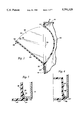
- FIG. 5 is a partial perspective view of a box-like container and associated pouring/dispensing spout in accordance with a second exemplary embodiment of the invention, with the spout shown in an open position;
- FIG. 6 is a partial side section of the box-like container and associated pouring/dispensing spout illustrated in FIG. 5;
- FIG. 7 is a partial top section of the box-like container and associated pouring/dispensing spout as shown in FIGS. 5 and 6, but with the spout shown in a closed position;
- FIG. 8 is a partial top section similar in orientation to that shown in FIG. 7, but illustrating an alternative construction in accordance with the invention
- FIG. 9 is a partial perspective view of a box-like container and associated pouring/dispensing spout in accordance with a third exemplary embodiment of the invention, with the spout shown in an open position;
- FIG. 10 is a partial side section of the box-like container and associated pouring/dispensing spout shown in FIG. 9;
- FIG. 11 is a partial end view of the box illustrated in FIG. 9, with the pouring/measuring spout removed;
- FIG. 12 is a partial top section similar in orientation to FIG. 11, but illustrating an alternative construction in accordance with the invention.
- a box-like container 10 is shown to incorporate a tilt-out measuring/dispensing spout 12 in accordance with this invention.
- the box 10 is of typical cardboard construction and includes a pair of side panels 14 (one shown), a pair of end panels 16 (one shown), a top panel 18 and a bottom panel (not shown).
- the side panel 16 is die cut to provide a rectangular opening 20 in which the measuring/dispensing spout 12 is seated.
- the invention described herein is equally applicable to other container constructions as well.
- the spout may be mounted in any of the box panels.
- the measuring/dispensing spout 12 includes an integrally molded-in, rectangular frame 22 which includes a substantially flat, outer frame 24 which extends about the periphery of the rectangular opening 20 and which lies flush against the end panel 16.
- the frame 22 also includes substantially parallel side angle portions 26, 28 which extend vertically along the sides of the opening 20, parallel with the side panels 14.
- the frame 22 is received in the opening 20 and cemented to the box end panel 16 by any suitable adhesive, applied as shown at 29 in FIG. 3.
- the measuring/dispensing spout 12 includes an open-topped hopper 30 integrally hinged to the frame 22 along a "living hinge" 32 extending along the lower horizontal edge of the outer frame 24.
- the hopper 30 is formed by a flat front face 34, a pair of parallel side faces 36, 38, and a curved rear wall 40 which curves to intersect the front face 34 adjacent the hinge 32.
- the rear wall 40 thus also functions as a bottom wall for the hopper.
- the side faces 36, 38 are provided with radiused upper edges 42, 44, respectively, which permit the measuring/dispensing hopper 30 to move between open and closed positions, pivoting about the living hinge 32.
- the parallel side faces 36, 38 are each provided with a single snap projection 46 (one shown), which snap passed the frame side faces 26, 28 to releaseably retain the spout 12 in a closed position as explained in greater detail below.
- the upper edge 48 of the front face 34 extends upwardly beyond the opening defined by the frame 24, so that the edge 48 serves as a stop, preventing movement of the front face 34 into the box 10 upon closing of the spout 12 to the position shown in 1A.
- the upper edge 48 (also referred to herein as a "gripping bar") is formed with a narrow upwardly opening groove 50, best seen in FIG. 2, which allows the user to insert his or her fingernail into the slot to facilitate opening of the spout 12 to the position shown in FIG. 1.
- the rear wall 40 has a similar extended edge at 52 (FIG. 3) which limits opening movement of the spout by engaging the interior surface of the end panel 16, along the upper horizontal edge of the opening 20.
- the measuring/dispensing spout 12 be constructed of a molded clear (or transparent) plastic material, and that the front face 34 be provided with measurement indicia 54 (which can wrap around the side faces 36, 38 if desired) which enable the user to precisely determine the amount of material within the hopper 30 with the aid of indicia 54, even while the spout 12 is in the closed position.
- indicia 54 include measurement lines indicating 1/8 cup, 1/4 cup and 1/2 cup, a particularly useful measurement scheme for powdered detergents. Depending on the size of the box 10, and the typically dispensed amounts, the volumetric indicators may vary.
- the user In use, with the measuring/dispensing spout 12 in a closed position (FIG. 1A), the user will tilt or partially invert the box (to an extent dependent on the amount of contents remaining in the box) to the left as viewed in FIG. 1A thereby filling or partially filling the open topped hopper 30 with, for example, powdered detergent. If necessary, by manipulating the box in a back and forth movement, the user is able to add or remove material from the hopper, until just the desired amount is retained therein, aided by the indicia 54 on the front face 34. If, for example, too much material has entered the hopper 30, simply by tilting the box back to the right as viewed in FIG.
- the user is able to transfer material out of the hopper 30 and back into the box 10.
- the user may, at all times, ascertain the amount of material within the hopper by reason of the clear face 34 and clear side surfaces 36, 38.
- at least the front face 34 should be made of clear or transparent material.
- the snap projections 46 prevent the spout 12 from moving to an open position by reason of pressure exerted on the back wall 40 by the contents of the box.
- the user simply pulls the measuring/dispensing spout 12 to an open position (FIGS. 1 and 2) using the groove 50 in the upper edge 48 of the front face 34.
- the front face 34' of the measuring/dispensing hopper 30' may be provided with side sealing flanges 56 (one shown in FIG. 4) which are adapted to abut against the peripheral frame 24'.
- FIGS. 5 through 7 a tilt-out, measuring/dispensing spout in accordance with a second exemplary embodiment is illustrated.
- the box 110 includes side panels 114 (one shown), end panels 116 (one shown), a top panel 118 and a bottom panel (not shown).
- the tilt-out measuring/dispensing spout 112 is seated within a rectangular die-cut opening 120 formed in the end panel 116.
- the peripheral frame 22 has been replaced by a lower hinge leaf 124, to which the measuring/dispensing hopper 130 is integrally hinged along the "living hinge" line 132.
- the hinge leaf 124 is cemented to the end panel 116 in essentially the same manner as the peripheral frame 22 in the first described exemplary embodiment.
- the dispensing hopper 130 includes a front face 134, side faces 136, 138 and a rear face or wall 140.
- the side faces 136, 138 are provided with curved upper edges 142, 144 which allow the dispensing hopper 130 to move between the open and closed positions about the living hinge 132, while engaging the upper edge of the die-cut opening 120.
- the dispensing hopper 130 also includes snap projections 146 (one shown))indicia 154 along the front face 134, and a combined gripping bar/stop bar 148 (including groove 150) extending across the upper edge of the front face 134, and a stop edge 152 along the top of the backwall 140.
- the measuring/dispensing spout 112 will pivot between open and closed positions, while frictionally engaging the edges of the end panel 116 which define the die-cut opening 120.
- the manner of operation of the measuring/dispensing spout 112 is otherwise identical to that described in connection with the embodiment illustrated in FIG. 1, and need not be repeated here.
- FIG. 8 an alternative construction for the second exemplary embodiment is disclosed which incorporates the feature described above with respect to the alternative to the first exemplary embodiment as described in connection with FIG. 4.
- the front face 134' is provided with side sealing flanges 156' (one shown) which are adapted to abut the end panel 116 along the side edges of the die-cut opening 120.
- FIGS. 9-11 A third exemplary embodiment of the invention is illustrated in FIGS. 9-11, and again, similar reference numerals are utilized to designate corresponding components, but with the prefix "2" added. The description of elements which are identical to those in the previously described embodiments, however, need not be repeated.
- the die-cut opening 220 in the end panel 216 of the box 210 is formed so as to provide a flap 260 at the lower end of the opening, as defined by slits 262, 264 which extend below the opening 220, thus creating the flap 260 and a hinge line 266 extending across the lower end of the flap 260. This is best seen in FIG. 11.
- the rear wall 240 is provided with a plurality (four in the embodiment shown) of generally triangular ribs 268 which extend downwardly from the rear wall 270 at a location generally adjacent a portion 270 of the front face 234 which extends below the juncture of wall 240 and front face 234.
- These ribs 268 have vertical front edges 272 which are spaced rearwardly of the portion 270 of front face 234 an amount corresponding substantially to the thickness of the flap 266.
- the spout 212 may be secured to the box 210 by sliding the flap (and cementing the flap) between the front face portion 270 and the ribs 268 as shown best in FIG. 10.
- the measuring/dispenser spout 212 can pivot between open and closed positions about the fold line 266. It should be noted here that the two outermost ribs 268 also serve to close gaps which would otherwise permit undesirable egress of material at the sides of the hopper 230, below the juncture of rear wall 240 and front face 234, when the spout 212 is in the open position.
- the manner in which the measuring/dispenser 212 is utilized, is identical to those described hereinabove in connection with FIGS. 1-3 and 5-7.
- front face 234 of the spout 212 may be provided with side sealing flanges 254 which are adapted to abut the end panel 116 along the parallel vertical edges of the opening 220, as shown in FIG. 12.
- the utilization of clear or substantially transparent material for the measuring/dispensing spout, and particularly the front face thereof, allows the user to precisely measure the amount of box contents to be dispensed from the hopper while the spout remains closed, and without relying blindly upon complex mechanical devices which move the rear wall of the hopper to predesignated locations to thereby change the effective volume of the hopper.
- the present invention provides a simpler and more reliable measuring/dispensing device which is less costly to manufacture and which is more durable and reliable than prior art mechanisms of the type described hereinabove.
Abstract
Description
Claims (8)
Priority Applications (1)
| Application Number | Priority Date | Filing Date | Title |
|---|---|---|---|
| US08/791,677 US5791528A (en) | 1993-09-08 | 1997-01-30 | Clear plastic measuring/dispensing spout for a box-like container |
Applications Claiming Priority (4)
| Application Number | Priority Date | Filing Date | Title |
|---|---|---|---|
| US11767793A | 1993-09-08 | 1993-09-08 | |
| US47766495A | 1995-06-07 | 1995-06-07 | |
| US58958796A | 1996-01-22 | 1996-01-22 | |
| US08/791,677 US5791528A (en) | 1993-09-08 | 1997-01-30 | Clear plastic measuring/dispensing spout for a box-like container |
Related Parent Applications (1)
| Application Number | Title | Priority Date | Filing Date |
|---|---|---|---|
| US58958796A Continuation | 1993-09-08 | 1996-01-22 |
Publications (1)
| Publication Number | Publication Date |
|---|---|
| US5791528A true US5791528A (en) | 1998-08-11 |
Family
ID=27382021
Family Applications (1)
| Application Number | Title | Priority Date | Filing Date |
|---|---|---|---|
| US08/791,677 Expired - Lifetime US5791528A (en) | 1993-09-08 | 1997-01-30 | Clear plastic measuring/dispensing spout for a box-like container |
Country Status (1)
| Country | Link |
|---|---|
| US (1) | US5791528A (en) |
Cited By (20)
| Publication number | Priority date | Publication date | Assignee | Title |
|---|---|---|---|---|
| US5988447A (en) * | 1998-04-30 | 1999-11-23 | Yaski; Jud | Adjustable measuring pour spout |
| US6089416A (en) * | 1999-02-01 | 2000-07-18 | Westvaco Corporation | Integrated measuring system package |
| GB2354226A (en) * | 1999-09-08 | 2001-03-21 | Simon Smith | Dispenser chute for a box |
| US20040118733A1 (en) * | 2002-12-24 | 2004-06-24 | Pauli Donna Kay | Container for monitoring consumption of selected chemical compounds of a liquid |
| US20060233927A1 (en) * | 2005-04-18 | 2006-10-19 | Harish Kumar | Method of " value marking(s)" on a container |
| US20060240152A1 (en) * | 2005-04-20 | 2006-10-26 | Michael Krawzsenek | Graphical indicator for determining an amount of a nutrional element consumed, removed, or remaining in a package |
| US20080217334A1 (en) * | 2007-03-09 | 2008-09-11 | Double "H" Plastics, Inc. | Closure with pour spout |
| US20080283557A1 (en) * | 2007-05-17 | 2008-11-20 | Julianne Desautels | Spout for food stuff container |
| US20080302797A1 (en) * | 2007-06-11 | 2008-12-11 | Evan Ira Phillips | Container |
| US20100018998A1 (en) * | 2009-08-12 | 2010-01-28 | Briles Franklin S | Apparatus for dispensing a measured amount of paste |
| US20100126992A1 (en) * | 2008-11-26 | 2010-05-27 | Evan Ira Phillips | Container |
| US20100145297A1 (en) * | 2008-12-08 | 2010-06-10 | Margarita Aguilo-Pinedo | Single dose medication container |
| CN102765528A (en) * | 2012-07-30 | 2012-11-07 | 张国平 | Bottle body assembly |
| US8857644B2 (en) | 2008-11-26 | 2014-10-14 | B.E. Inventive, Llc | Container |
| USD747199S1 (en) | 2014-01-15 | 2016-01-12 | B.E. Inventive, Llc | Closure for can |
| USD747649S1 (en) | 2014-01-15 | 2016-01-19 | B.E. Inventive, Llc | Can end |
| JP2016108014A (en) * | 2014-12-05 | 2016-06-20 | 大日本印刷株式会社 | Shaking spout member, container with shaking spout member, and filler |
| US20160244218A1 (en) * | 2015-02-25 | 2016-08-25 | Sonoco Development, Inc. | Container and overcap with hinged spout for metered dispensing |
| WO2017191536A1 (en) * | 2016-05-05 | 2017-11-09 | Lubuag Ltd | A procedure for manufacturing a laminated package for solid products in powder or grain form, as well as a package obtained by this procedure |
| US10890476B1 (en) * | 2018-09-19 | 2021-01-12 | Adam A. Zuber | Storage container with measuring spout |
Citations (82)
| Publication number | Priority date | Publication date | Assignee | Title |
|---|---|---|---|---|
| US917649A (en) * | 1908-04-15 | 1909-04-06 | Arthur D Otto | Safety cartridge-loader. |
| US924533A (en) * | 1908-01-11 | 1909-06-08 | Harry B Compton | Acetylene-gas generator. |
| US928022A (en) * | 1907-08-06 | 1909-07-13 | John Boland | Feed for acetylene-gas generators. |
| US1268901A (en) * | 1916-01-08 | 1918-06-11 | Charles L Weil | Closure for discharge-apertures in packages. |
| US1273012A (en) * | 1915-06-09 | 1918-07-16 | John G Souther | Dispensing device. |
| US1411000A (en) * | 1921-08-08 | 1922-03-28 | Condon Bros | Measuring and dispensing device |
| US1619315A (en) * | 1926-10-29 | 1927-03-01 | Richard R Ricketts | Dispensing receptacle |
| US1710119A (en) * | 1928-02-03 | 1929-04-23 | Dillon T Stevens | Visible measure |
| US1714368A (en) * | 1926-08-02 | 1929-05-21 | Hobson Arthur William | Container |
| US1752527A (en) * | 1928-02-15 | 1930-04-01 | Albert P Howard | Measuring device |
| US1802284A (en) * | 1929-07-09 | 1931-04-21 | Stoddard William | Measuring and dispensing device |
| US1965233A (en) * | 1933-02-01 | 1934-07-03 | Waldorf Paper Prod Co | Dispensing carton |
| US1967448A (en) * | 1932-12-23 | 1934-07-24 | Charles S Olson | Dispenser |
| US2069281A (en) * | 1936-09-25 | 1937-02-02 | Chicago Carton Co | Carton |
| US2102877A (en) * | 1936-10-26 | 1937-12-21 | Edward J Barnett | Device for dispensing measured quantities of divided solid material |
| US2205129A (en) * | 1937-07-24 | 1940-06-18 | Lloyd L Sissell | Device for dispensing measured quantities of divided solid material |
| US2214437A (en) * | 1939-10-04 | 1940-09-10 | Continental Can Co | Dispensing container |
| US2311255A (en) * | 1941-04-05 | 1943-02-16 | Read Arthur | Self-attaching pouring spout for receptacles |
| US2370820A (en) * | 1943-10-15 | 1945-03-06 | Harold R Stott | Dispensing bottle |
| US2449285A (en) * | 1944-07-17 | 1948-09-14 | Clark Mfg Co J L | Rotary sifter top |
| US2610770A (en) * | 1946-07-01 | 1952-09-16 | Raymond C Penfield | Measuring dispenser |
| US2613856A (en) * | 1950-07-06 | 1952-10-14 | Oscar L Ely | Measuring dispenser for cartons |
| US2781156A (en) * | 1954-10-13 | 1957-02-12 | William H Wallo | Soap dispenser |
| US2784884A (en) * | 1954-07-27 | 1957-03-12 | Jr Henry P Borie | Measuring and dispensing device |
| US2786612A (en) * | 1956-04-26 | 1957-03-26 | Eugene P Hook | Dispensing device |
| US2804103A (en) * | 1955-04-08 | 1957-08-27 | William H Wall | Bottle cap and measuring device |
| US2811281A (en) * | 1955-01-18 | 1957-10-29 | Donovan Marion | Dispensing container for flowable material |
| US2840124A (en) * | 1953-07-13 | 1958-06-24 | Greene Norman | Reuseable dispensing cover |
| US2844266A (en) * | 1955-04-01 | 1958-07-22 | Hofe George Douglas | Receptacle closure |
| US2898004A (en) * | 1958-02-04 | 1959-08-04 | Seal Spout Corp | Combined multiple compartment container and pouring spout |
| US2943769A (en) * | 1957-03-15 | 1960-07-05 | Seal Spout Corp | Combined container and measuring spout |
| US3020659A (en) * | 1957-04-25 | 1962-02-13 | United Sweets Of America Inc | Candy or pill dispensing container |
| US3033420A (en) * | 1959-11-02 | 1962-05-08 | Betty S Thomas | Method and apparatus for dispensing liquids |
| US3057524A (en) * | 1959-04-02 | 1962-10-09 | George F Shanks | Container structure |
| US3140799A (en) * | 1961-10-17 | 1964-07-14 | Mehr Walter | Closure dispenser for containers |
| US3144180A (en) * | 1961-07-13 | 1964-08-11 | Owens Illinois Glass Co | Dispensing closure |
| US3168223A (en) * | 1962-09-27 | 1965-02-02 | Claude V Capers | Canister with built-in measuring dispenser |
| US3187961A (en) * | 1961-12-11 | 1965-06-08 | Moore George Arlington | Unit premeasure dispenser for containers |
| US3209961A (en) * | 1964-05-15 | 1965-10-05 | Willard D Wassell | Metering and dispensing container |
| US3217940A (en) * | 1962-07-25 | 1965-11-16 | Joseph B Fahn | Ice cube dispenser |
| US3237835A (en) * | 1961-09-19 | 1966-03-01 | Leo Stanger | Pouring spout |
| US3353725A (en) * | 1966-09-22 | 1967-11-21 | Francisco J Caceres | Measuring and dispensing unit |
| US3424355A (en) * | 1967-08-29 | 1969-01-28 | Mcconnell Blumen & Associates | Measuring and dispensing closure |
| US3486665A (en) * | 1967-10-02 | 1969-12-30 | American Can Co | Dispensing can with plastic top |
| US3511416A (en) * | 1968-01-31 | 1970-05-12 | Alethea N Michie | Metering spout |
| US3831833A (en) * | 1972-09-25 | 1974-08-27 | Paluga J | Dispensing carton |
| US3860111A (en) * | 1973-06-11 | 1975-01-14 | Larry G Thompson | Pill container and dispenser |
| US3921862A (en) * | 1974-08-22 | 1975-11-25 | Rodger L Holmstrom | Measuring pour spout |
| US3948105A (en) * | 1975-04-01 | 1976-04-06 | Johnson Jr Earl | Proportioning and mixing graduate |
| US4069935A (en) * | 1977-05-06 | 1978-01-24 | Ferdinand Gutmann & Co. | Child resistant closure |
| US4083467A (en) * | 1977-05-02 | 1978-04-11 | Teledyne Industries, Inc. | Infant training tumbler |
| US4111351A (en) * | 1977-04-25 | 1978-09-05 | Bespak Corporation | Paperboard carton |
| US4144989A (en) * | 1977-09-12 | 1979-03-20 | Joy Walter S | Granular material dispenser |
| US4164301A (en) * | 1977-07-25 | 1979-08-14 | Thayer Arnold A | Safety locking dispenser |
| US4261483A (en) * | 1978-07-03 | 1981-04-14 | Champion International Corporation | Container with spout and blank for making same |
| US4292846A (en) * | 1979-11-02 | 1981-10-06 | Barnett Loren A | Liquid proportioning container |
| US4346823A (en) * | 1980-08-04 | 1982-08-31 | Eppenbach Lawrence C | Multiple function closure |
| US4376497A (en) * | 1980-09-15 | 1983-03-15 | Owens-Illinois, Inc. | Child resistant dispensing closure |
| US4399928A (en) * | 1982-04-14 | 1983-08-23 | Janler Corporation | Closure cap |
| US4544063A (en) * | 1984-10-05 | 1985-10-01 | Neward Lance M | Closure for receptacle |
| US4580687A (en) * | 1984-12-31 | 1986-04-08 | Lewis Duane H | Low profile dispensing cap |
| US4606481A (en) * | 1984-02-17 | 1986-08-19 | Dart Industries | Dispensing closure for spouted container |
| US4610371A (en) * | 1984-10-09 | 1986-09-09 | Dougherty Brothers Company | Tamper evident dispensing closure assembly |
| US4613057A (en) * | 1983-12-14 | 1986-09-23 | Sacchetti John A | Closure |
| US4635828A (en) * | 1984-06-27 | 1987-01-13 | Kaufman John George | Liquid container dispensing cap structure |
| US4643881A (en) * | 1984-12-11 | 1987-02-17 | Olin Corporation | Swimming pool chemical dispenser |
| US4691821A (en) * | 1985-07-29 | 1987-09-08 | Jan Folkmar | Receptacle with at least two chambers for accommodating liquids and pulverized substance, especially coffee powder, milk and/or sugar |
| US4693399A (en) * | 1986-10-17 | 1987-09-15 | Weatherchem Corporation | Two-flap closure |
| US4714181A (en) * | 1986-08-21 | 1987-12-22 | Durkee Industrial Foods Corp. | Condiment bottle cap |
| US4760938A (en) * | 1986-05-19 | 1988-08-02 | Harry Wenger | Dispenser box and snap open/snap shut closure therefor |
| US4802597A (en) * | 1987-01-22 | 1989-02-07 | Alfatechnic Ag | Plastic stopper for a container, with a measuring cup that serves as a cap |
| US4898292A (en) * | 1989-01-17 | 1990-02-06 | J. L. Clark, Inc. | Container closure with hinged flap |
| US4930688A (en) * | 1988-02-15 | 1990-06-05 | Fabricacion De Maquinas, S.A. | Cap for bottles and the like |
| US4936494A (en) * | 1988-07-26 | 1990-06-26 | Weatherchem Corporation | Two-flap container closure |
| US4955513A (en) * | 1990-01-16 | 1990-09-11 | Weatherchem Corporation | Dispensing closure with flap retention |
| US4961521A (en) * | 1989-11-21 | 1990-10-09 | Eckman Ronald E | Adjustable metered dispenser |
| US5002208A (en) * | 1990-01-04 | 1991-03-26 | Towery Alfred L | Product container with built-in measuring dispenser |
| US5011048A (en) * | 1988-07-06 | 1991-04-30 | Mark Alexander D | Liquid dispensing measuring cap |
| US5012959A (en) * | 1988-11-17 | 1991-05-07 | International Paper Company | Pour spout and carton construction |
| US5064106A (en) * | 1989-07-26 | 1991-11-12 | The Procter & Gamble Company | Metered dispensing package |
| US5085331A (en) * | 1990-02-26 | 1992-02-04 | Magenta Corporation | Spooning closure |
| US5139181A (en) * | 1991-02-19 | 1992-08-18 | J. L. Clarke, Inc. | Dispensing fitment for a container |
-
1997
- 1997-01-30 US US08/791,677 patent/US5791528A/en not_active Expired - Lifetime
Patent Citations (82)
| Publication number | Priority date | Publication date | Assignee | Title |
|---|---|---|---|---|
| US928022A (en) * | 1907-08-06 | 1909-07-13 | John Boland | Feed for acetylene-gas generators. |
| US924533A (en) * | 1908-01-11 | 1909-06-08 | Harry B Compton | Acetylene-gas generator. |
| US917649A (en) * | 1908-04-15 | 1909-04-06 | Arthur D Otto | Safety cartridge-loader. |
| US1273012A (en) * | 1915-06-09 | 1918-07-16 | John G Souther | Dispensing device. |
| US1268901A (en) * | 1916-01-08 | 1918-06-11 | Charles L Weil | Closure for discharge-apertures in packages. |
| US1411000A (en) * | 1921-08-08 | 1922-03-28 | Condon Bros | Measuring and dispensing device |
| US1714368A (en) * | 1926-08-02 | 1929-05-21 | Hobson Arthur William | Container |
| US1619315A (en) * | 1926-10-29 | 1927-03-01 | Richard R Ricketts | Dispensing receptacle |
| US1710119A (en) * | 1928-02-03 | 1929-04-23 | Dillon T Stevens | Visible measure |
| US1752527A (en) * | 1928-02-15 | 1930-04-01 | Albert P Howard | Measuring device |
| US1802284A (en) * | 1929-07-09 | 1931-04-21 | Stoddard William | Measuring and dispensing device |
| US1967448A (en) * | 1932-12-23 | 1934-07-24 | Charles S Olson | Dispenser |
| US1965233A (en) * | 1933-02-01 | 1934-07-03 | Waldorf Paper Prod Co | Dispensing carton |
| US2069281A (en) * | 1936-09-25 | 1937-02-02 | Chicago Carton Co | Carton |
| US2102877A (en) * | 1936-10-26 | 1937-12-21 | Edward J Barnett | Device for dispensing measured quantities of divided solid material |
| US2205129A (en) * | 1937-07-24 | 1940-06-18 | Lloyd L Sissell | Device for dispensing measured quantities of divided solid material |
| US2214437A (en) * | 1939-10-04 | 1940-09-10 | Continental Can Co | Dispensing container |
| US2311255A (en) * | 1941-04-05 | 1943-02-16 | Read Arthur | Self-attaching pouring spout for receptacles |
| US2370820A (en) * | 1943-10-15 | 1945-03-06 | Harold R Stott | Dispensing bottle |
| US2449285A (en) * | 1944-07-17 | 1948-09-14 | Clark Mfg Co J L | Rotary sifter top |
| US2610770A (en) * | 1946-07-01 | 1952-09-16 | Raymond C Penfield | Measuring dispenser |
| US2613856A (en) * | 1950-07-06 | 1952-10-14 | Oscar L Ely | Measuring dispenser for cartons |
| US2840124A (en) * | 1953-07-13 | 1958-06-24 | Greene Norman | Reuseable dispensing cover |
| US2784884A (en) * | 1954-07-27 | 1957-03-12 | Jr Henry P Borie | Measuring and dispensing device |
| US2781156A (en) * | 1954-10-13 | 1957-02-12 | William H Wallo | Soap dispenser |
| US2811281A (en) * | 1955-01-18 | 1957-10-29 | Donovan Marion | Dispensing container for flowable material |
| US2844266A (en) * | 1955-04-01 | 1958-07-22 | Hofe George Douglas | Receptacle closure |
| US2804103A (en) * | 1955-04-08 | 1957-08-27 | William H Wall | Bottle cap and measuring device |
| US2786612A (en) * | 1956-04-26 | 1957-03-26 | Eugene P Hook | Dispensing device |
| US2943769A (en) * | 1957-03-15 | 1960-07-05 | Seal Spout Corp | Combined container and measuring spout |
| US3020659A (en) * | 1957-04-25 | 1962-02-13 | United Sweets Of America Inc | Candy or pill dispensing container |
| US2898004A (en) * | 1958-02-04 | 1959-08-04 | Seal Spout Corp | Combined multiple compartment container and pouring spout |
| US3057524A (en) * | 1959-04-02 | 1962-10-09 | George F Shanks | Container structure |
| US3033420A (en) * | 1959-11-02 | 1962-05-08 | Betty S Thomas | Method and apparatus for dispensing liquids |
| US3144180A (en) * | 1961-07-13 | 1964-08-11 | Owens Illinois Glass Co | Dispensing closure |
| US3237835A (en) * | 1961-09-19 | 1966-03-01 | Leo Stanger | Pouring spout |
| US3140799A (en) * | 1961-10-17 | 1964-07-14 | Mehr Walter | Closure dispenser for containers |
| US3187961A (en) * | 1961-12-11 | 1965-06-08 | Moore George Arlington | Unit premeasure dispenser for containers |
| US3217940A (en) * | 1962-07-25 | 1965-11-16 | Joseph B Fahn | Ice cube dispenser |
| US3168223A (en) * | 1962-09-27 | 1965-02-02 | Claude V Capers | Canister with built-in measuring dispenser |
| US3209961A (en) * | 1964-05-15 | 1965-10-05 | Willard D Wassell | Metering and dispensing container |
| US3353725A (en) * | 1966-09-22 | 1967-11-21 | Francisco J Caceres | Measuring and dispensing unit |
| US3424355A (en) * | 1967-08-29 | 1969-01-28 | Mcconnell Blumen & Associates | Measuring and dispensing closure |
| US3486665A (en) * | 1967-10-02 | 1969-12-30 | American Can Co | Dispensing can with plastic top |
| US3511416A (en) * | 1968-01-31 | 1970-05-12 | Alethea N Michie | Metering spout |
| US3831833A (en) * | 1972-09-25 | 1974-08-27 | Paluga J | Dispensing carton |
| US3860111A (en) * | 1973-06-11 | 1975-01-14 | Larry G Thompson | Pill container and dispenser |
| US3921862A (en) * | 1974-08-22 | 1975-11-25 | Rodger L Holmstrom | Measuring pour spout |
| US3948105A (en) * | 1975-04-01 | 1976-04-06 | Johnson Jr Earl | Proportioning and mixing graduate |
| US4111351A (en) * | 1977-04-25 | 1978-09-05 | Bespak Corporation | Paperboard carton |
| US4083467A (en) * | 1977-05-02 | 1978-04-11 | Teledyne Industries, Inc. | Infant training tumbler |
| US4069935A (en) * | 1977-05-06 | 1978-01-24 | Ferdinand Gutmann & Co. | Child resistant closure |
| US4164301A (en) * | 1977-07-25 | 1979-08-14 | Thayer Arnold A | Safety locking dispenser |
| US4144989A (en) * | 1977-09-12 | 1979-03-20 | Joy Walter S | Granular material dispenser |
| US4261483A (en) * | 1978-07-03 | 1981-04-14 | Champion International Corporation | Container with spout and blank for making same |
| US4292846A (en) * | 1979-11-02 | 1981-10-06 | Barnett Loren A | Liquid proportioning container |
| US4346823A (en) * | 1980-08-04 | 1982-08-31 | Eppenbach Lawrence C | Multiple function closure |
| US4376497A (en) * | 1980-09-15 | 1983-03-15 | Owens-Illinois, Inc. | Child resistant dispensing closure |
| US4399928A (en) * | 1982-04-14 | 1983-08-23 | Janler Corporation | Closure cap |
| US4613057A (en) * | 1983-12-14 | 1986-09-23 | Sacchetti John A | Closure |
| US4606481A (en) * | 1984-02-17 | 1986-08-19 | Dart Industries | Dispensing closure for spouted container |
| US4635828A (en) * | 1984-06-27 | 1987-01-13 | Kaufman John George | Liquid container dispensing cap structure |
| US4544063A (en) * | 1984-10-05 | 1985-10-01 | Neward Lance M | Closure for receptacle |
| US4610371A (en) * | 1984-10-09 | 1986-09-09 | Dougherty Brothers Company | Tamper evident dispensing closure assembly |
| US4643881A (en) * | 1984-12-11 | 1987-02-17 | Olin Corporation | Swimming pool chemical dispenser |
| US4580687A (en) * | 1984-12-31 | 1986-04-08 | Lewis Duane H | Low profile dispensing cap |
| US4691821A (en) * | 1985-07-29 | 1987-09-08 | Jan Folkmar | Receptacle with at least two chambers for accommodating liquids and pulverized substance, especially coffee powder, milk and/or sugar |
| US4760938A (en) * | 1986-05-19 | 1988-08-02 | Harry Wenger | Dispenser box and snap open/snap shut closure therefor |
| US4714181A (en) * | 1986-08-21 | 1987-12-22 | Durkee Industrial Foods Corp. | Condiment bottle cap |
| US4693399A (en) * | 1986-10-17 | 1987-09-15 | Weatherchem Corporation | Two-flap closure |
| US4802597A (en) * | 1987-01-22 | 1989-02-07 | Alfatechnic Ag | Plastic stopper for a container, with a measuring cup that serves as a cap |
| US4930688A (en) * | 1988-02-15 | 1990-06-05 | Fabricacion De Maquinas, S.A. | Cap for bottles and the like |
| US5011048A (en) * | 1988-07-06 | 1991-04-30 | Mark Alexander D | Liquid dispensing measuring cap |
| US4936494A (en) * | 1988-07-26 | 1990-06-26 | Weatherchem Corporation | Two-flap container closure |
| US5012959A (en) * | 1988-11-17 | 1991-05-07 | International Paper Company | Pour spout and carton construction |
| US4898292A (en) * | 1989-01-17 | 1990-02-06 | J. L. Clark, Inc. | Container closure with hinged flap |
| US5064106A (en) * | 1989-07-26 | 1991-11-12 | The Procter & Gamble Company | Metered dispensing package |
| US4961521A (en) * | 1989-11-21 | 1990-10-09 | Eckman Ronald E | Adjustable metered dispenser |
| US5002208A (en) * | 1990-01-04 | 1991-03-26 | Towery Alfred L | Product container with built-in measuring dispenser |
| US4955513A (en) * | 1990-01-16 | 1990-09-11 | Weatherchem Corporation | Dispensing closure with flap retention |
| US5085331A (en) * | 1990-02-26 | 1992-02-04 | Magenta Corporation | Spooning closure |
| US5139181A (en) * | 1991-02-19 | 1992-08-18 | J. L. Clarke, Inc. | Dispensing fitment for a container |
Cited By (28)
| Publication number | Priority date | Publication date | Assignee | Title |
|---|---|---|---|---|
| US5988447A (en) * | 1998-04-30 | 1999-11-23 | Yaski; Jud | Adjustable measuring pour spout |
| WO2001023297A1 (en) * | 1998-04-30 | 2001-04-05 | Jud Yaski | Adjustable measuring pour spout |
| US6089416A (en) * | 1999-02-01 | 2000-07-18 | Westvaco Corporation | Integrated measuring system package |
| GB2354226A (en) * | 1999-09-08 | 2001-03-21 | Simon Smith | Dispenser chute for a box |
| US20040118733A1 (en) * | 2002-12-24 | 2004-06-24 | Pauli Donna Kay | Container for monitoring consumption of selected chemical compounds of a liquid |
| US6837376B2 (en) | 2002-12-24 | 2005-01-04 | Donna Kay Pauli | Container for monitoring consumption of selected chemical compounds of a liquid |
| US20060233927A1 (en) * | 2005-04-18 | 2006-10-19 | Harish Kumar | Method of " value marking(s)" on a container |
| US20060240152A1 (en) * | 2005-04-20 | 2006-10-26 | Michael Krawzsenek | Graphical indicator for determining an amount of a nutrional element consumed, removed, or remaining in a package |
| US20080217334A1 (en) * | 2007-03-09 | 2008-09-11 | Double "H" Plastics, Inc. | Closure with pour spout |
| US20080283557A1 (en) * | 2007-05-17 | 2008-11-20 | Julianne Desautels | Spout for food stuff container |
| US20080302797A1 (en) * | 2007-06-11 | 2008-12-11 | Evan Ira Phillips | Container |
| US9878833B2 (en) | 2008-11-26 | 2018-01-30 | B.E. Inventive, Llc | Container closure system |
| US20100126992A1 (en) * | 2008-11-26 | 2010-05-27 | Evan Ira Phillips | Container |
| US8857644B2 (en) | 2008-11-26 | 2014-10-14 | B.E. Inventive, Llc | Container |
| US20100145297A1 (en) * | 2008-12-08 | 2010-06-10 | Margarita Aguilo-Pinedo | Single dose medication container |
| US7882989B2 (en) * | 2009-08-12 | 2011-02-08 | Briles Franklin S | Apparatus for dispensing a measured amount of paste |
| US20100018998A1 (en) * | 2009-08-12 | 2010-01-28 | Briles Franklin S | Apparatus for dispensing a measured amount of paste |
| CN102765528A (en) * | 2012-07-30 | 2012-11-07 | 张国平 | Bottle body assembly |
| USD747199S1 (en) | 2014-01-15 | 2016-01-12 | B.E. Inventive, Llc | Closure for can |
| USD747649S1 (en) | 2014-01-15 | 2016-01-19 | B.E. Inventive, Llc | Can end |
| JP2016108014A (en) * | 2014-12-05 | 2016-06-20 | 大日本印刷株式会社 | Shaking spout member, container with shaking spout member, and filler |
| US20160244218A1 (en) * | 2015-02-25 | 2016-08-25 | Sonoco Development, Inc. | Container and overcap with hinged spout for metered dispensing |
| US9759594B2 (en) * | 2015-02-25 | 2017-09-12 | Sonoco Development, Inc. | Container and overcap with hinged spout for metered dispensing |
| US9829362B2 (en) | 2015-02-25 | 2017-11-28 | Sonoco Development, Inc. | Container and spout with open-position locking feature |
| WO2017191536A1 (en) * | 2016-05-05 | 2017-11-09 | Lubuag Ltd | A procedure for manufacturing a laminated package for solid products in powder or grain form, as well as a package obtained by this procedure |
| US10392154B2 (en) * | 2016-05-05 | 2019-08-27 | Lubuag Ltd. | Procedure for manufacturing a laminated package for solid products in powder or grain form, as well as a package obtained by this procedure |
| US10947005B2 (en) | 2016-05-05 | 2021-03-16 | Lubuag Ltd. | Procedure for manufacturing a laminated package for solid products in powder or grain form, as well as a package obtained by this procedure |
| US10890476B1 (en) * | 2018-09-19 | 2021-01-12 | Adam A. Zuber | Storage container with measuring spout |
Similar Documents
| Publication | Publication Date | Title |
|---|---|---|
| US5791528A (en) | Clear plastic measuring/dispensing spout for a box-like container | |
| US5547109A (en) | Container and measuring/dispensing cap assembly | |
| CA2205843C (en) | Dispensing cap with measuring chamber and sifter | |
| JPH06510974A (en) | Measuring equipment for powder products | |
| US5667106A (en) | Container cap with a measuring spout | |
| US5873493A (en) | Integrally molded measurer/dispenser | |
| US4318500A (en) | Cap for dispensing predetermined quantities of flowable material | |
| EP0830573A1 (en) | Measuring canister | |
| US3235143A (en) | Dispensing container | |
| US7213620B2 (en) | Combination cap and adjustable spoon for container | |
| US5182948A (en) | Adjustable measuring container | |
| US3921862A (en) | Measuring pour spout | |
| US20080185403A1 (en) | Dispensing container for flowable product | |
| US4782984A (en) | Pouring device with quantitative chamber for powdery or granular materials | |
| US6125699A (en) | Adjustable measuring spoon | |
| US2799436A (en) | Devices for dispensing measured amounts | |
| US5971216A (en) | Measuring canister with sliding closure | |
| JP4226727B2 (en) | Seasoning storage container | |
| US5002208A (en) | Product container with built-in measuring dispenser | |
| US4871095A (en) | Container for dispensing a measured amount of a granulated solid | |
| US3511416A (en) | Metering spout | |
| US4261483A (en) | Container with spout and blank for making same | |
| US3227330A (en) | Device for sealing, opening, measuring and dispensing flowable substances from a container | |
| JPH11208702A (en) | Tablet container | |
| US4637529A (en) | Measuring dispenser |
Legal Events
| Date | Code | Title | Description |
|---|---|---|---|
| STCF | Information on status: patent grant |
Free format text: PATENTED CASE |
|
| FPAY | Fee payment |
Year of fee payment: 4 |
|
| AS | Assignment |
Owner name: UNION PLANTERS BANK, NATIONAL ASSOCIATION, ALABAMA Free format text: ASSIGNMENT OF ASSIGNORS INTEREST;ASSIGNORS:ROBBINS, E.S., III;ROBBINS, MARY L.;REEL/FRAME:012852/0225 Effective date: 20020417 |
|
| AS | Assignment |
Owner name: UNION PLANTER BANK, NATIONAL ASSOCIATION, ALASKA Free format text: SECURITY AGREEMENT;ASSIGNORS:E.S. ROBBINS CORPORATION;CENTAUR HTP NORTHEAST FENCING SYSTEMS, INC.;ROBBINS, E.S., III;AND OTHERS;REEL/FRAME:014227/0555 Effective date: 20020401 |
|
| FPAY | Fee payment |
Year of fee payment: 8 |
|
| FPAY | Fee payment |
Year of fee payment: 12 |