US5796554A - Load beam assembly with separate spring and hinge functions - Google Patents
Load beam assembly with separate spring and hinge functions Download PDFInfo
- Publication number
- US5796554A US5796554A US08/831,991 US83199197A US5796554A US 5796554 A US5796554 A US 5796554A US 83199197 A US83199197 A US 83199197A US 5796554 A US5796554 A US 5796554A
- Authority
- US
- United States
- Prior art keywords
- load beam
- hinge
- gimbal
- assembly
- base portion
- Prior art date
- Legal status (The legal status is an assumption and is not a legal conclusion. Google has not performed a legal analysis and makes no representation as to the accuracy of the status listed.)
- Expired - Lifetime
Links
Images


Classifications
-
- G—PHYSICS
- G11—INFORMATION STORAGE
- G11B—INFORMATION STORAGE BASED ON RELATIVE MOVEMENT BETWEEN RECORD CARRIER AND TRANSDUCER
- G11B5/00—Recording by magnetisation or demagnetisation of a record carrier; Reproducing by magnetic means; Record carriers therefor
- G11B5/48—Disposition or mounting of heads or head supports relative to record carriers ; arrangements of heads, e.g. for scanning the record carrier to increase the relative speed
- G11B5/4806—Disposition or mounting of heads or head supports relative to record carriers ; arrangements of heads, e.g. for scanning the record carrier to increase the relative speed specially adapted for disk drive assemblies, e.g. assembly prior to operation, hard or flexible disk drives
- G11B5/486—Disposition or mounting of heads or head supports relative to record carriers ; arrangements of heads, e.g. for scanning the record carrier to increase the relative speed specially adapted for disk drive assemblies, e.g. assembly prior to operation, hard or flexible disk drives with provision for mounting or arranging electrical conducting means or circuits on or along the arm assembly
-
- G—PHYSICS
- G11—INFORMATION STORAGE
- G11B—INFORMATION STORAGE BASED ON RELATIVE MOVEMENT BETWEEN RECORD CARRIER AND TRANSDUCER
- G11B21/00—Head arrangements not specific to the method of recording or reproducing
- G11B21/16—Supporting the heads; Supporting the sockets for plug-in heads
-
- G—PHYSICS
- G11—INFORMATION STORAGE
- G11B—INFORMATION STORAGE BASED ON RELATIVE MOVEMENT BETWEEN RECORD CARRIER AND TRANSDUCER
- G11B21/00—Head arrangements not specific to the method of recording or reproducing
- G11B21/16—Supporting the heads; Supporting the sockets for plug-in heads
- G11B21/20—Supporting the heads; Supporting the sockets for plug-in heads while the head is in operative position but stationary or permitting minor movements to follow irregularities in surface of record carrier
- G11B21/21—Supporting the heads; Supporting the sockets for plug-in heads while the head is in operative position but stationary or permitting minor movements to follow irregularities in surface of record carrier with provision for maintaining desired spacing of head from record carrier, e.g. fluid-dynamic spacing, slider
-
- G—PHYSICS
- G11—INFORMATION STORAGE
- G11B—INFORMATION STORAGE BASED ON RELATIVE MOVEMENT BETWEEN RECORD CARRIER AND TRANSDUCER
- G11B5/00—Recording by magnetisation or demagnetisation of a record carrier; Reproducing by magnetic means; Record carriers therefor
- G11B5/48—Disposition or mounting of heads or head supports relative to record carriers ; arrangements of heads, e.g. for scanning the record carrier to increase the relative speed
- G11B5/4806—Disposition or mounting of heads or head supports relative to record carriers ; arrangements of heads, e.g. for scanning the record carrier to increase the relative speed specially adapted for disk drive assemblies, e.g. assembly prior to operation, hard or flexible disk drives
- G11B5/4813—Mounting or aligning of arm assemblies, e.g. actuator arm supported by bearings, multiple arm assemblies, arm stacks or multiple heads on single arm
-
- G—PHYSICS
- G11—INFORMATION STORAGE
- G11B—INFORMATION STORAGE BASED ON RELATIVE MOVEMENT BETWEEN RECORD CARRIER AND TRANSDUCER
- G11B5/00—Recording by magnetisation or demagnetisation of a record carrier; Reproducing by magnetic means; Record carriers therefor
- G11B5/48—Disposition or mounting of heads or head supports relative to record carriers ; arrangements of heads, e.g. for scanning the record carrier to increase the relative speed
- G11B5/4806—Disposition or mounting of heads or head supports relative to record carriers ; arrangements of heads, e.g. for scanning the record carrier to increase the relative speed specially adapted for disk drive assemblies, e.g. assembly prior to operation, hard or flexible disk drives
- G11B5/4833—Structure of the arm assembly, e.g. load beams, flexures, parts of the arm adapted for controlling vertical force on the head
-
- G—PHYSICS
- G11—INFORMATION STORAGE
- G11B—INFORMATION STORAGE BASED ON RELATIVE MOVEMENT BETWEEN RECORD CARRIER AND TRANSDUCER
- G11B21/00—Head arrangements not specific to the method of recording or reproducing
- G11B21/16—Supporting the heads; Supporting the sockets for plug-in heads
- G11B21/26—Means for interchange or replacement of head or head element
-
- G—PHYSICS
- G11—INFORMATION STORAGE
- G11B—INFORMATION STORAGE BASED ON RELATIVE MOVEMENT BETWEEN RECORD CARRIER AND TRANSDUCER
- G11B5/00—Recording by magnetisation or demagnetisation of a record carrier; Reproducing by magnetic means; Record carriers therefor
- G11B5/48—Disposition or mounting of heads or head supports relative to record carriers ; arrangements of heads, e.g. for scanning the record carrier to increase the relative speed
- G11B5/50—Interchangeable mountings, e.g. for replacement of head without readjustment
Definitions
- the invention relates to a magnetic disk drive ("disk drive”) and more particularly to an improved load beam assembly within the disk drive, the improved load beam assembly having structure for performing a spring function and independent structure for performing a hinge function.
- a conventional disk drive has a head disk assembly including at least one magnetic disk (“disk”), a spindle motor for rapidly rotating the disk, and a head stack assembly that includes a transducer head (“head”) for reading and writing data.
- the head stack assembly is controllably positioned by a servo system in order to read or write information on the disk.
- the typical head stack assembly has two primary portions: (1) an actuator assembly that moves in response to the servo control system and (2) a head gimbal assembly (“HGA”) that extends from the actuator assembly and biases the head towards the disk.
- HGA head gimbal assembly
- a "rotary" actuator assembly including an actuator body that rotates on a pivot assembly, a coil that extends from one side of the actuator body to interact with a pair of permanent magnets to form a voice coil motor for moving the actuator body, and an actuator arm that extends from an opposite side of the actuator body to support the head gimbal assembly.
- the conventional HGA includes a suspension assembly, wires, and a head.
- the suspension assembly itself comprises a load beam assembly and a gimbal.
- the load beam assembly has an actuator end that connects to the actuator arm and a gimbal end that connects to the gimbal which carries the head and transmits a biasing force to the head to "load" it against the disk with a biasing force known as a gram load.
- a rapidly spinning disk develops a laminar air flow above its surface that lifts the head away from the disk in opposition to the gram load biasing force.
- the head is said to be "flying" over the disk when in this state.
- the load beam assembly has a spring function which provides the gram load biasing force and a hinge function which permits the head to follow the surface contour of the spinning disk.
- FIG. 3 shows a typical HGA having a load beam assembly that was formed from a thin sheet of stainless steel.
- the industry sometimes refers to a region 83 of this load beam assembly as a "spring hinge” because it functions both as a spring and as a hinge.
- a spring hinge is U.S. Pat. No. 5,283,704, issued to John R. Reidenbach on Feb. 1, 1994, and entitled “ROTARY ACTUATOR FOR DISK DRIVE ASSEMBLIES.”
- the spring hinge 83 is commonly defined by a cut-out 80 which defines web members 81 that make the spring hinge more flexible.
- a spring hinge 83 detrimentally requires a number of engineering compromises to optimize competing interests within a particular load beam assembly.
- the spring hinge 83 should be soft in the bending direction, yet very stiff in both the lateral and torsional motions. The bending softness is necessary so that variations in the Z-height due to drive component tolerances do not dramatically affect gram load imparted to the transducer head. Torsional and lateral stiffness is desired to minimize the affect of resonances which can cause the transducer to oscillate off track.
- the soft bending stiffness at the expense of torsional stiffness.
- special design and controls of hinge geometry are necessary in order to control the off track gain of the first torsional mode. These special controls require a fine tuned process, tight process controls, and therefore add cost.
- the web members 81 are formed to provide the proper pre-load and then stress relieved with some form of heating (IR heat or hot gas).
- FIG. 4 has a plastic base plate 102 and plastic load beam 106 that are connected together by "stabilizer bars" 122 above a metal strip 114.
- Oberg et al. describe their metal strip 114 as a "spring” and further claim that their "stabilizer bars” 122 function as a "hinge.”
- the Oberg et al. device suffers from the same detriments as the device shown in FIG. 3 because the metal strip 114 is fastened to both the base 102 and the load beam 106 forming a "box" structure which in combination is inherently a "spring hinge.”
- a load beam assembly appears deceptively simple, but performs a number of complicated functions. It provides the gram load biasing force needed to properly fly the head. It must provide a minimal and predictable gram load variation over a high volume manufacturing process as the assembly and parts tolerances can cause a Z-height range of about ⁇ 0.008". It must also follow the surface contour of the rotating disk.
- the load beam assembly must provide lateral, longitudinal, and torsional stiffness in supporting the gimbal and head so that the servo system can keep the head over a desired data track. These goals must be achieved at relatively low cost due to the competitive market in which disk drives are sold. The prior art load beam assemblies have largely achieved these goals. Significant advancements in cost and performance could still be obtained, however, by eliminating the compromises required by the conventional "spring hinge" structure.
- the invention may be regarded as a load beam assembly for attachment to an actuator arm and for carrying a head.
- the load beam assembly comprises a base portion having a base actuator end and a base hinge end, and an elongated load beam having a load beam hinge end, a load beam gimbal end, and a bearing surface, the base portion and elongated load beam defining a longitudinal axis extending from the base portion to the load beam gimbal end.
- a hinge means for joining the base hinge end to the load beam hinge end the hinge means defining a transverse axis.
- a gimbal means attached to the load beam gimbal supports the head.
- a spring member having opposite ends with a near end fixed relative to the base portion and a far end contacting the bearing surface, whereby the spring member applies a gram load to the gimbal means via the bearing surface as the load beam pivots about the transverse axis, thereby allowing a narrow range of gram load variation over a wide range of manufactured load beam assemblies.
- the invention may be regarded as a head stack assembly for a magnetic disk drive having a coil, an actuator body, an actuator arm, and a head gimbal assembly for carrying a head over a magnetic disk and applying a gram load to the head, the head gimbal assembly comprising a head for reading recorded magnetic data; connection means for carrying signals from the head; and a load beam assembly as described above.
- the invention may be regarded as a magnetic disk drive having a disk and a head stack assembly, the head stack assembly having a coil, an actuator body, an actuator arm, and a head gimbal assembly for carrying a head over a magnetic disk and applying a gram load to the head, the head gimbal assembly comprising a head for reading recorded magnetic data; connection means for carrying signals from the head; and a load beam assembly as described above.
- FIG. 1 is an exploded perspective view of a magnetic disk drive 15 having a head disk assembly 60 including a head stack assembly 10 having a rotary actuator assembly 20 and a plurality of head gimbal assemblies 100;
- FIG. 2 is a perspective view of the head stack assembly 10 of FIG. 1, showing the outer actuator arms 31 that each support one head gimbal assembly 100, and inner actuator arms 32 that each support two head gimbal assemblies 100;
- FIG. 3 is a perspective view of a conventional head gimbal assembly incorporating a spring hinge 83 defined by a cutout 80 and associated web members 81;
- FIG. 4 is a perspective view of a prior art head gimbal assembly wherein a spring hinge 114 connects a plastic base plate 102 and a plastic load beam 106;
- FIG. 5 is a diagrammatic perspective view of a load beam assembly 110 according to the invention wherein a base portion 120 and an elongated load beam 130 are connected together by a hinge means 150, and wherein a separate spring member 160 is fixed to the base portion 120 and slidably biases against a bearing surface 135 of the load beam 130.;
- FIG. 6 is a perspective view of a portion of head stack assembly 10 having a plurality of load beam assemblies 210 according to a preferred embodiment of the invention
- FIG. 7 is a perspective view of an inner actuator arm 32 which includes means for releasable connection to a pair of load beam assemblies 210;
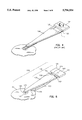
- FIG. 8 is a perspective view of an outer actuator arm 31 connected to a load beam assembly 210;
- FIG. 9 is a sectional view of the outer actuator arm 31 and load beam assembly 210 of FIG. 8 taken along section lines 9--9;
- FIG. 9a is a partial sectional view of a first alternative hinge structure
- FIG. 9b is a partial sectional view of a second alternative hinge structure
- FIG. 10 is a close-up perspective, cut-away view of the far end of the load beam assembly 210 of FIG. 8 with the gimbal ring 180 and head 140 removed to reveal the cross-member 233 which forms a preferred bearing surface that slidably contacts the spring member 260;
- FIGS. 11A, 11B and 11C show a load beam assembly with a third alternative hinge structure involving a ball and socket arrangement
- FIGS. 12, 12A, and 12B show a load beam assembly with second and third alternative spring members 660, 660' that are indirectly affixed to the base portion 620 via a fixed arm extension 661;
- FIG. 13 shows a load beam assembly with a fourth alternative spring member 760.
- FIG. 1 shows the principal components of a disk drive 15 constructed in accordance with a preferred embodiment of the invention.
- the disk drive 15 shown is an integrated drive electronics (IDE) drive, comprising a head disk assembly (HDA) 60 and a controller circuit board 70.
- IDE integrated drive electronics
- the HDA 60 of FIG. 1 comprises a magnetic disk 64 (2 shown), a spindle motor 62 for rapidly rotating the disk 64, and a head stack assembly 10 located next to the disk 64.
- the head stack assembly 10 comprises an actuator assembly 20 and a plurality of head gimbal assemblies 100.
- Each head gimbal assembly 100 comprises a load beam assembly 110 and a head 140 supported by gimbal means 180, as conceptually shown in FIG. 5.
- the actuator assembly 20 comprises a voice coil 50, an actuator body 40, and actuator arms 31, 32 (see FIG. 2).
- the head stack assembly 10 is located so that the head 140 of the head gimbal assembly 100 is biased towards and moveable over the disk 64.
- the HDA's storage capacity may be increased, as shown in FIG. 1, by including several disks 64 and a head stack assembly 10 having a vertical "stack" of head gimbal assemblies 100 and associated heads 140 for each surface of each disk 64, the head gimbal assemblies 100 supported by multiple actuator arms 31, 32.
- actuator assembly 20 is preferably an integrally molded structure wherein the voice coil 50 and actuator arms 31, 32 are simultaneously molded with the actuator body 40.
- the voice coil 50 and actuator arms 31, 32 may be pre-formed and then insert molded into the actuator body 40.
- the actuator arms 31, 32 may also be injection molded components and, as further shown in FIG. 2, may include internal conductors 36 with a first plurality of conductive pads or pins 33 exposed on the side of the actuator body 40 and a second plurality of conductive pads 34 exposed at a far end and on one side of an outer actuator arm 31 and on both sides of an inner actuator arm 32.
- the conductors 36, conductive pins 33, and conductive pads 34 are used to communicate read and write signals and to provide a ground path between the heads 140 and the controller circuit board 70.
- the preferred head gimbal assembly 100 comprises a load beam assembly 110, a head 140, a gimbal means 180 for supporting the head 140, and a conductive means for carrying signals to and from the head 140.
- FIG. 5 generally shows the conceptual construction of a load beam assembly 110 according to the invention in the context of an overall head gimbal assembly 100.
- the load beam assembly 110 comprises a base portion 120, a load beam 130 having a gimbal end 131 and a bearing surface 135, a hinge means 150 for pivotally connecting a load beam hinge end 132 of the load beam 130 to a base hinge end 124 of the base portion 120, and an elongated spring member 160 that arches along a longitudinal axis of the assembly, the spring member 160 having a near end 161 that is fixed to the base portion 120 and a far end 162 that slidably contacts the bearing surface 135 of the load beam 130 as it pivots about the transverse axis.
- a gimbal means 180 for supporting a head 140 over a disk 64 is attached to the gimbal end 131 of the load beam 130.
- the base portion 120 preferably has a base actuator end 125 that releasably connects to an actuator arm 31, 32, as further discussed below.
- the spring member must be fixed relative to the base portion 120 and the preferred spring member has its near end 161 fixed directly to the base portion 120. It is possible, of course, to use a different type of spring member that is fixed to a cantilevered member, for example, which cantilevered member is, in turn, fixed to the base portion 120.
- the hinge means 150 of FIG. 5 functions as a "true hinge” because it does not flex, but rather provides rotation about a hinge pin 152 and offers little or no spring-like resistance to movement. Conversely stated, the unique structure of FIG. 5 has moved most or all of the spring function into the spring member 160. A hinge comparable to that of FIG. 5 could, of course, be formed from any rotating, non-flexing interface.
- the industry generally establishes the spring function of a conventional load beam assembly, one of the "hinge spring” variety, by starting with a sheet of a particular thickness (say 3 mils) and then determining the length of the cutout 80 that provides the spring constant needed for the desired gram load.
- a thicker sheet could be used with a longer cutout 80, or vice versa, to achieve the same spring constant.
- a shorter cutout improves lateral and torsional stiffness, but increases the bending stiffness. If the material thickness is decreases, the stress increases for a given gram load.
- a longer cutout reduces the bending stiffness, but makes the load beam assembly torsionally soft.
- a spring member 160 according to the invention is isolated from the hinge function and does not have to provide the stiffness. Accordingly, the spring member 160 may have reduced spring rate that translates to a reduced gram load variation.
- a flexure hinge it can be made thin and short since the stress can be near zero at nominal Z-height.
- FIG. 8 shows a preferred load beam assembly 210 according to the invention.
- a base 220, a load beam 230, and a hinge member 250 are all integrally formed from a common injection molded component.
- the hinge member 250 is defined as a "living hinge” through the use of a reduced thickness in material.
- the hinge member 250 is not a "true” hinge 150 like that shown in FIG. 5, but for all practical purposes, the spring-like characteristics of the hinge member 250 are negligible compared to those of the spring member 260.
- the spring member 260 preferably comprises a spring strip 260 formed from cold rolled austenitic, stainless steel.
- the preferred spring strip 260 is about 0.0025" thick, 0.030" wide, and 0.425" long.
- the material composition and dimensions of the spring strip 260 may be easily varied to achieve a predetermined spring rate suitable for a given application and, beneficially, without any concern for hinge related functionality.
- FIG. 6 shows a portion of a preferred head stack assembly 10 including a "stack" of preferred load beam assemblies 210 attached to outer actuator arms 31 and inner actuator arms 32.
- the spring strip 260 extends from between a notched anchor block 225 and a support block 226 toward a cross-member 233 located at a gimbal end 232 of the load beam 230.
- the cross-member 233 defines a bearing surface along which the spring strip 260 may slide as the load beam 230 pivots about the hinge member 250.
- the spring strip 260 biases the gimbal end 232 of the load beam 230 upward about a transverse rotational axis of the hinge member 250.
- a head 140 supported by a gimbal means 180 on the load beam 230 is biased towards the disk 64 (not shown) with a predetermined gram load biasing force.
- FIGS. 9A and 9B show alternative hinge members which may be used with a load beam assembly 210 according to the invention.
- a strip of metal 350 such as stainless steel or beryllium copper is bonded or otherwise connected between the base 220 and the load beam 230.
- the base 220 and load beam 230 may be plastic as was shown in FIG. 9.
- Several metal strips 350 may also be used to carry read and write signals in addition to serving as a hinge member.
- a flex circuit 450 is connected between the base 220 and the load beam 230. The flex circuit 450 uniquely carries conductors for communicating the read and write signals and also physically serves as a hinge member.
- FIG. 10 is a close up perspective, cut-away view of the load beam 230 of FIG. 8 with the gimbal ring 180 and the head 140 removed to reveal the sliding contact between the spring member 260 and the bearing surface 135 of the load beam's cross-member 233.
- FIG. 10 also shows a preferred spherical load point 234 which pivotally supports a back side of the gimbal ring 180 and head 140.
- FIGS. 7 and 8 show a preferred releasable connection means.
- Two bases 220 can be similarly connected to an inner actuator arm 32 with one having its head facing an upper disk and the other having its head facing a lower disk by providing the inner actuator arm 32 with two pairs of opposed notches 35 in a vertically stacked arrangement as shown in FIG. 7.
- the preferred actuators 31, 32 carry internal conductors 36 that interconnect conductive pads 33 on the actuator body (see FIG. 2) with conductive pads 34 exposed at a far end of the actuator arms 31, 32.
- the conductive pads 34 are electrically connected to the heads 140 via corresponding conductive pads 174 on a flex actuator end of a flex circuit 182 as shown in FIG. 8.
- a flex gimbal end of the flex circuit 182 preferably terminates with conductive pads 175 arranged in a circle to interface with a unique gimbal ring 180 that also comprises flex material.
- the gimbal ring 180 may be beneficially replaced or "reworked" to repair an otherwise functional head gimbal assembly 100 to minimize waste during manufacturing and assembly.
- FIG. 11A, 11B and 11C show a third alternative hinge 550 involving a ball and socket arrangement.
- the hinge 550 provides hinging action between a pair of ball detents 535 on the load beam 530 and a corresponding pair of sockets 525 in the base 520.
- An alternative spring member 560 extends from the base 520 to bias the load beam 530 about the hinge assembly 550.
- An alternative to the bails 535 and sockets 525 which can reduce friction is to replace the balls 535 with knife edges (not shown).
- An added benefit of the structures shown in FIGS. 11A-11C is that a top portion 523 of the base 520 limits the movement of the load beam 530.
- a special "shipping comb" must ordinarily be inserted into a head stack assembly to separate the heads 140 before mating the assembly with a stack of disks.
- a variety of alternative spring members may be used in the invention instead of the presently preferred spring member 260.
- FIGS. 12, 12A, and 12B show a load beam assembly with a base portion 620, a load beam 630 which carries a gimbal 680 and a transducer head 640, a hinge member 650 that pivotally connects the load beam 630 to the base portion 620, and second and third alternative spring members 660, 660' that are indirectly affixed to the base portion 620 via a fixed arm extension 661.
- the second alternative spring member 660 comprises a coil spring.
- the spring member 660' comprises at least one nonlinear disk spring.
- FIG. 13 shows a load beam assembly with a base portion 720, a load beam 730 which carries a gimbal 780 and a transducer head 740, a hinge member 750 that pivotally connects the load beam 730 to the base portion 720, and a fourth alternative spring member 760 comprising a wire loop.
- the wire loop 760 makes sliding contact with a bearing surface 735 on the topside of the load beam 730.
- the above disclosure has been provided to teach an innovative load beam assembly 110 that by itself or in combination with a head stack assembly 10 or overall disk drive 15, separates the hinge and spring functions needed to bias a head 140 towards a disk 64.
- the resulting device provides a more consistent spring constant and may be manufactured at less cost and with less waste and higher yield.
Abstract
Description
Claims (66)
Priority Applications (1)
| Application Number | Priority Date | Filing Date | Title |
|---|---|---|---|
| US08/831,991 US5796554A (en) | 1997-04-01 | 1997-04-01 | Load beam assembly with separate spring and hinge functions |
Applications Claiming Priority (1)
| Application Number | Priority Date | Filing Date | Title |
|---|---|---|---|
| US08/831,991 US5796554A (en) | 1997-04-01 | 1997-04-01 | Load beam assembly with separate spring and hinge functions |
Publications (1)
| Publication Number | Publication Date |
|---|---|
| US5796554A true US5796554A (en) | 1998-08-18 |
Family
ID=25260380
Family Applications (1)
| Application Number | Title | Priority Date | Filing Date |
|---|---|---|---|
| US08/831,991 Expired - Lifetime US5796554A (en) | 1997-04-01 | 1997-04-01 | Load beam assembly with separate spring and hinge functions |
Country Status (1)
| Country | Link |
|---|---|
| US (1) | US5796554A (en) |
Cited By (23)
| Publication number | Priority date | Publication date | Assignee | Title |
|---|---|---|---|---|
| US6021023A (en) * | 1998-06-17 | 2000-02-01 | International Business Machines Corporation | Transducer suspension system and method |
| US6057986A (en) * | 1997-07-23 | 2000-05-02 | Suncall Corporation | Support mechanism for magnetic head sliders and method for producing the same |
| US6151198A (en) * | 1998-11-18 | 2000-11-21 | International Business Machines Corporation | Overmolding of actuator E-block by thixotropic or semisolid forging |
| US6498704B1 (en) | 2000-02-23 | 2002-12-24 | Maxtor Corporation | Disk drive with viscoelastic damper disposed between adjacent load beams |
| US6532135B1 (en) * | 2000-06-06 | 2003-03-11 | Maxtor Corporation | Suspension load beam for disk drive actuator |
| US20030086206A1 (en) * | 2001-11-05 | 2003-05-08 | Kube Todd Warren | Load beam attachment to actuator arm |
| WO2003041061A1 (en) * | 2001-11-05 | 2003-05-15 | Seagate Technology Llc | Load beam attachment to actuator arm |
| WO2003105128A2 (en) * | 2002-06-11 | 2003-12-18 | Matsushita Electric Industrial Co., Ltd. | Head support mechanism, head drive device, and disk apparatus |
| US6700747B2 (en) * | 1998-01-06 | 2004-03-02 | Hutchinson Technology Incorporated | Integrated lead head suspension assembly having an etched laminated load beam and flexure with deposited conductors |
| US6778362B1 (en) | 2001-08-31 | 2004-08-17 | Hutchinson Technology, Inc. | Hinged load beam with torsional spring |
| US20040175255A1 (en) * | 1998-09-29 | 2004-09-09 | Trovinger Steven W. | Method and apparatus for making booklets |
| US6870708B1 (en) | 2002-08-28 | 2005-03-22 | Hutchinson Technology Incorporated | Weld pads for head suspensions |
| US7113371B1 (en) * | 2002-02-22 | 2006-09-26 | Western Digital Technologies, Inc. | Suspension design for attenuation of disk flutter induced track mis-registration of a hard disk drive by manipulation of the hinge and/or load beam |
| US20060221503A1 (en) * | 2005-03-31 | 2006-10-05 | Nhk Spring Co., Ltd. | Head suspension |
| US20060221504A1 (en) * | 2005-03-30 | 2006-10-05 | Nhk Spring Co., Ltd. | Head suspension |
| CN1305069C (en) * | 2002-06-28 | 2007-03-14 | Tdk株式会社 | Information head support arm assembly and disk driving device utilziing the same information head support arm assembly |
| US20090060636A1 (en) * | 2005-02-22 | 2009-03-05 | Lev Alexander Prociw | Positioning arrangement for components of a pressure vessel and method |
| US7773344B1 (en) * | 2005-05-16 | 2010-08-10 | Magnecomp Corporation | Suspension having separately optimized torsion stiffness and vertical stiffness |
| US7961434B1 (en) | 2007-09-20 | 2011-06-14 | Hutchinson Technology Incorporated | Disk drive head suspension with leaf spring gram loading |
| US8142671B1 (en) | 2008-08-12 | 2012-03-27 | Western Digital Technologies, Inc. | Method to fabricate a damped suspension assembly |
| US8159785B1 (en) | 2008-08-27 | 2012-04-17 | Western Digital Technologies, Inc. | Disk drive suspension having a constraint layer and a base region with a bridge section extending across a gap between lateral sections |
| US8259416B1 (en) | 2008-05-09 | 2012-09-04 | Hutchinson Technology Incorporated | Head suspension having viscoelastic load point |
| US8416531B2 (en) | 2010-03-23 | 2013-04-09 | Benda Corporation | Head suspension load beam with stiffening features |
Citations (12)
| Publication number | Priority date | Publication date | Assignee | Title |
|---|---|---|---|---|
| US4268879A (en) * | 1979-05-07 | 1981-05-19 | International Business Machines Corporation | Suspension for air bearing head arm assembly |
| US4748522A (en) * | 1985-10-19 | 1988-05-31 | Alps Electric Co., Ltd. | Magnetic head assembly having vibration controlling member |
| US4759119A (en) * | 1985-09-10 | 1988-07-26 | Alps Electric Co., Ltd. | Method of fabricating a magnetic head assembly |
| US4811140A (en) * | 1984-08-31 | 1989-03-07 | Teac Corporation | Magnetic data transfer apparatus having improved transducer coil arrangement |
| US4875117A (en) * | 1986-12-19 | 1989-10-17 | Micropolis Corporation | Digital head positioner assembly |
| US5012369A (en) * | 1988-05-18 | 1991-04-30 | Fujitsu Limited | Head suspension mechanism of a recording apparatus with a constant flying height |
| US5185683A (en) * | 1987-12-21 | 1993-02-09 | Hutchinson Technology, Inc. | Suspension arm mounting assembly |
| US5283704A (en) * | 1990-12-31 | 1994-02-01 | International Business Machines Corporation | Rotary actuator for disk drive assemblies |
| US5446611A (en) * | 1990-09-14 | 1995-08-29 | Hutchinson Technology, Inc. | Head suspension assembly which includes a load beam element having relief channels |
| US5461525A (en) * | 1990-09-14 | 1995-10-24 | Hutchinson Technology Incorporated | Load beam having areas of varying thickness in the spring region formed by varying numbers of lamina |
| US5473488A (en) * | 1994-08-03 | 1995-12-05 | Hutchinson Technology Incorporated | Static attitude adjustment via a solidified drop for a magnetic head suspension |
| US5551145A (en) * | 1993-10-29 | 1996-09-03 | Hutchinson Technology Incorporated | Rigid disk drive assembly method |
-
1997
- 1997-04-01 US US08/831,991 patent/US5796554A/en not_active Expired - Lifetime
Patent Citations (12)
| Publication number | Priority date | Publication date | Assignee | Title |
|---|---|---|---|---|
| US4268879A (en) * | 1979-05-07 | 1981-05-19 | International Business Machines Corporation | Suspension for air bearing head arm assembly |
| US4811140A (en) * | 1984-08-31 | 1989-03-07 | Teac Corporation | Magnetic data transfer apparatus having improved transducer coil arrangement |
| US4759119A (en) * | 1985-09-10 | 1988-07-26 | Alps Electric Co., Ltd. | Method of fabricating a magnetic head assembly |
| US4748522A (en) * | 1985-10-19 | 1988-05-31 | Alps Electric Co., Ltd. | Magnetic head assembly having vibration controlling member |
| US4875117A (en) * | 1986-12-19 | 1989-10-17 | Micropolis Corporation | Digital head positioner assembly |
| US5185683A (en) * | 1987-12-21 | 1993-02-09 | Hutchinson Technology, Inc. | Suspension arm mounting assembly |
| US5012369A (en) * | 1988-05-18 | 1991-04-30 | Fujitsu Limited | Head suspension mechanism of a recording apparatus with a constant flying height |
| US5446611A (en) * | 1990-09-14 | 1995-08-29 | Hutchinson Technology, Inc. | Head suspension assembly which includes a load beam element having relief channels |
| US5461525A (en) * | 1990-09-14 | 1995-10-24 | Hutchinson Technology Incorporated | Load beam having areas of varying thickness in the spring region formed by varying numbers of lamina |
| US5283704A (en) * | 1990-12-31 | 1994-02-01 | International Business Machines Corporation | Rotary actuator for disk drive assemblies |
| US5551145A (en) * | 1993-10-29 | 1996-09-03 | Hutchinson Technology Incorporated | Rigid disk drive assembly method |
| US5473488A (en) * | 1994-08-03 | 1995-12-05 | Hutchinson Technology Incorporated | Static attitude adjustment via a solidified drop for a magnetic head suspension |
Cited By (37)
| Publication number | Priority date | Publication date | Assignee | Title |
|---|---|---|---|---|
| US6057986A (en) * | 1997-07-23 | 2000-05-02 | Suncall Corporation | Support mechanism for magnetic head sliders and method for producing the same |
| US6360427B1 (en) | 1997-07-23 | 2002-03-26 | Suncall Corporation | Method of producing a support mechanism for magnetic head sliders |
| US6700747B2 (en) * | 1998-01-06 | 2004-03-02 | Hutchinson Technology Incorporated | Integrated lead head suspension assembly having an etched laminated load beam and flexure with deposited conductors |
| US6021023A (en) * | 1998-06-17 | 2000-02-01 | International Business Machines Corporation | Transducer suspension system and method |
| US20050105988A9 (en) * | 1998-09-29 | 2005-05-19 | Trovinger Steven W. | Method and apparatus for making booklets |
| US20040175255A1 (en) * | 1998-09-29 | 2004-09-09 | Trovinger Steven W. | Method and apparatus for making booklets |
| US6151198A (en) * | 1998-11-18 | 2000-11-21 | International Business Machines Corporation | Overmolding of actuator E-block by thixotropic or semisolid forging |
| US6498704B1 (en) | 2000-02-23 | 2002-12-24 | Maxtor Corporation | Disk drive with viscoelastic damper disposed between adjacent load beams |
| US6938326B1 (en) | 2000-06-06 | 2005-09-06 | Maxtor Corporation | Method of making at least one suspension load beam for an actuator assembly of a disk drive |
| US6687091B1 (en) | 2000-06-06 | 2004-02-03 | Maxtor Corporation | Suspension load beam for disk drive actuator with notch for reducing spring rate |
| US6532135B1 (en) * | 2000-06-06 | 2003-03-11 | Maxtor Corporation | Suspension load beam for disk drive actuator |
| US6778362B1 (en) | 2001-08-31 | 2004-08-17 | Hutchinson Technology, Inc. | Hinged load beam with torsional spring |
| CN1310213C (en) * | 2001-11-05 | 2007-04-11 | 希捷科技有限公司 | Load beam attachment to actuator arm |
| WO2003041061A1 (en) * | 2001-11-05 | 2003-05-15 | Seagate Technology Llc | Load beam attachment to actuator arm |
| US6865058B2 (en) | 2001-11-05 | 2005-03-08 | Seagate Technology Llc | Load beam attachment to actuator arm |
| GB2397166A (en) * | 2001-11-05 | 2004-07-14 | Seagate Technology Llc | Load beam attachment to actuator arm |
| US20030086206A1 (en) * | 2001-11-05 | 2003-05-08 | Kube Todd Warren | Load beam attachment to actuator arm |
| US7113371B1 (en) * | 2002-02-22 | 2006-09-26 | Western Digital Technologies, Inc. | Suspension design for attenuation of disk flutter induced track mis-registration of a hard disk drive by manipulation of the hinge and/or load beam |
| WO2003105128A3 (en) * | 2002-06-11 | 2004-10-14 | Matsushita Electric Ind Co Ltd | Head support mechanism, head drive device, and disk apparatus |
| WO2003105128A2 (en) * | 2002-06-11 | 2003-12-18 | Matsushita Electric Industrial Co., Ltd. | Head support mechanism, head drive device, and disk apparatus |
| US20060056111A1 (en) * | 2002-06-11 | 2006-03-16 | Yoshihiro Ueno | Head support mechanism head drive device and disk apparatus |
| US7265945B2 (en) | 2002-06-11 | 2007-09-04 | Matsushita Electric Industrial Co., Ltd. | Head drive device including head support mechanism having support arm rotatable relative to base arm via rotation support part, and disk apparatus including the head drive device |
| CN1317693C (en) * | 2002-06-11 | 2007-05-23 | 松下电器产业株式会社 | Head support mechanism, head drive device, and disk apparatus |
| CN1305069C (en) * | 2002-06-28 | 2007-03-14 | Tdk株式会社 | Information head support arm assembly and disk driving device utilziing the same information head support arm assembly |
| US6870708B1 (en) | 2002-08-28 | 2005-03-22 | Hutchinson Technology Incorporated | Weld pads for head suspensions |
| US20090060636A1 (en) * | 2005-02-22 | 2009-03-05 | Lev Alexander Prociw | Positioning arrangement for components of a pressure vessel and method |
| US20060221504A1 (en) * | 2005-03-30 | 2006-10-05 | Nhk Spring Co., Ltd. | Head suspension |
| US7751152B2 (en) * | 2005-03-30 | 2010-07-06 | Nhk Spring Co., Ltd. | Head suspension |
| US20060221503A1 (en) * | 2005-03-31 | 2006-10-05 | Nhk Spring Co., Ltd. | Head suspension |
| US7688549B2 (en) * | 2005-03-31 | 2010-03-30 | Nhk Spring Co., Ltd. | Head suspension |
| US7773344B1 (en) * | 2005-05-16 | 2010-08-10 | Magnecomp Corporation | Suspension having separately optimized torsion stiffness and vertical stiffness |
| US7961434B1 (en) | 2007-09-20 | 2011-06-14 | Hutchinson Technology Incorporated | Disk drive head suspension with leaf spring gram loading |
| US8259416B1 (en) | 2008-05-09 | 2012-09-04 | Hutchinson Technology Incorporated | Head suspension having viscoelastic load point |
| US8142671B1 (en) | 2008-08-12 | 2012-03-27 | Western Digital Technologies, Inc. | Method to fabricate a damped suspension assembly |
| US8159785B1 (en) | 2008-08-27 | 2012-04-17 | Western Digital Technologies, Inc. | Disk drive suspension having a constraint layer and a base region with a bridge section extending across a gap between lateral sections |
| US8869382B1 (en) | 2008-08-27 | 2014-10-28 | Westren Digital Technologies, Inc. | Method of manufacturing a disk drive suspension |
| US8416531B2 (en) | 2010-03-23 | 2013-04-09 | Benda Corporation | Head suspension load beam with stiffening features |
Similar Documents
| Publication | Publication Date | Title |
|---|---|---|
| US5796554A (en) | Load beam assembly with separate spring and hinge functions | |
| US5790347A (en) | Head suspension load beam and flexure construction for reducing structural height | |
| US6965501B1 (en) | Integrated lead suspension for high density drive | |
| US6801398B1 (en) | Magnetic head suspension assembly with adhesion limiting structure | |
| US9042056B2 (en) | Disk drive suspension with microactuator elements on respective slider sides and damper member on gimbal portion away from dimple | |
| US7898770B1 (en) | Disk drive suspension assembly with a hinge arm attached at a recessed surface | |
| US5892637A (en) | Multi-piece integrated suspension assembly for a magnetic storage system | |
| US8964334B2 (en) | Disk drive suspension | |
| US7764467B2 (en) | Suspension for disc drive | |
| US6731472B2 (en) | Suspension for disc drive | |
| US7733607B2 (en) | Suspension with strengthening plate, head gimbal assembly, and disk drive unit with the same | |
| US20090268347A1 (en) | Suspension and disk drive | |
| US7688553B1 (en) | Thermally-compensating attachment of disk drive slider to flexure | |
| JPH0798949A (en) | Suspension system | |
| JP2004522239A (en) | Disk drive with improved head pitch adjustment | |
| US6483670B1 (en) | Head assembly having an apertured reinforcing plate cooperatively attached to a load beam to prevent excessive movement of components of the head assembly | |
| US7359158B2 (en) | Suspension of disc drive | |
| US6954339B2 (en) | Suspension assembly including a shape memory flexure element to adjust flexure or preload force | |
| US20070115591A1 (en) | Suspension, head gimbal assembly and disk drive unit with the same | |
| US20050286176A1 (en) | Head gimbal assembly with flying height adjuster, disk drive unit and manufacturing method thereof | |
| US7009814B2 (en) | Disc drive suspension in which track-direction swing in the low-frequency band is restrained | |
| US7230800B2 (en) | Microactuator for a hard disk drive with an integrated gimbal function | |
| US7551403B2 (en) | HSA with air turbulence preventing structure for HGA, disk drive unit with the same, and manufacturing method thereof | |
| US6549372B1 (en) | Device for limiting head movement within a hard disk drive | |
| JP3405452B2 (en) | Head support mechanism for disk drive |
Legal Events
| Date | Code | Title | Description |
|---|---|---|---|
| AS | Assignment |
Owner name: WESTERN DIGITAL CORPORATION, CALIFORNIA Free format text: ASSIGNMENT OF ASSIGNORS INTEREST;ASSIGNORS:BERDING, KEITH R.;CASEY, SHAWN;REEL/FRAME:008496/0276 Effective date: 19970320 |
|
| STCF | Information on status: patent grant |
Free format text: PATENTED CASE |
|
| AS | Assignment |
Owner name: BANKBOSTON, N.A., AS AGENT, MASSACHUSETTS Free format text: PATENT COLLATERAL ASSIGNMENT AND SECURITY AGREEMENT DATED AS OF NOVEMBER 4, 1998;ASSIGNOR:WESTERN DIGITAL CORPORATION, A DELAWARE CORPORATION;REEL/FRAME:009596/0487 Effective date: 19981104 |
|
| AS | Assignment |
Owner name: WESTERN DIGITAL CORPORATION, CALIFORNIA Free format text: RELEASE BY SECURED PARTY;ASSIGNOR:FLEET NATIONAL BANK (F/K/A BANKBOSTON, N.A.);REEL/FRAME:011089/0459 Effective date: 20000330 |
|
| AS | Assignment |
Owner name: GENERAL ELECTRIC CAPITAL CORPORATION, CALIFORNIA Free format text: SECURITY AGREEMENT;ASSIGNOR:WESTERN DIGITAL CORPORATION;REEL/FRAME:011170/0948 Effective date: 20000920 |
|
| AS | Assignment |
Owner name: WESTERN DIGITAL TECHNOLOGIES, INC., CALIFORNIA Free format text: AMENDED AND RESTATED CERTIFICATE OF INCORPORATION OF WESTERN DIGITAL CORP.;ASSIGNOR:WESTERN DIGITAL CORPORATION;REEL/FRAME:011967/0481 Effective date: 20010406 |
|
| FPAY | Fee payment |
Year of fee payment: 4 |
|
| FPAY | Fee payment |
Year of fee payment: 8 |
|
| AS | Assignment |
Owner name: WESTERN DIGITAL TECHNOLOGIES, INC., CALIFORNIA Free format text: RELEASE BY SECURED PARTY;ASSIGNOR:GENERAL ELECTRIC CAPITAL CORPORATION, AS AGENT;REEL/FRAME:021502/0451 Effective date: 20070809 |
|
| FPAY | Fee payment |
Year of fee payment: 12 |
|
| SULP | Surcharge for late payment |
Year of fee payment: 11 |