US5805975A - Satellite broadcast receiving and distribution system - Google Patents
Satellite broadcast receiving and distribution system Download PDFInfo
- Publication number
- US5805975A US5805975A US08/838,677 US83867797A US5805975A US 5805975 A US5805975 A US 5805975A US 83867797 A US83867797 A US 83867797A US 5805975 A US5805975 A US 5805975A
- Authority
- US
- United States
- Prior art keywords
- signals
- satellite
- head
- frequency
- coupled
- Prior art date
- Legal status (The legal status is an assumption and is not a legal conclusion. Google has not performed a legal analysis and makes no representation as to the accuracy of the status listed.)
- Expired - Lifetime
Links
Images
Classifications
-
- H—ELECTRICITY
- H04—ELECTRIC COMMUNICATION TECHNIQUE
- H04H—BROADCAST COMMUNICATION
- H04H40/00—Arrangements specially adapted for receiving broadcast information
- H04H40/18—Arrangements characterised by circuits or components specially adapted for receiving
- H04H40/27—Arrangements characterised by circuits or components specially adapted for receiving specially adapted for broadcast systems covered by groups H04H20/53 - H04H20/95
- H04H40/90—Arrangements characterised by circuits or components specially adapted for receiving specially adapted for broadcast systems covered by groups H04H20/53 - H04H20/95 specially adapted for satellite broadcast receiving
-
- H—ELECTRICITY
- H04—ELECTRIC COMMUNICATION TECHNIQUE
- H04N—PICTORIAL COMMUNICATION, e.g. TELEVISION
- H04N7/00—Television systems
- H04N7/10—Adaptations for transmission by electrical cable
- H04N7/106—Adaptations for transmission by electrical cable for domestic distribution
-
- H—ELECTRICITY
- H04—ELECTRIC COMMUNICATION TECHNIQUE
- H04N—PICTORIAL COMMUNICATION, e.g. TELEVISION
- H04N7/00—Television systems
- H04N7/20—Adaptations for transmission via a GHz frequency band, e.g. via satellite
Definitions
- the present invention relates generally to a satellite broadcasting receiving and distribution system and more particularly to a broadcasting receiving and distribution system that will allow for the transmission of vertical and horizontal or left-hand circular and right-hand circular polarization signals to be transmitted simultaneously via a single coaxial cable.
- Satellite broadcasting has become very popular throughout the United States.
- broadcast signals are transmitted through an artificial satellite at very high frequencies. These frequencies are generally amplified and are processed by a particular device after received by an antenna or antennas and prior to application to a conventional home television set or the like.
- broadcasting systems comprises an outdoor unit, generally associated with the antenna, and an indoor unit, generally associated with the television set, or the like. Both units, indoor and outdoor, are coupled via a coaxial cable.
- a problem associated with these types of systems is that they are designed to accept signals through a line of sight. Accordingly, if the satellite is not visual from a building, then the signal cannot be transmitted. Thus, these systems are rendered useless for high-rises, hospitals, schools, and the like. These systems are limited in usage, and, as such, can only be utilized in residential homes.
- U.S. Pat. No. 5,301,352 issued to Nakagawa et al. discloses a satellite broadcast receiving system.
- the system of Nakagawa et al. includes a plurality of antennas which, respectively, include a plurality of output terminals.
- a change-over divider is connected to the plurality of antennas and includes a plurality of output terminals.
- a plurality of receivers are attached to the change-over divider for selecting one of the antennas.
- this system does achieve one of its objects by providing for a simplified satellite system, it does, however, suffer a major short-coming by not providing a means of receiving satellite broadcasting for individuals who are not in the direct line of sight to the antennas. This system is silent to the means of simultaneously transmitting vertical and horizontal polarized signals via a single coaxial cable.
- the satellite signal receiving apparatus receives vertically and horizontally polarized radiation signals at the side of a receiving antenna. The signals are then transmitted, selectively, to provide for either one of the vertically or horizontally polarized signals to be transferred.
- utilizing a switch allow for only one polarity to be transmitted.
- This design and configuration provides for one coaxial cable to be utilized, but does not provide for the vertical and horizontal signals to be transmitted simultaneously. This system selectively transmits the desired signals and polarities.
- the present invention provides a satellite broadcast receiving and distribution system that will permit for the transmission of vertical and horizontal or left-hand circular and right-hand circular polarization signals simultaneously via a single coaxial cable.
- the system of the present invention will accommodate two different polarity commands from two or more different sources at the same time.
- This satellite broadcast receiving and distribution system of the present invention will provide for the signals received from the satellite to be converted to standard frequencies so as to permit for signals to travel via existing wiring which the present day amplifiers can transport in buildings, high-rises, hospitals, and the like, so that satellite broadcasting can be viewed by numerous individuals by way of a single satellite antenna.
- the satellite broadcast system of the present invention comprises a satellite antenna which receives the polarized signals, a head-in frequency processor for converting the polarized signals, a single co-axial cable for transmitting the converted signal, a head-out receiver processor for re-converting the signals to their original frequency and polarity, and a source, which receives the signals in their respective original frequency and polarity.
- the head-in frequency processor is coupled to the head-out receiver processor via the single co-axial cable.
- the source is coupled to the head-out receiver processor.
- the head-in processor converts the received signals of two different polarities to frequencies which permit for transmission simultaneously.
- the head-in processor will also accommodate two different polarity commands from two or more different sources at the same time via the single cable.
- the single cable couples the head-in processor to the head-out processor. Once in the head-out processor, the signals are re-converted to their original state for transmission to the source (i.e. television).
- Another object of the present invention is to provide for a satellite broadcast receiving and distribution system that will provide service to mid/high-rise office buildings, condominiums, schools, hospitals and the like via a single satellite.
- Still another object of the present invention is to provide a satellite broadcast receiving and distribution system in accordance with the preceding objects and which will conform to conventional forms of manufacture, be of simple construction and easy to use so as to provide a system that would be economically feasible, long lasting and relatively trouble free in operation.
- FIG. 1 is a block diagram illustrating the components used for the satellite broadcast receiving and distribution system according to the present invention.
- FIG. 2 is a block diagram representing a first embodiment of the head-in frequency processor and two embodiments of the head-out frequency processor used for the satellite broadcast receiving and distribution system according to the present invention.
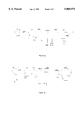
- FIG. 3a is a schematic diagram of the down converter used for the satellite broadcast signal receiving and distribution system according to the present invention.
- FIG. 3b is a schematic diagram of the up converter used for the satellite broadcast signal receiving and distribution system according to the present invention.
- FIG. 4 is a block diagram of the second embodiment of the satellite broadcast signal receiving and distribution system according to the present invention.
- FIG. 5 is a block diagram of the third embodiment of the satellite broadcast signal receiving and distribution system according to the present invention.
- the satellite system 10 of the present invention includes a receiving satellite 12 that will transmit signals (Vertical-polarized signals and Horizontal-polarized signals or left-hand circular and right-hand circular polarization signals) to a head-in equipment frequency processor 14. It is at this head-in equipment frequency processor 14 where the signals are received simultaneously and then transmitted via a single coaxial cable 16 to the head-out receiver processor 18. This will enable for the single coaxial cable 16 to transmit signals of two different polarities and frequencies simultaneously. From the head-out frequency processor the signals are reconverted to its original state and then transmitted to a source 20. As seen in FIG. 1, the two different polarities (Vertical-polarized signals and Horizontal-polarized signals or left-hand circular and right-hand circular polarization signals) are transported to the source via separate cables 22a and 22b, respectively.
- signals Very-polarized signals and Horizontal-polarized signals or left-hand circular and right-hand circular polarization signals
- the system of the present invention includes separate embodiments, and the first embodiment is illustrated in FIG. 2.
- a head-in frequency processor 14a couple to either a first head-out frequency processor 18a or a second head-out frequency processor 18b.
- FIG. 2 illustrates the head-in processor 14a to be coupled to two separate head-out processors 18a and 18b, respectively. This is shown for illustrative purposes only. In actuality, only one head-out receiver processor is utilized with the head-in processor 14a. The type and embodiment used for the head-out receiver processor is dependent to the combination of the satellite receiver and source that is utilized.
- the head-in equipment frequency processor 14a will receive two signals or two separate polarities and convert them to separate frequencies for enabling transmission via a single coaxial cable 16a.
- a low-noise block converter (LNB) 24 will receive the signals from the satellite 12.
- This LNB 24 is conventional and is used for amplifying the respective polarized signals (Vertical-polarized signals and Horizontal-polarized signals or left-hand circular and right-hand circular polarization signals). Accordingly, after signals are received, they pass the low-noise block converter 24, to provide for the signals to enter the head-in equipment frequency processor 14a (illustrated in FIG. 2 as dashed lines) via conduits 26a and 26b, respectively.
- the head-in equipment frequency processor 14a illustrated in FIG. 2, provides for the signals to be converted, via converters 28 and 30, to the frequencies which the present day amplifiers can transport.
- the object is to convert the signals of one polarity up (via converter 30) and to convert the signals of second polarity down (via converter 28). This will render the converted signals to be transmitted without emerging into the forbidden frequency conversion.
- the signals are transmitted to a first converter or down converter 28 and a second converter or up converter 30.
- These frequency converters, 28 and 30, respectively, convert the entered frequencies to a frequency which present day amplifies can transport.
- the converters will be discussed in further detail in FIGS. 3a and 3b.
- the utilization of two converters permit for the acceptance of two signals or polarized transponders that are of a different frequency.
- the transponder is converted down to a specified frequency.
- the specified frequency is the frequency that is required for the present day amplifiers for transportation.
- the newly converted frequencies are amplified through the amplifying means 32a.
- the converted frequencies are amplified so not to create second harmonics. These signals are then transferred to a conventional four way splitter 34a.
- the transponders are converted up to a specified frequency.
- the converted frequencies then are converted down via a down converter 36. This process of converting up and then down provides for frequencies to be converted without difficulties and avoiding the forbidden conversion area.
- the convert ed signals are transferred to the four way splitter 34a in ordered to combine the frequency of the amplified signal of 32a and frequency from converter 36.
- the frequencies from the phase lock loop (PLL) transmitter 38a are transmitted to the splitter 34a.
- the signals are passed through an AC power separator 40 which routes 60 Volts power to a DC power supply of 18 Volts. This will permit for the dual frequencies from the satellite dish 12 to be transmitted simultaneously via a single coaxial cable 16a.
- an optional conventional amplifier 42 can be coupled thereto. Power from a power source 44 is inserted into the lines via a power inserter 46. The signals are amplified, as needed, with additional amplifiers 48. It is noted that the amplifiers are optional and are dependent to the distance that the head-in frequency processor 14a is located from the head-out frequency processor 18a or 18b.
- the power supply and power source 11 en energizes the head-in frequency processor 14a.
- the signals are adjusted via a tap 50a to permit for the appropriate decibels that are required for the head-out processor 18a or 18b.
- the head-out frequency processor used for the head-in processor 14a illustrated in FIG. 1, can include two embodiments, dependent upon the embodiment for the source in combination with the satellite receiver.
- the first embodiment for the head-out frequency processor is illustrated in FIG. 2 by way of dash line 18a.
- the simultaneously transmitted signals enter the processor via conduit 16b.
- the conduit 16b is coupled to a conventional four (4) way splitter 34b.
- a conventional phase lock loop (PLL) receiver 56a is coupled to the splitter 34b to permit for the signals to be locked to the proper and desired frequencies.
- PLL phase lock loop
- From the splitter 34b the first frequency is transmitted to a first converter 58a in order to permit for the signals or transponders to be converted up to a specified frequency.
- This up converted signal from the first converter or up converter 58a is then transmitted to the satellite receiver by way of a conduit 22b.
- the second frequencies are transmitted to a first or up converter 52a and then are transported to a second or down converter 54a. This will permit for the signals to be converted to the desired frequency.
- This second or down converter is coupled to the satellite receiver 21 via conduit 22a.
- the signals from down converter 54a and from up converter 58a are in the original state, both frequency and polarity, when transmitted from the satellite to the head-in processor 14a, via lines 26a and 26b.
- the re-converted signals, frequencies and polarity in its original state are transmitted to the satellite receiver 21 via lines 22a and 22b.
- the satellite receiver 21 is coupled to a source 20 (illustrated as a television) to provide for proper transmission of the signals.
- the transmission line between the satellite receiver 21 and source 20 is illustrated but not labeled.
- the head-in processor converted the signals to different frequencies to enable the transmission of two separate polarized signals via a single co-axial cable to a head-out processor.
- the signals are re-converted to their original state, which was received via lines 26a and 26b.
- frequencies typically range between 950-1450 MHz. If the satellite transmits a frequency of 1450 for both the horizontal and vertical polarities, then one of the polarities, such as horizontal, is converted down to 560 MHz via converter 28. The second frequency of the second polarity, such as vertical, is first converted up to 2010 and then back down to 1070, via converters 30 and 36, respectively.
- Such a conversion allows for the two frequencies of two different polarities, 560 MHz (horizontal) and 1070 MHz (vertical), to be transmitted simultaneously on a single co-axial cable (16a and 16b).
- this head-out frequency processor is the reverse process of the head-in processor. This is to provide for the signals to reconverted to its original frequencies so as to provide for the satellite receiver 21 and source 20 to accept the signals.
- the single cable 16b accepts the signals at frequencies different than that of the source. Accordingly, the head-out processor must re-convert the signals to the frequencies that are utilized by the source 20.
- an alteration of the satellite receiver requires an alteration in the head-out receiver processor. This alteration is illustrated in FIG. 2 and is shown in outline designated as reference 18b.
- the satellite receiver utilizes only one wire and accepts only one type of signal, selectively, such as only left-hand circular or only right hand circular polarized signals.
- the frequencies are tapped via 50b.
- the tap 50b is coupled to the head-out processor 18b via line 16b which is connected to a four (4) way splitter 34c.
- the four way splitter is coupled to a phase lock loop (PLL) receiver 56b.
- PLL phase lock loop
- the first signal of a first polarity is transmitted to a first or up converted 52b and then is transmitted to a second or down converter 54b.
- the conversion of the signals from up to down provides the benefit of converting the frequency without any mishap or error. This method of conversion will avoid the forbidden conversion area as well as provide for the original received frequency and polarity of the signals.
- a polarity switch 60 is connected to converters 52b, 54b, and 58b for coupling the head-out processor to the satellite receiver via a single cable 22c and a joining means, which is a four way splitter 34d.
- the satellite receiver 21 is connected by way of a line (illustrated, but not labeled) to a source 20.
- the switch 60 is used to determine which polarity will enter into the head-out processor 18b.
- FIG. 3a represents the schematic rendering of the down converters (28, 36, 54a, and 54b)
- FIG. 3b represents the schematic rendering of the up converters (30, 52a, 52b, 58a, and 56b).
- the signal enters the down converter via line L1.
- the entered signal passes through a first capacitor C1 which is coupled to an amplifier AMP.
- the signal passes a second capacitor C2 before entering a first low pass filter LPF1.
- This first LPF1 is coupled to a mixer which is coupled to a second LPF2.
- This second LPF2 is connected to a third capacitor C3 which is coupled to a second choke CH2.
- the mixer is also connected to an oscillator OSC.
- the oscillator is coupled to a PPL.
- the first capacitor C1 is also connect to a first choke CH1.
- Capacitors C, C1, C2, C3 are coupled to the amplifier, oscillator, phase lock lope PPL, and the second low pass filter.
- Resistors R are coupled to the amplifier, oscillator, first low pass filter and mixer. Chokes are also coupled in series with capacitors to provide for the chokes to be parallel with the amplifier AMP and the second low pass filter, respectively. As seen the chokes CH1 and CH2 (inductors) and capacitors C are a DC bypass filter network and provide a DC path and enables passing DC power to the antenna electronics.
- the up converter is disclosed in FIG. 3b. As seen in this drawings, the signal enters the up converter via a first line L2.
- the converter further includes an amplifier AMP that is coupled to a first low pass filter LP1.
- the amplifier is also coupled to an oscillator OSC.
- the oscillator and the first low pass filter are connect to a mixer. This mixer is coupled to a high pass filter HPF.
- the oscillator is also connected with a phase lock loop receiver PLL.
- a second amplifier AMP2 is coupled to the high pass filter HPF.
- a second low pass filter LPF2 is coupled to the second amplifier.
- Capacitors are coupled to the first amplifier, first lower pass filter, and a the amplifier.
- Resistors R are coupled other first and second amplifiers, oscillator, first low pass filter, and mixer. Chokes are also used in this circuit.
- the first choke is coupled to a capacitor which is coupled to the first amplifier.
- the second chock is coupled to the phase lock loop.
- a low-noise block converter (LNB) 24 will receive the signals from the satellite 12.
- This LNB 24, as stated previously, is conventional and is used for amplifying the respective polarized signals (Vertical-polarized signals and Horizontal-polarized signals or left-hand circular and right-hand circular polarization signals). Hence, after signals are received, they pass the low-noise block converter 24, to provide for the signals to enter the head-in equipment frequency processor 14b (illustrated in FIG. 4 as dashed lines) via conduits 26a and 26b, respectively.
- the head-in equipment frequency processor 14b provides for the signals to be converted, via converters 28 and 30, as identified for the first embodiment. Thereby providing a system which includes frequencies that the present day amplifiers can transport.
- the object is to convert the signals of one polarity up (via converter 30) and to convert the signals of second polarization down (via converter 28).
- the signals are transmitted to a first converter or down converter 28 and a second converter or up converter 30.
- These frequency converters, 28 and 30, respectively, convert the entered frequencies to a frequency which present day amplifies can transport.
- the converters have been discussed in further detail in FIGS. 3a and 3b.
- the utilization of two converters permit for the acceptance of two signals or polarized transponders that are of a different frequency.
- the transponder is converted down to a specified frequency.
- the specified frequency is the frequency that is required for the present day amplifiers for transportation.
- the newly converted frequencies are amplified through the amplifying means, as illustrated in FIG. 2 via element 32a.
- the converted frequencies are amplified so not to create second harmonics. These signals are then transferred to a conventional two-way splitter 34c.
- the transponders are converted up to a specified frequency.
- the converted signals are transferred to the two way splitter 34c in order to combine the frequency of the amplified signals.
- the frequencies from the phase lock loop (PLL) transmitter 38a are transmitted to the splitter 34c.
- the signals are passed through a conventional tilt and gain 62. This will permit for the dual frequencies from the satellite dish 12 to be transmitted simultaneously via a single coaxial cable 16a.
- an optional conventional amplifier 42 can be coupled thereto. Power from a power source 44 is inserted into the lines via a power inserter 46. The signals are amplified, as needed, with additional amplifiers 48. It is noted that the amplifiers are optional and are dependent to the distance that the head-in frequency processor 14b is located from the head-out frequency processor 18c. The power supply and power source 11 energize the head-in frequency processor 14b.
- the signals are adjusted via a tap 50a to permit for the appropriate decibels that are required for the head-out processor 18c.
- the head-out frequency processor used for the head-in processor 14b is illustrated in by way of dash line 18c.
- the simultaneously transmitted signals enter the processor via conduit 16b.
- the conduit 16b is coupled to a conventional two (2) way splitter 34d.
- a conventional phase lock loop (PLL) receiver 56a is coupled to the splitter 34d to permit for the signals to be locked to the proper and desired frequencies.
- PLL phase lock loop
- From the splitter 34d the first frequency is transmitted to a first converter 52c in order to permit for the signals or transponders to be converted up to a specified frequency.
- the converted signals from the first converter or up converter 52c are then transmitted to the satellite receiver by way of a conduit 22a.
- the second frequencies are transmitted to a down converter 54c. This will permit for the signals to be converted to the desired frequency.
- This second or down converter is coupled to the satellite receiver 21 via conduit 22b.
- the signals from down converter 54c and from up converter 52c are in the original state, both frequency and polarity, when transmitted from the satellite to the head-in processor 14b, via lines 26a and 26b.
- the re-converted signals, frequencies and polarity in its original state, are transmitted to the satellite receiver 21 via lines 22a and 22b.
- the satellite receiver 21 is coupled to a source 20 (illustrated as a television) to provide for proper transmission of the signals.
- the transmission line between the satellite receiver 21 and source 20 is illustrated but not labeled.
- the head-in processor converted the signals to different frequencies to enable the transmission of two separate polarized signals via a single co-axial cable to a head-out processor. From the head-out processor, the signals are re-converted to their original state, which was received via lines 26a and 26b.
- the above identified embodiment is ideal for long distant use, i.e. exceeding 1000 feet. However, for shorter distance, i.e. less than 1000 feet, the components can be simplified again to provide for a device which is ideal for use in apartments or the like.
- the present invention includes the head-in equipment frequency processor 14c and the head-out frequency processor 18d.
- a low-noise block converter (LNB) 24 will receive the signals from the satellite 12.
- This LNB 24, as stated previously, is conventional and is used for amplifying the respective polarized signals (Vertical-polarized signals and Horizontal-polarized signals or left-hand circular and right-hand circular polarization signals). Hence, after signals are received, they pass the low-noise block converter 24, to provide for the signals to enter the head-in equipment frequency processor 14c (illustrated in FIG. 5 as dashed lines) via conduits 26a and 26b, respectively.
- this head-in equipment frequency processor 14c is simplified.
- the head-in equipment frequency processor 14c provides for signals of one frequency to be converted, up via converter 30, as identified for the first embodiment. Thereby providing a system which includes frequencies that the present day amplifiers can transport.
- the object is to convert the signals of one polarity up (via converter 30).
- the signal of the second polarity is amplified via conventional amplifier 32a.
- the signals are transmitted to a first converter or up converter 30 and a amplifier 32a.
- the down converters have been discussed in further detail in FIG. 3a.
- the signals are transferred to a conventional hybrid mixer 36a. From the mixer, the signals pass a diplexer 64. Signifies exit the diplexer via a single co-axial cable 16a.
- the signals can be adjusted via a tap (illustrated, but not labeled) to permit for the appropriate decibels that are required for the head-out processor 18d.
- the head-out frequency processor used for the head-in processor 14c is illustrated in by way of dash line 18d.
- the simultaneously transmitted signals enter the processor via conduit 16b.
- the conduit 16b is coupled to a conventional mixer 36b. From the mixer 36b the first frequency is transmitted to an amplifier 32b and the second frequency of a different polarity is transferred to a down converter 52d for converting the frequency to its original state.
- the re-converted signals, frequencies and polarity in its original state, is transmitted to the satellite receiver 21 via lines 22a and 22b.
- the satellite receiver 21 is coupled to a source 20 (illustrated as a television) to provide for proper transmission of the signals.
- the transmission line between the satellite receiver 21 and source 20 is illustrated but not labeled.
- the head-in processor converted the signals to different frequency to enable the transmission of two separate polarized signals via a single co-axial cable to a head-out processor. From the head-out processor, the signals are re-converted to their original state, which was received via lines 26a and 26b.
- the satellite system of the present invention will permit for two signals of different frequency and polarities to travel simultaneously via a single coaxial cable.
- the use of this will provide for a satellite system that is versatile, economical and compact.
- the usage of the single cable permits for a system that can accept satellite broadcasting in places that were previously render impossible. These places include mid/high-rise office buildings, condominiums, hospitals, schools, etc.
- the unique design and configuration enables the signals to be transmitted via the existing wiring of the buildings. The only renovations that may need to be done is the upgrading of the existing amplifiers.
Abstract
Description
Claims (6)
Priority Applications (17)
Application Number | Priority Date | Filing Date | Title |
---|---|---|---|
US08/838,677 US5805975A (en) | 1995-02-22 | 1997-04-09 | Satellite broadcast receiving and distribution system |
US09/001,484 US6122482A (en) | 1995-02-22 | 1997-12-31 | Satellite broadcast receiving and distribution system |
PCT/US1998/007153 WO1998048519A2 (en) | 1997-04-09 | 1998-04-08 | Satellite broadcast receiving and distribution system |
AU69621/98A AU6962198A (en) | 1997-04-09 | 1998-04-08 | Satellite broadcast receiving and distribution system |
US09/621,464 US6334045B1 (en) | 1995-02-22 | 2000-07-21 | Satellite broadcast receiving and distribution system |
US09/664,443 US6397038B1 (en) | 1995-02-22 | 2000-09-18 | Satellite broadcast receiving and distribution system |
US10/016,119 US6917783B2 (en) | 1995-02-22 | 2001-12-17 | Satellite broadcast receiving and distribution system |
US10/052,344 US6947702B2 (en) | 1995-02-22 | 2002-01-23 | Satellite broadcast receiving and distribution system |
US11/086,581 US20050176365A1 (en) | 1995-02-22 | 2005-03-23 | Satellite broadcast receiving and distribution system |
US11/089,131 US7542717B2 (en) | 1995-02-22 | 2005-03-24 | Satellite broadcast receiving and distribution system |
US12/314,439 US7826791B2 (en) | 1995-02-22 | 2008-12-10 | Satellite broadcast receiving and distribution system |
US12/464,969 US8165520B2 (en) | 1995-02-22 | 2009-05-13 | Satellite broadcast receiving and distribution system |
US12/874,318 US8095064B2 (en) | 1995-02-22 | 2010-09-02 | Satellite broadcast receiving and distribution system |
US13/310,379 US8666307B2 (en) | 1995-02-22 | 2011-12-02 | Satellite broadcast receiving and distribution system |
US13/422,614 US8583029B2 (en) | 1995-02-22 | 2012-03-16 | Satellite broadcast receiving and distribution system |
US14/051,242 US20140040961A1 (en) | 1995-02-22 | 2013-10-10 | Satellite broadcast receiving and distribution system |
US14/179,043 US20140162546A1 (en) | 1995-02-22 | 2014-02-12 | Satellite broadcast receiving and distribution system |
Applications Claiming Priority (2)
Application Number | Priority Date | Filing Date | Title |
---|---|---|---|
US39423495A | 1995-02-22 | 1995-02-22 | |
US08/838,677 US5805975A (en) | 1995-02-22 | 1997-04-09 | Satellite broadcast receiving and distribution system |
Related Parent Applications (2)
Application Number | Title | Priority Date | Filing Date |
---|---|---|---|
US39423495A Continuation-In-Part | 1995-02-22 | 1995-02-22 | |
US39423495A Continuation | 1995-02-22 | 1995-02-22 |
Related Child Applications (4)
Application Number | Title | Priority Date | Filing Date |
---|---|---|---|
US09/001,484 Continuation-In-Part US6122482A (en) | 1995-02-22 | 1997-12-31 | Satellite broadcast receiving and distribution system |
US09/001,484 Continuation US6122482A (en) | 1995-02-22 | 1997-12-31 | Satellite broadcast receiving and distribution system |
US10/052,344 Continuation US6947702B2 (en) | 1995-02-22 | 2002-01-23 | Satellite broadcast receiving and distribution system |
US11/089,131 Continuation US7542717B2 (en) | 1995-02-22 | 2005-03-24 | Satellite broadcast receiving and distribution system |
Publications (1)
Publication Number | Publication Date |
---|---|
US5805975A true US5805975A (en) | 1998-09-08 |
Family
ID=23558106
Family Applications (1)
Application Number | Title | Priority Date | Filing Date |
---|---|---|---|
US08/838,677 Expired - Lifetime US5805975A (en) | 1995-02-22 | 1997-04-09 | Satellite broadcast receiving and distribution system |
Country Status (1)
Country | Link |
---|---|
US (1) | US5805975A (en) |
Cited By (71)
Publication number | Priority date | Publication date | Assignee | Title |
---|---|---|---|---|
US5926744A (en) * | 1995-12-25 | 1999-07-20 | Sony Corporation | Receiving apparatus, receiving method, and terminal unit |
US5999795A (en) * | 1997-09-10 | 1999-12-07 | Starlink Inc. | RF GPS long cable driver |
US6023603A (en) * | 1996-11-01 | 2000-02-08 | Masprodenkoh Kabushikikaisha | Satellite signal splitter |
US6122482A (en) * | 1995-02-22 | 2000-09-19 | Global Communications, Inc. | Satellite broadcast receiving and distribution system |
WO2001017188A1 (en) * | 1999-09-01 | 2001-03-08 | Sony Electronics, Inc. | Receiver system and related method |
WO2002025847A1 (en) * | 2000-09-21 | 2002-03-28 | Zydonik Aaron E | Satellite television distribution system |
US6373445B1 (en) * | 1999-06-30 | 2002-04-16 | Masprodenkoh Kabushikikaisha | Converter for antenna to receive signals from two satellites |
WO2002051015A2 (en) * | 2000-12-19 | 2002-06-27 | Nokia Corporation | Improvements relating to satellite reception |
US6430233B1 (en) * | 1999-08-30 | 2002-08-06 | Hughes Electronics Corporation | Single-LNB satellite data receiver |
US6486907B1 (en) | 1997-01-07 | 2002-11-26 | Foxcom Ltd. | Satellite distributed television |
US6549754B1 (en) * | 1999-05-25 | 2003-04-15 | Rockwell Collins, Inc. | Passenger entertainment system having downconverter control signals and power supplied over output cables |
US20030119440A1 (en) * | 2001-12-21 | 2003-06-26 | Kumar Ramaswamy | Bi-directional communication apparatus |
US6600730B1 (en) * | 1998-08-20 | 2003-07-29 | Hughes Electronics Corporation | System for distribution of satellite signals from separate multiple satellites on a single cable line |
US20030163821A1 (en) * | 2002-02-26 | 2003-08-28 | Knutson Paul Gothard | Satellite television system ground station having wideband multi-channel LNB converter/transmitter architecture with controlled uplink transmission |
US20030163820A1 (en) * | 2002-02-26 | 2003-08-28 | Knutson Paul Gothard | Satellite television system ground station having wideband multi-channel LNB converter/transmitter architecture utilizing a frequency stabilized common oscillator |
US20030179723A1 (en) * | 2002-03-21 | 2003-09-25 | Abram Novak | Satellite signal distribution systems |
US20040060065A1 (en) * | 2002-09-25 | 2004-03-25 | James Thomas H. | Direct broadcast signal distribution methods |
US20060030259A1 (en) * | 2002-12-12 | 2006-02-09 | Herbert Hetzel | Dissemination system for satellite broadcasting |
US20060190967A1 (en) * | 2003-03-10 | 2006-08-24 | Pugel Michael A | Multi-channel satellite signal receiving apparatus |
US20060225102A1 (en) * | 2005-04-01 | 2006-10-05 | James Thomas H | Narrow bandwidth signal delivery system |
US20060225100A1 (en) * | 2005-04-01 | 2006-10-05 | James Thomas H | System architecture for control and signal distribution on coaxial cable |
US20060259929A1 (en) * | 2005-04-01 | 2006-11-16 | James Thomas H | Automatic level control for incoming signals of different signal strengths |
US20070082603A1 (en) * | 2005-10-12 | 2007-04-12 | John Norin | Triple band combining approach to satellite signal distribution |
DE10324122B4 (en) * | 2003-05-26 | 2007-08-30 | Smsc Europe Gmbh | Distribution system for satellite broadcasting |
US7383018B2 (en) | 2002-02-26 | 2008-06-03 | Thomas Licensing | Satellite television system ground station having wideband multi-channel LNB converter/transmitter architecture with coarse tuner in outdoor unit |
US7900230B2 (en) | 2005-04-01 | 2011-03-01 | The Directv Group, Inc. | Intelligent two-way switching network |
US7937732B2 (en) | 2005-09-02 | 2011-05-03 | The Directv Group, Inc. | Network fraud prevention via registration and verification |
US7950038B2 (en) | 2005-04-01 | 2011-05-24 | The Directv Group, Inc. | Transponder tuning and mapping |
US8019275B2 (en) | 2005-10-12 | 2011-09-13 | The Directv Group, Inc. | Band upconverter approach to KA/KU signal distribution |
US8024759B2 (en) | 2005-04-01 | 2011-09-20 | The Directv Group, Inc. | Backwards-compatible frequency translation module for satellite video delivery |
US8229383B2 (en) | 2009-01-06 | 2012-07-24 | The Directv Group, Inc. | Frequency drift estimation for low cost outdoor unit frequency conversions and system diagnostics |
US8238813B1 (en) | 2007-08-20 | 2012-08-07 | The Directv Group, Inc. | Computationally efficient design for broadcast satellite single wire and/or direct demod interface |
US8549565B2 (en) | 2005-04-01 | 2013-10-01 | The Directv Group, Inc. | Power balancing signal combiner |
US8621525B2 (en) * | 2005-04-01 | 2013-12-31 | The Directv Group, Inc. | Signal injection via power supply |
US8712318B2 (en) | 2007-05-29 | 2014-04-29 | The Directv Group, Inc. | Integrated multi-sat LNB and frequency translation module |
US8719875B2 (en) | 2006-11-06 | 2014-05-06 | The Directv Group, Inc. | Satellite television IP bitstream generator receiving unit |
US8789115B2 (en) | 2005-09-02 | 2014-07-22 | The Directv Group, Inc. | Frequency translation module discovery and configuration |
US9019929B2 (en) | 2006-12-19 | 2015-04-28 | Corning Optical Communications Wireless, Ltd. | Distributed antenna system for MIMO technologies |
US9112611B2 (en) | 2009-02-03 | 2015-08-18 | Corning Optical Communications LLC | Optical fiber-based distributed antenna systems, components, and related methods for calibration thereof |
US9178635B2 (en) | 2014-01-03 | 2015-11-03 | Corning Optical Communications Wireless Ltd | Separation of communication signal sub-bands in distributed antenna systems (DASs) to reduce interference |
US9184843B2 (en) | 2011-04-29 | 2015-11-10 | Corning Optical Communications LLC | Determining propagation delay of communications in distributed antenna systems, and related components, systems, and methods |
US9219879B2 (en) | 2009-11-13 | 2015-12-22 | Corning Optical Communications LLC | Radio-over-fiber (ROF) system for protocol-independent wired and/or wireless communication |
US9240835B2 (en) | 2011-04-29 | 2016-01-19 | Corning Optical Communications LLC | Systems, methods, and devices for increasing radio frequency (RF) power in distributed antenna systems |
US9247543B2 (en) | 2013-07-23 | 2016-01-26 | Corning Optical Communications Wireless Ltd | Monitoring non-supported wireless spectrum within coverage areas of distributed antenna systems (DASs) |
US9258052B2 (en) | 2012-03-30 | 2016-02-09 | Corning Optical Communications LLC | Reducing location-dependent interference in distributed antenna systems operating in multiple-input, multiple-output (MIMO) configuration, and related components, systems, and methods |
US9319138B2 (en) | 2010-02-15 | 2016-04-19 | Corning Optical Communications LLC | Dynamic cell bonding (DCB) for radio-over-fiber (RoF)-based networks and communication systems and related methods |
US9357551B2 (en) | 2014-05-30 | 2016-05-31 | Corning Optical Communications Wireless Ltd | Systems and methods for simultaneous sampling of serial digital data streams from multiple analog-to-digital converters (ADCS), including in distributed antenna systems |
US9385810B2 (en) | 2013-09-30 | 2016-07-05 | Corning Optical Communications Wireless Ltd | Connection mapping in distributed communication systems |
US9420542B2 (en) | 2014-09-25 | 2016-08-16 | Corning Optical Communications Wireless Ltd | System-wide uplink band gain control in a distributed antenna system (DAS), based on per band gain control of remote uplink paths in remote units |
US9455784B2 (en) | 2012-10-31 | 2016-09-27 | Corning Optical Communications Wireless Ltd | Deployable wireless infrastructures and methods of deploying wireless infrastructures |
US9525472B2 (en) | 2014-07-30 | 2016-12-20 | Corning Incorporated | Reducing location-dependent destructive interference in distributed antenna systems (DASS) operating in multiple-input, multiple-output (MIMO) configuration, and related components, systems, and methods |
US9531452B2 (en) | 2012-11-29 | 2016-12-27 | Corning Optical Communications LLC | Hybrid intra-cell / inter-cell remote unit antenna bonding in multiple-input, multiple-output (MIMO) distributed antenna systems (DASs) |
US9602210B2 (en) | 2014-09-24 | 2017-03-21 | Corning Optical Communications Wireless Ltd | Flexible head-end chassis supporting automatic identification and interconnection of radio interface modules and optical interface modules in an optical fiber-based distributed antenna system (DAS) |
US9621293B2 (en) | 2012-08-07 | 2017-04-11 | Corning Optical Communications Wireless Ltd | Distribution of time-division multiplexed (TDM) management services in a distributed antenna system, and related components, systems, and methods |
US9647758B2 (en) | 2012-11-30 | 2017-05-09 | Corning Optical Communications Wireless Ltd | Cabling connectivity monitoring and verification |
US9661781B2 (en) | 2013-07-31 | 2017-05-23 | Corning Optical Communications Wireless Ltd | Remote units for distributed communication systems and related installation methods and apparatuses |
US9673904B2 (en) | 2009-02-03 | 2017-06-06 | Corning Optical Communications LLC | Optical fiber-based distributed antenna systems, components, and related methods for calibration thereof |
US9681313B2 (en) | 2015-04-15 | 2017-06-13 | Corning Optical Communications Wireless Ltd | Optimizing remote antenna unit performance using an alternative data channel |
US9715157B2 (en) | 2013-06-12 | 2017-07-25 | Corning Optical Communications Wireless Ltd | Voltage controlled optical directional coupler |
US9730228B2 (en) | 2014-08-29 | 2017-08-08 | Corning Optical Communications Wireless Ltd | Individualized gain control of remote uplink band paths in a remote unit in a distributed antenna system (DAS), based on combined uplink power level in the remote unit |
US9729267B2 (en) | 2014-12-11 | 2017-08-08 | Corning Optical Communications Wireless Ltd | Multiplexing two separate optical links with the same wavelength using asymmetric combining and splitting |
US9775123B2 (en) | 2014-03-28 | 2017-09-26 | Corning Optical Communications Wireless Ltd. | Individualized gain control of uplink paths in remote units in a distributed antenna system (DAS) based on individual remote unit contribution to combined uplink power |
US9807700B2 (en) | 2015-02-19 | 2017-10-31 | Corning Optical Communications Wireless Ltd | Offsetting unwanted downlink interference signals in an uplink path in a distributed antenna system (DAS) |
US9942618B2 (en) | 2007-10-31 | 2018-04-10 | The Directv Group, Inc. | SMATV headend using IP transport stream input and method for operating the same |
US9948349B2 (en) | 2015-07-17 | 2018-04-17 | Corning Optical Communications Wireless Ltd | IOT automation and data collection system |
US9974074B2 (en) | 2013-06-12 | 2018-05-15 | Corning Optical Communications Wireless Ltd | Time-division duplexing (TDD) in distributed communications systems, including distributed antenna systems (DASs) |
US10128951B2 (en) | 2009-02-03 | 2018-11-13 | Corning Optical Communications LLC | Optical fiber-based distributed antenna systems, components, and related methods for monitoring and configuring thereof |
US10136200B2 (en) | 2012-04-25 | 2018-11-20 | Corning Optical Communications LLC | Distributed antenna system architectures |
US10236924B2 (en) | 2016-03-31 | 2019-03-19 | Corning Optical Communications Wireless Ltd | Reducing out-of-channel noise in a wireless distribution system (WDS) |
US10560214B2 (en) | 2015-09-28 | 2020-02-11 | Corning Optical Communications LLC | Downlink and uplink communication path switching in a time-division duplex (TDD) distributed antenna system (DAS) |
US11671914B2 (en) | 2010-10-13 | 2023-06-06 | Corning Optical Communications LLC | Power management for remote antenna units in distributed antenna systems |
Citations (4)
Publication number | Priority date | Publication date | Assignee | Title |
---|---|---|---|---|
US4509198A (en) * | 1981-10-19 | 1985-04-02 | Dx Antenna Company, Limited | Satellite broadcast signal receiving system |
US4761827A (en) * | 1984-09-17 | 1988-08-02 | Satellite Technology Services, Inc. | Polarity switch for satellite television receiver |
JPH02140022A (en) * | 1988-11-18 | 1990-05-29 | Maspro Denkoh Corp | Satellite signal reception system |
DE4126774A1 (en) * | 1991-08-13 | 1993-02-18 | Kathrein Werke Kg | Converter for Astra satellite signal reception - selects two local oscillator frequencies so that second or third order mixing products fall between channels |
-
1997
- 1997-04-09 US US08/838,677 patent/US5805975A/en not_active Expired - Lifetime
Patent Citations (4)
Publication number | Priority date | Publication date | Assignee | Title |
---|---|---|---|---|
US4509198A (en) * | 1981-10-19 | 1985-04-02 | Dx Antenna Company, Limited | Satellite broadcast signal receiving system |
US4761827A (en) * | 1984-09-17 | 1988-08-02 | Satellite Technology Services, Inc. | Polarity switch for satellite television receiver |
JPH02140022A (en) * | 1988-11-18 | 1990-05-29 | Maspro Denkoh Corp | Satellite signal reception system |
DE4126774A1 (en) * | 1991-08-13 | 1993-02-18 | Kathrein Werke Kg | Converter for Astra satellite signal reception - selects two local oscillator frequencies so that second or third order mixing products fall between channels |
Cited By (133)
Publication number | Priority date | Publication date | Assignee | Title |
---|---|---|---|---|
US20090282442A1 (en) * | 1995-02-22 | 2009-11-12 | Global Communications, Inc. | Satellite broadcast receiving and distribution system |
US8666307B2 (en) | 1995-02-22 | 2014-03-04 | Global Communications, Inc. | Satellite broadcast receiving and distribution system |
US6917783B2 (en) * | 1995-02-22 | 2005-07-12 | Global Communications, Inc. | Satellite broadcast receiving and distribution system |
US6122482A (en) * | 1995-02-22 | 2000-09-19 | Global Communications, Inc. | Satellite broadcast receiving and distribution system |
US7542717B2 (en) | 1995-02-22 | 2009-06-02 | Global Communications, Inc. | Satellite broadcast receiving and distribution system |
US8095064B2 (en) | 1995-02-22 | 2012-01-10 | Global Communications, Inc. | Satellite broadcast receiving and distribution system |
US6334045B1 (en) * | 1995-02-22 | 2001-12-25 | Global Communications, Inc. | Satellite broadcast receiving and distribution system |
US20050176365A1 (en) * | 1995-02-22 | 2005-08-11 | Global Communications, Inc. | Satellite broadcast receiving and distribution system |
US6947702B2 (en) | 1995-02-22 | 2005-09-20 | Global Communications, Inc. | Satellite broadcast receiving and distribution system |
US6397038B1 (en) * | 1995-02-22 | 2002-05-28 | Global Communications, Inc. | Satellite broadcast receiving and distribution system |
US7826791B2 (en) * | 1995-02-22 | 2010-11-02 | Global Communications, Inc. | Satellite broadcast receiving and distribution system |
US20020094775A1 (en) * | 1995-02-22 | 2002-07-18 | Global Communications, Inc. | Satellite broadcast receiving and distribution system |
US20050221756A1 (en) * | 1995-02-22 | 2005-10-06 | Global Communications, Inc. | Satellite broadcast receiving and distribution system |
US20110197235A1 (en) * | 1995-02-22 | 2011-08-11 | Global Communications, Inc. | Satellite broadcast receiving and distribution system |
US8165520B2 (en) | 1995-02-22 | 2012-04-24 | Global Communications, Inc. | Satellite broadcast receiving and distribution system |
US20030040270A1 (en) * | 1995-02-22 | 2003-02-27 | Global Communications, Inc. | Satellite broadcast receiving and distribution system |
US8583029B2 (en) | 1995-02-22 | 2013-11-12 | Global Communications, Inc. | Satellite broadcast receiving and distribution system |
US5926744A (en) * | 1995-12-25 | 1999-07-20 | Sony Corporation | Receiving apparatus, receiving method, and terminal unit |
KR100445108B1 (en) * | 1995-12-25 | 2004-11-06 | 소니 가부시끼 가이샤 | Receiver, Receiving Method and Terminal Device |
US6023603A (en) * | 1996-11-01 | 2000-02-08 | Masprodenkoh Kabushikikaisha | Satellite signal splitter |
US6486907B1 (en) | 1997-01-07 | 2002-11-26 | Foxcom Ltd. | Satellite distributed television |
US5999795A (en) * | 1997-09-10 | 1999-12-07 | Starlink Inc. | RF GPS long cable driver |
US6600730B1 (en) * | 1998-08-20 | 2003-07-29 | Hughes Electronics Corporation | System for distribution of satellite signals from separate multiple satellites on a single cable line |
US6549754B1 (en) * | 1999-05-25 | 2003-04-15 | Rockwell Collins, Inc. | Passenger entertainment system having downconverter control signals and power supplied over output cables |
US6373445B1 (en) * | 1999-06-30 | 2002-04-16 | Masprodenkoh Kabushikikaisha | Converter for antenna to receive signals from two satellites |
US6430233B1 (en) * | 1999-08-30 | 2002-08-06 | Hughes Electronics Corporation | Single-LNB satellite data receiver |
WO2001017188A1 (en) * | 1999-09-01 | 2001-03-08 | Sony Electronics, Inc. | Receiver system and related method |
US6205185B1 (en) * | 1999-09-01 | 2001-03-20 | Sony Corporation Of Japan | Self configuring multi-dwelling satellite receiver system |
WO2002025847A1 (en) * | 2000-09-21 | 2002-03-28 | Zydonik Aaron E | Satellite television distribution system |
CN1309191C (en) * | 2000-12-19 | 2007-04-04 | 诺基亚有限公司 | Improvements relating to satellite reception |
WO2002051015A2 (en) * | 2000-12-19 | 2002-06-27 | Nokia Corporation | Improvements relating to satellite reception |
WO2002051015A3 (en) * | 2000-12-19 | 2002-09-19 | Nokia Corp | Improvements relating to satellite reception |
US20040058642A1 (en) * | 2000-12-19 | 2004-03-25 | Lauri Merio | Satellite reception |
US7245892B2 (en) | 2000-12-19 | 2007-07-17 | Nokia Corporation | Satellite reception |
US7428403B2 (en) | 2001-12-21 | 2008-09-23 | Thomson Licensing | Bi-directional communication apparatus |
US20030119440A1 (en) * | 2001-12-21 | 2003-06-26 | Kumar Ramaswamy | Bi-directional communication apparatus |
US20030163821A1 (en) * | 2002-02-26 | 2003-08-28 | Knutson Paul Gothard | Satellite television system ground station having wideband multi-channel LNB converter/transmitter architecture with controlled uplink transmission |
US8418210B2 (en) | 2002-02-26 | 2013-04-09 | Thomson Licensing | Satellite television system ground station having wideband multi-channel LNB converter/transmitter architecture with controlled uplink transmission |
US20030163820A1 (en) * | 2002-02-26 | 2003-08-28 | Knutson Paul Gothard | Satellite television system ground station having wideband multi-channel LNB converter/transmitter architecture utilizing a frequency stabilized common oscillator |
US7383018B2 (en) | 2002-02-26 | 2008-06-03 | Thomas Licensing | Satellite television system ground station having wideband multi-channel LNB converter/transmitter architecture with coarse tuner in outdoor unit |
US7401349B2 (en) | 2002-02-26 | 2008-07-15 | Thomson Licensing | Satellite television system ground station having wideband multi-channel LNB converter/transmitter architecture utilizing a frequency stabilized common oscillator |
US7352991B2 (en) | 2002-03-21 | 2008-04-01 | National Antenna Systems | Satellite signal distribution systems |
US20030179723A1 (en) * | 2002-03-21 | 2003-09-25 | Abram Novak | Satellite signal distribution systems |
US7954127B2 (en) | 2002-09-25 | 2011-05-31 | The Directv Group, Inc. | Direct broadcast signal distribution methods |
US20040060065A1 (en) * | 2002-09-25 | 2004-03-25 | James Thomas H. | Direct broadcast signal distribution methods |
US7502588B2 (en) | 2002-12-12 | 2009-03-10 | Smsc Europe Gmbh | Dissemination system for satellite broadcasting |
US20060030259A1 (en) * | 2002-12-12 | 2006-02-09 | Herbert Hetzel | Dissemination system for satellite broadcasting |
US20060190967A1 (en) * | 2003-03-10 | 2006-08-24 | Pugel Michael A | Multi-channel satellite signal receiving apparatus |
DE10324122B4 (en) * | 2003-05-26 | 2007-08-30 | Smsc Europe Gmbh | Distribution system for satellite broadcasting |
US20060225100A1 (en) * | 2005-04-01 | 2006-10-05 | James Thomas H | System architecture for control and signal distribution on coaxial cable |
US20060259929A1 (en) * | 2005-04-01 | 2006-11-16 | James Thomas H | Automatic level control for incoming signals of different signal strengths |
US7958531B2 (en) | 2005-04-01 | 2011-06-07 | The Directv Group, Inc. | Automatic level control for incoming signals of different signal strengths |
US7987486B2 (en) | 2005-04-01 | 2011-07-26 | The Directv Group, Inc. | System architecture for control and signal distribution on coaxial cable |
US8621525B2 (en) * | 2005-04-01 | 2013-12-31 | The Directv Group, Inc. | Signal injection via power supply |
US7945932B2 (en) | 2005-04-01 | 2011-05-17 | The Directv Group, Inc. | Narrow bandwidth signal delivery system |
US20060225102A1 (en) * | 2005-04-01 | 2006-10-05 | James Thomas H | Narrow bandwidth signal delivery system |
US8024759B2 (en) | 2005-04-01 | 2011-09-20 | The Directv Group, Inc. | Backwards-compatible frequency translation module for satellite video delivery |
US8549565B2 (en) | 2005-04-01 | 2013-10-01 | The Directv Group, Inc. | Power balancing signal combiner |
US7900230B2 (en) | 2005-04-01 | 2011-03-01 | The Directv Group, Inc. | Intelligent two-way switching network |
US7950038B2 (en) | 2005-04-01 | 2011-05-24 | The Directv Group, Inc. | Transponder tuning and mapping |
US8789115B2 (en) | 2005-09-02 | 2014-07-22 | The Directv Group, Inc. | Frequency translation module discovery and configuration |
US7937732B2 (en) | 2005-09-02 | 2011-05-03 | The Directv Group, Inc. | Network fraud prevention via registration and verification |
US20070082603A1 (en) * | 2005-10-12 | 2007-04-12 | John Norin | Triple band combining approach to satellite signal distribution |
US8019275B2 (en) | 2005-10-12 | 2011-09-13 | The Directv Group, Inc. | Band upconverter approach to KA/KU signal distribution |
US7991348B2 (en) | 2005-10-12 | 2011-08-02 | The Directv Group, Inc. | Triple band combining approach to satellite signal distribution |
US8719875B2 (en) | 2006-11-06 | 2014-05-06 | The Directv Group, Inc. | Satellite television IP bitstream generator receiving unit |
US9130613B2 (en) | 2006-12-19 | 2015-09-08 | Corning Optical Communications Wireless Ltd | Distributed antenna system for MIMO technologies |
US9432095B2 (en) | 2006-12-19 | 2016-08-30 | Corning Optical Communications Wireless Ltd | Distributed antenna system for MIMO technologies |
US9300372B2 (en) | 2006-12-19 | 2016-03-29 | Corning Optical Communications Wireless Ltd | Distributed antenna system for MIMO technologies |
US9019929B2 (en) | 2006-12-19 | 2015-04-28 | Corning Optical Communications Wireless, Ltd. | Distributed antenna system for MIMO technologies |
US9461719B2 (en) | 2006-12-19 | 2016-10-04 | Corning Optical Communications Wirless Ltd | Distributed antenna system for MIMO technologies |
US8712318B2 (en) | 2007-05-29 | 2014-04-29 | The Directv Group, Inc. | Integrated multi-sat LNB and frequency translation module |
US8238813B1 (en) | 2007-08-20 | 2012-08-07 | The Directv Group, Inc. | Computationally efficient design for broadcast satellite single wire and/or direct demod interface |
US9942618B2 (en) | 2007-10-31 | 2018-04-10 | The Directv Group, Inc. | SMATV headend using IP transport stream input and method for operating the same |
US8229383B2 (en) | 2009-01-06 | 2012-07-24 | The Directv Group, Inc. | Frequency drift estimation for low cost outdoor unit frequency conversions and system diagnostics |
US9900097B2 (en) | 2009-02-03 | 2018-02-20 | Corning Optical Communications LLC | Optical fiber-based distributed antenna systems, components, and related methods for calibration thereof |
US9673904B2 (en) | 2009-02-03 | 2017-06-06 | Corning Optical Communications LLC | Optical fiber-based distributed antenna systems, components, and related methods for calibration thereof |
US10153841B2 (en) | 2009-02-03 | 2018-12-11 | Corning Optical Communications LLC | Optical fiber-based distributed antenna systems, components, and related methods for calibration thereof |
US10128951B2 (en) | 2009-02-03 | 2018-11-13 | Corning Optical Communications LLC | Optical fiber-based distributed antenna systems, components, and related methods for monitoring and configuring thereof |
US9112611B2 (en) | 2009-02-03 | 2015-08-18 | Corning Optical Communications LLC | Optical fiber-based distributed antenna systems, components, and related methods for calibration thereof |
US9219879B2 (en) | 2009-11-13 | 2015-12-22 | Corning Optical Communications LLC | Radio-over-fiber (ROF) system for protocol-independent wired and/or wireless communication |
US9729238B2 (en) | 2009-11-13 | 2017-08-08 | Corning Optical Communications LLC | Radio-over-fiber (ROF) system for protocol-independent wired and/or wireless communication |
US9485022B2 (en) | 2009-11-13 | 2016-11-01 | Corning Optical Communications LLC | Radio-over-fiber (ROF) system for protocol-independent wired and/or wireless communication |
US9319138B2 (en) | 2010-02-15 | 2016-04-19 | Corning Optical Communications LLC | Dynamic cell bonding (DCB) for radio-over-fiber (RoF)-based networks and communication systems and related methods |
US11671914B2 (en) | 2010-10-13 | 2023-06-06 | Corning Optical Communications LLC | Power management for remote antenna units in distributed antenna systems |
US9240835B2 (en) | 2011-04-29 | 2016-01-19 | Corning Optical Communications LLC | Systems, methods, and devices for increasing radio frequency (RF) power in distributed antenna systems |
US9807722B2 (en) | 2011-04-29 | 2017-10-31 | Corning Optical Communications LLC | Determining propagation delay of communications in distributed antenna systems, and related components, systems, and methods |
US10148347B2 (en) | 2011-04-29 | 2018-12-04 | Corning Optical Communications LLC | Systems, methods, and devices for increasing radio frequency (RF) power in distributed antenna systems |
US9369222B2 (en) | 2011-04-29 | 2016-06-14 | Corning Optical Communications LLC | Determining propagation delay of communications in distributed antenna systems, and related components, systems, and methods |
US9184843B2 (en) | 2011-04-29 | 2015-11-10 | Corning Optical Communications LLC | Determining propagation delay of communications in distributed antenna systems, and related components, systems, and methods |
US9806797B2 (en) | 2011-04-29 | 2017-10-31 | Corning Optical Communications LLC | Systems, methods, and devices for increasing radio frequency (RF) power in distributed antenna systems |
US9258052B2 (en) | 2012-03-30 | 2016-02-09 | Corning Optical Communications LLC | Reducing location-dependent interference in distributed antenna systems operating in multiple-input, multiple-output (MIMO) configuration, and related components, systems, and methods |
US9813127B2 (en) | 2012-03-30 | 2017-11-07 | Corning Optical Communications LLC | Reducing location-dependent interference in distributed antenna systems operating in multiple-input, multiple-output (MIMO) configuration, and related components, systems, and methods |
US10136200B2 (en) | 2012-04-25 | 2018-11-20 | Corning Optical Communications LLC | Distributed antenna system architectures |
US10349156B2 (en) | 2012-04-25 | 2019-07-09 | Corning Optical Communications LLC | Distributed antenna system architectures |
US9621293B2 (en) | 2012-08-07 | 2017-04-11 | Corning Optical Communications Wireless Ltd | Distribution of time-division multiplexed (TDM) management services in a distributed antenna system, and related components, systems, and methods |
US9973968B2 (en) | 2012-08-07 | 2018-05-15 | Corning Optical Communications Wireless Ltd | Distribution of time-division multiplexed (TDM) management services in a distributed antenna system, and related components, systems, and methods |
US9455784B2 (en) | 2012-10-31 | 2016-09-27 | Corning Optical Communications Wireless Ltd | Deployable wireless infrastructures and methods of deploying wireless infrastructures |
US9531452B2 (en) | 2012-11-29 | 2016-12-27 | Corning Optical Communications LLC | Hybrid intra-cell / inter-cell remote unit antenna bonding in multiple-input, multiple-output (MIMO) distributed antenna systems (DASs) |
US9647758B2 (en) | 2012-11-30 | 2017-05-09 | Corning Optical Communications Wireless Ltd | Cabling connectivity monitoring and verification |
US10361782B2 (en) | 2012-11-30 | 2019-07-23 | Corning Optical Communications LLC | Cabling connectivity monitoring and verification |
US9974074B2 (en) | 2013-06-12 | 2018-05-15 | Corning Optical Communications Wireless Ltd | Time-division duplexing (TDD) in distributed communications systems, including distributed antenna systems (DASs) |
US11291001B2 (en) | 2013-06-12 | 2022-03-29 | Corning Optical Communications LLC | Time-division duplexing (TDD) in distributed communications systems, including distributed antenna systems (DASs) |
US9715157B2 (en) | 2013-06-12 | 2017-07-25 | Corning Optical Communications Wireless Ltd | Voltage controlled optical directional coupler |
US11792776B2 (en) | 2013-06-12 | 2023-10-17 | Corning Optical Communications LLC | Time-division duplexing (TDD) in distributed communications systems, including distributed antenna systems (DASs) |
US10292056B2 (en) | 2013-07-23 | 2019-05-14 | Corning Optical Communications LLC | Monitoring non-supported wireless spectrum within coverage areas of distributed antenna systems (DASs) |
US9247543B2 (en) | 2013-07-23 | 2016-01-26 | Corning Optical Communications Wireless Ltd | Monitoring non-supported wireless spectrum within coverage areas of distributed antenna systems (DASs) |
US9526020B2 (en) | 2013-07-23 | 2016-12-20 | Corning Optical Communications Wireless Ltd | Monitoring non-supported wireless spectrum within coverage areas of distributed antenna systems (DASs) |
US9967754B2 (en) | 2013-07-23 | 2018-05-08 | Corning Optical Communications Wireless Ltd | Monitoring non-supported wireless spectrum within coverage areas of distributed antenna systems (DASs) |
US9661781B2 (en) | 2013-07-31 | 2017-05-23 | Corning Optical Communications Wireless Ltd | Remote units for distributed communication systems and related installation methods and apparatuses |
US9385810B2 (en) | 2013-09-30 | 2016-07-05 | Corning Optical Communications Wireless Ltd | Connection mapping in distributed communication systems |
US9178635B2 (en) | 2014-01-03 | 2015-11-03 | Corning Optical Communications Wireless Ltd | Separation of communication signal sub-bands in distributed antenna systems (DASs) to reduce interference |
US9775123B2 (en) | 2014-03-28 | 2017-09-26 | Corning Optical Communications Wireless Ltd. | Individualized gain control of uplink paths in remote units in a distributed antenna system (DAS) based on individual remote unit contribution to combined uplink power |
US9807772B2 (en) | 2014-05-30 | 2017-10-31 | Corning Optical Communications Wireless Ltd. | Systems and methods for simultaneous sampling of serial digital data streams from multiple analog-to-digital converters (ADCs), including in distributed antenna systems |
US9357551B2 (en) | 2014-05-30 | 2016-05-31 | Corning Optical Communications Wireless Ltd | Systems and methods for simultaneous sampling of serial digital data streams from multiple analog-to-digital converters (ADCS), including in distributed antenna systems |
US10256879B2 (en) | 2014-07-30 | 2019-04-09 | Corning Incorporated | Reducing location-dependent destructive interference in distributed antenna systems (DASS) operating in multiple-input, multiple-output (MIMO) configuration, and related components, systems, and methods |
US9525472B2 (en) | 2014-07-30 | 2016-12-20 | Corning Incorporated | Reducing location-dependent destructive interference in distributed antenna systems (DASS) operating in multiple-input, multiple-output (MIMO) configuration, and related components, systems, and methods |
US9929786B2 (en) | 2014-07-30 | 2018-03-27 | Corning Incorporated | Reducing location-dependent destructive interference in distributed antenna systems (DASS) operating in multiple-input, multiple-output (MIMO) configuration, and related components, systems, and methods |
US9730228B2 (en) | 2014-08-29 | 2017-08-08 | Corning Optical Communications Wireless Ltd | Individualized gain control of remote uplink band paths in a remote unit in a distributed antenna system (DAS), based on combined uplink power level in the remote unit |
US10397929B2 (en) | 2014-08-29 | 2019-08-27 | Corning Optical Communications LLC | Individualized gain control of remote uplink band paths in a remote unit in a distributed antenna system (DAS), based on combined uplink power level in the remote unit |
US9929810B2 (en) | 2014-09-24 | 2018-03-27 | Corning Optical Communications Wireless Ltd | Flexible head-end chassis supporting automatic identification and interconnection of radio interface modules and optical interface modules in an optical fiber-based distributed antenna system (DAS) |
US9602210B2 (en) | 2014-09-24 | 2017-03-21 | Corning Optical Communications Wireless Ltd | Flexible head-end chassis supporting automatic identification and interconnection of radio interface modules and optical interface modules in an optical fiber-based distributed antenna system (DAS) |
US9420542B2 (en) | 2014-09-25 | 2016-08-16 | Corning Optical Communications Wireless Ltd | System-wide uplink band gain control in a distributed antenna system (DAS), based on per band gain control of remote uplink paths in remote units |
US9788279B2 (en) | 2014-09-25 | 2017-10-10 | Corning Optical Communications Wireless Ltd | System-wide uplink band gain control in a distributed antenna system (DAS), based on per-band gain control of remote uplink paths in remote units |
US10135561B2 (en) | 2014-12-11 | 2018-11-20 | Corning Optical Communications Wireless Ltd | Multiplexing two separate optical links with the same wavelength using asymmetric combining and splitting |
US9729267B2 (en) | 2014-12-11 | 2017-08-08 | Corning Optical Communications Wireless Ltd | Multiplexing two separate optical links with the same wavelength using asymmetric combining and splitting |
US10292114B2 (en) | 2015-02-19 | 2019-05-14 | Corning Optical Communications LLC | Offsetting unwanted downlink interference signals in an uplink path in a distributed antenna system (DAS) |
US9807700B2 (en) | 2015-02-19 | 2017-10-31 | Corning Optical Communications Wireless Ltd | Offsetting unwanted downlink interference signals in an uplink path in a distributed antenna system (DAS) |
US9681313B2 (en) | 2015-04-15 | 2017-06-13 | Corning Optical Communications Wireless Ltd | Optimizing remote antenna unit performance using an alternative data channel |
US10009094B2 (en) | 2015-04-15 | 2018-06-26 | Corning Optical Communications Wireless Ltd | Optimizing remote antenna unit performance using an alternative data channel |
US9948349B2 (en) | 2015-07-17 | 2018-04-17 | Corning Optical Communications Wireless Ltd | IOT automation and data collection system |
US10560214B2 (en) | 2015-09-28 | 2020-02-11 | Corning Optical Communications LLC | Downlink and uplink communication path switching in a time-division duplex (TDD) distributed antenna system (DAS) |
US10236924B2 (en) | 2016-03-31 | 2019-03-19 | Corning Optical Communications Wireless Ltd | Reducing out-of-channel noise in a wireless distribution system (WDS) |
Similar Documents
Publication | Publication Date | Title |
---|---|---|
US5805975A (en) | Satellite broadcast receiving and distribution system | |
US8095064B2 (en) | Satellite broadcast receiving and distribution system | |
US6430742B1 (en) | Device for distributing television signals by cable | |
TW432830B (en) | System for distribution of satellite signals from separate multiple satellites on a single cable line | |
CN1003763B (en) | Satellite/hybrid television system | |
JPH10135858A (en) | Satellite signal distributer | |
GB2377111A (en) | Secure operation of multiple set top boxes for braodcast data receivers | |
JPS604633B2 (en) | cable television system | |
JPH10303798A (en) | Signal distribution processing method/system | |
JPH11355738A (en) | Frequency converter for two-way catv system and in-house transmission system for multiple dwelling house | |
JP2573659B2 (en) | Shared listening system | |
KR900002328B1 (en) | Multiple transmission method and receive arrangement for high frequency and low frequency audio signal | |
JPS63310234A (en) | Disaster preventing administrative radio community reception system | |
JPS60160283A (en) | Reverse signal transmitter of cable television system | |
JP2934177B2 (en) | Interactive TV listening facility | |
US1815833A (en) | Subdivided service system of radio broadcast distribution | |
JP2001086020A (en) | Satellite wave conversion device | |
US20030061616A1 (en) | Re-broadcasting systems and methods using automatic gain control | |
Callahan Jr | The Design, Implementation and Operation of Bidirectional Wideband CATV Networks for Two-Way Video Audio and Data Services | |
JPH10336481A (en) | Common reception system | |
Galuska | Translators as television broadcast repeaters | |
JPS60160281A (en) | Signal transmission processing unit for cable television system | |
JPH11298809A (en) | Satellite signal reception system, signal distribution changeover device and amplifier | |
JPS60160285A (en) | Emergency information transmitter of cable television system | |
JPS5856542A (en) | Wire broadcasting system |
Legal Events
Date | Code | Title | Description |
---|---|---|---|
STCF | Information on status: patent grant |
Free format text: PATENTED CASE |
|
AS | Assignment |
Owner name: GLOBAL COMMUNICATIONS, INC., FLORIDA Free format text: ASSIGNMENT OF ASSIGNORS INTEREST;ASSIGNORS:GREEN, JAMES A. SR.;COKER, AUSTIN S. JR.;REEL/FRAME:010881/0842 Effective date: 20000630 |
|
FEPP | Fee payment procedure |
Free format text: PAT HOLDER NO LONGER CLAIMS SMALL ENTITY STATUS, ENTITY STATUS SET TO UNDISCOUNTED (ORIGINAL EVENT CODE: STOL); ENTITY STATUS OF PATENT OWNER: LARGE ENTITY |
|
FPAY | Fee payment |
Year of fee payment: 4 |
|
SULP | Surcharge for late payment | ||
FEPP | Fee payment procedure |
Free format text: ENTITY STATUS SET TO UNDISCOUNTED (ORIGINAL EVENT CODE: BIG.); ENTITY STATUS OF PATENT OWNER: LARGE ENTITY |
|
AS | Assignment |
Owner name: GLOBAL COMMUNICATIONS, INC., FLORIDA Free format text: QUITCLAIM DEED AND RELEASE;ASSIGNOR:GREEN, JAMES A.;REEL/FRAME:016522/0100 Effective date: 20041005 |
|
FPAY | Fee payment |
Year of fee payment: 8 |
|
FPAY | Fee payment |
Year of fee payment: 12 |