US5807124A - Card connector with switch - Google Patents
Card connector with switch Download PDFInfo
- Publication number
- US5807124A US5807124A US08/986,857 US98685797A US5807124A US 5807124 A US5807124 A US 5807124A US 98685797 A US98685797 A US 98685797A US 5807124 A US5807124 A US 5807124A
- Authority
- US
- United States
- Prior art keywords
- body portion
- switch
- contact body
- card
- contact
- Prior art date
- Legal status (The legal status is an assumption and is not a legal conclusion. Google has not performed a legal analysis and makes no representation as to the accuracy of the status listed.)
- Expired - Lifetime
Links
Images


Classifications
-
- G—PHYSICS
- G06—COMPUTING; CALCULATING OR COUNTING
- G06K—GRAPHICAL DATA READING; PRESENTATION OF DATA; RECORD CARRIERS; HANDLING RECORD CARRIERS
- G06K7/00—Methods or arrangements for sensing record carriers, e.g. for reading patterns
- G06K7/0013—Methods or arrangements for sensing record carriers, e.g. for reading patterns by galvanic contacts, e.g. card connectors for ISO-7816 compliant smart cards or memory cards, e.g. SD card readers
- G06K7/0021—Methods or arrangements for sensing record carriers, e.g. for reading patterns by galvanic contacts, e.g. card connectors for ISO-7816 compliant smart cards or memory cards, e.g. SD card readers for reading/sensing record carriers having surface contacts
-
- G—PHYSICS
- G06—COMPUTING; CALCULATING OR COUNTING
- G06K—GRAPHICAL DATA READING; PRESENTATION OF DATA; RECORD CARRIERS; HANDLING RECORD CARRIERS
- G06K7/00—Methods or arrangements for sensing record carriers, e.g. for reading patterns
- G06K7/0013—Methods or arrangements for sensing record carriers, e.g. for reading patterns by galvanic contacts, e.g. card connectors for ISO-7816 compliant smart cards or memory cards, e.g. SD card readers
- G06K7/0056—Methods or arrangements for sensing record carriers, e.g. for reading patterns by galvanic contacts, e.g. card connectors for ISO-7816 compliant smart cards or memory cards, e.g. SD card readers housing of the card connector
- G06K7/0069—Methods or arrangements for sensing record carriers, e.g. for reading patterns by galvanic contacts, e.g. card connectors for ISO-7816 compliant smart cards or memory cards, e.g. SD card readers housing of the card connector including means for detecting correct insertion of the card, e.g. end detection switches notifying that the card has been inserted completely and correctly
-
- H—ELECTRICITY
- H01—ELECTRIC ELEMENTS
- H01R—ELECTRICALLY-CONDUCTIVE CONNECTIONS; STRUCTURAL ASSOCIATIONS OF A PLURALITY OF MUTUALLY-INSULATED ELECTRICAL CONNECTING ELEMENTS; COUPLING DEVICES; CURRENT COLLECTORS
- H01R12/00—Structural associations of a plurality of mutually-insulated electrical connecting elements, specially adapted for printed circuits, e.g. printed circuit boards [PCB], flat or ribbon cables, or like generally planar structures, e.g. terminal strips, terminal blocks; Coupling devices specially adapted for printed circuits, flat or ribbon cables, or like generally planar structures; Terminals specially adapted for contact with, or insertion into, printed circuits, flat or ribbon cables, or like generally planar structures
- H01R12/70—Coupling devices
- H01R12/7076—Coupling devices for connection between PCB and component, e.g. display
-
- H—ELECTRICITY
- H01—ELECTRIC ELEMENTS
- H01R—ELECTRICALLY-CONDUCTIVE CONNECTIONS; STRUCTURAL ASSOCIATIONS OF A PLURALITY OF MUTUALLY-INSULATED ELECTRICAL CONNECTING ELEMENTS; COUPLING DEVICES; CURRENT COLLECTORS
- H01R13/00—Details of coupling devices of the kinds covered by groups H01R12/70 or H01R24/00 - H01R33/00
- H01R13/64—Means for preventing incorrect coupling
- H01R13/641—Means for preventing incorrect coupling by indicating incorrect coupling; by indicating correct or full engagement
-
- H—ELECTRICITY
- H01—ELECTRIC ELEMENTS
- H01R—ELECTRICALLY-CONDUCTIVE CONNECTIONS; STRUCTURAL ASSOCIATIONS OF A PLURALITY OF MUTUALLY-INSULATED ELECTRICAL CONNECTING ELEMENTS; COUPLING DEVICES; CURRENT COLLECTORS
- H01R13/00—Details of coupling devices of the kinds covered by groups H01R12/70 or H01R24/00 - H01R33/00
- H01R13/66—Structural association with built-in electrical component
- H01R13/70—Structural association with built-in electrical component with built-in switch
- H01R13/703—Structural association with built-in electrical component with built-in switch operated by engagement or disengagement of coupling parts, e.g. dual-continuity coupling part
- H01R13/7035—Structural association with built-in electrical component with built-in switch operated by engagement or disengagement of coupling parts, e.g. dual-continuity coupling part comprising a separated limit switch
-
- H—ELECTRICITY
- H01—ELECTRIC ELEMENTS
- H01R—ELECTRICALLY-CONDUCTIVE CONNECTIONS; STRUCTURAL ASSOCIATIONS OF A PLURALITY OF MUTUALLY-INSULATED ELECTRICAL CONNECTING ELEMENTS; COUPLING DEVICES; CURRENT COLLECTORS
- H01R13/00—Details of coupling devices of the kinds covered by groups H01R12/70 or H01R24/00 - H01R33/00
- H01R13/02—Contact members
- H01R13/22—Contacts for co-operating by abutting
- H01R13/24—Contacts for co-operating by abutting resilient; resiliently-mounted
-
- H—ELECTRICITY
- H01—ELECTRIC ELEMENTS
- H01R—ELECTRICALLY-CONDUCTIVE CONNECTIONS; STRUCTURAL ASSOCIATIONS OF A PLURALITY OF MUTUALLY-INSULATED ELECTRICAL CONNECTING ELEMENTS; COUPLING DEVICES; CURRENT COLLECTORS
- H01R2201/00—Connectors or connections adapted for particular applications
- H01R2201/16—Connectors or connections adapted for particular applications for telephony
Definitions
- the present invention relates to an electrical connector for connection to a microcircuit card, of a type which has a lower face with contact pads thereon.
- the connector has contact elements with upwardly projecting contact blades that engage the pads on the lower face of the card when the card is fully inserted into a read/write device in which the connector is mounted. It is necessary to determine when the card has been fully inserted, and for the card contact pads to be engaged with the contact blades at that time.
- One prior type of connector has a case that forms a card receiving slot, that holds card-engaging contacts, and that holds a switch actuator that is deflected by the front edge of a card. That construction necessitates producing a specific complete case with built in connector and actuator for each application.
- Another prior connector has an electrical connector device of small size, and a separate switch, each of which is mounted on a circuit board in a case. That design gives rise to the possibility that the contacts of the connector device and the full-insertion detecting switch will not be precisely positioned relative to each other, so the contacts will not all engage the card pads when the switch detects full insertion.
- Prior actuators for detecting the full insertion of a card have generally included a resilient blade that is deflected against a contact The blades generally press upwardly with substantial force against the front of the card, which tends to lift the card.
- the present invention provides apparatus for a device that receives a microelectric card, to detect full insertion of the card so electrical connections can be made to card pads.
- One embodiment of the invention includes an electrical connector with contact blades for connection to pads of the microcircuit card, and with a switch for detecting full insertion of the card.
- the connector includes a body of insulating material with an upper surface that lies adjacent to the lower surface of an inserted microcircuit card.
- the body has a first rectangular body portion that holds electrical contacts with resiliently deflectable blades that project above the body upper surface to engage card pads.
- the body has a second body portion, integral with the first portion, that extends from one side of the front edge of the first portion, the second body portion holding a switch that detects full card insertion.
- This arrangement enables the provision of two rows of electrical contacts in the first body portion with tails accessible respectively from the front and rear ends of the first portion for soldering to the circuit board, and also provides access to tails of switch conductors at the front edge of the second body portion. Access is facilitated by forming recesses in the body, where the tails lie, which is especially important for surface mount terminals.
- the provision of a single body assures a continuous upper surface without steps that could damage the card, and assures accurate positioning of the full insertion-detecting switch relative to the contacts, all in a compact arrangement.
- the switch can include an actuator in the form of a resiliently deflectable sheet metal blade.
- the actuator can include a rear end that is fixed to the body, and a first arm with a front free end forming a ramp that projects above the body upper surface.
- the actuator has a bearing point that engages a snap dome, and the bearing point can be located on a second arm, to allow the dome to snap more freely.
- FIG. 1A is an isometric view of an electrical connector of a first embodiment of the invention, showing, in phantom lines, a partially inserted narrow card.
- FIG. 1B is an isometric view of the switch actuator of the connector of FIG. 1A.
- FIG. 1 is a plan view of the electrical connector of FIG. 1A.
- FIG. 2 is a partially sectional side view taken on line 2--2 of FIG. 1.
- FIG. 3 is a view taken on line 3--3 of FIG. 2.
- FIG. 4 is an upside-down view of the connector of FIG. 1 as seen along arrow F-4 thereof.
- FIG. 5 is a bottom view of a switch portion of the connector of FIG. 1.
- FIG. 6 is an upside-down view taken on line 6--6 of FIG. 5.
- FIG. 7 is a bottom view of the cover of the body of the connector of FIG. 1.
- FIG. 8 is a view taken on line 8--8 of FIG. 7.
- FIG. 9 is a plan view of the connector of FIG. 1 and of a full size microcircuit card, showing their relative sizes.
- FIG. 10 is a plan view of a connector constructed in accordance with another embodiment of the invention.
- FIG. 11 is a view taken on line 11--11 of FIG. 10.
- FIG. 12 is a sectional view of a portion of a connector showing a portion thereof which is a substitute for a similar portion shown in FIG. 11.
- FIG. 13 is a top view of a portion of a connector constructed in accordance with yet another embodiment of the invention, wherein the actuator has an additional part
- FIG. 14 is an isometric view of the actuator of FIG. 13.
- FIG. 15 is a view taken on line 15--15 of FIG. 13.
- FIG. 16 is a side view of a connector of another embodiment of the invention, which has surface mount terminals.
- FIG. 17 is a top view of the connector of FIG. 16.
- FIG. 18 is a bottom view of the connector of FIG. 16.
- FIG. 19 is a front view of the connector of FIG. 16.
- FIG. 20 is a view similar to that of FIG. 16, showing the connector mounted on a circuit board.
- FIG. 21 is a partial isometric view of the connector of FIG. 16.
- FIG. 22 is a partial sectional side view of the connector of FIG. 16, shown mounted in another arrangement on a circuit board.
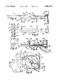
- FIG. 1A illustrates a connector unit or connector 10 that includes a body 15 with a contact body portion 11 and a switch body portion 12.
- the contact body portion 11 holds two rows 17, 19 of contacts 21 that each has a contact blade 20 that is elongated in forward and rearward directions F, R.
- the body has an upper surface or face 24 along which a microcircuit card moves, the body upper surface including continuous, coplanar surface portions 24A, 24B on the two body portions.
- the contact blades 20 project above the surface to engage contact pads 25 (FIG. 2) at the lower surface of the card C.
- the switch body portion 12 (FIG. 1A) holds a switch assembly or switch 47 with a switch actuator 46 that detects the leading edge of a card that is inserted in an insertion direction I which is parallel to the forward direction F.
- a read/write device D that includes the connector 10 commonly has circuitry that passes signals through the contact blades 20 and through contact pads on the microcircuit card, only when the card is in its fully inserted position. The card is detected as lying in its fully inserted position by the switch assembly 47. It is important that the position of the switch actuator 46 be accurately fixed with respect to the contact blades 20.
- FIG. 1A shows a very narrow card CA, with a forward edge 64A, the card being shown only partially installed.
- FIG. 9 shows a more common full size microcircuit card C with its forward edge 64 shown fully inserted, and also shows the connector 10. The small size of the connector 10 with respect to the full size card C can be readily appreciated from the figure.
- the connector 10 of FIG. 1A is designed to be mounted on a printed circuit board of the device D, the device D having slot walls (not shown) that guide opposite sides of the card during its insertion into the device.
- the body 15 includes a base 14 and a cover 16 that lies over the base, both being formed of molded plastic.
- the cover 16 has a plurality of slots 22 through which the contact blades project The contacts have lower ends forming terminals 28 that enable it to be plugged into a circuit board that has plated holes, to be soldered thereat.
- the contact body portion 11 of the body 15 is of substantially rectangular shape as seen in a plan view, with front and rear ends 31, 33 and with opposite sides 37A, 37B.
- the switch body portion 12 extends from an intersection location 32 at the corner of the contact portion 11 which is at the front 31 and second side 37B thereof, and extends forwardly and laterally (along direction L) beyond the side 37B.
- the offsetting (in the lateral direction L) of the switch body portion 12 from the contact body portion 11, is useful in avoiding cramming of the circuit board. That is, there are already two rows of terminals 28 for the contacts 21. The additional pair of terminals 35 for the switch conductors are spaced further from the terminals 28, to provide more room on the circuit board.
- the connector 10 is constructed for surface mounting, wherein surface-mount terminals 28A are provided for the contacts and additional terminals 35A are provided for the switch conductors.
- the terminal ends lie slightly below the bottoms 26 of the body portions.
- the body 15 is formed to accommodate either of these forms of terminals.
- the body has recesses or cutouts 41 at its periphery to surround the surface mount portions of the terminals 28A to protect them from harm, while still providing an opening from the top of the connector.
- the opening formed by cutouts 41 enable soldering to circuit board traces by downwardly-directed infrared heat or by downwardly-moving soldering iron tips that pass down along the cutouts 41.
- the switch actuator 46 (FIG. 1A) lies close to a first side 37B of the switch body portion 12. This assures that the actuator 46 will detect very narrow cards such as shown at CA, whose width would not extend laterally much beyond the switch 46. Most microcircuit cards have a much greater width.
- the lower face 22 of the cover 16 of the housing has studs 31 for relative positioning of the cover 16 to the base 14.
- the switch portion 12 of the body has a cylindrical wall 39 for holding a snap dome-type switch element.
- the switch includes a monostable switch element or snap dome 36.
- the actuator 46 for operating the switch is a sheet metal, resiliently deflectable metal blade.
- a first end 48 of the actuator is fixed to insulation of the body switch portion 12, and is preferably embedded therein.
- a curved connection region 49 connects the fixed end 48 to a main part 50 that includes a circular depressed region or bearing location 52 that lies over the center of the dome element 36.
- An actuator region 68 is bent to lie substantially in a horizontal plane and bears against a surface 69 on the switch body portion 12 to accurately position that actuator region.
- a ramp 54 extends at an upward-forward incline (angle A of over 20°) therefrom, through an opening 56, to a peak 66, the actuator having a turned-down part 58 at its front end. It can be seen from FIG. 5 that the bearing location 52 which directly presses against the dome, lies along a short separate arm 40. This allows the location 52 to suddenly move up or down as the dome snaps, with reduced resistance from the rest of the actuator.
- the actuator pivots largely by bending at the location 49.
- the switch body portion 12 forms an upstanding part 60 (FIG. 6) that projects above the body upper face 24, and that forms a limit stop surface 62 that limits forward movement of a card.
- the ramp 54 bends partially around the location 68, which decreases the force required by the card to depress the peak 66 to close the switch. Bending at 68 also permits the peak 66 to be depressed further than that required for snapping down of the middle of the dome 36, to thereby enable effective operation despite tolerances in manufacture. This also minimizes any tendency for the switch actuator to lift the card.
- the use of a snap dome to make electrical contact minimizes upward force against the inserted card (after the dome snaps), and the actuator construction further minimizes such upward force.
- FIG. 1B shows that the main portion 50 of the actuator has two arms 40, 43 with a slot 45 between them.
- This construction allows the bearing location 52 to suddenly move down or up as the dome snaps down or unsnaps up.
- the use of a snap dome results in a "click" being heard and felt when the card becomes fully inserted, which is desirable.
- FIGS. 10-12 illustrate a modified connector 10A with a single molded base 14A of small thickness.
- the switch actuator 46A projects up through a slot 56A.
- the switch is of the normally open type, and the actuator 46 is of the same construction as shown in FIGS. 1-9.
- the switch is of the normally closed type, so operation of the actuator 46A to depress its front end, allows the middle of a snap dome to move up so the dome unsnaps.
- a variety of switches besides snap-dome types can be used.
- a monostable dome can be inverted so the actuator 46 of FIGS. 1-9 and 12 can be used for a normally closed switch.
- two switches can be used, one normally open and the other normally closed.
- FIGS. 13-15 illustrate a connector switch portion 80 which is similar to that of FIGS. 1-9, except that the switch assembly 82 (FIG. 14) includes an actuator 84 with two elements 86, 88.
- the first or rear element 86 has a fixed end 48A, a curved connection region 49A, and a main part 50A.
- the main part includes a bearing location 52A that lies over the center of a dome element 36A.
- the main part 50A is biased down so it normally keeps the dome in its snapped position to provide a normally closed switch. In the snapped dome position, the center of the dome engages a switch terminal 90 (FIG. 15) to close the switch.
- the second or forward actuator element 88 (FIG. 14) has a pair of trunnions 92 that pivotally mount it on the switch body portion 12A.
- the forward actuator element has a slot 94.
- the rear actuator element has a front end 96 that lies in the slot and that presses down against a slot wall 98. This keeps a ramp portion 100 of the forward actuator element at the position shown in FIG. 15, wherein it projects above the surface 24A to be depressed by the forward edge of the card C. When the ramp 100 is depressed, i lifts the front end 96 of the rear actuator element 86 to lift the bearing location 52A and allow the switch to open.
- the main portion 50A of the rear actuator element has two arms 102, 104 with a slit between them, to allow the dome to rapidly unsnap and snap. It is noted that in FIG. 15, the terminal solderable end 35C is raised to enable at least partial insertion of the body 12A in a circuit board hole.
- FIGS. 16-19 show a connector 110 that does not have an integral switch, and which has surface mount terminals 28B. Otherwise, the connector is the same as the connector portion of FIG. 1A.
- FIG. 20 shows a modified connector 120 with a connector upper portion 122 lying closely in a hole 124 in a circuit board B, while an upwardly-facing shoulder 126 lies against the board lower surface 116.
- the terminals 28D are soldered to traces on the lower surface 116 of the board.
- the terminals or solderable ends 28D lie largely in recesses 41B.
- the invention provides a connector for use with a microcircuit card of the type that has contact pads on the card lower face, where the connector has pad-engaging contacts that carry signals only when the card is in its fully inserted position.
- the connector can integrate a contact body portion that holds the contacts that directly engage the contact pads of the card, with a switch body portion that holds a switch that is operated only when the card has been fully installed. This assures that the relative positions of the switch actuator and contact blades will be accurately fixed. Also, this can provide a common upper surface along which the card moves, to assure that the two upper surface portions are coplanar.
- the switch body portion is preferably laterally offset from the contacting portion.
- the switch assembly can include an actuator that has a separate arm which operates a snap dome.
Abstract
Description
Claims (7)
Priority Applications (2)
| Application Number | Priority Date | Filing Date | Title |
|---|---|---|---|
| US08/986,857 US5807124A (en) | 1994-06-01 | 1997-12-08 | Card connector with switch |
| US09/130,660 US6071136A (en) | 1994-06-01 | 1998-08-07 | Card connector with switch |
Applications Claiming Priority (8)
| Application Number | Priority Date | Filing Date | Title |
|---|---|---|---|
| FR9406684A FR2720865B1 (en) | 1994-06-01 | 1994-06-01 | Switch for detecting the presence of an electronic memory card in a read-write device. |
| FR9406685A FR2720869B1 (en) | 1994-06-01 | 1994-06-01 | Advanced electrical connector for connecting an electronic memory card. |
| FR9406683A FR2720864B1 (en) | 1994-06-01 | 1994-06-01 | Electrical connector for the connection of an electronic memory card comprising an integrated switch for detecting the presence of a card. |
| PCT/FR1995/000708 WO1995033243A1 (en) | 1994-06-01 | 1995-05-31 | Electric connector for connecting an electronic smart card including a built-in switch for detecting the presence of a card |
| PCT/FR1995/000710 WO1995033245A1 (en) | 1994-06-01 | 1995-05-31 | Electric connector for connecting an electronic smart card |
| PCT/FR1995/000709 WO1995033244A1 (en) | 1994-06-01 | 1995-05-31 | Switch for detecting the presence of an electronic memory card in a read/write device |
| US08/588,536 US5775937A (en) | 1994-06-01 | 1996-01-18 | Card connector with switch |
| US08/986,857 US5807124A (en) | 1994-06-01 | 1997-12-08 | Card connector with switch |
Related Parent Applications (1)
| Application Number | Title | Priority Date | Filing Date |
|---|---|---|---|
| US08/588,536 Continuation US5775937A (en) | 1994-06-01 | 1996-01-18 | Card connector with switch |
Related Child Applications (1)
| Application Number | Title | Priority Date | Filing Date |
|---|---|---|---|
| US09/130,660 Continuation US6071136A (en) | 1994-06-01 | 1998-08-07 | Card connector with switch |
Publications (1)
| Publication Number | Publication Date |
|---|---|
| US5807124A true US5807124A (en) | 1998-09-15 |
Family
ID=32475545
Family Applications (3)
| Application Number | Title | Priority Date | Filing Date |
|---|---|---|---|
| US08/588,536 Expired - Lifetime US5775937A (en) | 1994-06-01 | 1996-01-18 | Card connector with switch |
| US08/986,857 Expired - Lifetime US5807124A (en) | 1994-06-01 | 1997-12-08 | Card connector with switch |
| US09/130,660 Expired - Lifetime US6071136A (en) | 1994-06-01 | 1998-08-07 | Card connector with switch |
Family Applications Before (1)
| Application Number | Title | Priority Date | Filing Date |
|---|---|---|---|
| US08/588,536 Expired - Lifetime US5775937A (en) | 1994-06-01 | 1996-01-18 | Card connector with switch |
Family Applications After (1)
| Application Number | Title | Priority Date | Filing Date |
|---|---|---|---|
| US09/130,660 Expired - Lifetime US6071136A (en) | 1994-06-01 | 1998-08-07 | Card connector with switch |
Country Status (1)
| Country | Link |
|---|---|
| US (3) | US5775937A (en) |
Cited By (17)
| Publication number | Priority date | Publication date | Assignee | Title |
|---|---|---|---|---|
| US6066815A (en) * | 1998-08-24 | 2000-05-23 | Illinois Tool Works Inc. | Electrical connector-power switch module |
| US6071136A (en) * | 1994-06-01 | 2000-06-06 | Itt Manufacturing Enterprises, Inc. | Card connector with switch |
| US6086426A (en) * | 1998-03-03 | 2000-07-11 | Hon Hai Precision Ind. Co., Ltd. | Electrical connector |
| US6130387A (en) * | 1997-12-26 | 2000-10-10 | Itt Manufacturing Enterprises, Inc. | Card detecting switch |
| FR2793353A1 (en) * | 1999-05-07 | 2000-11-10 | Itt Mfg Enterprises Inc | MONOBLOCK ELECTRICAL CONNECTOR FOR THE CONNECTION OF AN INTEGRATED CIRCUIT (S) CARD |
| US6159051A (en) * | 1998-06-02 | 2000-12-12 | Hon Hai Precoision Ind. Co., Ltd. | Low profile smart card system |
| US6169257B1 (en) * | 1997-12-24 | 2001-01-02 | Itt Manufacturing Enterprises, Inc. | Smart card actuated dome contact switch |
| US6231394B1 (en) * | 1998-07-02 | 2001-05-15 | Amphenol-Tuchel Electronics Gmbh | Contacts carrier |
| US6264510B1 (en) * | 1997-05-28 | 2001-07-24 | Harness System Technologies Research Ltd. | Laser-welded bus bar structure |
| US6326568B2 (en) | 1997-07-02 | 2001-12-04 | Molex Incorporated | Blade switch assembly for a card reader |
| US6492603B1 (en) | 2001-08-14 | 2002-12-10 | Illinois Tool Works Inc. | Power switch module |
| US6508673B2 (en) | 2000-04-05 | 2003-01-21 | Mcdowell Jennifer Lyn | Low cost smart card reader, extension style, with wiping contacts |
| US6860766B2 (en) | 2002-03-08 | 2005-03-01 | Cinch Connectors, Inc. | Electrical connector |
| US20050132234A1 (en) * | 2002-08-20 | 2005-06-16 | Dawson Thomas P. | Authentication of mobile wireless network component |
| DE102012005852A1 (en) * | 2012-03-22 | 2013-09-26 | Amphenol-Tuchel Electronics Gmbh | Switching spring assembly |
| DE202016102390U1 (en) | 2016-05-04 | 2016-05-23 | Amphenol-Tuchel Electronics Gmbh | Switching spring assembly |
| WO2017191060A1 (en) | 2016-05-04 | 2017-11-09 | Amphenol-Tuchel Electronics Gmbh | Switch spring arrangement |
Families Citing this family (14)
| Publication number | Priority date | Publication date | Assignee | Title |
|---|---|---|---|---|
| FR2752075B1 (en) * | 1996-08-01 | 1998-12-18 | Framatome Connectors Int | FLAT SUPPORT DETECTOR AND CONNECTOR COMPRISING SUCH A DETECTOR |
| US5907197A (en) * | 1997-06-30 | 1999-05-25 | Compaq Computer Corporation | AC/DC portable power connecting architecture |
| JP3288277B2 (en) * | 1997-09-16 | 2002-06-04 | アルプス電気株式会社 | IC card connector |
| US6027365A (en) * | 1998-05-28 | 2000-02-22 | The Whitaker Corporation | Test card receptacle and header |
| JP2001015194A (en) | 1999-05-05 | 2001-01-19 | Thomas & Betts Corp <T&B> | Improved smart card reader used at dispositions elevated from printed circuit board |
| FR2793921B1 (en) | 1999-05-17 | 2001-06-29 | Itt Mfg Enterprises Inc | COMPACT ASSEMBLY FOR CONNECTING A CARD WITH AN INTEGRATED CIRCUIT (S) COMPRISING MEANS OF EJECTING THE CARD |
| US6296500B1 (en) * | 2000-04-13 | 2001-10-02 | Hon Hai Precision Ind. Co., Ltd. | Electrical card connector having a switch device |
| JP3961224B2 (en) | 2001-02-26 | 2007-08-22 | アルプス電気株式会社 | Card connector device |
| US6642460B2 (en) | 2002-01-23 | 2003-11-04 | Eaton Corporation | Switch assembly employing an external customizing printed circuit board |
| KR101327302B1 (en) * | 2012-04-30 | 2013-11-20 | 한국몰렉스 주식회사 | Dual memory card socket and manufacturing method thereof |
| WO2015167833A1 (en) * | 2014-04-30 | 2015-11-05 | Thomson Licensing | Information card socket assembly |
| USD719159S1 (en) * | 2014-06-17 | 2014-12-09 | Square, Inc. | Card reader stabilizer |
| US9224018B1 (en) | 2014-08-20 | 2015-12-29 | Square, Inc. | Swipe-guide for card reader |
| DE102018203970A1 (en) * | 2018-03-15 | 2019-09-19 | Zf Friedrichshafen Ag | Bridge element for producing an electrical connection and arrangement |
Citations (9)
| Publication number | Priority date | Publication date | Assignee | Title |
|---|---|---|---|---|
| US3638033A (en) * | 1970-05-11 | 1972-01-25 | Sylvania Electric Prod | Display device and electrical conductors therefor |
| EP0274288A1 (en) * | 1986-11-21 | 1988-07-13 | Schlumberger Industries | Connection unit for electronic memory cards, and reading/writing device using the same |
| EP0274534A1 (en) * | 1986-06-24 | 1988-07-20 | Hosiden Electronics Co., Ltd. | Connector |
| EP0316699A1 (en) * | 1987-11-13 | 1989-05-24 | Connectors Pontarlier | Contact frame for an IC card reader having a terminating contact |
| EP0366513A1 (en) * | 1988-10-26 | 1990-05-02 | Itt Composants Et Instruments | Electrical connector for electronic memory cards, process for producing such a connector and read-write device incorporating such a connector |
| FR2658364A1 (en) * | 1990-02-15 | 1991-08-16 | Itt Composants Instr | Electrical connector for electronic-memory cards |
| EP0474519A1 (en) * | 1990-07-23 | 1992-03-11 | Itt Composants Et Instruments | Connector for electric memory cards |
| EP0568971A1 (en) * | 1992-05-08 | 1993-11-10 | Molex Incorporated | Electrical connector with contact anti-overstress means |
| EP0587497A1 (en) * | 1992-09-09 | 1994-03-16 | Framatome Connectors International | Electrical connector for a microcircuit card |
Family Cites Families (4)
| Publication number | Priority date | Publication date | Assignee | Title |
|---|---|---|---|---|
| FR2640780A1 (en) * | 1988-12-20 | 1990-06-22 | Cit Alcatel | CHIP CARD READER |
| FR2717626B1 (en) * | 1994-03-21 | 1996-04-19 | Pontarlier Connectors | Case for microcircuit card reader. |
| FR2717625B1 (en) * | 1994-03-21 | 1996-06-28 | Pontarlier Connectors | Case for microcircuit card reader. |
| US5775937A (en) * | 1994-06-01 | 1998-07-07 | Itt Composants Et Instrumets | Card connector with switch |
-
1996
- 1996-01-18 US US08/588,536 patent/US5775937A/en not_active Expired - Lifetime
-
1997
- 1997-12-08 US US08/986,857 patent/US5807124A/en not_active Expired - Lifetime
-
1998
- 1998-08-07 US US09/130,660 patent/US6071136A/en not_active Expired - Lifetime
Patent Citations (9)
| Publication number | Priority date | Publication date | Assignee | Title |
|---|---|---|---|---|
| US3638033A (en) * | 1970-05-11 | 1972-01-25 | Sylvania Electric Prod | Display device and electrical conductors therefor |
| EP0274534A1 (en) * | 1986-06-24 | 1988-07-20 | Hosiden Electronics Co., Ltd. | Connector |
| EP0274288A1 (en) * | 1986-11-21 | 1988-07-13 | Schlumberger Industries | Connection unit for electronic memory cards, and reading/writing device using the same |
| EP0316699A1 (en) * | 1987-11-13 | 1989-05-24 | Connectors Pontarlier | Contact frame for an IC card reader having a terminating contact |
| EP0366513A1 (en) * | 1988-10-26 | 1990-05-02 | Itt Composants Et Instruments | Electrical connector for electronic memory cards, process for producing such a connector and read-write device incorporating such a connector |
| FR2658364A1 (en) * | 1990-02-15 | 1991-08-16 | Itt Composants Instr | Electrical connector for electronic-memory cards |
| EP0474519A1 (en) * | 1990-07-23 | 1992-03-11 | Itt Composants Et Instruments | Connector for electric memory cards |
| EP0568971A1 (en) * | 1992-05-08 | 1993-11-10 | Molex Incorporated | Electrical connector with contact anti-overstress means |
| EP0587497A1 (en) * | 1992-09-09 | 1994-03-16 | Framatome Connectors International | Electrical connector for a microcircuit card |
Cited By (26)
| Publication number | Priority date | Publication date | Assignee | Title |
|---|---|---|---|---|
| US6071136A (en) * | 1994-06-01 | 2000-06-06 | Itt Manufacturing Enterprises, Inc. | Card connector with switch |
| US6793543B2 (en) | 1997-05-28 | 2004-09-21 | Autonetworks Technologies, Ltd. | Bus bar structure |
| US6761598B2 (en) | 1997-05-28 | 2004-07-13 | Autonetworks Technologies, Ltd. | Bus bar structure |
| US6264510B1 (en) * | 1997-05-28 | 2001-07-24 | Harness System Technologies Research Ltd. | Laser-welded bus bar structure |
| US6326568B2 (en) | 1997-07-02 | 2001-12-04 | Molex Incorporated | Blade switch assembly for a card reader |
| US6169257B1 (en) * | 1997-12-24 | 2001-01-02 | Itt Manufacturing Enterprises, Inc. | Smart card actuated dome contact switch |
| US6130387A (en) * | 1997-12-26 | 2000-10-10 | Itt Manufacturing Enterprises, Inc. | Card detecting switch |
| US6086426A (en) * | 1998-03-03 | 2000-07-11 | Hon Hai Precision Ind. Co., Ltd. | Electrical connector |
| US6159051A (en) * | 1998-06-02 | 2000-12-12 | Hon Hai Precoision Ind. Co., Ltd. | Low profile smart card system |
| US6231394B1 (en) * | 1998-07-02 | 2001-05-15 | Amphenol-Tuchel Electronics Gmbh | Contacts carrier |
| US6066815A (en) * | 1998-08-24 | 2000-05-23 | Illinois Tool Works Inc. | Electrical connector-power switch module |
| WO2000068867A1 (en) * | 1999-05-07 | 2000-11-16 | Itt Manufacturing Enterprises Inc. | One-piece electrical connector for the connection of a smart card |
| FR2793353A1 (en) * | 1999-05-07 | 2000-11-10 | Itt Mfg Enterprises Inc | MONOBLOCK ELECTRICAL CONNECTOR FOR THE CONNECTION OF AN INTEGRATED CIRCUIT (S) CARD |
| US6508673B2 (en) | 2000-04-05 | 2003-01-21 | Mcdowell Jennifer Lyn | Low cost smart card reader, extension style, with wiping contacts |
| US6492603B1 (en) | 2001-08-14 | 2002-12-10 | Illinois Tool Works Inc. | Power switch module |
| US6860766B2 (en) | 2002-03-08 | 2005-03-01 | Cinch Connectors, Inc. | Electrical connector |
| US20050132234A1 (en) * | 2002-08-20 | 2005-06-16 | Dawson Thomas P. | Authentication of mobile wireless network component |
| US7356691B2 (en) | 2002-08-20 | 2008-04-08 | Sony Corporation | Authentication of mobile wireless network component |
| DE102012005852A1 (en) * | 2012-03-22 | 2013-09-26 | Amphenol-Tuchel Electronics Gmbh | Switching spring assembly |
| DE102012005852B4 (en) * | 2012-03-22 | 2014-02-27 | Amphenol-Tuchel Electronics Gmbh | Switching spring assembly |
| US9589750B2 (en) | 2012-03-22 | 2017-03-07 | Amphenol-Tuchel Electronics Gmbh | Switch spring arrangement |
| DE202016102390U1 (en) | 2016-05-04 | 2016-05-23 | Amphenol-Tuchel Electronics Gmbh | Switching spring assembly |
| WO2017191060A1 (en) | 2016-05-04 | 2017-11-09 | Amphenol-Tuchel Electronics Gmbh | Switch spring arrangement |
| DE102016108319A1 (en) | 2016-05-04 | 2017-11-09 | Amphenol-Tuchel Electronics Gmbh | Switching spring assembly |
| DE102016108319B4 (en) | 2016-05-04 | 2018-08-02 | Amphenol-Tuchel Electronics Gmbh | Switching spring assembly |
| US10438028B2 (en) | 2016-05-04 | 2019-10-08 | Amphenol-Tuchel Electronics Gmbh | Switch spring arrangement |
Also Published As
| Publication number | Publication date |
|---|---|
| US5775937A (en) | 1998-07-07 |
| US6071136A (en) | 2000-06-06 |
Similar Documents
| Publication | Publication Date | Title |
|---|---|---|
| US5807124A (en) | Card connector with switch | |
| US6120328A (en) | Thin smart card connector | |
| US10135199B1 (en) | Electrical connector | |
| US6358074B2 (en) | Card detecting connector | |
| US6851968B2 (en) | Electrical connector for flat type conductor | |
| US6398598B2 (en) | Electrical connector | |
| US6305960B1 (en) | SIM card connector with improved detecting switch | |
| US6561819B1 (en) | Terminals of socket connector | |
| EP0889493B1 (en) | Electrical switch assembly | |
| US6786748B2 (en) | Switch in smart card connector | |
| JP3216050B2 (en) | Low profile surface mount electrical connector | |
| US6576853B2 (en) | Switch exhibition non-unidirectional displacement | |
| US6368156B1 (en) | Audio jack conveniently and reliably mounted on a circuit board | |
| JP2000506638A (en) | Smart card and smart card connector | |
| US6478630B1 (en) | Electrical card connector having polarization mechanism | |
| US6130387A (en) | Card detecting switch | |
| US6325655B1 (en) | Electrical connector for a PGA package | |
| US6540526B2 (en) | Electrical connector | |
| EP1349240B1 (en) | Connector in which movement of contact portion of contact is guided by insulator | |
| US7775821B2 (en) | Socket for burn-in tests | |
| US7973256B2 (en) | Spring-biased switch for an electronic device | |
| JPH11250194A (en) | Ic card reader | |
| US6120310A (en) | Switch device for electrical card connector | |
| US6169257B1 (en) | Smart card actuated dome contact switch | |
| GB2028591A (en) | Sliding electrical switch |
Legal Events
| Date | Code | Title | Description |
|---|---|---|---|
| STCF | Information on status: patent grant |
Free format text: PATENTED CASE |
|
| CC | Certificate of correction | ||
| FEPP | Fee payment procedure |
Free format text: PAYOR NUMBER ASSIGNED (ORIGINAL EVENT CODE: ASPN); ENTITY STATUS OF PATENT OWNER: LARGE ENTITY |
|
| FPAY | Fee payment |
Year of fee payment: 4 |
|
| REMI | Maintenance fee reminder mailed | ||
| FPAY | Fee payment |
Year of fee payment: 8 |
|
| AS | Assignment |
Owner name: CREDIT SUISSE, NEW YORK Free format text: FIRST LIEN INTELLECTUAL PROPERTY SECURITY AGREEMENT;ASSIGNORS:DELTATECH CONTROLS, INC.;LJ SWITCH HOLDINGS 1, LLC;LJ SWITCH HOLDINGS 2, LLC;AND OTHERS;REEL/FRAME:019725/0073 Effective date: 20070726 Owner name: CREDIT SUISSE, NEW YORK Free format text: SECOND LIEN INTELLECTUAL PROPERTY SECURITY AGREEMENT;ASSIGNORS:DELTATECH CONTROLS, INC.;LJ SWITCH HOLDINGS 1, LLC;LJ SWITCH HOLDINGS 2, LLC;AND OTHERS;REEL/FRAME:019725/0153 Effective date: 20070726 Owner name: CREDIT SUISSE,NEW YORK Free format text: FIRST LIEN INTELLECTUAL PROPERTY SECURITY AGREEMENT;ASSIGNORS:DELTATECH CONTROLS, INC.;LJ SWITCH HOLDINGS 1, LLC;LJ SWITCH HOLDINGS 2, LLC;AND OTHERS;REEL/FRAME:019725/0073 Effective date: 20070726 Owner name: CREDIT SUISSE,NEW YORK Free format text: SECOND LIEN INTELLECTUAL PROPERTY SECURITY AGREEMENT;ASSIGNORS:DELTATECH CONTROLS, INC.;LJ SWITCH HOLDINGS 1, LLC;LJ SWITCH HOLDINGS 2, LLC;AND OTHERS;REEL/FRAME:019725/0153 Effective date: 20070726 |
|
| AS | Assignment |
Owner name: ITT INDUSTRIES, FRANCE Free format text: CHANGE OF NAME;ASSIGNOR:ITT COMPOSANTS ET INSTRUMENTS;REEL/FRAME:020339/0618 Effective date: 20000701 Owner name: C & K COMPONENTS SAS, FRANCE Free format text: CHANGE OF NAME;ASSIGNOR:ITT INDUSTRIES;REEL/FRAME:020339/0646 Effective date: 20070726 |
|
| FPAY | Fee payment |
Year of fee payment: 12 |
|
| AS | Assignment |
Owner name: COACTIVE TECHNOLOGIES, LLC (F/K/A DELTATECH CONTRO Free format text: RELEASE OF SECURITY INTEREST;ASSIGNOR:CREDIT SUISSE AG, CAYMAN ISLANDS BRANCH (F/K/A CREDIT SUISSE);REEL/FRAME:033645/0324 Effective date: 20140804 Owner name: LJ SWITCH US HOLDINGS, INC., CONNECTICUT Free format text: RELEASE OF SECURITY INTEREST;ASSIGNOR:CREDIT SUISSE AG, CAYMAN ISLANDS BRANCH (F/K/A CREDIT SUISSE);REEL/FRAME:033645/0324 Effective date: 20140804 Owner name: DELTATECH CONTROLS USA, LLC (F/K/A/ LJ SWITCH SHAK Free format text: RELEASE OF SECURITY INTEREST;ASSIGNOR:CREDIT SUISSE AG, CAYMAN ISLANDS BRANCH (F/K/A CREDIT SUISSE);REEL/FRAME:033645/0324 Effective date: 20140804 Owner name: MMI SANTA ANA, LLC (F/K/A LJ SWITCH SANTA ANA, LLC Free format text: RELEASE OF SECURITY INTEREST;ASSIGNOR:CREDIT SUISSE AG, CAYMAN ISLANDS BRANCH (F/K/A CREDIT SUISSE);REEL/FRAME:033645/0324 Effective date: 20140804 Owner name: C&K COMPONENTS, INC., MASSACHUSETTS Free format text: RELEASE OF SECURITY INTEREST;ASSIGNOR:CREDIT SUISSE AG, CAYMAN ISLANDS BRANCH (F/K/A CREDIT SUISSE);REEL/FRAME:033645/0324 Effective date: 20140804 Owner name: LJ SWITCH US, LLC, CONNECTICUT Free format text: RELEASE OF SECURITY INTEREST;ASSIGNOR:CREDIT SUISSE AG, CAYMAN ISLANDS BRANCH (F/K/A CREDIT SUISSE);REEL/FRAME:033645/0324 Effective date: 20140804 Owner name: LJ SWITCH HOLDINGS 2, LLC, CONNECTICUT Free format text: RELEASE OF SECURITY INTEREST;ASSIGNOR:CREDIT SUISSE AG, CAYMAN ISLANDS BRANCH (F/K/A CREDIT SUISSE);REEL/FRAME:033645/0324 Effective date: 20140804 Owner name: LJ SWITCH HOLDINGS 1, LLC, DELAWARE Free format text: RELEASE OF SECURITY INTEREST;ASSIGNOR:CREDIT SUISSE AG, CAYMAN ISLANDS BRANCH (F/K/A CREDIT SUISSE);REEL/FRAME:033645/0324 Effective date: 20140804 |