US5811776A - Method and apparatus for accurately locating data regions in stored images of symbols - Google Patents
Method and apparatus for accurately locating data regions in stored images of symbols Download PDFInfo
- Publication number
- US5811776A US5811776A US08/607,100 US60710096A US5811776A US 5811776 A US5811776 A US 5811776A US 60710096 A US60710096 A US 60710096A US 5811776 A US5811776 A US 5811776A
- Authority
- US
- United States
- Prior art keywords
- vertical reference
- points
- symbol
- outermost
- point
- Prior art date
- Legal status (The legal status is an assumption and is not a legal conclusion. Google has not performed a legal analysis and makes no representation as to the accuracy of the status listed.)
- Expired - Lifetime
Links
Images


Classifications
-
- G—PHYSICS
- G06—COMPUTING; CALCULATING OR COUNTING
- G06K—GRAPHICAL DATA READING; PRESENTATION OF DATA; RECORD CARRIERS; HANDLING RECORD CARRIERS
- G06K7/00—Methods or arrangements for sensing record carriers, e.g. for reading patterns
- G06K7/10—Methods or arrangements for sensing record carriers, e.g. for reading patterns by electromagnetic radiation, e.g. optical sensing; by corpuscular radiation
- G06K7/14—Methods or arrangements for sensing record carriers, e.g. for reading patterns by electromagnetic radiation, e.g. optical sensing; by corpuscular radiation using light without selection of wavelength, e.g. sensing reflected white light
- G06K7/1404—Methods for optical code recognition
- G06K7/1439—Methods for optical code recognition including a method step for retrieval of the optical code
- G06K7/1443—Methods for optical code recognition including a method step for retrieval of the optical code locating of the code in an image
-
- G—PHYSICS
- G06—COMPUTING; CALCULATING OR COUNTING
- G06K—GRAPHICAL DATA READING; PRESENTATION OF DATA; RECORD CARRIERS; HANDLING RECORD CARRIERS
- G06K7/00—Methods or arrangements for sensing record carriers, e.g. for reading patterns
- G06K7/10—Methods or arrangements for sensing record carriers, e.g. for reading patterns by electromagnetic radiation, e.g. optical sensing; by corpuscular radiation
- G06K7/14—Methods or arrangements for sensing record carriers, e.g. for reading patterns by electromagnetic radiation, e.g. optical sensing; by corpuscular radiation using light without selection of wavelength, e.g. sensing reflected white light
Definitions
- the present invention relates to determining the location of data regions of a symbol in a stored image, and more particularly, to methods and apparatus for identifying the areas of a two-dimensional matrix symbol where data are encoded in a stored image for processing and decoding by a symbology reader.
- Machine readable symbologies are widely used for data collection.
- the first bar code symbologies developed, such as UPC, EAN, Code 39 and Code 93 can be referred to as "linear" symbologies because the data in a given symbol was decoded along one direction or axis.
- the next generation of bar code symbologies, called stacked reader symbologies, such as Code 49 and PDF 417, increase the information density of the symbol by employing several adjacent rows, each row having several symbol characters defined by groups of multiple width bars and spaces.
- Code One is a two-dimensional matrix symbology.
- Code One symbols include a recognition pattern 802, a matrix of square data cells 804 (rather than one or more rows of bars and spaces), and vertical reference patterns 806 that extend away from the recognition pattern 802.
- the areas of square data cells 804 above the recognition pattern 802, and below the recognition pattern 802, respectively, are defined by an upper bounding box 808 and a lower bounding box 809.
- the recognition pattern 802 runs horizontally through the Code One symbol 800, while the vertical reference patterns 806 extend perpendicularly from the recognition pattern 802. These vertical recognition patterns 806 are used to help find the symbol, and determine the symbol's tilt and orientation to take into account any surface curvature.
- Each of the data cells 804 in the matrix encodes one bit of data: a white data cell represents a 0 and a black data cell represents a 1.
- Each symbol character in the Code One symbology is generally constructed from eight data cells in a rectangular array 807 of two rows that each have four data cells. Each set of eight data cells in a Code One symbol character encodes an 8-bit byte of binary data.
- the ASCII values in the Code One symbology are equal to the standard ASCII values in the computer industry plus one.
- each row of symbol characters in a Code One symbol consists of a pair of adjacent rows of data cells.
- the first symbol character in the Code One symbol is in the top left corner of the symbol and the last symbol character is in the bottom right corner.
- a reader analyzes the symbol characters in a Code One symbol from the first symbol character in the symbol's top left corner rightward to the right edge of the top row, and then from the left edge rightward along the second row, and so forth (assuming the symbol is oriented as shown in FIG. 1). If the reader encounters no difficulties, then each symbol character analyzed in a Code One or other symbology is converted into corresponding data to be used by the reader, the user, or other peripheral equipment.
- the recognition pattern 802 is comprised of a plurality of elements including bars 810 and spaces 812.
- the recognition pattern 802 is used to identify the version (i.e., the type) of Code One symbol being used. Further, the recognition pattern 802 is used to determine the X-dimension of the Code One symbol 800. For example, the X-dimension represents the smallest height (or width) of the data cells 804 in the Code One symbology. The X-dimension is used to determine the intended dimension that an area symbology is based on, regardless of printing errors, and is necessary for decoding the symbology.
- the reader typically used to scan the Code One symbol 800 is a two-dimensional imaging device which detects all the spaces 810 and the bars 812 of the recognition pattern 802, as well as the vertical reference patterns 806 using a fast linear image search routine used in high-speed scanning applications.
- a memory stores the scanned image and includes an array of memory locations that correspond to and represent a pixel field of view of the reader (e.g., a rectangular array of 582 by 752 pixels).
- the stored image is referenced by a Cartesian coordinate system relative to the imaging device or memory so that the location of each pixel is represented by a pair of numbers indicating the horizontal and vertical position of the pixel in the stored image.
- the first pixel in the top left corner of the stored image is assigned the Cartesian coordinates (0,0) while the bottom right-most pixel is assigned the coordinates (752,582). Therefore, data cells 804 associated with groups of pixels can be arithmetically located using known geometric and trigonometric properties based on the coordinate system.
- the image search routine was used to locate a long bar 814 of the recognition pattern 802, then the X-dimension was determined from the recognition pattern 802. Next, an angle 816 that the long bar 814 makes with the X axis of the Cartesian coordinate system of the overall image was determined. Finally, using the X-dimension and angle 816, a bounding box 807 of the symbol 800 defined by the boundary lines of the symbol 800 was determined.
- the prior method computes one bounding box 807 for the Code One symbol 800 enclosing the entire symbol 800.
- the boundary box 807 is the sum of upper bounding box 808, lower bounding box 809 and the center pattern recognition 802.
- an end point 818 of the long bar 814 i.e., ep 1
- a path 820 substantially along the Y-axis of the Cartesian coordinate system, i.e., directed away from the recognition pattern 802, was traversed for a predetermined number of the X-dimensions.
- the direction of the path 820 was determined by the angle that is vertical to the long bar 814 (i.e., the angle 816) to establish an end corner point cp 1 824 of the bounding box 807.
- the other corner point 828, i e., cp 2 , of the bounding box 807, and the other corner points 842 and 844, i.e., cp 3 and cp 4 , of the bounding box 807 were determined in a similar manner. With these corner points, the complete bounding box 807 was defined, and all square data cells 804 were assumed to lie within this region for purposes of information retrieval from the image when the size of the X-dimension and the version of the symbol were known.
- the prior art method of determining the bounding box 807 of the Code One symbol is effective when the symbol 800 is in its proper position, and has no significant surface curvature, it becomes highly prone to errors when the symbology 800 is optically distorted, e.g., when an image of the symbol is stored when a reader is significantly tilted with respect to the symbol.
- the upper and lower bounding boxes 808 and 809 do not have the same size and shape, and the X-dimension varies within the symbol, data can be lost during the decoding process.
- an optically distorted symbol 801 in FIG. 3 even a slight deviation between the angle the long bar 814 makes with an X axis of the Cartesian coordinate system causes the computed bounding box 807 defined by the dashed boundaries with four corners cp1, cp2, cp3, and cp4 to differ from the true bounding box for the symbol (shown as the solid line quadrilateral 830).
- optical distortions causing the stored image of the symbol to appear trapezoidal or otherwise optically distorted causes the perimeter of the stored image of the symbol 830 to differ significantly from the bounding box 807 computed by the prior art method. As a result, information retrieval errors will result by sampling within the computed bounding box 807.
- Important data within the true bounding box 830 can be ignored, such as the information located in shaded areas 837 of FIG. 3. This is because when following an angle that has a slight error, the resulting positional error can be huge if the distance along the path is large enough. In other words, the error will accumulate to a significant degree using the prior art method, even if only a small amount of error is present in the direction of the path. Similarly, when there is a slight error in X-dimension, the total error will be larger if the distance is large enough. Thus, what is needed is a method of determining the bounding box that localized the data region and is free from error, and which will ensure that all the square data cells 804 fall within the true bounding box.
- a method and apparatus locates four or more "bounding boxes" within one or more data areas in an image of a symbol located within an image stored by a reader.
- the symbol preferably has a recognition pattern with a longitudinally extending bar and at least two vertically reference bars extending therefrom, such as in the Code One symbology.
- Each vertically extending reference bar includes at least one horizontally extending block (often with one block at the free end of the bar and one or more between the free end and the longitudinally extending bar).
- the method locates the positions of landmark points within the stored image.
- Landmark points include points at the free ends of the longitudinally extending bars, points at the corner or root formed between the longitudinally extending bar and the vertically extending bars, and points at the corners of the blocks and the vertically extending bars.
- lines are projected between collinear landmark points to construct at least four bounding boxes, two above the center recognition pattern and two below it, and thereby determine the boundaries of the data areas of the symbol within the stored image.
- bounding boxes two above the center recognition pattern and two below it
- the present invention embodies a method for computing a location of data regions enclosed by the corresponding bounding boxes in a stored image of a symbol.
- the symbol includes a recognition pattern having an outermost bar and at least one vertical reference pattern extending perpendicularly from the recognition pattern.
- the method includes the steps of: (i) locating a position of first and second end portions of the outermost bar of the recognition pattern; (ii) locating a position of a root portion of an intersection between each vertical reference pattern and the outermost bar; (iii) locating a position of an outermost portion of each vertical reference pattern; (iv) determining a position of first and second corner portions for the symbol by extending at least one line from the outermost portion a predetermined distance in a predetermined direction; and (v) defining at least first and second areas enclosing the data regions of the symbol, the first area being defined by the positions of the first end portion, the first corner portion, the root portion, and the outermost portion, and the second area being defined by the second end portion, the second corner portion, the root portion, and the outermost portion.
- the present invention also embodies an apparatus for decoding a machine-readable symbol that represents encoded information.
- the symbol has a recognition pattern with an outermost bar and at least one vertical reference pattern extending approximately perpendicular from the recognition pattern.
- the apparatus includes a sensor that receives light reflected from the symbol. The sensor produces an output signal therefrom.
- a receiver receives the output signal and produces a data signal indicative of the encoded information, the recognition pattern and at least one vertical reference pattern.
- a processor for decoding the encoded information encoded in the symbol is programmed to (a) locate a position of a first end point and a second end point of the outermost bar of the recognition pattern, (b) locate a root position of each of the vertical reference patterns and an outermost point of each of the at least one vertical reference patterns, (c) determine a position of a first corner point and a second corner point for this symbol by extending at least one line from the outermost point a predetermined distance in a predetermined direction, (d) define a plurality of bounding boxes using the positions of the first and second end points, the first and second corner points, the outermost points, and the positions of the at least one vertical reference patterns, and (e) decode the encoded information within the plurality of bounding boxes.
- the processor is also programmed to similarly determine the periphery of a lower data region of the symbol.
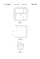
- FIG. 1 shows a Version E Code One symbol.
- FIG. 2 is a schematic diagram of a Code One recognition pattern that shows an example of a conventional method for determining a bounding box of a Code One symbol.
- FIG. 3 is a schematic diagram of an optically distorted image of a version E Code One symbol as stored by an imaging device that is misaligned and tilted with respect to the symbol.
- FIG. 4 shows a block diagram of a symbology reader of the present invention.
- FIG. 5 is a schematic diagram of an area of a Code One symbol of FIG. 4.
- FIG. 6 is a schematic diagram showing the area of FIG. 5 subdivided into several blocks.
- FIG. 7 is a schematic diagram of a block of FIG. 6 further divided by a series of lines for identifying data cells within a block.
- FIG. 8A is a graph of errors in decoding symbols per area.
- FIG. 8B is a schematic diagram, similar to FIG. 3, of an optically distorted image of a version E Code One symbol whose area has been subdivided into a series of blocks under the method of the present invention.
- FIG. 9 is a version A Code One symbol whose data area is enclosed by four bounding boxes.
- FIG. 10 is a version B Code One symbol whose data area is enclosed by four bounding boxes.
- FIG. 11 is a version C Code One symbol whose data area is enclosed by six bounding boxes.
- FIG. 12A is a version D Code One symbol whose data area is enclosed by eight bounding boxes.
- FIG. 12B is a version D Code One symbol whose data area is enclosed by sixteen bounding boxes.
- FIG. 13 is a version E Code One symbol whose data area is enclosed by sixteen bounding boxes.
- FIG. 14 is a version F Code One symbol whose data area is enclosed by thirty bounding boxes.
- FIG. 15A is a schematic diagram of a Code One recognition pattern that shows a method of accurately determining the bounding box of a Code One symbol.
- FIG. 15B is a schematic diagram that shows an example of determining a first corner point cp 1 for an upper data region of the symbol of FIG. 15A.
- FIG. 15C is a schematic diagram that shows an example of determining a second corner point cp 2 of the upper data region of the symbol of FIG. 15A.
- FIG. 16 is a flowchart which shows a main program implementing an exemplary method used to determine the bounding box of a symbol.
- FIG. 17 is a flowchart of a subroutine in the first embodiment used to locate root points between a top long bar and vertical reference bars extending therefrom in the symbol of FIG. 15A.
- FIG. 18 is a flowchart of a subroutine for finding intersection points between all blocks on each vertical reference bar of the symbol of FIG. 15A.
- FIG. 19 is a flowchart of a subroutine for crossing blocks of each vertical reference bar of the symbol of FIG. 15A.
- FIG. 20 is a flowchart of a subroutine for crossing the center recognition pattern and locating lower root points of the symbol of FIGS. 15A.
- FIG. 21 is a flowchart of a subroutine for computing the end points ep' 1 and ep' 2 for a lower edge of the center recognition pattern of the symbol of FIG. 15A.
- FIG. 22 is a flowchart of a subroutine for defining lines for bounding boxes for the symbol of FIG. 15A.
- FIG. 23 is a flowchart of a subroutine to determine corner points of the symbol of FIG. 15, such as a corner point cp 1 .
- a data collection symbology reader 20 of the present invention includes a light source 22 that illuminates a data collection symbol, such as Code One symbol 24 having a recognition pattern 26 and vertical reference patterns 28, as well as square data cells 30.
- a data collection symbol refers to a symbol from any linear, stacked, area or other machine-readable symbology.
- a sensor 32 in the reader 20 receives the light reflected from the symbol 24 and converts the received light into an electrical signal.
- the light source 22 is preferably a flashbulb, infrared light source, one or more LEDs or other light-emitting elements, while the sensor 32 is preferably a charge-coupled device ("CCD"), two-dimensional semi-conductor array, vidicon, or other area imager capable of converting received light into electrical signals.
- CCD charge-coupled device
- a receiver or converter 34 receives the electrical signals from the sensor 32 and converts it into a signal to be processed by a programmed computer or processor 36.
- the sensor 32 produces an analog signal that represents the modulated light reflected from the elements in the symbol 24.
- the processor 20 is a digital computer, then the converter 34 converts the analog signal into a digital signal to be processed by the processor 36.
- the converter 34 and/or processor 36 preferably include a memory for storing the digital signal.
- the processor 36 of the reader 20 performs a routine stored in memory that provides an accurate estimate of bounding boxes 38 of the symbol 24 regardless of whether the symbol 24 is tilted with respect to the reader 20.
- the routine accomplishes this by finding positions on the vertical reference bars 28 as well as top and bottom bars 50 and 107 in the recognition pattern 26 and uses them to determine corner points of the bounding boxes.
- the path traveled to reach the corner points is reduced (i.e., the number of X-dimensions traveled is reduced) and this minimizes any deviation caused by a small error in the X-dimension or in the angle of the recognition pattern 26 with respect to a Cartesian coordinate system used for retrieval of information in the image stored by the reader 20.
- the sensor 32 preferably includes a rectangular array of photosensitive elements such as CCDs.
- Each CCD element in the rectangular array preferably outputs a gray level signal ranging from 1-15, i.e., an analog signal that determines the amount of intensity of light impinging upon a particular pixel element.
- each pixel element in the array of the sensor 32 can output a binary signal indicating that the particular pixel element is either black or white.
- the processor 36 stores the signals produced by the sensor in an image within a field of view of the sensor 32. As a result, the processor 36 may repeatedly analyze and manipulate the stored signals.
- the reader 20 can be a hand-held product and can include a trigger switch 40 coupled to the processor 36.
- the processor 36 By actuating the trigger switch 40, the processor 36 causes the light source 22 to provide light to the symbol 24 that is reflected therefrom to the sensor 32. Since the processor 36 stores the signals that are output from the sensor 32 and converted by the converter 34, a user, by actuating the trigger switch 40, can cause the reader 20 to store an instantaneous image within the field of view of the reader 20, creating a snapshot of the symbol 24.
- the specific means and method for storing and locating an image of the symbol 24 are well known and will be understood by those in the relevant art without further need for description herein.
- the routine stored in the memory of processor 36 uses the instantaneous image stored in the reader 20 to define several bounding boxes for data areas in a data collection symbol, such as the Code One symbol 24.
- a data collection symbol such as the Code One symbol 24.
- the Code One symbol 24 has a total data area A.
- optical distortion particularly when imaging and storing the symbol 24, can cause the data area A to diverge significantly from a substantially square area standard in most Code One symbols.
- it can be particularly difficult for the reader 20 to locate the periphery of the data area A, and therefore difficult to locate the outer boundaries of the data area for the symbol 24.
- the data encoded in area A of the symbol 24 can be represented by a series of sample points within the data area A, as represented by the following equation: ##EQU1## where a i refers to the sample points within the data area A, and where the data area A has an area of M by N.
- the center recognition pattern area and the vertical reference bars do not include encoded data.
- the data area A of the symbol 24 is subdivided into several bounding boxes, shown as boxes C 0 through C K in FIG. 6.
- the data area A as divided into several boxes C, can be represented by the union of the boxes, as in the following equation: ##EQU2##
- K represents the total number of boxes within the data area A
- the total number of sample points within each box C i is represented by the following equation: ##EQU3## where T represents the total number of sample points within a given box.
- the boxes C 0 through C K can then be further subdivided by defining regular points along sides L 1 , L 2 , L 3 , and L 4 of the boxes, spaced apart by a distance equal to the X-dimension. Horizontal and vertical lines can then be drawn connecting opposite points, such as shown in FIG. 7 by exemplary lines l i and l j . At the intersection of each line a sample point or "data cell" should exist.
- the data cells within the symbol 24 should be located within some or all of the boxes C 1 . . . C k , if they have been appropriately defined within the data area A so that the boxes totally fill the data area A without overlap, or without extending beyond the data area A.
- Individual data cells within each box C i can be defined and located by the intersection points of lines l i and l j where i and j are defined as follows:
- N' refers to the number of points on left and right opposing lines L 1 and L 2 that divide these lines into regular intervals (such as the X-dimension), and where N" refers to the number of points on top and bottom opposing lines L 3 and L 4 .
- the graph in FIG. 8A shows why the division of the data area A for the symbol 24 into several smaller boxes C i provides an improved method for locating the data area of a symbol.
- the number of errors due to geometric distortion of the boundary box non-linearly increases with the increase in the data area for a given symbol. For example, assuming that the data area A for the symbol 24 has an area of 16 square centimeters, then the total probability of errors in missing data cells within the symbol is approximately 23 (e 23 ), which has arbitrary units such as number of missed data cells during a given read of the symbol by the reader 20.
- each box has an area of approximately one square centimeter.
- the corresponding probability of error in reading data cells within the 1 cm 2 box is approximately e 1/2 . Since there are a total of 16 of such boxes within the data area A (as shown in FIG. 6), the total probability of error is 16 times e1/2, or e 8 . Therefore, as shown in FIG. 8A, the probability of error within multiple smaller areas is substantially less than the probability of errors for the total area of the symbol 24 (8 errors as opposed to 23 for the area A).
- the faster increase in the number of errors in a larger area is because the errors propagate further into the increased area compared with the smaller area. Therefore, more errors will be created than if the areas are independent.
- FIG. 8B by dividing the symbol 25 into eight upper bounding boxes 38, and eight lower bounding boxes 38', these bounding boxes are able to accurately define the boundaries of the upper and lower data areas 60 and 70 for the symbol. Comparing 8B to FIG. 3, the information located in shaded areas 387 of FIG. 3 are included within the bounding boxes of FIG. 8B.
- the present invention defines a number of bounding boxes depending upon the version of the symbol. Therefore, referring to FIGS. 9 and 10, the present invention defines four bounding boxes for version A and B Code One symbols (two upper bounding boxes 38 and two lower bounding boxes 38'). Referring to FIG. 11, the present invention defines six bounding boxes for version C Code One symbols. The present invention preferably defines sixteen bounding boxes for version D Code One symbols, as shown in FIG. 12B. However, to reduce processing load on the processor 36, the present invention can define only eight bounding boxes for version D Code One symbols, as shown in FIG. 12A. The present invention defines sixteen bounding boxes for version E Code One symbols, as shown in FIG. 13, and thirty bounding boxes for version F Code One symbols, as shown in FIG. 14.
- the method for locating and dividing the data area of the symbol 24 begins by first locating its recognition pattern 26 using known techniques.
- the recognition pattern 26 in Code One symbols varies depending upon the version of the particular symbol. In general, the number of bars and spaces in the recognition pattern, and the number of top long bars, determines the version of the symbol. By knowing the version, the processor 36 can determine the number of vertical reference patterns 28 and blocks 42.
- the processor 36 locates the position of the top long bar 50 of the recognition pattern 26 and the locations of each of its upper end points ep 1 (52) and ep 2 (54) are determined by image processing methods well known in the art. Once the end points ep 1 (52) and ep 2 (54) have been determined, a first upper root point r 1 (56) the vertical reference pattern 28 that is in the upper right corner of the symbol 24 (as the symbol is oriented, as shown in FIG. 15A and the top long bar 50 is found by beginning the start of a searching process, at a starting point 58 which is a number Z of X-dimensions in a direction ⁇ H .
- the direction ⁇ H is defined as the direction along a top edge of the top long bar 50.
- the value of Z can be 3.5, while for the remaining versions of Code One symbols, Z can be 5.5.
- the edge angle is the gradient direction angle at the edge point.
- the gradient direction angle refers to the distance of greatest change in pixel intensity from a given pixel with respect to the edge direction at that pixel or point.
- the gradient direction angle at a given point is generally perpendicular to the edge of a bar or other feature in the symbol at that point.
- the angle change is then tested by the processor 36 to determine if the area causing the abrupt change has a width less than 50% of the X-dimension, if it does, then the search continues since the change would most likely be an aberration, distortion, printing defect, etc., and not the root point of the vertical reference pattern 28.
- the direction of travel ⁇ H is changed to a direction ⁇ v , along an inner edge 61 of the upper right most vertical reference pattern 28.
- incremental "traveling" refers generally to sampling pixel after pixel in the stored image, are shown as small hash marks, such as the marks along an outer edge of long bar 50, vertical reference bars 28, etc., in the symbol 24.
- the processor 36 samples the vertical reference pattern 28 for an inner corner point ic between one or more blocks 42 and the vertical reference pattern. Starting from the root point 56 or another selected point, the processor 36 incrementally searches along the new direction ⁇ v until the processor encounters a sharp angle indicating that it has reached a first upper inner corner point ic 1 ,1 (63).
- the processor 60 can also start from another selected point that is a predetermined number of X-dimensions from the root point 56, depending upon the version of the Code One symbol 24.
- the processor 36 determines an angle ⁇ 1 (approximately equal to ⁇ v ) that the vertical reference bar 28 makes with the top long bar 50, and in a direction of this angle, the processor proceeds across the upper block 42 to locate an outer corner point oc 1 ,1. Thereafter the processor 36 continues incrementally searching in the direction ⁇ v along the edge of vertical reference bar 28 and stores the positions of all upper inner and outer corner points ic i ,j and oc i ,j for other blocks 42 along the vertical reference pattern, including an inner corner 62 at the free end of the upper right vertical reference pattern. Thereafter, the processor 36 proceeds in the direction ⁇ 1 across the last block 42 forming a foot 66 of the vertical reference pattern 28 until a position of a top point R 1 (68) has been determined.
- ⁇ 1 approximately equal to ⁇ v
- process continues to locate root, corner, and top points for each vertical bar 28, including locating a last upper root point r n (72), inner corner points ic n ,1 (72) through ic n ,m (76), outer corner points oc n ,1 through oc n ,m, and top point R n (78) of a left upper vertical reference bar.
- the processor 60 can first locate all of the upper root points r 1 (56) through r n (72), and then locate the upper inner and outer corner points ic 1 ,1 through ic n ,m, and oc 1 ,1 through oc m ,n and thereafter locate the top points R 1 through R n for each of the vertical reference bars 28.
- the symbol 24 has a number n of vertical reference bars 28, where each vertical reference bar has m number of blocks 42 extending therefrom.
- i refers to a particular vertical reference bar 28 1, . . . , n while j refers to a particular block or "layer" 1, . . , n for one or more vertical reference bars.
- Objects and elements in the upper data region 60 are generally designated by a prime symbol ("'") for the similar objects or elements in the lower data region 70, below the recognition pattern 26 (except when used with subscripts).
- the processor 36 uses the upper root points r 1 (56) through r n (72) of the vertical reference patterns 28 above the recognition pattern.
- lower root points r' 1 (80) through r' n (82) are found by moving from the root point r 1 (56) to the root r' 1 (80), from the root r n (72) to the root r' n (82), and likewise for the intermediate root points, in a direction ⁇ ' n , which is 180° from the angle ⁇ n for each upper vertical reference bar 28.
- the path along the direction ⁇ ' n initially traverses the recognition pattern 26 a distance of Z X-dimensions downward.
- the value of Z is determined based on the number of bars and spaces, each having a width of an X-dimension, within the version of the Code One symbol being decoded.
- the remaining lower root points through point r' n (82) can be found by traversing in the direction ⁇ H along the bottom bar 107.
- the lower root points r' 1 (80) through r' n (82) can be found by traversing from end points d 1 and d 2 , respectively, a predetermined number of X-dimensions in an outward direction from the symbol along the lowest bar 107 of recognition pattern 26 and then traversing one X-dimension vertically down across the bar.
- the end points d 1 and d 2 are points found at the lower, inner corners of the recognition pattern 26, as shown in FIG. 15A.
- the processor 36 incrementally searches along each of the lower vertical reference bars 28' until a sharp angle is encountered indicating that lower inner corner points ic' 1 ,1 through ic' n ,1 have been reached. Once the lower corner points, including points ic' 1 ,m (88) through ic' n ,m (90) have been located, the processor 36 continues the path along direction ⁇ ' n across blocks 42' to locate outer corner points oc' 1 ,1 through oc' m ,n and across feet 92 through 94 to locate bottom points R' 1 (96) through R' n (98).
- the processor 36 locates the lowest short bar 107 of the recognition pattern 26 and both of its end points ep 3 (110) and ep 4 (112) are located by methods well known in the art.
- the processor 36 then computes end points ep' 1 and ep' 2 , which are end points of the lower bar 107 if it had the same length as the upper bar 50. End points ep' 1 and ep' 2 are determined by a method described in more detail below.
- Points ep' 1 (106) and ep' 2 (104) are essentially determined by continuing along a line ##EQU7## some predetermined number of X-dimensions (e.g., 2) that are characteristic of the number of data cells typically extending beyond that portion of the short bar 108 for the chosen version of the symbology.
- the processor 36 fits a vertical line function for each vertical reference bar 28 and 28' based on the upper and lower root points r 1 through r n and r' 1 through r' n , top points R 1 through R n , bottom points R' 1 , through R' n , and upper and lower outer corner points oc 1 ,1 through oc n ,m and oc' 1 ,1 through oc' n ,m.
- the processor 36 determines if the outer corner points, top points, and bottom points are collinear for a given value of j, and if they are, determines functions for horizontal lines passing through all collinear top points, bottom points, and outer corner points within a given "layer," i.e., having a common j subscript.
- the next step is to determine any angular distortion of the symbol 24 and determine corner points cp 1 (100), cp 2 (102), cp' 1 (108) and cp' 2 (110).
- the processor 36 determines an angle ⁇ 1 between the line connecting end point ep 1 (52) and end point ep 2 (54) with respect to the Cartesian coordinates of the image information retrieval system.
- the processor 36 determines an angle ⁇ 2 of a line connecting top points R 1 (68) and R n (78) (or two suitable, collinear top points) with respect to the Cartesian coordinate system.
- Upper right corner point (cp 1 )100 is determined by continuing along the path of a line ##EQU8## for some length T 1 .
- the length T 1 is calculated as follows: ##EQU9## where L 1 , L 2 , L 3 are lengths of lines ##STR1## respectively.
- the angles ⁇ t1 , ⁇ t1 , ⁇ t2 , ⁇ t2 are as shown in FIG. 15B.
- Upper left corner point cp 2 (102) is calculated in a similar manner, as shown in FIG. 15C.
- the corner point cp 2 (102) is determined by continuing along the path of line ##STR2## for some length T 2 .
- the length T 2 is calculated as follows: ##EQU10## where L 1' , L 2' , L 3' are the lengths of lines ##STR3## and angles ⁇ t3 , ⁇ t3 , ⁇ t4 , ⁇ t4 are as shown in FIG. 15C.
- corner points cp' 1 (108) and cp' 2 (110) are found in a manner identical to finding corner points cp 1 and cp 2 by continuing along lines ##STR4## all respectively.
- the processor 36 performs linear fitting operations to join collinear points to thereby divide the upper and lower data regions 60 and 70 into several upper and lower bounding boxes 38 and 38'.
- upper bounding boxes 38 are completed by lines equations between end point ep 1 (52) and corner point cp 1 (100), and corner point cp 2 (102) and end point ep 2 (54).
- the line functions determined above are then extended to these lines to complete all of the upper bounding boxes 38 for the symbol 24. In this manner all the data cells within the symbology can be located and analyzed, thus minimizing deviations due to small errors in either the calculation of the X-dimension or distortions of the symbology.
- the processor 36 (FIG. 4) is controlled by software that is stored as a series of program instructions in the memory of the processor 36 to perform the above-described process for defining the upper and lower bounding boxes 38 and 38' of the symbol 24.
- FIGS. 16-23 Flowcharts from which a source code can be written by one skilled in the art are illustrated in FIGS. 16-23.
- a main routine 200 which is executed by processor 36, begins in step 201 by inputting to the processor an X-dimension of the symbol 24.
- the X-dimension is preferably computed under the inventor's application Ser. No. 08/524,368, filed Sep. 6, 1995, entitled Orientation Independent Method For Robust Computation Of X-dimensions, now U.S. Pat. No. 5,565,669, incorporated herein by reference.
- the version of the symbol 24, end points ep 1 (52), ep 2 (54), ep 3 (110), and ep 4 (112) are independently input by an operator or automatically determined by analyzing the recognition pattern 26 by methods well known in the art as noted above.
- step 202 the processor 36 follows a top of the long bar 50 until it determines the locations of all of the root points r 1 (56) through r n (72).
- the processor 36 determines the locations of the corner points by invoking a corner finding subroutine 450, as shown in FIG. 17.
- the processor 36 in an initial step 452 of subroutine 450 inputs the X-dimension of the symbol 24, which has been previously determined.
- the processor 36 in step 452 also inputs the version of the symbol 24 and the X and Y axis coordinates of a starting point (X, Y) on the top long bar 50, and inputs an initial direction of sampling ⁇ H that is dependent on which root point is being sought.
- the direction ⁇ H shown in FIG. 15A is input to determine the rightmost upper corner point r 1 (56).
- step 456 the processor 36 seeks an edge point at some point (X, Y) or its neighborhood, preferably a 3 ⁇ 3 pixel neighborhood, in the Cartesian coordinate system, as is well known in the art and described in A. Rosenfeld, Digital Picture Processing, Academic Press, Volume 1 and Volume 2, 1982, incorporated by reference herein.
- step 458 the processor 36 determines if there is an edge within any of the 3 ⁇ 3 pixel area examined, if not, then the processor 36 returns to the main routine 200 and indicates on a user display (not shown) that a failure has occurred. However, if the processor 36 found that an edge does exist, then it proceeds to step 460.
- step 460 the processor 36 checks whether an edge exists at a next point (X 1 , Y 1 ) out of the points in the 3 ⁇ 3 pixel area surrounding the current point (X, Y) that are stored in memory, and tests this point against conditions: ##EQU11##
- the symbol ##EQU12## refers to the angle that a line between points (X, Y) and (X 1 , Y 1 ) makes with respect to the X axis of the Cartesian coordinate system employed by the present invention.
- dis refers to determining the distance between two points using the well-known distance formula recited below. If the edge of the point (X 1 , Y 1 ) is between 1 and 3 pixels away, and the edge is not at a point less than 90° from the direction of travel ⁇ H , then the processor 36 proceeds to step 462.
- the value N corresponds to some preselected number of previous points that provide a suitable average, such as 10.
- the processor 36 in step 464, increments k to k+1 and sets the sampled point (X, Y) to the coordinates of the new point (X 1 , Y 1 ) and returns to step 460.
- steps 460, 462 and 464 are sequentially performed in several cycles as the processor 36 searches along an edge.
- the value M corresponds to a preselected, slightly larger neighborhood, such as 4, so that a 4 ⁇ 4 pixel neighborhood is examined (as opposed to the 3 ⁇ 3 neighborhood previously examined).
- the processor 36 detects and stores an intensity between 1 and less than one half an X-dimension distance that is not at a 45° or more angle from direction ⁇ H .
- step 468 the processor 36 compares all values I(X i , Y i ) with a threshold intensity value I threshold , and if all the intensities I(X i , Y i ) are less than the I threshold , then the processor 36 determines that a corner was reached and was not caused by an anomaly, but by a vertical reference bar 28.
- the coordinates of the located corner point are stored, and the subroutine 450 continues as the processor selects a new starting point (X, Y) beyond the previously selected point, and continues in the direction ⁇ H .
- the processor 36 knowing the version of the symbol 24, recognizes the number of root points that it must locate under the routine 450 before returning to the main program 200.
- the processor 36 After the processor 36 locates all of the corner points, the processor returns to the main program 200 in step 470 with the coordinates (X n , Y n ) of all of the upper root points r 1 (56) through r n (72) for the symbol 24.
- step 472 the processor 36 compares all the measured intensities I(X i , Y i ) with the threshold intensity I threshold , and if all the intensities I(X i , Y i ) exceed the threshold, then the processor 36 proceeds to step 474, returns to the main routine 200 and indicates on a display (not shown) that no corner was found. This display communicates to a user that the processor 36 is no longer taking samples along the bar it was traveling along, but is now sampling in a space or has left the recognition pattern 26. However, if at least some of the measured intensities I(X i , Y i ) are less than or equal to the threshold intensity I threshold , then the processor 36 proceeds to step 476.
- the corner finding subroutine 450 continues until the processor 36 registers a success in finding the root point r 1 (56) or a failure is registered.
- the routine selects a new starting point (X, Y) beyond the first point and in the direction ⁇ H and the processor 36 repeats the subroutine 450 as described above until all of the root points through r n (72) are located, or a failure is registered. Finally, the processor 36 returns to the main routine 200.
- the processor 36 begins the subroutine 250 in step 251 by inputting the X-dimension, the version of the symbol 24, the direction of travel ⁇ v along the vertical bar 28 (perpendicular to ⁇ H ) and one of the root points r 1 (56) through r n (72).
- the processor 36 sets a variable ⁇ to ⁇ v , and a variable k equal to zero.
- the variable ⁇ corresponds to an angle of direction of searching, while the variable k corresponds to the number of repetitions through the subroutine 206.
- the processor 36 determines whether the variable k is equal to zero. If it is, then in step 256, the processor 36 increments the starting position (root point) by one-half of the X-dimension in the direction ⁇ under the following equation:
- step 258 the processor 36 finds an edge point (X 1 , Y 1 ) on the vertical bar 28 in the neighborhood of the current point (X, Y).
- neighborehood generally refers to a 3 ⁇ 3 pixel area surrounding the current point.
- the processor 36 invokes the corner finding subroutine 450 of FIG. 17 to incrementally search along the edge of the vertical reference bar 28 to locate the inner corner point ic 1 ,1 (63).
- the corner finding subroutine 450 operates as described above.
- step 262 the processor stores the location of the inner corner point in step 262, and in step 264 increments the value k by one and returns to step 254.
- step 266 the processor 36 performs a subroutine 500 for crossing through blocks 42 and locating outer corner points oc, such as outer corner point oc 1 ,1 shown in FIG. 15A.
- step 502 of the block or bar crossing subroutine 500 the processor 36 initializes a value k to one, where k represents the number of samplings.
- the processor 36 in step 504 recalls the direction for sampling ⁇ H and the X-dimension of the symbol 24 from memory, as well as a starting point (X, Y), which for the first time is the inner corner point ic 1 ,1 (63).
- step 506 the processor 36 takes and stores an intensity reading I k (X, Y) at the current point (X, Y), and in step 508, the processor compares I k (X, Y) with a threshold intensity value I threshold . If the current intensity reading I k (X, Y) does not exceed the threshold intensity, then the processor 36 determines that the block has not yet been crossed and proceeds to step 510.
- step 508 the processor 36 determines that the intensity reading I k (X, Y) exceeds the threshold intensity, and that there is a possibility that the block has been crossed, then the processor proceeds to step 514.
- step 514 the processor 36 checks intensity levels at two previously stored points and at two points following the current intensity I k (X, Y), and compares these values to one half of the threshold intensity as follows:
- This extra step assists in determining if the bar has actually been crossed, or if some anomaly has been encountered. If the difference in intensities before and after the current point does not exceed one half of the threshold intensity, then the monitored point is merely an anomaly due to reflection, damage to the symbol 24, a printing error, etc.
- the processor 36 calculates X new and Y new as well as increments the value of k in step 512, as described above, and returns to step 506 in the subroutine.
- step 516 determines the distance of the point of crossing from the initially scanned point by using the distance formula: ##EQU14##
- step 518 compares the calculated distance (dist) with the X-dimension of the symbol. If the distance is either less than 50% of the X-dimension or more than 150% of the X-dimension, then the processor 36 determines that the calculated size of the block 42 is too small or large to be correct, and it proceeds to step 520 where it returns to the main routine 200, and causes a display (not shown) to indicate that the attempt to locate the outer corner point has failed. If, however, the distance falls between 50% and 150% of the X-dimension, then the processor 36 proceeds to step 522 and returns to step 266 of the subroutine 206.
- step 270 the processor 36 sets the angle ⁇ as the angle that the path between the root point r i (initially r 1 (56)) and the outer corner point oc n ,m (initially oc 1 ,1) makes with the Cartesian coordinate system, i.e., ##EQU15##
- step 272 the processor 36 determines whether any more of the vertical reference bar 28 is to be traversed. Since the processor 36 knows from step 250 the version of the symbol 24, it also knows the number of blocks to be traversed along each vertical reference bar 28. If there is more of the vertical reference bar 28 to be traversed, then in step 274, the processor 36 stores the outer corner point oc i ,j, which for the first iteration of the routine 206 is the outer corner point oc 1 ,1. The processor 36 proceeds to step 264, where it increments the value of k by one and loops back to step 254. The processor 36 repeats the routine 206 until all of the inner and outer corner points ic i ,j and oc i ,j are located and stored.
- the processor 36 under the subroutine 206 crosses a last block or foot 43 and locates the top point R N .
- the processor 36 repeats the routine 206 for the next vertical reference bar until the inner, outer and top points for all of the vertical reference bars in the upper data region 60 are located. Thereafter, when the processor 36 in step 272 determines that there are no more vertical reference bars to traverse, the routine 206 proceeds to step 276 where the subroutine returns to the main routine 200.
- the processor 36 in step 207 starts at each of the root points r 1 (56) through r n (72) proceeds to travel along a direction 180° from ⁇ 1 and ⁇ N (or ⁇ ' v ) by a predetermined number of X-dimensions.
- the processor 36 under subroutine 207 begins in step 208 by inputting the X- and Y-axis coordinates of starting points, which can be the upper root points r 1 through r N .
- the processor 36 also inputs the direction ⁇ ' 1 through ⁇ ' N which are 180° from the directions ⁇ 1 through ⁇ N .
- the processor 36 also inputs the version of the symbol 24 and its X-dimension.
- step 209 the processor 36 sets a value n equal to the number of bars and spaces in the center recognition pattern 26 for the version of the symbol. For example, as shown in FIG. 12B, a version D Code One symbol has five bars and four spaces within its center recognition pattern.
- step 210 the processor 36 sets X and Y coordinates of points X i and Y i for each lower vertical reference bar 28' 1 . . . , n based on the following equation:
- step 211 the processor 36 then searches in a neighborhood surrounding each point (X i , Y i ), to find each lower root point r' 1 through r' N .
- step 212 the processor 36 follows an edge of the lower vertical reference patterns 28', from the lower root points r' 1 (80) through r' n (82), to locate the positions of lower inner corner points ic' 1 ,1 through ic' m ,n lower outer corner points oc' 1 ,1 and oc' m ,n, and bottom points R' 1 through R' N , all respectively, by invoking the corner finding subroutine 450 (FIG. 18) discussed above.
- the processor 36 under the subroutine 250 locates and stores the positions of lower, inner and outer corner points, and bottom points R' 1 through R' N . After locating all such points within the lower data region 70, the processor 36 returns to the main routine 200 of FIG. 16.
- step 216 the processor 36 locates the positions of lower end points ep' 1 (106) and ep' 2 (104), which correspond to end points of the lower bar 107 if it were extended outward to a length equal to that of the top long bar 50.
- the subroutine 216 begins in step 218 by inputting the positions of inner corner points d 1 and d 2 of the center recognition pattern 26 (FIG. 15A).
- the inner corner points d 1 and d 2 can be input by a user or located by known means.
- step 218 the processor 36 also inputs the X dim and directions 180° from the angle ⁇ 1 for the first vertical reference bar 28, and the angle ⁇ N for the last vertical reference bar 28 in the upper data region 60.
- step 220 the processor 36 establishes X and Y axis positions for an initial end point under the following equation: ##EQU16##
- step 222 the processor 36 establishes the X and Y axis coordinates of the lower end point ep' 1 based on the following equation:
- step 224 the processor 36 establishes the positions of points X' and Y' for the second lower end point ep' 2 based on the following equation: ##EQU17##
- step 226 the processor 36 establishes the X and Y axis coordinates of the second lower end point ep' 2 based on the following equation:
- the processor 36 also stores the X and Y axis positions of the lower end points ep' 1 and ep' 2 . Following step 226, the processor 36 returns to the main routine 200.
- the processor 36 examines the outer corner points oc i ,j and oc' i ,j for each layer, i.e., where j is equal to a specific value between 1 and m.
- the processor 36 in subroutine 280 examines the outer corner points for a given series of upper blocks 42 or lower blocks 42', such as the first series of upper blocks 42 along each of the upper vertical reference patterns 28.
- the processor 36 employs linear fitting techniques to establish a line between collinear outer corner points for each layer.
- the processor 36 in subroutine 280 employs linear fitting techniques for collinear top points R 1 through R N and bottom points R' 1 and RN' N .
- the processor 36 begins subroutine 280 in step 282 where the processor employs known linear fitting routines to fit the following line function:
- step 282 the processor 36 establishes vertical lines within the upper and lower data regions 60 and 70 that will ultimately become sides of several bounding boxes.
- step 284 the processor 36 examines sets of outer corner points oc i ,j, top points R 1 through R N and bottom points R' 1 through R' N to determine if they are collinear, for a given layer (i.e., where j is equal to a constant between 1 and m).
- step 286 if the processor determines that the points in a given layer are collinear, then in step 287, the processor fits a line function as follows:
- step 288 the processor 36 finds horizontal lines functions under equation (23) with all existing collinear points, and ignores those points in a given layer which are not collinear. Then, in step 289, the processor 36 employs line-to-line intersection in a "connect the dots" fashion to establish an accurate line function through areas in the upper or lower data regions 60 or 70 that produced inaccurate, non-collinear points. Under steps 288 and 289, and in step 287, the processor 36 establishes line functions for vertical lines in the upper and lower regions 60 and 70 that complete all of the bounding boxes between upper and lower vertical reference bars 28 and 28'. Under either step 287 or steps 288 and 289, the processor 36 establishes horizontal line functions for each layer in the symbol 24. Following steps 287 and 289, the processor 36 returns to the main routine 200.
- the processor 36 in step 290 extends the top points R 1 through R N to establish top corner points cp 1 (100) and cp 2 (102), and extends bottom points R' 1 and R N to establish lower corner points cp 1 (108) and cp' 2 (110), under a subroutine 350.
- the processor 36 under the corner point locating subroutine 350 begins in step 352 by recalling and inputting the previously calculated locations or values r 1 (56), r n (72), R 1 (68), R n (78), ep 1 (52), and ep 2 (54). Then, in step 354, the processor 36 determines a length L 1 , as shown in FIG. 15B, by measuring the distance between the root points r 1 (56) and r n (72). In step 354 the processor 36 also determines a length L 2 by measuring the distance between the root point r 1 (56) and the end point ep 1 (52). Further, the processor 36 determines a length L 3 , also shown in FIG.
- step 356 the processor 36 calculates the angle ⁇ , which is essentially a distortion of angular difference between a line connecting the end points of the top long bar 50 of the symbol 24 and the line connecting the top points R 1 and R n of the symbol. In a non-distorted symbol these lines would be parallel, but any existing angular difference between the lines should be compensated.
- the processor 36 determines the angle ⁇ 1 , i.e., an angle between a line connecting the end points ep 1 (52) and ep 2 (54) and the X-axis of the Cartesian coordinate system of the image retrieval system.
- step 358 the processor 36 compares the angular difference ⁇ with some predetermined threshold angular value.
- the threshold angular value is some angle that will allow a simplified calculation to approximate a corner point if it is not exceeded. If the processor 36 finds that the angular difference ⁇ is less than the threshold value, then it proceeds to step 360, where, using a "short cut" method, the processor 36 determines a length T 1 , which is the distance between top point R 1 (68) and first corner point cp 1 (100).
- T 1 The value of T 1 is approximated by a calculation ##EQU18## Then, in step 362, the processor 36 uses the value T 1 to determine the X-axis coordinate of the corner point cp 1 (100) using the following equation: ##EQU19## The Y-axis coordinate of the corner point cp 1 (100) is also determined in step 362 using the following equation: ##EQU20## The processor 36 then returns to the main routine 200, as shown in FIG. 16.
- step 358 the processor 36 determines that the angular difference ⁇ is not less than the predetermined threshold angular value, then the processor 36 proceeds to step 364.
- step 364 the processor 36 determines an angle ⁇ t1 between the line connecting the root point r n (72) and the top point R n (78) and a line 116 exactly parallel to the line connecting the root point r n (72) and the root point r 1 (56) as calculated in the following equation: ##EQU21##
- step 366 the processor 36 calculates an angle ⁇ t1 , which is the angle between the line connecting the root point r n (72) and the top point R n (78) and the line connecting the top points R n (78) and R 1 (68), using the following equation:
- step 368 the processor 36 calculates a length K 2 from top point R 1 (68) to a point M 1 (118), which is where the corner point cp 1 would be if there were no distortion of the symbol 24.
- a length K 2 equals the distance between the point R 1 and a point R nt as shown in FIG. 15B.
- the processor 36 uses the following equation: ##EQU22##
- step 370 the processors 36 checks to see if the angular difference between the line connecting the top points R n (78) and R 1 (68) and the line connecting root points r n (72) and r 1 (56) is greater than zero. If it is, then the processor 36 sets a value ⁇ 3 equal to - ⁇ in step 372; however, if the processor 36 determines that the angular difference is not greater than zero, then the processor 36 sets the value ⁇ 3 equal to ⁇ by branching to step 374 instead.
- step 376 the processor 36 calculates the coordinates of the point M 1 (118) shown in FIG. 15B.
- the X position of the point M 1 (118) along the X axis on the Cartesian coordinate system is calculated by the processor 36 using the following equation: ##EQU23##
- the Y position of the point M 1 (118) on the Y axis of the Cartesian coordinate system is calculated by the processor 36 using the following equation: ##EQU24##
- the processor 36 next determines the inner angles of a triangle 120, shown in FIG. 15B, to assist in calculating the value T 1 , discussed above.
- the processor 36 calculates a value ⁇ t2 using the following equation: ##EQU25## where the angle ⁇ t2 is the difference between the angles of the line connecting the point M 1 (118) and the end point ep 1 (52) and the line connecting the point M 1 (118) and the top point R 1 (68) as shown in FIG. 5B.
- the processor 36 in step 380 calculates an angle ⁇ t2 using the equation:
- T 1 which is the line connecting the top point R 1 (68) with the first corner point cp 1 (100)
- the processor 36 proceeds to step 362, discussed above, and calculates the X- and Y-axis coordinates of the first corner point cp 1 (100) under equations (24) and (25). After the first corner point cp 1 (100) has been located, the processor 36 returns to main routine 200.
- step 270 the processor 36 determines whether additional outermost corner points must be determined. If so, then the steps of the subroutine 350 are repeated for each corner point until the corner points cp 2 (102), cp' 1 (108) and cp' 2 (110) are located. While the steps of the subroutine 350 are explained above by way of example for determining the upper right corner point cp 1 (100), those skilled in the art can readily adapt the steps of the subroutine to locate the remaining corner points cp 2 (102), cp' 1 (108) and cp' 2 (110) based on the detailed description provided herein.
- the processor 36 performs the steps of the subroutine 350 (FIG. 23) to locate the position of the upper left corner point cp 2 (102).
- the processor 36 determines an angle ⁇ T3 which is the angle between a line connecting the root point R 1 (56) with the top point R 1 (68) and a line 122 that is parallel to the line connecting the end points ep 2 (74) and ep 1 (52).
- the processor 36 under the routine 350 determines an angle ⁇ T3 , an angle between a line connecting the top point R N (78) and the top point R 1 (68) and the line connecting the top point R 1 (68) and the root point r 1 (56), and angles ⁇ T4 , ⁇ T4 and ⁇ T2 within a triangle 124 defined by top point R N (78), corner point cp 2 (102) and an undistorted corner point M 2 (126), all as shown in FIG. 15C.
- the processor 36 under the routine 350 likewise determines the lower corner points cp' 1 (108) and cp' 2 (110). Thereafter, in step 270 (FIG. 16), the processor 36 computes equations for lines connecting each corner point cp 1 (100), cp 2 (102), cp' 1 (108) and cp' 2 (110) to its adjacent end point and top/bottom point. For example, the processor 36 computes the equations of lines connecting the top left corner point cp 1 (100) with the top point R 1 (68) and the equation of the line connecting that corner point with the end point ep 1 (52).
- step 270 the processor 36 can perform the steps of subroutine 350, or just the steps 352 through 362, for each set of outer corner points oc i ,j for each layer (i.e., j equal to a constant from 1 to M).
- steps 352 through 362 for each set of outer corner points oc i ,j for each layer (i.e., j equal to a constant from 1 to M).
- All recoverable information in the data cells of the symbol 24 lie within the multiple upper and lower bounding boxes 38 and 38' determined under the above steps.
- the processor 36 further subdivides each bounding box 38 and 38' by defining regular points along the sides of the boxes, which are spaced apart by a distance approximately equal to the X-dimension. Horizontal and vertical lines are then drawn connecting opposite points along the sides of each box (such as shown in FIG. 7). At the intersection of each pair of lines, a data cell exists.
- the processor 36 can decode the retrieved data from the data cells in the symbol.
- the main routine ends, until a new image of a symbology is stored, or the processor independently requests a recalculation of the dimensions of the bounding boxes.
- the present invention allows the accurate determination of bounding boxes by defining several boxes in the upper and lower data regions 60 and 70 and minimizing any inherent error in the calculation of its boundaries. This error minimization is accomplished by utilizing the vertical reference bars and long bars when calculating the corner points of the bounding boxes.
Abstract
Description
iε{0, . . . ,N"-1}
jε{0, . . . ,N'-1}, (4)
e.sub.d =K·max(C.sub.0)·γ (8)
e.sub.u =max.sub.|A| *γ', (9)
X=X+(0.5)(X.sub.dim)(cos Θ)
Y=Y+(0.5)(X.sub.dim)(sin Θ) (14)
1/2|(I.sub.k-1 +I.sub.k-2)-(I.sub.k+1 +I.sub.k+2)|>0.5·I.sub.threshold. (15)
X.sub.i =X.sub.i +(n)(X.sub.dim)(cos Θ.sub.i)
Y.sub.i =Y.sub.i +(n)(X.sub.dim)(sin Θ.sub.i) (17)
Xep'.sub.1 =X'+(X.sub.dim)(cos (Θ.sub.1 +π))
Yep'.sub.1 =Y'+(X.sub.dim)(sin (Θ.sub.1 +π)) (19)
Xep'.sub.2 =X'+(X.sub.dim)(cos (Θ.sub.n +π))
Yep'.sub.2 =Y'+(X.sub.dim)(sin (Θ.sub.n +π)) (21)
α.sub.i x+β.sub.i y+1=0 (22)
γ.sub.j x+δ.sub.j y+1=0 (23)
α.sub.t1 =180°-β.sub.t1 -Θ. (27)
β.sub.t2 =180°-α.sub.t2 -Θ. (32)
Claims (21)
Priority Applications (1)
| Application Number | Priority Date | Filing Date | Title |
|---|---|---|---|
| US08/607,100 US5811776A (en) | 1996-02-26 | 1996-02-26 | Method and apparatus for accurately locating data regions in stored images of symbols |
Applications Claiming Priority (1)
| Application Number | Priority Date | Filing Date | Title |
|---|---|---|---|
| US08/607,100 US5811776A (en) | 1996-02-26 | 1996-02-26 | Method and apparatus for accurately locating data regions in stored images of symbols |
Publications (1)
| Publication Number | Publication Date |
|---|---|
| US5811776A true US5811776A (en) | 1998-09-22 |
Family
ID=24430815
Family Applications (1)
| Application Number | Title | Priority Date | Filing Date |
|---|---|---|---|
| US08/607,100 Expired - Lifetime US5811776A (en) | 1996-02-26 | 1996-02-26 | Method and apparatus for accurately locating data regions in stored images of symbols |
Country Status (1)
| Country | Link |
|---|---|
| US (1) | US5811776A (en) |
Cited By (19)
| Publication number | Priority date | Publication date | Assignee | Title |
|---|---|---|---|---|
| US6128414A (en) * | 1997-09-29 | 2000-10-03 | Intermec Ip Corporation | Non-linear image processing and automatic discriminating method and apparatus for images such as images of machine-readable symbols |
| US6470096B2 (en) * | 1998-11-13 | 2002-10-22 | Xerox Corporation | Method for locating user interface tags in a document processing system |
| US20030189545A1 (en) * | 2002-04-08 | 2003-10-09 | Koninklijke Philips Electronics N.V. | Acoustic based pointing device |
| US20040003024A1 (en) * | 2002-06-26 | 2004-01-01 | Jarkko Sairanen | Method, system and computer program product for personalizing the functionality of a personal communication device |
| US20040010446A1 (en) * | 2002-07-08 | 2004-01-15 | Marko Vanska | Mobile customer relationship management |
| US20040087273A1 (en) * | 2002-10-31 | 2004-05-06 | Nokia Corporation | Method and system for selecting data items for service requests |
| US20040093274A1 (en) * | 2002-11-08 | 2004-05-13 | Marko Vanska | Method and apparatus for making daily shopping easier |
| US6758399B1 (en) * | 1998-11-06 | 2004-07-06 | Datalogic S.P.A. | Distortion correction method in optical code reading |
| US20040211490A1 (en) * | 2003-04-25 | 2004-10-28 | Meinan Machinery Works, Inc. | Method and apparatus for centering a log |
| US20050125745A1 (en) * | 2003-12-08 | 2005-06-09 | Jyri Engestrom | Apparatus, system, method and computer program product for creating shortcuts to functions in a personal communication device |
| US20050222918A1 (en) * | 2002-11-01 | 2005-10-06 | Marko Vanska | Disposable mini-applications |
| US20060002610A1 (en) * | 2004-07-02 | 2006-01-05 | Hartti Suomela | Initiation of actions with compressed action language representations |
| US7156308B2 (en) * | 2001-12-17 | 2007-01-02 | International Barcode Corporation | Double-sided bar code doubling as a single bar code |
| WO2008021458A2 (en) * | 2006-08-17 | 2008-02-21 | Gregory Hovis | Two dimensional bar code having increased accuracy |
| US20090067731A1 (en) * | 2007-09-07 | 2009-03-12 | Datalogic Scanning, Inc. | Compensated virtual scan lines |
| US8302866B2 (en) | 2010-08-27 | 2012-11-06 | Hand Held Products, Inc. | Optical reader using distance map decoding |
| US8459567B2 (en) | 2006-08-17 | 2013-06-11 | Direct Measurements, Inc. | Non-linear strain gage incorporating a nested binary code symbol |
| US8682077B1 (en) | 2000-11-28 | 2014-03-25 | Hand Held Products, Inc. | Method for omnidirectional processing of 2D images including recognizable characters |
| US8950678B2 (en) | 2010-11-17 | 2015-02-10 | Hand Held Products, Inc. | Barcode reader with edge detection enhancement |
Citations (13)
| Publication number | Priority date | Publication date | Assignee | Title |
|---|---|---|---|---|
| US4988852A (en) * | 1988-07-05 | 1991-01-29 | Teknekron Transportation Systems, Inc. | Bar code reader |
| EP0449634A2 (en) * | 1990-03-28 | 1991-10-02 | Omniplanar, Inc. | Omnidirectional bar code reader |
| EP0450878A1 (en) * | 1990-03-28 | 1991-10-09 | Omniplanar, Inc. | Bar code reader |
| US5155343A (en) * | 1990-03-28 | 1992-10-13 | Chandler Donald G | Omnidirectional bar code reader with method and apparatus for detecting and scanning a bar code symbol |
| US5304787A (en) * | 1993-06-01 | 1994-04-19 | Metamedia Corporation | Locating 2-D bar codes |
| US5319181A (en) * | 1992-03-16 | 1994-06-07 | Symbol Technologies, Inc. | Method and apparatus for decoding two-dimensional bar code using CCD/CMD camera |
| US5324923A (en) * | 1988-05-05 | 1994-06-28 | International Data Matrix, Inc. | Apparatus for producing a dynamically variable machine readable binary code and method for reading and producing thereof |
| US5365048A (en) * | 1992-02-20 | 1994-11-15 | Olympus Optical Co., Ltd. | Bar code symbol reading apparatus with double-reading preventing function |
| US5378883A (en) * | 1991-07-19 | 1995-01-03 | Omniplanar Inc. | Omnidirectional wide range hand held bar code reader |
| US5378881A (en) * | 1992-05-29 | 1995-01-03 | Olympus Optical Co., Ltd. | Bar code reader for accurately reading two-dimensional bar code images |
| US5486946A (en) * | 1994-12-21 | 1996-01-23 | Motorola | Integrated electro-optic package for reflective spatial light modulators |
| US5565669A (en) * | 1995-09-06 | 1996-10-15 | Intermec Corporation | Orientation independent method for robust computing of X-dimensions in code one symbols |
| US5591956A (en) * | 1995-05-15 | 1997-01-07 | Welch Allyn, Inc. | Two dimensional data encoding structure and symbology for use with optical readers |
-
1996
- 1996-02-26 US US08/607,100 patent/US5811776A/en not_active Expired - Lifetime
Patent Citations (13)
| Publication number | Priority date | Publication date | Assignee | Title |
|---|---|---|---|---|
| US5324923A (en) * | 1988-05-05 | 1994-06-28 | International Data Matrix, Inc. | Apparatus for producing a dynamically variable machine readable binary code and method for reading and producing thereof |
| US4988852A (en) * | 1988-07-05 | 1991-01-29 | Teknekron Transportation Systems, Inc. | Bar code reader |
| US5155343A (en) * | 1990-03-28 | 1992-10-13 | Chandler Donald G | Omnidirectional bar code reader with method and apparatus for detecting and scanning a bar code symbol |
| EP0450878A1 (en) * | 1990-03-28 | 1991-10-09 | Omniplanar, Inc. | Bar code reader |
| EP0449634A2 (en) * | 1990-03-28 | 1991-10-02 | Omniplanar, Inc. | Omnidirectional bar code reader |
| US5378883A (en) * | 1991-07-19 | 1995-01-03 | Omniplanar Inc. | Omnidirectional wide range hand held bar code reader |
| US5365048A (en) * | 1992-02-20 | 1994-11-15 | Olympus Optical Co., Ltd. | Bar code symbol reading apparatus with double-reading preventing function |
| US5319181A (en) * | 1992-03-16 | 1994-06-07 | Symbol Technologies, Inc. | Method and apparatus for decoding two-dimensional bar code using CCD/CMD camera |
| US5378881A (en) * | 1992-05-29 | 1995-01-03 | Olympus Optical Co., Ltd. | Bar code reader for accurately reading two-dimensional bar code images |
| US5304787A (en) * | 1993-06-01 | 1994-04-19 | Metamedia Corporation | Locating 2-D bar codes |
| US5486946A (en) * | 1994-12-21 | 1996-01-23 | Motorola | Integrated electro-optic package for reflective spatial light modulators |
| US5591956A (en) * | 1995-05-15 | 1997-01-07 | Welch Allyn, Inc. | Two dimensional data encoding structure and symbology for use with optical readers |
| US5565669A (en) * | 1995-09-06 | 1996-10-15 | Intermec Corporation | Orientation independent method for robust computing of X-dimensions in code one symbols |
Non-Patent Citations (6)
| Title |
|---|
| "Uniform Symbology Specification Code One," AIM USA, Pittsburgh, Pennsylvania, Jul. 1994, pp. 1-32. |
| Palmer, Roger C., "The Bar Code Book, Reading, Printing, and Specification of Bar Code Symbols," Helmers Publishing, Inc., Peterborough, New Hampshire, 1989, pp. 19-20, 61-62, 90-95, 137-148. |
| Palmer, Roger C., The Bar Code Book, Reading, Printing, and Specification of Bar Code Symbols, Helmers Publishing, Inc., Peterborough, New Hampshire, 1989, pp. 19 20, 61 62, 90 95, 137 148. * |
| Pavlidis, Theo et al., "Information Encoding with Two-Dimensional Bar Codes," Symbol Technologies, Bohemia, NY, Jun. 1992, pp. 18-28. |
| Pavlidis, Theo et al., Information Encoding with Two Dimensional Bar Codes, Symbol Technologies, Bohemia, NY, Jun. 1992, pp. 18 28. * |
| Uniform Symbology Specification Code One, AIM USA, Pittsburgh, Pennsylvania, Jul. 1994, pp. 1 32. * |
Cited By (41)
| Publication number | Priority date | Publication date | Assignee | Title |
|---|---|---|---|---|
| US6128414A (en) * | 1997-09-29 | 2000-10-03 | Intermec Ip Corporation | Non-linear image processing and automatic discriminating method and apparatus for images such as images of machine-readable symbols |
| US6758399B1 (en) * | 1998-11-06 | 2004-07-06 | Datalogic S.P.A. | Distortion correction method in optical code reading |
| US6470096B2 (en) * | 1998-11-13 | 2002-10-22 | Xerox Corporation | Method for locating user interface tags in a document processing system |
| US8682077B1 (en) | 2000-11-28 | 2014-03-25 | Hand Held Products, Inc. | Method for omnidirectional processing of 2D images including recognizable characters |
| US7293713B2 (en) * | 2001-12-17 | 2007-11-13 | International Barcode Corporation | Double-sided bar code doubling as a single bar code |
| US20070102532A1 (en) * | 2001-12-17 | 2007-05-10 | International Barcode Corporation | Double-sided bar code doubling as a single bar code |
| US7156308B2 (en) * | 2001-12-17 | 2007-01-02 | International Barcode Corporation | Double-sided bar code doubling as a single bar code |
| US20030189545A1 (en) * | 2002-04-08 | 2003-10-09 | Koninklijke Philips Electronics N.V. | Acoustic based pointing device |
| US7158126B2 (en) * | 2002-04-08 | 2007-01-02 | Koninklijke Philips Electronics N.V. | Acoustic based pointing device |
| US7107009B2 (en) | 2002-06-26 | 2006-09-12 | Nokia Corporation | Method, system and computer program product for personalizing the functionality of a personal communication device |
| US20040003024A1 (en) * | 2002-06-26 | 2004-01-01 | Jarkko Sairanen | Method, system and computer program product for personalizing the functionality of a personal communication device |
| US20040010446A1 (en) * | 2002-07-08 | 2004-01-15 | Marko Vanska | Mobile customer relationship management |
| US20040087273A1 (en) * | 2002-10-31 | 2004-05-06 | Nokia Corporation | Method and system for selecting data items for service requests |
| US20060128408A1 (en) * | 2002-10-31 | 2006-06-15 | Marko Perttila | Method and system for selecting data items for service requests |
| US7274909B2 (en) | 2002-10-31 | 2007-09-25 | Nokia Corporation | Method and system for selecting data items for service requests |
| US7606533B2 (en) | 2002-10-31 | 2009-10-20 | Nokia Corporation | Method and system for selecting data items for service requests |
| US7130622B2 (en) | 2002-11-01 | 2006-10-31 | Nokia Corporation | Disposable mini-applications |
| US20050222918A1 (en) * | 2002-11-01 | 2005-10-06 | Marko Vanska | Disposable mini-applications |
| US20040093274A1 (en) * | 2002-11-08 | 2004-05-13 | Marko Vanska | Method and apparatus for making daily shopping easier |
| US20040211490A1 (en) * | 2003-04-25 | 2004-10-28 | Meinan Machinery Works, Inc. | Method and apparatus for centering a log |
| US20050125745A1 (en) * | 2003-12-08 | 2005-06-09 | Jyri Engestrom | Apparatus, system, method and computer program product for creating shortcuts to functions in a personal communication device |
| US7407107B2 (en) | 2003-12-08 | 2008-08-05 | Nokia Corporation | Apparatus, system, method and computer program product for creating shortcuts to functions in a personal communication device |
| US7304585B2 (en) | 2004-07-02 | 2007-12-04 | Nokia Corporation | Initiation of actions with compressed action language representations |
| US20060002610A1 (en) * | 2004-07-02 | 2006-01-05 | Hartti Suomela | Initiation of actions with compressed action language representations |
| US8191784B2 (en) | 2006-08-17 | 2012-06-05 | Direct Measurements, Inc. | High density, rectangular binary code symbol |
| US20090326836A1 (en) * | 2006-08-17 | 2009-12-31 | Gregory L Hovis | Two dimensional bar code having increased accuracy |
| WO2008021458A3 (en) * | 2006-08-17 | 2009-04-02 | Gregory Hovis | Two dimensional bar code having increased accuracy |
| US20090312961A1 (en) * | 2006-08-17 | 2009-12-17 | Gregory Hovis | Multi-format,binary code symbol for non-linear strain measurement |
| US8322627B2 (en) | 2006-08-17 | 2012-12-04 | Direct Measurements, Inc. | Nested binary code symbol |
| US20100072288A1 (en) * | 2006-08-17 | 2010-03-25 | Gregory Hovis | Augmented binary code symbol |
| US20110049250A1 (en) * | 2006-08-17 | 2011-03-03 | Gregory Hovis | Nested binary code symbol |
| US8628023B2 (en) | 2006-08-17 | 2014-01-14 | Direct Measurements, Inc. | Augmented binary code symbol |
| US20090306910A1 (en) * | 2006-08-17 | 2009-12-10 | Gregory L Hovis | High density, rectangular binary code symbol |
| WO2008021458A2 (en) * | 2006-08-17 | 2008-02-21 | Gregory Hovis | Two dimensional bar code having increased accuracy |
| US8459567B2 (en) | 2006-08-17 | 2013-06-11 | Direct Measurements, Inc. | Non-linear strain gage incorporating a nested binary code symbol |
| US8347727B2 (en) | 2006-08-17 | 2013-01-08 | Direct Measurements, Inc. | Multi-format, binary code symbol for non-linear strain measurement |
| US8366011B2 (en) | 2006-08-17 | 2013-02-05 | Direct Measurements, Inc. | Two dimensional bar code having increased accuracy |
| US20090067731A1 (en) * | 2007-09-07 | 2009-03-12 | Datalogic Scanning, Inc. | Compensated virtual scan lines |
| US8335341B2 (en) | 2007-09-07 | 2012-12-18 | Datalogic ADC, Inc. | Compensated virtual scan lines |
| US8302866B2 (en) | 2010-08-27 | 2012-11-06 | Hand Held Products, Inc. | Optical reader using distance map decoding |
| US8950678B2 (en) | 2010-11-17 | 2015-02-10 | Hand Held Products, Inc. | Barcode reader with edge detection enhancement |
Similar Documents
| Publication | Publication Date | Title |
|---|---|---|
| US5811776A (en) | Method and apparatus for accurately locating data regions in stored images of symbols | |
| US5742041A (en) | Method and apparatus for locating and decoding machine-readable symbols, including data matrix symbols | |
| US6064763A (en) | Time-efficient method of analyzing imaged input data to locate two-dimensional machine-readable symbols or other linear images therein | |
| US6097839A (en) | Method and apparatus for automatic discriminating and locating patterns such as finder patterns, or portions thereof, in machine-readable symbols | |
| US5635697A (en) | Method and apparatus for decoding two-dimensional bar code | |
| EP0591635B1 (en) | Method and apparatus for decoding bar code symbols using subpixel interpolation | |
| US5478999A (en) | Method and apparatus for decoding bar code symbols along search steps | |
| EP0582858B1 (en) | Method and apparatus for detecting artifact corners in two-dimensional images | |
| US5319181A (en) | Method and apparatus for decoding two-dimensional bar code using CCD/CMD camera | |
| US6360948B1 (en) | Method of reading two-dimensional code and storage medium thereof | |
| US6340119B2 (en) | Techniques for reading two dimensional code, including MaxiCode | |
| US6128414A (en) | Non-linear image processing and automatic discriminating method and apparatus for images such as images of machine-readable symbols | |
| US5854478A (en) | Method and apparatus for reading machine-readable symbols having surface or optical distortions | |
| EP0877334B1 (en) | Method and apparatus for decoding bar code symbols using independent bar and space analysis | |
| JP4707718B2 (en) | Barcode scanner decoding | |
| KR100309242B1 (en) | Symbol information reading device | |
| US5616905A (en) | Two-dimensional code recognition method | |
| US9195907B1 (en) | Method for omnidirectional processing of 2D images including recognizable characters | |
| US6604682B2 (en) | Method of and apparatus for reading a two-dimensional bar code symbol and data storage medium | |
| JPH08212280A (en) | Two-dimensional bar code scanning method and its scanning device | |
| CN101908122B (en) | Bar space margin processing module, bar code identifying device and method thereof | |
| US5786583A (en) | Method and apparatus for locating and decoding machine-readable symbols | |
| EP1836646A1 (en) | Bar code scanner decoding | |
| US5565669A (en) | Orientation independent method for robust computing of X-dimensions in code one symbols | |
| US5862267A (en) | Method and apparatus for locating data regions in stored images of symbols |
Legal Events
| Date | Code | Title | Description |
|---|---|---|---|
| AS | Assignment |
Owner name: INTERMEC CORPORATION, WASHINGTON Free format text: ASSIGNMENT OF ASSIGNORS INTEREST;ASSIGNOR:LIU, LINGNAN;REEL/FRAME:007893/0291 Effective date: 19951020 |
|
| AS | Assignment |
Owner name: INTERMEC CORPORATION, WASHINGTON Free format text: ASSIGNMENT OF ASSIGNORS INTEREST;ASSIGNOR:LIU, LINGNAN;REEL/FRAME:008045/0973 Effective date: 19960220 |
|
| STCF | Information on status: patent grant |
Free format text: PATENTED CASE |
|
| AS | Assignment |
Owner name: INTERMEC IP CORPORATION, CALIFORNIA Free format text: ASSIGNMENT OF ASSIGNORS INTEREST;ASSIGNOR:INTERMEC TECHNOLOGIES CORPORATION;REEL/FRAME:009506/0156 Effective date: 19980908 |
|
| FPAY | Fee payment |
Year of fee payment: 4 |
|
| FEPP | Fee payment procedure |
Free format text: PAYOR NUMBER ASSIGNED (ORIGINAL EVENT CODE: ASPN); ENTITY STATUS OF PATENT OWNER: LARGE ENTITY |
|
| FPAY | Fee payment |
Year of fee payment: 8 |
|
| FPAY | Fee payment |
Year of fee payment: 12 |