US5814071A - Suture anchor assembly and methods - Google Patents
Suture anchor assembly and methods Download PDFInfo
- Publication number
- US5814071A US5814071A US08/719,659 US71965996A US5814071A US 5814071 A US5814071 A US 5814071A US 71965996 A US71965996 A US 71965996A US 5814071 A US5814071 A US 5814071A
- Authority
- US
- United States
- Prior art keywords
- anchoring element
- suture
- distal end
- anchor assembly
- suture anchor
- Prior art date
- Legal status (The legal status is an assumption and is not a legal conclusion. Google has not performed a legal analysis and makes no representation as to the accuracy of the status listed.)
- Expired - Lifetime
Links
- 238000000034 method Methods 0.000 title abstract description 16
- 238000004873 anchoring Methods 0.000 claims abstract description 204
- 210000000988 bone and bone Anatomy 0.000 claims abstract description 127
- 238000003780 insertion Methods 0.000 claims abstract description 58
- 230000037431 insertion Effects 0.000 claims abstract description 58
- 230000002093 peripheral effect Effects 0.000 claims description 12
- 239000000203 mixture Substances 0.000 claims description 9
- 238000004891 communication Methods 0.000 claims description 7
- 230000006835 compression Effects 0.000 claims description 6
- 238000007906 compression Methods 0.000 claims description 6
- 210000004872 soft tissue Anatomy 0.000 description 10
- 230000036961 partial effect Effects 0.000 description 9
- 239000006260 foam Substances 0.000 description 8
- 239000000463 material Substances 0.000 description 8
- 229920000642 polymer Polymers 0.000 description 7
- 229920001577 copolymer Polymers 0.000 description 6
- 210000001519 tissue Anatomy 0.000 description 6
- 229910052751 metal Inorganic materials 0.000 description 5
- 239000002184 metal Substances 0.000 description 5
- AEMRFAOFKBGASW-UHFFFAOYSA-N Glycolic acid Polymers OCC(O)=O AEMRFAOFKBGASW-UHFFFAOYSA-N 0.000 description 4
- 239000004698 Polyethylene Substances 0.000 description 3
- 230000000712 assembly Effects 0.000 description 3
- 238000000429 assembly Methods 0.000 description 3
- 230000015556 catabolic process Effects 0.000 description 3
- 238000006731 degradation reaction Methods 0.000 description 3
- 239000007943 implant Substances 0.000 description 3
- JVTAAEKCZFNVCJ-UHFFFAOYSA-N lactic acid Chemical class CC(O)C(O)=O JVTAAEKCZFNVCJ-UHFFFAOYSA-N 0.000 description 3
- 230000013011 mating Effects 0.000 description 3
- 230000008439 repair process Effects 0.000 description 3
- 238000001356 surgical procedure Methods 0.000 description 3
- RKDVKSZUMVYZHH-UHFFFAOYSA-N 1,4-dioxane-2,5-dione Chemical compound O=C1COC(=O)CO1 RKDVKSZUMVYZHH-UHFFFAOYSA-N 0.000 description 2
- PXHVJJICTQNCMI-UHFFFAOYSA-N Nickel Chemical compound [Ni] PXHVJJICTQNCMI-UHFFFAOYSA-N 0.000 description 2
- 229920000954 Polyglycolide Polymers 0.000 description 2
- 230000002238 attenuated effect Effects 0.000 description 2
- 239000000560 biocompatible material Substances 0.000 description 2
- 238000013461 design Methods 0.000 description 2
- 238000005553 drilling Methods 0.000 description 2
- 235000014655 lactic acid Nutrition 0.000 description 2
- 239000012528 membrane Substances 0.000 description 2
- 229910001000 nickel titanium Inorganic materials 0.000 description 2
- 229920001432 poly(L-lactide) Polymers 0.000 description 2
- 229920002492 poly(sulfone) Polymers 0.000 description 2
- 230000002441 reversible effect Effects 0.000 description 2
- 239000010935 stainless steel Substances 0.000 description 2
- 229910001220 stainless steel Inorganic materials 0.000 description 2
- 230000017423 tissue regeneration Effects 0.000 description 2
- 229920004943 Delrin® Polymers 0.000 description 1
- VEQPNABPJHWNSG-UHFFFAOYSA-N Nickel(2+) Chemical compound [Ni+2] VEQPNABPJHWNSG-UHFFFAOYSA-N 0.000 description 1
- 241000287107 Passer Species 0.000 description 1
- 229920001244 Poly(D,L-lactide) Polymers 0.000 description 1
- 239000004743 Polypropylene Substances 0.000 description 1
- 208000027418 Wounds and injury Diseases 0.000 description 1
- HZEWFHLRYVTOIW-UHFFFAOYSA-N [Ti].[Ni] Chemical compound [Ti].[Ni] HZEWFHLRYVTOIW-UHFFFAOYSA-N 0.000 description 1
- DHKHKXVYLBGOIT-UHFFFAOYSA-N acetaldehyde Diethyl Acetal Natural products CCOC(C)OCC DHKHKXVYLBGOIT-UHFFFAOYSA-N 0.000 description 1
- 125000002777 acetyl group Chemical class [H]C([H])([H])C(*)=O 0.000 description 1
- 230000003213 activating effect Effects 0.000 description 1
- 230000004913 activation Effects 0.000 description 1
- 229910045601 alloy Inorganic materials 0.000 description 1
- 239000000956 alloy Substances 0.000 description 1
- 210000001264 anterior cruciate ligament Anatomy 0.000 description 1
- 230000003466 anti-cipated effect Effects 0.000 description 1
- 229920002988 biodegradable polymer Polymers 0.000 description 1
- 239000004621 biodegradable polymer Substances 0.000 description 1
- 239000008280 blood Substances 0.000 description 1
- 210000004369 blood Anatomy 0.000 description 1
- 210000001124 body fluid Anatomy 0.000 description 1
- 238000010276 construction Methods 0.000 description 1
- 230000007797 corrosion Effects 0.000 description 1
- 238000005260 corrosion Methods 0.000 description 1
- 230000006378 damage Effects 0.000 description 1
- 238000009826 distribution Methods 0.000 description 1
- 238000001125 extrusion Methods 0.000 description 1
- 230000001815 facial effect Effects 0.000 description 1
- 230000035876 healing Effects 0.000 description 1
- 229920001903 high density polyethylene Polymers 0.000 description 1
- 239000004700 high-density polyethylene Substances 0.000 description 1
- 230000007062 hydrolysis Effects 0.000 description 1
- 238000006460 hydrolysis reaction Methods 0.000 description 1
- 238000003384 imaging method Methods 0.000 description 1
- 208000014674 injury Diseases 0.000 description 1
- 238000009434 installation Methods 0.000 description 1
- 239000004310 lactic acid Substances 0.000 description 1
- JJTUDXZGHPGLLC-UHFFFAOYSA-N lactide Chemical compound CC1OC(=O)C(C)OC1=O JJTUDXZGHPGLLC-UHFFFAOYSA-N 0.000 description 1
- 210000003041 ligament Anatomy 0.000 description 1
- 230000000670 limiting effect Effects 0.000 description 1
- 229920001684 low density polyethylene Polymers 0.000 description 1
- 239000004702 low-density polyethylene Substances 0.000 description 1
- 210000002751 lymph Anatomy 0.000 description 1
- 238000003754 machining Methods 0.000 description 1
- 238000002595 magnetic resonance imaging Methods 0.000 description 1
- 230000014759 maintenance of location Effects 0.000 description 1
- 238000004519 manufacturing process Methods 0.000 description 1
- 150000002739 metals Chemical class 0.000 description 1
- 238000012986 modification Methods 0.000 description 1
- 230000004048 modification Effects 0.000 description 1
- 238000000465 moulding Methods 0.000 description 1
- 229910052759 nickel Inorganic materials 0.000 description 1
- 229910001453 nickel ion Inorganic materials 0.000 description 1
- HLXZNVUGXRDIFK-UHFFFAOYSA-N nickel titanium Chemical compound [Ti].[Ti].[Ti].[Ti].[Ti].[Ti].[Ti].[Ti].[Ti].[Ti].[Ti].[Ni].[Ni].[Ni].[Ni].[Ni].[Ni].[Ni].[Ni].[Ni].[Ni].[Ni].[Ni].[Ni].[Ni] HLXZNVUGXRDIFK-UHFFFAOYSA-N 0.000 description 1
- 231100000252 nontoxic Toxicity 0.000 description 1
- 230000003000 nontoxic effect Effects 0.000 description 1
- 230000003349 osteoarthritic effect Effects 0.000 description 1
- 229920002463 poly(p-dioxanone) polymer Polymers 0.000 description 1
- 229920001610 polycaprolactone Polymers 0.000 description 1
- 239000004632 polycaprolactone Substances 0.000 description 1
- 229920000515 polycarbonate Polymers 0.000 description 1
- 239000004417 polycarbonate Substances 0.000 description 1
- 239000000622 polydioxanone Substances 0.000 description 1
- 229920000728 polyester Polymers 0.000 description 1
- 229920006149 polyester-amide block copolymer Polymers 0.000 description 1
- -1 polypropylene Polymers 0.000 description 1
- 229920001155 polypropylene Polymers 0.000 description 1
- 238000004080 punching Methods 0.000 description 1
- 238000002278 reconstructive surgery Methods 0.000 description 1
- 230000000717 retained effect Effects 0.000 description 1
- 210000000513 rotator cuff Anatomy 0.000 description 1
- 230000035945 sensitivity Effects 0.000 description 1
- HLWRUJAIJJEZDL-UHFFFAOYSA-M sodium;2-[2-[bis(carboxymethyl)amino]ethyl-(carboxymethyl)amino]acetate Chemical compound [Na+].OC(=O)CN(CC(O)=O)CCN(CC(O)=O)CC([O-])=O HLWRUJAIJJEZDL-UHFFFAOYSA-M 0.000 description 1
- 239000007787 solid Substances 0.000 description 1
- 210000002435 tendon Anatomy 0.000 description 1
- 230000001225 therapeutic effect Effects 0.000 description 1
- 238000011282 treatment Methods 0.000 description 1
- 230000001960 triggered effect Effects 0.000 description 1
- 238000012800 visualization Methods 0.000 description 1
Images


Classifications
-
- F—MECHANICAL ENGINEERING; LIGHTING; HEATING; WEAPONS; BLASTING
- F16—ENGINEERING ELEMENTS AND UNITS; GENERAL MEASURES FOR PRODUCING AND MAINTAINING EFFECTIVE FUNCTIONING OF MACHINES OR INSTALLATIONS; THERMAL INSULATION IN GENERAL
- F16B—DEVICES FOR FASTENING OR SECURING CONSTRUCTIONAL ELEMENTS OR MACHINE PARTS TOGETHER, e.g. NAILS, BOLTS, CIRCLIPS, CLAMPS, CLIPS OR WEDGES; JOINTS OR JOINTING
- F16B13/00—Dowels or other devices fastened in walls or the like by inserting them in holes made therein for that purpose
- F16B13/04—Dowels or other devices fastened in walls or the like by inserting them in holes made therein for that purpose with parts gripping in the hole or behind the reverse side of the wall after inserting from the front
- F16B13/08—Dowels or other devices fastened in walls or the like by inserting them in holes made therein for that purpose with parts gripping in the hole or behind the reverse side of the wall after inserting from the front with separate or non-separate gripping parts moved into their final position in relation to the body of the device without further manual operation
- F16B13/0866—Dowels or other devices fastened in walls or the like by inserting them in holes made therein for that purpose with parts gripping in the hole or behind the reverse side of the wall after inserting from the front with separate or non-separate gripping parts moved into their final position in relation to the body of the device without further manual operation with prongs penetrating into the wall of the hole by a retractile movement of a threaded member
-
- A—HUMAN NECESSITIES
- A61—MEDICAL OR VETERINARY SCIENCE; HYGIENE
- A61B—DIAGNOSIS; SURGERY; IDENTIFICATION
- A61B17/00—Surgical instruments, devices or methods, e.g. tourniquets
- A61B17/04—Surgical instruments, devices or methods, e.g. tourniquets for suturing wounds; Holders or packages for needles or suture materials
- A61B17/0401—Suture anchors, buttons or pledgets, i.e. means for attaching sutures to bone, cartilage or soft tissue; Instruments for applying or removing suture anchors
-
- A—HUMAN NECESSITIES
- A61—MEDICAL OR VETERINARY SCIENCE; HYGIENE
- A61B—DIAGNOSIS; SURGERY; IDENTIFICATION
- A61B17/00—Surgical instruments, devices or methods, e.g. tourniquets
- A61B2017/00831—Material properties
- A61B2017/00862—Material properties elastic or resilient
-
- A—HUMAN NECESSITIES
- A61—MEDICAL OR VETERINARY SCIENCE; HYGIENE
- A61B—DIAGNOSIS; SURGERY; IDENTIFICATION
- A61B17/00—Surgical instruments, devices or methods, e.g. tourniquets
- A61B17/04—Surgical instruments, devices or methods, e.g. tourniquets for suturing wounds; Holders or packages for needles or suture materials
- A61B17/0401—Suture anchors, buttons or pledgets, i.e. means for attaching sutures to bone, cartilage or soft tissue; Instruments for applying or removing suture anchors
- A61B2017/0409—Instruments for applying suture anchors
-
- A—HUMAN NECESSITIES
- A61—MEDICAL OR VETERINARY SCIENCE; HYGIENE
- A61B—DIAGNOSIS; SURGERY; IDENTIFICATION
- A61B17/00—Surgical instruments, devices or methods, e.g. tourniquets
- A61B17/04—Surgical instruments, devices or methods, e.g. tourniquets for suturing wounds; Holders or packages for needles or suture materials
- A61B17/0401—Suture anchors, buttons or pledgets, i.e. means for attaching sutures to bone, cartilage or soft tissue; Instruments for applying or removing suture anchors
- A61B2017/0412—Suture anchors, buttons or pledgets, i.e. means for attaching sutures to bone, cartilage or soft tissue; Instruments for applying or removing suture anchors having anchoring barbs or pins extending outwardly from suture anchor body
-
- A—HUMAN NECESSITIES
- A61—MEDICAL OR VETERINARY SCIENCE; HYGIENE
- A61B—DIAGNOSIS; SURGERY; IDENTIFICATION
- A61B17/00—Surgical instruments, devices or methods, e.g. tourniquets
- A61B17/04—Surgical instruments, devices or methods, e.g. tourniquets for suturing wounds; Holders or packages for needles or suture materials
- A61B17/0401—Suture anchors, buttons or pledgets, i.e. means for attaching sutures to bone, cartilage or soft tissue; Instruments for applying or removing suture anchors
- A61B2017/042—Suture anchors, buttons or pledgets, i.e. means for attaching sutures to bone, cartilage or soft tissue; Instruments for applying or removing suture anchors plastically deformed during insertion
- A61B2017/0422—Suture anchors, buttons or pledgets, i.e. means for attaching sutures to bone, cartilage or soft tissue; Instruments for applying or removing suture anchors plastically deformed during insertion by insertion of a separate member into the body of the anchor
- A61B2017/0424—Suture anchors, buttons or pledgets, i.e. means for attaching sutures to bone, cartilage or soft tissue; Instruments for applying or removing suture anchors plastically deformed during insertion by insertion of a separate member into the body of the anchor the separate member staying in the anchor after placement
-
- A—HUMAN NECESSITIES
- A61—MEDICAL OR VETERINARY SCIENCE; HYGIENE
- A61B—DIAGNOSIS; SURGERY; IDENTIFICATION
- A61B17/00—Surgical instruments, devices or methods, e.g. tourniquets
- A61B17/04—Surgical instruments, devices or methods, e.g. tourniquets for suturing wounds; Holders or packages for needles or suture materials
- A61B17/0401—Suture anchors, buttons or pledgets, i.e. means for attaching sutures to bone, cartilage or soft tissue; Instruments for applying or removing suture anchors
- A61B2017/042—Suture anchors, buttons or pledgets, i.e. means for attaching sutures to bone, cartilage or soft tissue; Instruments for applying or removing suture anchors plastically deformed during insertion
- A61B2017/0422—Suture anchors, buttons or pledgets, i.e. means for attaching sutures to bone, cartilage or soft tissue; Instruments for applying or removing suture anchors plastically deformed during insertion by insertion of a separate member into the body of the anchor
- A61B2017/0425—Suture anchors, buttons or pledgets, i.e. means for attaching sutures to bone, cartilage or soft tissue; Instruments for applying or removing suture anchors plastically deformed during insertion by insertion of a separate member into the body of the anchor the anchor or the separate member comprising threads, e.g. a set screw in the anchor
-
- A—HUMAN NECESSITIES
- A61—MEDICAL OR VETERINARY SCIENCE; HYGIENE
- A61B—DIAGNOSIS; SURGERY; IDENTIFICATION
- A61B17/00—Surgical instruments, devices or methods, e.g. tourniquets
- A61B17/04—Surgical instruments, devices or methods, e.g. tourniquets for suturing wounds; Holders or packages for needles or suture materials
- A61B17/0401—Suture anchors, buttons or pledgets, i.e. means for attaching sutures to bone, cartilage or soft tissue; Instruments for applying or removing suture anchors
- A61B2017/0446—Means for attaching and blocking the suture in the suture anchor
- A61B2017/0458—Longitudinal through hole, e.g. suture blocked by a distal suture knot
-
- A—HUMAN NECESSITIES
- A61—MEDICAL OR VETERINARY SCIENCE; HYGIENE
- A61B—DIAGNOSIS; SURGERY; IDENTIFICATION
- A61B17/00—Surgical instruments, devices or methods, e.g. tourniquets
- A61B17/28—Surgical forceps
- A61B17/29—Forceps for use in minimally invasive surgery
- A61B17/2909—Handles
- A61B2017/2925—Pistol grips
-
- A—HUMAN NECESSITIES
- A61—MEDICAL OR VETERINARY SCIENCE; HYGIENE
- A61B—DIAGNOSIS; SURGERY; IDENTIFICATION
- A61B90/00—Instruments, implements or accessories specially adapted for surgery or diagnosis and not covered by any of the groups A61B1/00 - A61B50/00, e.g. for luxation treatment or for protecting wound edges
- A61B90/03—Automatic limiting or abutting means, e.g. for safety
- A61B2090/037—Automatic limiting or abutting means, e.g. for safety with a frangible part, e.g. by reduced diameter
Definitions
- Soft tissue repairs also have been accomplished with metal screws or staples that attach soft tissue to bone.
- Metal screws and/or staples are, however, subject to corrosion and consequent loss of structure.
- the presence of metal in an anatomical site can interfere with imaging and diagnostic or therapeutic treatments near the site.
- any metal implants may have to be removed by surgery prior to magnetic resonance imaging.
- Patient sensitivity to nickel ions and stainless steel implants has fueled a growing controversy regarding the use of materials containing high quantities of nickel including nickel-titanium alloys such as Nitinol.
- Other devices employ a suture anchor installation affixed to an arc of wire or a plurality of barbs disposed on an outer surface of the suture anchor body.
- the barbs or arc of wire are set into a bone by applying traction to the suture.
- it is not always possible to position the anchor at a precise location within a bone if an anchor is being drawn upwards in a bone hole by applying tension to a suture.
- many of the fastening devices require some type of impact or impulse to set the fastener in position. Impact emplacement or setting of bone/suture anchors may result in injury to the patient as well as placing unnecessary strain on the bone/suture fastener itself. This is especially problematic when suture anchors are intended to be placed in soft bone such as in procedures to repair anterior cruciate ligaments or repair torn rotator cuffs.
- the suture anchor includes an expander element having proximal and distal ends, the distal end for engagement with a proximal end of an anchoring element.
- the anchor also includes an anchoring element for insertion into a bone hole, the element being adapted for movement within the bone hole from a first position, where a proximal end of the insertion element is in facing relationship to the distal end of the expander element, to a second position, where the anchoring element moves proximally within the bone hole so that its proximal end telescopes over the distal end of the expander element, forcing the proximal end of the anchoring element into a wall of the bone hole.
- the anchor further includes means for moving the anchoring element from the first to the second position.
- the device in a further embodiment, includes a tubular anchoring element for engagement with a hole drilled in a bone that has opposed proximal and distal ends connected by way of a central longitudinal axis.
- the element has defined between the ends an axial channel extending from the proximal end of the element to the distal end of the element and having inner and outer peripheral surfaces forming a wall between the surfaces.
- the wall further has defined in it a series of axially-oriented slots beginning at the proximal end and extending distally.
- a suture retainer is engaged with the anchoring element.
- the anchoring element further includes a plurality of wall sections that are defined between the axially-oriented slots.
- Proximal ends of the wall sections include a first camming surface for mating with another camming surface on an expander element so that the first camming surface is arranged for telescoping movement over the other camming surface to expand the wall sections into the bone.
- the invention also encompasses an anchoring device to affix a suture in a bone that includes a tubular anchoring element having opposed proximal and distal ends and an axial channel extending from the proximal end of the element to the distal end of the element.
- the anchoring element has several flexible wall sections that are adapted for movement from a first position, where the flexible wall sections are arranged along the outer peripheral surface of the element, to a second position, where proximal ends of the flexible wall sections are forced to obliquely expand outwardly into a wall of the bone hole.
- a suture retainer is also engaged with the element.
- the wall sections are more flexible at their respective proximal ends than at their respective distal ends.
- Other embodiments of the anchoring element include those having screw threads disposed on the distal end at an inner peripheral surface.
- the invention also pertains to a suture anchor assembly.
- the assembly includes an insertion stem having proximal and distal ends, the distal end for engagement with a distal end of a tubular anchoring element; a tubular anchoring element of the invention; and a tubular expander element having an axial channel defined between the proximal and distal ends.
- the expander element is adapted for loading onto the stem and has a distal end designed to engage with the proximal end of the tubular anchor element.
- the anchor element is adapted for movement from a first position, where its proximal end is engaged with the distal end of the expander element, to a second position, so that the tubular anchor element telescopes over the distal end of the expander element and the flexible wall sections of the anchoring element expand into a wall of the bone hole.
- the insertion stem includes a frangible section adjacent to its distal end and designed to break when sufficient tension is applied to the stem
- the proximal end of the expander element may include a peripheral flange integral with the proximal end. Included at the distal end of the expander and the proximal end of the flexible wall sections are camming surfaces adapted to engage with each other in order to expand the wall sections into the bone.
- the preferred assembly of the invention also includes a tool for removing the anchor element once the anchor element is deployed in bone hole and a tool for applying tension to the insertion stem.
- a kit for deploying a suture anchor in a bone hole includes the suture anchor assembly of the invention, a drill, a drill guide, a deployment device, and a tool for removing the anchor element once deployed.
- Methods for deploying a suture anchor in a bone hole include providing an anchoring element of the invention for insertion into an opening in a bone and engaging the anchoring element with an insertion stem.
- an expander element is engaged with the insertion stem so that a distal end of the expander element is engaged with a proximal end of the anchoring element.
- the insertion stem with its loaded anchoring element is placed into the bone hole and the expander element is fixed in position in the bone hole.
- a tensional force is applied to the insertion stem so that the proximal end of the anchoring element telescopes over the distal end of the expander element and an outer surface of the anchoring element engages with the bone.
- the insertion stem is then released from the anchoring element.
- the step of releasing includes activating a frangible section of the insertion stem so that it breaks.
- FIG. 1 is an exploded view of a suture anchor of the invention
- FIG. 2 is a partial cut-away view through the suture anchor of FIG. 1 emplaced in a bone hole;
- FIG. 3 is a plan view of the embodiment of FIG. 2;
- FIG. 4 is a partial cut-away view through the suture anchor of FIG. 1 as it is being deployed in a bone hole;
- FIG. 5 is a partial cut-away view through the suture anchor of FIG. 4 after emplacement in a bone hole;
- FIG. 6 is a plan view of another embodiment of the suture anchor emplaced in a bone hole
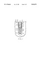
- FIG. 7 is a partial cut-away view through a third embodiment of the suture anchor emplaced in a bone hole
- FIG. 8 illustrates deployment of the suture anchor of FIG. 7, in which FIG. 8A illustrates deployment of the suture anchor and FIG. 8B illustrates removal of the insertion stem from the bone hole;
- FIG. 9 is a partial, cut-away view of deployment of the suture anchor of FIG. 1 using a pop-rivet gun;
- FIG. 10 is cut-away view of another embodiment of the suture anchor deployment device
- FIG. 11 is a cross-sectional view of a hand-held deployment means used with the device of FIG. 10;
- FIG. 12 is a cut-away view of a device and method for removing the suture anchor of the present invention.
- FIG. 13A is an exploded view of a preferred suture anchor device of the invention.
- FIG. 13B depicts the suture anchor of FIG. 13A partially assembled
- FIG. 14 depicts in cross-section a preferred anchoring element of the suture anchoring device of FIG. 13A;
- FIG. 15 depicts in side view a preferred expander element of the suture anchoring device of FIG. 13A;
- FIGS. 16 and 17 depict an insertion stem incorporated in a preferred suture anchor assembly according to the invention.
- FIGS. 18 and 19 depict an anchoring element incorporated in a preferred suture anchor assembly according to the invention.
- FIG. 20 depicts an expander element incorporated in a preferred suture anchor assembly according to the invention.
- FIGS. 21-22 depicts a suture anchor device according to the invention including two anchoring elements.
- the suture anchor assembly generally includes an elongated insertion stem and an approximately cylindrical anchoring element having an axial channel for receiving the insertion stem.
- the anchoring element In its nonexpanded state, the anchoring element can be placed into a pre-drilled opening in a bone.
- An expander element is engaged with a proximal end of the anchoring element.
- proximal refers to a point that is spaced-apart from the bottom of a bone hole in a direction towards the point of origin of the assembly (i.e. towards the surgeon), as opposed to a "distal" point that is closer to the bottom of the bone hole (i.e. farthest from the point of origin; the surgeon).
- the anchoring element is capable of moving proximally within the bone hole (i.e. towards the bone surface) so that the proximal end of the anchoring element telescopes over a distal end of the expander element.
- resilient proximal portions of the anchoring element are forced outward against the expander element, causing the resilient proximal portions of the anchoring element to expand into the bone hole, fixing the anchoring element in a pressure fit firmly within the opening.
- Telescopes has its commonly understood meaning in this context and refers to surfaces that slide against each other in which one surface is forced into another. In particular, the distal end of the expander is forced into the proximal end of the moving anchoring element.
- FIG. 1 illustrates an exploded view of one embodiment of the suture anchor assembly of the invention containing an insertion stem onto which is loaded an anchoring element and an expander element.
- One component of the suture anchor assembly 10 is an insertion stem 12, an elongated cylinder having distal 14 and proximal 16 ends.
- Distal end 14 is preferably formed as a shoulder 15 designed to engage a distal end 24 of an anchoring element 20.
- the insertion stem 12 has a frangible portion 18 disposed some distance proximal to end 14.
- frangible refers to a portion of stem 12 that is breakable or fragile.
- FIG. 1 illustrates frangible portion 18 as a section of stem 12 having a thinner diameter than the remainder of the stem.
- the frangible section 18 is designed to sever or break when sufficient tension is applied to the stem 12 in a proximal direction (shown by arrow A) that is parallel to longitudinal axis (B--B) of the stem.
- the frangible portion may be other than a thin-walled section of stem 12 and may include a series of spokes or webbing or a plurality of very attenuated membranes.
- Anchoring element 20 is substantially tubular, having opposed proximal 22 and distal 24 ends connected by way of a central axial channel 26 extending from the proximal end 22 of element 20 to the distal end 24 of the element. Distal end 24 is engaged with shoulder 15 of stem 12.
- Element 20 has inner 28 and outer 30 peripheral surfaces forming a wall. Defined in the wall, and in communication with axial channel 26, are a series of axially-oriented slots 34 that begin at the proximal end 22 and extend some distance towards the distal end 24.
- Each of the series of axially-oriented slots 34 in the anchoring element 20 define a flexible wall section 33 located between each slot.
- Each wall section 33 is more flexible at its respective proximal end, in part because the wall section is defined between slots that extend directly from the proximal end 22 of the anchoring element.
- the distal ends of the respective wall sections 33 are co-extensive with the distal end 24 of anchoring element 20.
- FIG. 1 also illustrates a suture retainer 48 located adjacent the distal end 24 of anchoring element 20.
- Suture retainer 48 is most preferably an aperture for receiving an intermediate portion of a suture (i.e. a segment between the free ends of the suture). This allows the anchoring element to be a so-called “slidable" suture anchor.
- the suture retainer may be configured in a variety of other ways, including any number of suture retaining configurations, such as a slit, a groove, a clip or wire and the like (e.g., suture engaging slot 221 of stem 212, described above).
- Expander element 35 is substantially tubular, having opposed proximal 38 and distal 40 ends connected by way of a central axial channel 36, the axial channel defining a longitudinal axis (D--D).
- the respective inner diameters of the expander element 35 and anchoring element 20 are of sufficient size to allow them to be loaded onto stem 12, anchoring element 20 being engaged first, so that proximal end 22 of the anchoring element 20 is engaged in facing relationship to distal end 40 of expander element 35.
- FIG. 2 illustrates in partial cross-section the configuration resulting when anchoring element 20 and expander element 35 are disposed by way of stem 12 into a hole 41 drilled in a bone 42.
- the proximal end 22 of each of the flexible wall sections 33 has a camming surface 44 that is designed to mate with a corresponding camming surface 46 at the distal end of the expander element 35.
- the camming surface 46 of expander element 35 is preferably tapered or beveled, the taper ranging from about 10 degrees to about 45 degrees, relative to axes (B--B) and (D--D). Most preferably, the tapered camming surface is at an angle of about 30° degrees relative to these longitudinal axes.
- Corresponding tapered camming surfaces 44 of the anchoring element 20 are also disposed at the proximal end 22 of wall sections 33.
- FIGS. 3 and 4 illustrate operation of this embodiment of the suture assembly and the forces imposed on the components of the assembly in order to set the suture anchor into a bone hole 41.
- Expander element 35 is substantially fixed at the bone surface 47 and this may be accomplished by using an expander element 35 containing a flange 50 that is integral with the proximal end 38 of element 35 and extending radially outwardly around the periphery of the proximal end 38.
- flange 50 serves as a support/countersink to brace the expander element 35 against the bone surface 47 and against a housing 57 of the stem 12 (Shown in FIG. 4) to provide a solid surface onto which a force is exerted that is opposite to the tension force applied to stem 12.
- stem 12 When tension is applied to stem 12 (in the direction shown by arrow A), the stem 12 and anchoring element 20 are forced in the indicated direction (i.e. proximal to the bone hole) but the expander element 35 remains substantially immobile within the bone hole 41 as the result of a distally-applied counterforce (arrow X) exerted against flange 50 by a distal end 59 of the stem housing 57 (See also FIG. 6).
- a proximally directed force that is substantially equal in magnitude and in direction to the stem tension force (arrow A) is applied to the proximal end of anchoring element 20.
- the anchoring element moves proximally in the bone hole and camming surfaces 44, 46 are forced into mating engagement.
- anchoring element 20 telescopes over the substantially fixed expander element 35.
- distal camming surfaces 46 of expander element 35 remain substantially fixed in position within the bone hole and proximal camming surfaces 44 of anchoring element 20 are forced to ride over them.
- Wall sections 33 defined between the series of axially-oriented slots 34 are flexible and will expand into the bone when the camming surfaces are mutually engaged and the anchoring element 20 telescopes over the expander element 35 when tension is applied to the stem 12.
- Wall sections 33 have proximal ends that are more flexible then other portions thereof.
- expansion of the wall sections 33 by the telescoping movement of the anchoring element 20 over the fixed expander element 35 results in the wall sections 33 having a substantially arcuate cross section when fully deployed and expanded in the bone, the proximal ends of the wall sections being driven radially outward and in an oblique direction (i.e., at an angle relative to the longitudinal axis of the stem).
- the frangible portion 18 of stem 12 is adapted to break when the flexible wall sections are in their fully expanded position. Once severed, the stem 12 may be removed from the rest of the assembly, leaving the anchoring element 20, expander element 35 and attached suture (not illustrated) locked in the bone hole (See FIG. 5).
- the frangible portion 18 of insertion stem 12 is preferably located at a distance above the distal end 14 of the stem so that, when the stem is removed, the remaining severed stub of the insertion stem does not extend above the level of the bone surface 47.
- FIG. 6 is a partial, plan section of a bone hole 41 into which a non-flanged expander element 35 is disposed.
- the distal end 59 of stem housing 57 is wide enough so that it is partially coextensive with the bone hole 41 opening and thus simultaneously contacts both the bone surface 47 and proximal end 38 of expander element 35. Functionally, this configuration may be considered similar to that of FIG.
- distal portions of insertion stem 12 may include screw threads 52 for mating engagement with corresponding screw threads 54 on the inner surface 28 of anchoring element 20.
- Stem 12 includes a proximal slot 49 for engagement with a screwdriver.
- Expander element 35 may include proximal flange 50 and stem 12 is rotatable within the expander 35. Expander element 35 is countersunk into the bone so that flange 50 rests upon a shoulder 51 defined in the wall 53 of the bone hole 41.
- the screw threads 52,54 provide for positioning of the anchoring element 20 in the hole 41 at its desired depth and for applying a desired telescoping force to the anchoring element by turning the insertion stem 12 into the axial channel 26 of the anchoring element 20.
- the distal end 14 of insertion stem 12 and the distal end 24 of anchoring element 20 are attached as an integral unit so that only the expander element 35 need be loaded onto the insertion stem.
- the assembly may comprise the integral anchoring element and insertion stem and an expander element that is molded to, or extruded integrally with, a distal end of a housing as described below with reference to FIG. 9.
- Element 20 is preferably constructed of a biocompatible material.
- biocompatible means that the anchoring element material is chemically and biologically inert.
- Suitable materials for the anchoring element include, for example, an implant grade high density polyethylene, low density polyethylene (PE 6010 and PE 2030); acetal (trademark “Delrin", manufactured by Dupont Chemical Co.) and polypropylene (13R9A and 23M2: all made by Rexene, Dallas, Tex.). Of these, PE 6010 and 13R9A have been FDA listed as class 6 materials.
- the anchoring element may also be bioabsorbable.
- bioabsorbable refers to those materials that are meant to be decomposed or degraded by bodily fluids, such as, for example, blood and lymph.
- the anchoring element is preferably made from a biodegradable polymer or copolymer of a type selected in accordance with the desired degradation time. That time in turn depends upon the anticipated healing time of the tissue which is the subject of the surgical procedure.
- Known bioabsorbable polymers and copolymers range in degradation time from about 3 months for polyglycolide to about 48 months for polyglutamic-co-leucine.
- a common bioabsorbable polymer used in absorbable sutures is poly (L-lactide) which has a degradation time of about 12 to 18 months.
- the preferred anchoring element is comprised of an absorbable copolymer derived from glycolic and lactic acids, such as a synthetic polyester chemically similar to other commercially available glycolide and lactide copolymers. Glycolide and lactide degrade and absorb in the body by hydrolysis into lactic acid and glycolic acid which are then metabolized by the body.
- a preferred deployment apparatus of the invention retains the insertion stem, expander element and anchoring element prior to emplacement and includes a tool for exerting tension on the insertion stem.
- the preferred apparatus also allows for separating the insertion stem and expander element from the anchoring element after the frangible section is severed.
- FIG. 9 is a partial, plan view illustrating one embodiment of a deployment apparatus of the invention and its mode of operation.
- the insertion stem 12 is pre-loaded with the anchoring element 20 and the expander element 35 and the stem 12 is then placed into an apparatus similar to a pop-rivet gun 56.
- the stem 12 is encased within a housing 57 of the apparatus so that a toothed collet 58 or other similar grasping means engages the insertion stem 12.
- the anchor assembly is then placed in a hole 41 drilled into a bone 42 and a distal end 59 of the housing 57 is pressed into contact with the bone surface 47. This helps fix the flange 50 of expander element 35 into position at the bone surface 47.
- Activation of the apparatus 56 retracts the insertion stem 12 proximally (arrow A) to induce tension on the stem.
- the camming surfaces 44,46 of the respective anchor 20 and expander 35 elements come into telescoping contact and the flexible wall sections 33 of anchoring element 35 are set into the bone 42.
- Tension is continually exerted on stem 12 until the stem shears off from the remainder of the suture assembly at the frangible section 18.
- expander element 35 is molded or extruded integrally as one-piece with distal end 59 of housing 57, once the stem is sheared the rest of the stem and the expander element are removed to leave the anchoring element with its attached suture (and severed stem) in the bone.
- the expander element is not integral with the housing, the severed stem and the expander element are left in the bone.
- FIG. 10 illustrates another embodiment of an emplacement apparatus of the invention and its mode of operation.
- the apparatus includes a housing 57 which encloses insertion stem 12 held co-axially in place by a toothed collet 58.
- the proximal end 60 of the housing 57 is engaged with arms 90 of a push rod 92 in the shape of an inverse T.
- Proximal end 60 of housing 57 also includes an aperture (not shown) for receiving the collet 58.
- the collet 58 is integral with a bayonet-type connector 64 that allows the combined connector and housing to be removably attached to a hand held means 120 (See FIG. 11).
- the stem 12 is thus co-axially arranged around the collet 58 and the collet can move co-axially within the housing 57.
- the anchoring element 20 and expander element 35 are threaded on the stem and the stem 12 is positioned in the collet.
- the hand-held means 120 is of similar design to the hand held means described in co-pending and commonly assigned patent application Ser. No. 08/163,130, "Bone Fastener", filed Dec. 6, 1993, incorporated herein by reference.
- the hand held means 120 consists of two handle elements 122, 124 slidably engaged to provide a comfortable pistol grip 126 by which handle element 124 can be moved in a proximal-distal direction with respect to the handle element 122 by squeezing the pistol grip 126.
- the distal end 123 of the handle element 122 is adapted for removably mounting the bayonet connector 64.
- the distal end 125 of handle element 124 includes a rod 129 whose distal end 127 abuts push rod 92 when the handle elements are assembled and the connector 64 is mounted onto end 123 of handle element 122.
- the surgeon grasps the apparatus by the pistol grip 126, and directs the anchoring assembly into the predrilled hole in the bone.
- the surgeon squeezes the grip 126 sliding the handle 124 frontward with respect to the handle element 122, as indicated by the arrow 131.
- Rod 129 presses against push rod 92 in the distal direction (arrow X in FIG. 10) and the downward force is transmitted through the inverse-T arms 90 to the housing 57 and against the bone surface 47.
- the connector 64 and attached co-axially moveable stem 12 are urged proximally (arrow A), translating the distal force on the push rod 92 to a proximal, tensioning force on the insertion stem 12.
- a significant feature of the present suture assembly is that the anchor element may be removed after deployment by forcing the anchoring element distally back down into the bone hole 41.
- a removal apparatus as illustrated in FIG. 12 consists of a cannulated rod 60 whose distal end 62 is adapted to engage with distal end 24 of anchoring element 20 or with the severed end of the insertion stem 12 at the frangible section. As illustrated, rod 60 is engaged with anchoring element 20 and pressed distally (arrow F) to drive the anchor element 20 back down into the bone hole until the flexible wall sections 33 are substantially parallel to the longitudinal axis (F--F) of the bone hole and extend in a proximal -distal direction.
- a sheath 64 is then slid (arrow G) over the rod 60 to engage outer peripheral surfaces of the anchoring element 20. This engagement may be facilitated by a series of detents (not shown) located on the distal end 65 of sheath 64 which fixedly engages the anchoring element.
- the anchoring element, any insertion stem remaining, and sheath are removed (arrow H) from the bone hole as a unit.
- a surgeon takes the sharpened proximal end of a K-wire (manufactured, for example, by Kirschner Medical Company) and spears the tissue that is to be attached.
- the proximal end of the K-wire is then placed over the bone surface at the approximate site of attachment.
- the K-wire is then drilled into the bone at that site. If the location is where the surgeon wants it, the surgeon then threads a cannulated drill of the appropriate size over the K-wire. A hole is then drilled into the bone using the cannulated drill. Then drill and K-wire is are removed. It will be understood that the use of a K-wire is not essential to this method of drilling a bone hole.
- the suture assembly of the invention is then loaded within an emplacement apparatus (for example, described above with reference to FIGS. 9-11).
- the assembly is pressed downwards through the tissue and into the bone hole so that the anchoring element is emplaced into the bone hole.
- the emplacement apparatus is triggered by applying a tensional force to the insertion stem so that the proximal end of the anchoring element telescopes over the distal end of the expander element.
- the outer, flexible surfaces of the anchoring element engage with the bone and the insertion stem is released from the anchoring element to set the anchor element within the bone hole.
- the apparatus is removed.
- Other variations on this technique include first drilling a bone hole and then punching a hole through the soft tissue. The tissue is then moved over the bone hole using, for example, a K-wire or a suture passer grasping device.
- the force needed to telescope the anchoring element may be substantially continuous and spread out over time.
- the anchoring element is telescoped over the expander element with a compressive motion that is axially delivered in a direction substantially parallel to the longitudinal axis of the insertion stem.
- the apparatus for deploying the present assembly requires an advancing drive mechanism which lacks any impact or impulse characteristics.
- kits may include an anchoring element of the invention; an insertion stem of the invention and a holder for engaging with the anchoring element, the holder capable of maintaining the anchoring element in position with the bone opening.
- kits may include a grasper/manipulator for grasping free ends of the suture to pass the suture through soft tissue.
- a suture-grasping device is described in commonly assigned and co-pending application Ser. No. 08/097,154, filed 26 Jul. 1993, incorporated herein by reference.
- a K-wire, drill and drill guide may also be also included.
- the kit is encased in a sterile tray or other receptacle for use by an operator at a site.
- Anchors were attached to sutures and were set using the procedures described herein into an artificial bone made of foam made by Sawbones, Inc., P.O. Box 589, Vashon, Wash. 98070. Tension was applied to the sutures by a stainless steel hardened wire attached to the back of the anchor. Tension was measured by a force gauge. The foam/suture assembly was observed for anchor failure. Results are presented below in the Table.
- FIG. 13A depicts an insertion stem 212 according to a preferred practice of the invention.
- the stem 212 is elongate and has distal 214 and proximal 216 ends.
- Distal end 214 is formed with a shoulder (or head) 215 designed to engage a distal end 224 of an anchoring element 220.
- the insertion stem 212 has a frangible portion 218, disposed some distance proximal from end 214, and designed to sever or break when sufficient tension is applied to the stem 212 in a proximal direction parallel to longitudinal axis of the stem.
- the frangible portion may be other than a thin-walled section of stem 12 and may include a series of spokes or webbing or a plurality of very attenuated membranes.
- the stem 212 includes threading 217 for threaded engagement by the deployment apparatus of FIGS. 9-11. Ridges 219, which are disposed distal of frangible portion 218 of stem 212, provide ratchet-like retention of the expander element 235 in the assembled suture anchor assembly, thereby preventing unwanted or excess movement of the expander element relative to the anchoring and insertion elements. Suture engaging slot 221 provides a track in which a loop of a suture may be retained, thereby providing additional control over the suture, e.g., for purposes of knot-tying.
- anchoring element 220 is substantially tubular, having opposed proximal 222 and distal 224 ends connected by way of a central axial channel (not shown) extending from the proximal end 222 to the distal end 224. Distal end 224 engages with shoulder 215 of stem 212.
- element 220 has inner and outer peripheral surfaces forming a wall. Defined in the wall, and in communication with the axial channel, are a series of axially-oriented slots 234 that begin at the proximal end 222 and extend some distance towards the distal end 224.
- Each of the series of axially-oriented slots 234 in the anchoring element 220 define a flexible wall section 233 located between each slot.
- the anchoring element can include a plurality of slots 234 and, thereby, a corresponding number of wall sections 233. Although the number of slots (and wall sections) can range from 2 to 10 (or upwards), a preferred number of slots (and wall sections) is three or four.
- each wall section 233 tapers gradually from a base portion 231 to the proximal end 222. That taper can be, for example, 0° to 20° degrees and, preferrably, is about 8°.
- Camming surfaces 244 at the tips of the walls have more pronounced tapers. These can range, e.g., from 30° to 75° and is, preferrably, about 60°.
- a preferred expander element 235 like element 35 depicted in FIG. 1 and described in connection therewith, has opposed proximal 238 and distal 240 ends connected by way of a central axial channel 236.
- the diameter of channel 236 is of sufficient size to allow it to be loaded onto stem 212, along with anchoring element 220, so that proximal end 222 of the anchoring element 220 is engaged in facing relationship to distal end 240 of expander element 235.
- FIG. 13B which illustrates in partial cross-section the configuration resulting when anchoring element 220 and expander element 235 are are readied for assembly on stem 212.
- each of the flexible wall sections 233 of anchoring element 220 has a camming surface 244 that is designed to mate with a corresponding camming surface 246 at the distal end of the expander element 235.
- the camming surface 246 of expander element 235 is tapered at approximately 45°, though that taper can be as little as about 10° and as much as 60°.
- the expander element 235 includes projections or wings 237, each of which corresponds with a slot 234 of anchoring element 220.
- the wings 237 slidingly engage with slots 234 as the suture anchor system is being assembled. This permits the anchoring element 220 to telescope or cam over expander element 235 until the wings 237 reach the bottoms 229 of their respective slots 234.
- the anchoring element 220 can include an internal shoulder, or other such protrusion, that prevents the anchoring element 220 from telescoping or camming too far over expander element 235.
- the expander element 235 is shown in side view at FIG. 15. There, it is seen that the element 235 has a height (i.e., length along the longitudinal axis) less than that of the sides 233 of the anchoring element 220. Preferrably, the height of element 235 is approximately one-half that of the sides 233 and, still more preferably, a height substantially equal to that of the camming surface 244.
- the insertion stem 212 incorporates a suture retaining slot 221 that provides a track in which the suture (not shown) is slidingly engaged as it loops over the head 215 of the insertion stem.
- This slot prevents the suture from sliding off the head 215 during suture knot-tying or during and subsequent to emplacement of the anchor assembly in the bone.
- the suture retaining slot may be said to reside at the distal end of the anchoring element 220.
- looping a suture over the head 215 provides added strength to the overall assembly. Particularly, when the suture is under tension (e.g., during and subsequent to tying), the suture retaining slot is in compression, as are head 215 and adjacent portions of the stem 212. This configuration gives the suture retainer (and, therefore, the assembly as a whole) greater strength then found in configurations (such as where a suture-retaining aperture is disposed at the proximal end of the insertion stem 212) in which the suture retainer is placed under tension when the suture itself is under tension.
- Alternatives to the illustrated slot include placing an aperture (e.g., hole) through which the suture can be tied, or a shoulder around which the suture can be looped, at locations on anchoring element 220 or insertion stem head 215 that are distal to the slot ends 229 of the assembled suture anchor device.
- an aperture e.g., hole
- a track 314 extends from the slot 221 toward the proximal end of the stem 212. This serves to guide and protect the suture from being crimped by the anchor assembly during and subsequent to its emplacement in bone.
- the slot and track widths are sized in accord with the expected suture gauge. Preferably, the width is such that the suture can slide freely without excessive width-wise play.
- the slot and track depths are likewise determined by the expected suture gauge.
- FIG. 17 depicts a side cut-away view of insertion stem 212 and shows the shape of the support base (or floor) 316, at the base of the slot 221 and track 314, supporting the suture.
- the support base 316 runs longitudinally, parallel to the major axis of the stem 212 and ends in a tear drop shape 318 at the distal end of the stem, i.e., at slot 221, where the suture loops over head 215.
- the tear drop shape is advantageous over a conventional rectilinear shape insofar as the tear drop distributes over a greater surface area the compressional load applied to the head 215 by the suture, e.g., during and subsequent to its being tied.
- the tear drop opens at an angle of 30°-60° and, more preferably, of 41° beginning a point distal to the proximal side 320 of the head.
- the "corners" of the tear drop 318 define a radius R 1 of 0.001-0.020 inches and, preferably, 0.010 inches for a #2 suture. Proportionally sized radii can be selected for where the expected suture gauge differs from this.
- the stem 212 incorporates a chamfer at the junction of the elongate portion of the stem and head 215.
- the chamfer 312 which is angled at 20°-70° and, more preferably, 45°, also serves to reduce the concentration of tensional stress on head 215 during and subsequent to emplacement of the anchor assembly in bone.
- chamfer refers to conventional straight-edge chamfers, as well as blend radii.
- the stem 212 incorporates a reverse taper 310 in place of ridges 219 discussed above.
- the taper 310 which is exaggerated in the drawing for visualization purposes, describes an included angle of 1°-10° and, preferably, of 2°, relative to the longitudinal axis of the stem 212.
- the reverse taper serves to prevent unwanted or excess movement of the expander element relative to the anchoring and insertion elements.
- the anchoring element incorporates a number of features to distribute the stresses of emplacement. This gives smaller assemblies, which may be constructed from polymers and copolymers (as described above), greater holding strength without risk of failure. As shown in FIGS. 18 and 19, stress distribution is accomplished by rounding, or chamfering, stress-bearing edges of the walls 233 and slots bases 229, as well as by tapering the walls, in order to distribute applied loads.
- the distal ends 229 of the slots of anchoring element 220 are rounded. This reduces stress on, and thereby prevents failure of, the anchoring element 220 in the region adjacent to those rounded distal ends.
- the rounded ends of the slots 234 define radii R 2 of 0.001-0.020 in and, preferably, 0.010 in for a three-wing or four-wing polymer anchor having an outside diameter of 3.5 mm, an inside diamter of 2 mm, an overall length of 5.5 mm, and a wing length of 3 mm. Proportionally sized radii can be selected for anchoring elements whose dimensions differ from this.
- the slots 234 are tapered. Particularly, they are wider at the proximal end then at the distal end.
- the degree of taper may vary from 0°-10° and, preferably, is about 2°. This taper also reduces the stress on, and thereby prevents failure of, the anchoring element 220 in the region adjacent to the distal ends of the slots 234.
- FIG. 19 is a top view of a preferred anchoring element 220 according to the invention.
- the edges of wall sections 233 are chamfered to reduce stress during and subsequent to emplacement of the assembly in bone. More particularly, each wall section 233 is chamfered along its inner-top edge 330, as well as along the edges of the slot 234 that defines its inner-side edges 332, as shown. Chamfering along the inner-top edge 330 is preferably accomplished via a blend radius.
- the inner-side edges 332 are also chamfered by a blend radius of, e.g., of 0.001-0.020 inches and, preferably, 0.010 inches for a three-wing or four-wing anchor having dimensions as specified above. Again, proportionally sized radii can be selected for anchoring elements whose dimensions differ from this. This chamfering continues along the entire inside edge of each slot 234, including the inside edge 334 at the bottom 229 of each slot.
- a preferred expander element 235 can have camming surfaces 340 that are rounded in order to mate with the chamfered inner-top edge 330 of expander element 220.
- the surface 340 can have an overall angle tapered at approximately 45° (or little as about 10° and as much as 60°). It is rounded to a degree sufficient to allow the wings of the anchoring element to cam over the expander element when opposing force is applied to the anchoring element.
- FIG. 21 depicts a suture anchor assembly according to a further embodiment of the invention incorporating two anchoring elements for added strength.
- the assembly includes, stem 212, anchoring element 220 and expander element 235, as well as additional anchoring element 350.
- the additional anchoring element 350 is disposed between expander element 235 and the anchoring element 220.
- Element 350 is constructed in the same manner as element 220 except insofar as its distal end 352 has chamfered camming surfaces 354 similar to surfaces 340 of expander element 235. As above, those camming surfaces 354 can be straight chamfers or blended radii. In either event the surfaces are angled and/or rounded to a sufficient degree allow the wings of the anchoring element 220 to cam over the distal end 352 of element 350 upon assembly of the device, as shown in FIG. 22.
- a suture anchor assembly may include a plurality of tubular anchoring elements 220, 350, loaded “in series” on the stem 212 as shown.
- a distal-most anchoring element 220 has its distal end in engagement with the proximal side 320 of the stem's head, while the other anchoring elements 350 having their distal ends in engagement with a proximal end of the adjacent anchoring element.
- the proximal-most anchoring element 350 moves proximally within the bone hole (not shown) from a first position, where that anchoring element's proximal end is engaged with the distal end of the expander element 235, to a second position, where the proximal end cams over the distal end so that flexible wall sections expand, as shown in FIG. 22, into a wall of the bone hole.
- the other anchoring element 220 is adapted for proximal movement within the bone hole from its respective first position, where its proximal end is engaged with the distal end of the adjacent anchoring element 350, to a respective second position, where that proximal end cams over that distal ends, as shown in FIG. 22, so that the respective flexible wall sections expand into a wall of the bone hole.
- FIGS. 21 and 22 show only two anchoring element, those skilled in the art will appreciate that still further embodiments of the invention may include three or more anchoring elements.
- FIGS. 13A-20 A further appreciation of an exemplary apparatus of the type shown in FIGS. 13A-20 may be attained by reference to the three-dimensional drawings shown in the Appendix filed herewith.
Abstract
Description
              TABLE
______________________________________
Polycaprolactone        Poly (L-lactide)
Poly (DL-lactide)       Polyglycolide
95:5 Poly (DL-lactide-co-glycolide)
                        Polydioxanone
Polyesteramides
Copolyoxalates
Polycarbonates
Poly (glutamic-co-leucine)
90:10 Poly (DL-lactide-co-glycolide)
85:15 Poly (DL-lactide-co-glycolide)
75:25 Poly (DL-lactide-co-glycolide)
50:50 Poly (DL-lactide-co-glycolide)
90:10 Poly (DL-lactide-co-caprolactone)
75:25 Poly (DL-lactide-co-caprolactone)
50:50 Poly (DL-lactide-co-caprolactone)
______________________________________
______________________________________
Diameter
       Wall    Force
(mm)   (inches)
               (lb)      Observations
______________________________________
2.8    0.018   29.0      Failure; 3 wall sections bent
                         back on themselves; foam cone
                         pulled out 0.25" diameter
       0.024   32.8      Failure; 4 wall sections bent
                         back on themselves; foam cone
                         pulled out 0.23" diameter
       0.035   33.4      Failure; 4 wall sections bent
                         back on themselves; foam cone
                         pulled out 0.23" diameter
3.5    0.018   37.2      Failure; anchor broken with
                         half pulled through; wall
                         sections on the broken half
                         were straight.
       0.018   43.0      Failure; wall sections bent back
                         over themselves
3.8    0.025   33.0      No anchor failure; foam bone
                         wedge pulled out and only 2 wall
                         sections were spread; foam
                         pullout .5" diameter/.25" deep
       0.025   51.0      No anchor failure; all wall
                         sections spread; foam bone
                         wedge pulled out; .75:
                         diameter/.25" deep
______________________________________
Claims (32)
Priority Applications (7)
| Application Number | Priority Date | Filing Date | Title |
|---|---|---|---|
| US08/719,659 US5814071A (en) | 1994-11-10 | 1996-09-25 | Suture anchor assembly and methods |
| DE69739832T DE69739832D1 (en) | 1996-09-25 | 1997-09-25 | NÄHFADENANKERANORDNUNG |
| PCT/US1997/017236 WO1998012972A1 (en) | 1996-09-25 | 1997-09-25 | Suture anchor assembly and methods |
| JP51591098A JP4434316B2 (en) | 1996-09-25 | 1997-09-25 | Suture anchor assembly |
| ES97944458T ES2341153T3 (en) | 1996-09-25 | 1997-09-25 | SUTURE ANCHOR SET. |
| EP97944458A EP0951238B1 (en) | 1996-09-25 | 1997-09-25 | Suture anchor assembly |
| AU45946/97A AU719350B2 (en) | 1996-09-25 | 1997-09-25 | Suture anchor assembly and methods |
Applications Claiming Priority (4)
| Application Number | Priority Date | Filing Date | Title |
|---|---|---|---|
| US08/337,944 US5649963A (en) | 1994-11-10 | 1994-11-10 | Suture anchor assembly and methods |
| US08/568,348 US5797963A (en) | 1994-11-10 | 1995-12-06 | Suture anchor assembly and methods |
| US08/574,463 US5643321A (en) | 1994-11-10 | 1995-12-07 | Suture anchor assembly and methods |
| US08/719,659 US5814071A (en) | 1994-11-10 | 1996-09-25 | Suture anchor assembly and methods |
Related Parent Applications (3)
| Application Number | Title | Priority Date | Filing Date |
|---|---|---|---|
| US08/337,944 Continuation-In-Part US5649963A (en) | 1994-11-10 | 1994-11-10 | Suture anchor assembly and methods |
| US08/568,348 Continuation-In-Part US5797963A (en) | 1994-11-10 | 1995-12-06 | Suture anchor assembly and methods |
| US08/574,463 Continuation-In-Part US5643321A (en) | 1994-11-10 | 1995-12-07 | Suture anchor assembly and methods |
Publications (1)
| Publication Number | Publication Date |
|---|---|
| US5814071A true US5814071A (en) | 1998-09-29 |
Family
ID=24890876
Family Applications (1)
| Application Number | Title | Priority Date | Filing Date |
|---|---|---|---|
| US08/719,659 Expired - Lifetime US5814071A (en) | 1994-11-10 | 1996-09-25 | Suture anchor assembly and methods |
Country Status (7)
| Country | Link |
|---|---|
| US (1) | US5814071A (en) |
| EP (1) | EP0951238B1 (en) |
| JP (1) | JP4434316B2 (en) |
| AU (1) | AU719350B2 (en) |
| DE (1) | DE69739832D1 (en) |
| ES (1) | ES2341153T3 (en) |
| WO (1) | WO1998012972A1 (en) |
Cited By (217)
| Publication number | Priority date | Publication date | Assignee | Title |
|---|---|---|---|---|
| US6033429A (en) * | 1998-01-13 | 2000-03-07 | Cardiac Assist Technologies, Inc. | System, apparatus and method for closing severed bone or tissue of a patient |
| US6045572A (en) * | 1998-10-16 | 2000-04-04 | Cardiac Assist Technologies, Inc. | System, method and apparatus for sternal closure |
| US6080185A (en) * | 1998-10-16 | 2000-06-27 | Cardiac Assist Technologies, Inc. | Stop mechanism and method therefor |
| US6096041A (en) | 1998-01-27 | 2000-08-01 | Scimed Life Systems, Inc. | Bone anchors for bone anchor implantation device |
| US6264676B1 (en) | 1996-11-08 | 2001-07-24 | Scimed Life Systems, Inc. | Protective sheath for transvaginal anchor implantation devices |
| US6306158B1 (en) | 1999-03-02 | 2001-10-23 | Edwin C. Bartlett | Suture anchor and associated method of implantation |
| US6319272B1 (en) | 1996-11-08 | 2001-11-20 | Boston Scientific Corporation | Transvaginal anchor implantation device and method of use |
| WO2002053039A1 (en) * | 2000-12-28 | 2002-07-11 | Artimplant Ab | A device for fixing an object by a hole in bone tissue |
| US20020173558A1 (en) * | 1999-03-25 | 2002-11-21 | Metabolix, Inc. | Medical devices and applications of polyhydroxyalkanoate polymers |
| US6491714B1 (en) * | 1996-05-03 | 2002-12-10 | William F. Bennett | Surgical tissue repair and attachment apparatus and method |
| US6540770B1 (en) * | 1998-04-21 | 2003-04-01 | Tornier Sa | Reversible fixation device for securing an implant in bone |
| US20030135269A1 (en) * | 2002-01-16 | 2003-07-17 | Swanstrom Lee L. | Laparoscopic-assisted endovascular/endoluminal graft placement |
| US6641596B1 (en) * | 2000-10-18 | 2003-11-04 | Ethicon, Inc. | Knotless bioabsorbable suture anchor system and method |
| US6652561B1 (en) | 2000-10-13 | 2003-11-25 | Opus Medical, Inc | Method and apparatus for attaching connective tissues to bone using a perforated suture anchoring device |
| US6689153B1 (en) | 1999-04-16 | 2004-02-10 | Orthopaedic Biosystems Ltd, Inc. | Methods and apparatus for a coated anchoring device and/or suture |
| US6692516B2 (en) | 2000-11-28 | 2004-02-17 | Linvatec Corporation | Knotless suture anchor and method for knotlessly securing tissue |
| US6743233B1 (en) | 2000-08-02 | 2004-06-01 | Orthopaedic Biosystems, Ltd., Inc. | Medical screw and method of installation |
| US6780198B1 (en) * | 2001-12-06 | 2004-08-24 | Opus Medical, Inc. | Bone anchor insertion device |
| US6833005B1 (en) | 2001-02-02 | 2004-12-21 | John P. Mantas | Ligament graft system and method |
| US6840943B2 (en) | 2000-09-22 | 2005-01-11 | Codman & Shurtleff, Inc | Instrument and method for applying surgical fasteners |
| US6843799B2 (en) | 2002-03-25 | 2005-01-18 | Edwin C. Bartlett | Suture anchor system and associated method |
| US6846313B1 (en) | 1998-11-03 | 2005-01-25 | Codman & Shurtleff, Inc. | One-piece biocompatible absorbable rivet and pin for use in surgical procedures |
| US20050070926A1 (en) * | 2003-09-30 | 2005-03-31 | Ortiz Mark S. | Applier for fastener for single lumen access anastomosis |
| US20050216038A1 (en) * | 2001-06-14 | 2005-09-29 | Suturtek Incorporated | Apparatus for surgical suturing with thread management |
| US20050251264A1 (en) * | 2004-05-04 | 2005-11-10 | Biopro. Inc. | Subtalar implant |
| EP1604616A2 (en) * | 1999-10-30 | 2005-12-14 | Aesculap AG & Co. KG | Surgical instrument for fixation of adjacent bone plates |
| US20060041315A1 (en) * | 2004-05-04 | 2006-02-23 | Biopro, Inc. | Subtalar implant |
| US20060064094A1 (en) * | 1998-10-26 | 2006-03-23 | Expanding Orthopedics, Inc. | Expandable orthopedic device |
| US20060069396A1 (en) * | 2004-09-20 | 2006-03-30 | Suturtek Incorporated | Apparatus and method for minimally invasive suturing |
| US20060106422A1 (en) * | 2004-11-16 | 2006-05-18 | Del Rio Eddy W | Anchor/suture used for medical procedures |
| US20060106423A1 (en) * | 2004-09-28 | 2006-05-18 | Thomas Weisel | Suture anchor |
| US20060177513A1 (en) * | 2005-01-28 | 2006-08-10 | Tepha, Inc. | Embolization using poly-4-hydroxybutyrate particles |
| US20060217748A1 (en) * | 2003-09-30 | 2006-09-28 | Ethicon Endo-Surgery, Inc. | Method for Hybrid Gastro-Jejunostomy |
| WO2006103598A1 (en) * | 2005-03-31 | 2006-10-05 | Bächler Feintech Ag | Device for fixing a ligament |
| US20060235413A1 (en) * | 2004-12-07 | 2006-10-19 | Arthrotek, Inc. | Expanding suture anchor having an actuator pin |
| US20060281970A1 (en) * | 2005-06-13 | 2006-12-14 | Stokes Michael J | Attachment apparatus for coupling with an endoscope |
| US20060282092A1 (en) * | 2005-06-13 | 2006-12-14 | Stokes Michael J | Surgical suturing apparatus with needle position indicator |
| US20060282091A1 (en) * | 2005-06-13 | 2006-12-14 | Shelton Frederick E Iv | Adjustable vacuum chamber for a surgical suturing apparatus |
| US20060282089A1 (en) * | 2005-06-13 | 2006-12-14 | Ethicon Endo-Surgery, Inc. | Endoscopic suturing device |
| US20060282093A1 (en) * | 2005-06-13 | 2006-12-14 | Shelton Frederick E Iv | Surgical suturing apparatus with anti-backup system |
| US20060282099A1 (en) * | 2005-06-13 | 2006-12-14 | Stokes Michael J | Method for suture lacing |
| US20060282094A1 (en) * | 2005-06-13 | 2006-12-14 | Stokes Michael J | Surgical suturing apparatus |
| EP1741400A1 (en) * | 2005-07-08 | 2007-01-10 | BIEDERMANN MOTECH GmbH | Bone anchoring element |
| US20070032797A1 (en) * | 2005-08-05 | 2007-02-08 | Ortiz Mark S | Single pass gastric restriction with a corkscrew style wall anchor |
| US20070032702A1 (en) * | 2005-08-05 | 2007-02-08 | Ortiz Mark S | Method and apparatus for endoscopically performing gastric reduction surgery |
| US20070032800A1 (en) * | 2005-08-05 | 2007-02-08 | Ortiz Mark S | Apparatus for single pass gastric restriction |
| US20070032822A1 (en) * | 2005-08-05 | 2007-02-08 | Ortiz Mark S | Fasteners for use with gastic restriction |
| US20070032807A1 (en) * | 2005-08-05 | 2007-02-08 | Ortiz Mark S | Method and clamp for gastric reduction surgery |
| US20070038219A1 (en) * | 2005-07-08 | 2007-02-15 | Wilfried Matthis | Bone anchoring element |
| US20070043384A1 (en) * | 2005-08-18 | 2007-02-22 | Ortiz Mark S | Method and apparatus for endoscopically performing gastric reduction surgery in a single pass |
| US20070043380A1 (en) * | 2005-08-05 | 2007-02-22 | Ortiz Mark S | Gastric instrument sleeve to prevent cross contamination of stomach content and provide fixation and repeatable path |
| US20070055292A1 (en) * | 2005-09-02 | 2007-03-08 | Ortiz Mark S | Method and apparatus for endoscopically performing gastric reduction surgery in a single step |
| US20070078302A1 (en) * | 2005-08-05 | 2007-04-05 | Ortiz Mark S | Method and apparatus for sealing a gastric opening |
| US20070106302A1 (en) * | 2005-11-04 | 2007-05-10 | Ethicon Endo-Surgery, Inc | Lumen traversing device |
| US20070114261A1 (en) * | 2005-11-23 | 2007-05-24 | Ethicon Endo-Surgery, Inc. | Surgical stapler with a bendable end effector |
| US20070123917A1 (en) * | 2005-11-29 | 2007-05-31 | Ortiz Mark S | Anastomotic device promoting tissue necrosis |
| US7247164B1 (en) | 1999-12-30 | 2007-07-24 | Arthrocare Corporation | Methods for attaching connective tissues to bone using a multi-component bone anchor |
| US20070198032A1 (en) * | 2006-02-22 | 2007-08-23 | Ethicon Endo-Surgery, Inc. | Methods and devices for fastener removal |
| US20070198034A1 (en) * | 2006-02-17 | 2007-08-23 | Ethicon Endo-Surgery, Inc. | Lumen reduction methods and devices |
| US20070225556A1 (en) * | 2006-03-23 | 2007-09-27 | Ethicon Endo-Surgery, Inc. | Disposable endoscope devices |
| US20070233188A1 (en) * | 2006-03-31 | 2007-10-04 | Hunt John V | Adhesives for use with suture system minimize tissue erosion |
| US20070232850A1 (en) * | 2006-03-30 | 2007-10-04 | Ethicon Endo-Surgery, Inc. | Endoscopic ancillary attachment devices |
| US20070239179A1 (en) * | 2006-03-31 | 2007-10-11 | Ethicon Endo-Surgery, Inc. | Compliant Gastroplasty: Devices And Methods |
| US20070239177A1 (en) * | 2006-03-31 | 2007-10-11 | Stokes Michael J | Method for instrument insertion through a body orifice |
| US20070239175A1 (en) * | 2006-03-31 | 2007-10-11 | Stokes Michael J | Method for securing a suture |
| WO2007134248A1 (en) * | 2006-05-12 | 2007-11-22 | Cordis Corporation | Bone anchor system and method of use |
| US20070276409A1 (en) * | 2006-05-25 | 2007-11-29 | Ethicon Endo-Surgery, Inc. | Endoscopic gastric restriction methods and devices |
| US20070276411A1 (en) * | 2006-05-25 | 2007-11-29 | Ethicon Endo-Surgery, Inc. | Absorbable Gastric Restriction Devices and Methods |
| US20080097483A1 (en) * | 2006-05-02 | 2008-04-24 | Ethicon Endo-Surgery, Inc. | Suture management |
| US20080281325A1 (en) * | 2007-05-07 | 2008-11-13 | Biomet Sports Medicine, Inc. | Fixation Device for Delivery of Biological Material Between Soft Tissue and Bone |
| US20080294163A1 (en) * | 2005-07-12 | 2008-11-27 | Siaw Meng Chou | Intramedullary Fixation Device for Fractures |
| US20090024145A1 (en) * | 2006-01-27 | 2009-01-22 | Meade John C | Apparatus and method for sternotomy closure |
| US7572283B1 (en) | 2004-12-07 | 2009-08-11 | Biomet Sports Medicine, Llc | Soft tissue rivet and method of use |
| US7641825B2 (en) | 2004-08-03 | 2010-01-05 | Tepha, Inc. | Method of making a polyhydroxyalkanoate filament |
| US20100016866A1 (en) * | 2008-07-17 | 2010-01-21 | Suturtek Incorporated | Apparatus and method for minimally invasive suturing |
| US7674274B2 (en) | 2001-06-06 | 2010-03-09 | Arthrocare Corporation | Method and apparatus for attaching connective tissues to bone using a cortical bone anchoring device |
| US7674269B2 (en) | 2002-05-16 | 2010-03-09 | Boston Scientific Scimed, Inc. | Bone anchor implantation device |
| US7682374B2 (en) | 2003-10-21 | 2010-03-23 | Arthrocare Corporation | Knotless suture lock and bone anchor implant method |
| US7695494B2 (en) | 2001-02-12 | 2010-04-13 | Arthrocare Corporation | Method and apparatus for attaching connective tissues to bone using a knotless suture anchoring device |
| US20100152751A1 (en) * | 2004-09-20 | 2010-06-17 | Endoevolution, Llc | Apparatus and method for minimally invasive suturing |
| US7815659B2 (en) | 2005-11-15 | 2010-10-19 | Ethicon Endo-Surgery, Inc. | Suture anchor applicator |
| US7824326B2 (en) | 2003-07-31 | 2010-11-02 | Boston Scientific Scimed, Inc. | Bioabsorbable casing for surgical sling assembly |
| US7828802B2 (en) | 2004-01-16 | 2010-11-09 | Expanding Orthopedics, Inc. | Bone fracture treatment devices and methods of their use |
| US20100318125A1 (en) * | 2009-04-15 | 2010-12-16 | Christian Gerber | Anchor Device For Knot-Free Attachment Of Tissue To A Bone |
| US20100331881A1 (en) * | 2009-06-24 | 2010-12-30 | Rickey Hart | Method And Apparatus For Soft Tissue Fixation To Bone |
| US20110004242A1 (en) * | 2009-07-01 | 2011-01-06 | Stchur Robert P | Knotless suture fixation device and method |
| US7867264B2 (en) | 2000-11-16 | 2011-01-11 | Ethicon, Inc. | Apparatus and method for attaching soft tissue to bone |
| US7896907B2 (en) | 1999-07-23 | 2011-03-01 | Ethicon, Inc. | System and method for attaching soft tissue to bone |
| US20110106113A1 (en) * | 2007-07-13 | 2011-05-05 | The Brigham And Women's Hospital, Inc. | System and method for hernia mesh fixation |
| US7943683B2 (en) | 2006-12-01 | 2011-05-17 | Tepha, Inc. | Medical devices containing oriented films of poly-4-hydroxybutyrate and copolymers |
| US7963972B2 (en) | 2007-09-12 | 2011-06-21 | Arthrocare Corporation | Implant and delivery system for soft tissue repair |
| US7976565B1 (en) | 2004-12-07 | 2011-07-12 | Biomet Sports Medicine, Llc | Expanding suture anchor having an actuator pin |
| US7993354B1 (en) | 2010-10-01 | 2011-08-09 | Endoevolution, Llc | Devices and methods for minimally invasive suturing |
| US8033983B2 (en) | 2001-03-09 | 2011-10-11 | Boston Scientific Scimed, Inc. | Medical implant |
| US8034270B2 (en) | 2003-05-08 | 2011-10-11 | Tepha, Inc. | Polyhydroxyalkanoate medical textiles and fibers |
| US8057386B2 (en) | 2002-09-06 | 2011-11-15 | C.R. Bard, Inc. | Integrated endoscope and accessory treatment device |
| US8105343B2 (en) | 2008-06-30 | 2012-01-31 | Arthrocare Corporation | Independent suture tensioning and snaring apparatus |
| US8133258B2 (en) | 2006-08-03 | 2012-03-13 | Arthrocare Corporation | Method and apparatus for attaching connective tissues to bone using a knotless suture anchoring device |
| US8137381B2 (en) | 2007-04-25 | 2012-03-20 | Arthrocare Corporation | Knotless suture anchor having discrete polymer components and related methods |
| US8162816B2 (en) | 2001-03-09 | 2012-04-24 | Boston Scientific Scimed, Inc. | System for implanting an implant and method thereof |
| US8287556B2 (en) | 2008-06-17 | 2012-10-16 | Apollo Endosurgery, Inc. | Endoscopic suturing system |
| US20130158597A1 (en) * | 2011-12-19 | 2013-06-20 | Depuy Mitek, Inc. | Knotless Suture Anchor |
| US8523902B2 (en) | 2009-01-30 | 2013-09-03 | Kfx Medical Corporation | System and method for attaching soft tissue to bone |
| US8540735B2 (en) | 2010-12-16 | 2013-09-24 | Apollo Endosurgery, Inc. | Endoscopic suture cinch system |
| US8545535B2 (en) | 2009-05-12 | 2013-10-01 | Foundry Newco Xi, Inc. | Suture anchors with one-way cinching mechanisms |
| US20130267998A1 (en) * | 2012-04-06 | 2013-10-10 | Arthrocare Corporation | Multi-suture knotless anchor for attaching tissue to bone and related method |
| US8556858B2 (en) | 2008-07-09 | 2013-10-15 | Cook Medical Technologies Llc | Anchor assembly |
| US8613756B2 (en) | 2009-10-30 | 2013-12-24 | Depuy Mitek, Llc | Knotless suture anchor |
| US8632453B2 (en) | 2002-12-17 | 2014-01-21 | Boston Scientific Scimed, Inc. | Spacer for sling delivery system |
| US8657854B2 (en) | 2001-02-12 | 2014-02-25 | Arthrocare Corporation | Knotless suture anchoring device having deforming section to accommodate sutures of various diameters |
| US8679136B2 (en) | 2008-06-17 | 2014-03-25 | Apollo Endosurgery, Inc. | Needle capture device |
| US8747439B2 (en) | 2000-03-13 | 2014-06-10 | P Tech, Llc | Method of using ultrasonic vibration to secure body tissue with fastening element |
| US20140200583A1 (en) * | 2006-09-29 | 2014-07-17 | Biomet Sports Medicine, Llc | Fracture Fixation Device |
| US8801755B2 (en) | 2004-04-06 | 2014-08-12 | Arthrex, Inc. | Suture anchor |
| US8808329B2 (en) | 1998-02-06 | 2014-08-19 | Bonutti Skeletal Innovations Llc | Apparatus and method for securing a portion of a body |
| US8814902B2 (en) | 2000-05-03 | 2014-08-26 | Bonutti Skeletal Innovations Llc | Method of securing body tissue |
| US8821541B2 (en) | 1999-02-02 | 2014-09-02 | Arthrex, Inc. | Suture anchor with insert-molded rigid member |
| US20140288595A1 (en) * | 2013-03-20 | 2014-09-25 | Rajiv D. Pandya | Soft tissue interference fit anchor system |
| US8845699B2 (en) | 1999-08-09 | 2014-09-30 | Bonutti Skeletal Innovations Llc | Method of securing tissue |
| US8845687B2 (en) | 1996-08-19 | 2014-09-30 | Bonutti Skeletal Innovations Llc | Anchor for securing a suture |
| US20150012050A1 (en) * | 2013-07-03 | 2015-01-08 | Biomet Manufacturing, Llc | Bone fusion device |
| US8951268B2 (en) * | 2010-05-17 | 2015-02-10 | I.B.I. Israel Biomedical Innovations Ltd. | Surgical fastening device with mesh retaining means |
| US8992547B2 (en) | 2012-03-21 | 2015-03-31 | Ethicon Endo-Surgery, Inc. | Methods and devices for creating tissue plications |
| US9023083B2 (en) | 2012-01-27 | 2015-05-05 | Arthrocare Corporation | Method for soft tissue repair with free floating suture locking member |
| US9034014B2 (en) | 2012-01-27 | 2015-05-19 | Arthrocare Corporation | Free floating wedge suture anchor for soft tissue repair |
| US9044313B2 (en) | 2010-10-08 | 2015-06-02 | Kfx Medical Corporation | System and method for securing tissue to bone |
| US9089379B2 (en) | 2012-07-18 | 2015-07-28 | Jmea Corporation | Multi-impact system for prosthesis deployment device |
| US9101355B2 (en) | 2009-07-17 | 2015-08-11 | Pivot Medical, Inc. | Method and apparatus for re-attaching the labrum to the acetabulum, including the provision and use of a novel suture anchor system |
| US9113879B2 (en) | 2011-12-15 | 2015-08-25 | Ethicon Endo-Surgery, Inc. | Devices and methods for endoluminal plication |
| US9113867B2 (en) | 2011-12-15 | 2015-08-25 | Ethicon Endo-Surgery, Inc. | Devices and methods for endoluminal plication |
| US9138219B2 (en) | 2010-12-29 | 2015-09-22 | Tarsus Medical Inc. | Methods and devices for treating a syndesmosis injury |
| US9149268B2 (en) | 2009-07-17 | 2015-10-06 | Pivot Medical, Inc. | Method and apparatus for attaching tissue to bone, including the provision and use of a novel knotless suture anchor system |
| US9179905B2 (en) | 2009-07-17 | 2015-11-10 | Pivot Medical, Inc. | Method and apparatus for re-attaching the labrum to the acetabulum, including the provision and use of a novel suture anchor system |
| US9179907B2 (en) | 2000-06-22 | 2015-11-10 | Arthrex, Inc. | Knotless graft fixation assembly |
| US9198649B2 (en) | 2012-01-27 | 2015-12-01 | Arthrocare Corporation | Rotating locking member suture anchor and method for soft tissue repair |
| US9226742B2 (en) | 2012-01-27 | 2016-01-05 | Arthrocare Corporation | Restricted wedge suture anchor and method for soft tissue repair |
| US9314237B2 (en) | 2008-05-20 | 2016-04-19 | DePuy Synthes Products, Inc. | Knotless suture anchor and receptacle combination |
| US9364210B2 (en) | 2012-01-27 | 2016-06-14 | Arthrocare Corporation | Biased wedge suture anchor and method for soft tissue repair |
| US9414834B2 (en) * | 2013-03-08 | 2016-08-16 | Biomet Sports Medicine, Llc | Knotless suture anchor and method of using same |
| US9463010B2 (en) | 2009-05-12 | 2016-10-11 | The Foundry, Llc | Methods and devices to treat diseased or injured musculoskeletal tissue |
| US9468433B2 (en) | 2006-02-03 | 2016-10-18 | Biomet Sports Medicine, Llc | Method and apparatus for forming a self-locking adjustable loop |
| US9486126B2 (en) | 2008-06-17 | 2016-11-08 | Apollo Endosurgery, Inc. | Endoscopic helix tissue grasping device |
| US9510816B2 (en) | 1999-08-10 | 2016-12-06 | Depuy Mitek, Llc | Self-locking suture anchor |
| US9510819B2 (en) | 2006-02-03 | 2016-12-06 | Biomet Sports Medicine, Llc | Soft tissue repair device and associated methods |
| US9521999B2 (en) | 2005-09-13 | 2016-12-20 | Arthrex, Inc. | Fully-threaded bioabsorbable suture anchor |
| US9539003B2 (en) | 2006-09-29 | 2017-01-10 | Biomet Sports Medicine, LLC. | Method and apparatus for forming a self-locking adjustable loop |
| US9555155B2 (en) | 2014-12-11 | 2017-01-31 | Tepha, Inc. | Methods of orienting multifilament yarn and monofilaments of poly-4-hydroxybutyrate and copolymers thereof |
| US9572655B2 (en) | 2004-11-05 | 2017-02-21 | Biomet Sports Medicine, Llc | Method and apparatus for coupling soft tissue to a bone |
| US9603591B2 (en) | 2006-02-03 | 2017-03-28 | Biomet Sports Medicine, Llc | Flexible anchors for tissue fixation |
| US9636101B2 (en) | 2011-09-01 | 2017-05-02 | Arthrocare Corporation | Bone anchor having an integrated stress isolator |
| US9642661B2 (en) | 2006-02-03 | 2017-05-09 | Biomet Sports Medicine, Llc | Method and Apparatus for Sternal Closure |
| US9675339B2 (en) | 2004-09-20 | 2017-06-13 | Endoevolution, Llc | Devices and methods for minimally invasive suturing |
| US9681940B2 (en) | 2006-09-29 | 2017-06-20 | Biomet Sports Medicine, Llc | Ligament system for knee joint |
| US9700305B2 (en) | 2013-03-12 | 2017-07-11 | Ziptek LLC. | Method for securing tissue |
| US9724090B2 (en) | 2006-09-29 | 2017-08-08 | Biomet Manufacturing, Llc | Method and apparatus for attaching soft tissue to bone |
| US9750492B2 (en) | 2006-08-04 | 2017-09-05 | Depuy Mitek, Llc | Suture anchor system with tension relief mechanism |
| US9763656B2 (en) | 2006-02-03 | 2017-09-19 | Biomet Sports Medicine, Llc | Method and apparatus for soft tissue fixation |
| US9770238B2 (en) | 2001-12-03 | 2017-09-26 | P Tech, Llc | Magnetic positioning apparatus |
| US9775597B2 (en) | 2011-10-04 | 2017-10-03 | Conmed Corporation | Dual expansion anchor |
| US9788825B2 (en) | 2006-08-04 | 2017-10-17 | Depuy Mitek, Llc | Suture anchor with relief mechanism |
| US9788831B2 (en) | 2013-03-12 | 2017-10-17 | Apollo Endosurgery Us, Inc. | Endoscopic suture cinch system with replaceable cinch |
| US9801620B2 (en) | 2006-02-03 | 2017-10-31 | Biomet Sports Medicine, Llc | Method and apparatus for coupling soft tissue to bone |
| US9801708B2 (en) | 2004-11-05 | 2017-10-31 | Biomet Sports Medicine, Llc | Method and apparatus for coupling soft tissue to a bone |
| US9826973B2 (en) | 2009-07-17 | 2017-11-28 | Pivot Medical, Inc. | Method and apparatus for attaching tissue to bone, including the provision and use of a novel knotless suture anchor system |
| US9826970B2 (en) | 2009-10-13 | 2017-11-28 | Conmed Corporation | System and method for securing tissue to bone |
| US9833230B2 (en) | 2006-09-29 | 2017-12-05 | Biomet Sports Medicine, Llc | Fracture fixation device |
| US9861351B2 (en) | 2007-04-10 | 2018-01-09 | Biomet Sports Medicine, Llc | Adjustable knotless loops |
| US9918827B2 (en) | 2013-03-14 | 2018-03-20 | Biomet Sports Medicine, Llc | Scaffold for spring ligament repair |
| US9918826B2 (en) | 2006-09-29 | 2018-03-20 | Biomet Sports Medicine, Llc | Scaffold for spring ligament repair |
| US9925036B2 (en) | 2013-03-15 | 2018-03-27 | Conmed Corporation | System and method for securing tissue to bone |
| US9962174B2 (en) | 2015-07-17 | 2018-05-08 | Kator, Llc | Transosseous method |
| US9968349B2 (en) | 2011-04-13 | 2018-05-15 | Conmed Corporation | System and method for securing tissue to bone |
| USD819432S1 (en) | 2014-03-11 | 2018-06-05 | Ziptek LLC. | Screw |
| US10004489B2 (en) | 2006-02-03 | 2018-06-26 | Biomet Sports Medicine, Llc | Method and apparatus for coupling soft tissue to a bone |
| US10004588B2 (en) | 2006-02-03 | 2018-06-26 | Biomet Sports Medicine, Llc | Method and apparatus for fixation of an ACL graft |
| US10004493B2 (en) | 2006-09-29 | 2018-06-26 | Biomet Sports Medicine, Llc | Method for implanting soft tissue |
| US10022118B2 (en) | 2006-02-03 | 2018-07-17 | Biomet Sports Medicine, Llc | Method and apparatus for coupling soft tissue to a bone |
| US10058319B2 (en) | 2009-07-17 | 2018-08-28 | Pivot Medical, Inc. | Method and apparatus for attaching tissue to bone, including the provision and use of a novel knotless suture anchor system, including a novel locking element |
| US10136884B2 (en) | 2009-07-17 | 2018-11-27 | Pivot Medical, Inc. | Method and apparatus for attaching tissue to bone, including the provision and use of a novel knotless suture anchor system, including a retractable sheath |
| US10143462B2 (en) | 2015-08-04 | 2018-12-04 | Kator, Llc | Transosseous suture anchor method |
| US10149751B2 (en) | 2013-03-14 | 2018-12-11 | Conmed Corporation | Tissue capturing bone anchor |
| US10154837B2 (en) | 2006-02-03 | 2018-12-18 | Biomet Sports Medicine, Llc | Method and apparatus for coupling soft tissue to a bone |
| US10154868B2 (en) | 2015-07-17 | 2018-12-18 | Kator, Llc | Transosseous method |
| US10238379B2 (en) | 2009-07-17 | 2019-03-26 | Pivot Medical, Inc. | Method and apparatus for attaching tissue to bone, including the provision and use of a novel knotless suture anchor system |
| US10251637B2 (en) | 2006-02-03 | 2019-04-09 | Biomet Sports Medicine, Llc | Soft tissue repair device and associated methods |
| US10265064B2 (en) | 2004-11-05 | 2019-04-23 | Biomet Sports Medicine, Llc | Soft tissue repair device and method |
| US10265159B2 (en) | 2011-11-03 | 2019-04-23 | Biomet Sports Medicine, Llc | Method and apparatus for stitching tendons |
| US10278692B2 (en) | 2008-10-23 | 2019-05-07 | CMC Group LLC | Sling suspension system for supporting the thumb of a patient after basal joint arthroplasty |
| US10292694B2 (en) | 2013-04-22 | 2019-05-21 | Pivot Medical, Inc. | Method and apparatus for attaching tissue to bone |
| US10292698B2 (en) | 2017-07-27 | 2019-05-21 | Endoevolution, Llc | Apparatus and method for minimally invasive suturing |
| US10321906B2 (en) | 2006-02-03 | 2019-06-18 | Biomet Sports Medicine, Llc | Method for tissue fixation |
| US10363028B2 (en) | 2011-11-10 | 2019-07-30 | Biomet Sports Medicine, Llc | Method for coupling soft tissue to a bone |
| US10368856B2 (en) | 2011-11-10 | 2019-08-06 | Biomet Sports Medicine, Llc | Apparatus for coupling soft tissue to a bone |
| US10383624B2 (en) | 2008-10-24 | 2019-08-20 | The Foundry, Llc | Methods and devices for suture anchor delivery |
| US10398428B2 (en) | 2006-02-03 | 2019-09-03 | Biomet Sports Medicine, Llc | Method and apparatus for coupling anatomical features |
| US10426456B2 (en) | 2009-07-17 | 2019-10-01 | Pivot Medical, Inc. | Method and apparatus for re-attaching the labrum to the acetabulum, including the provision and use of a novel suture anchor system |
| US10441264B2 (en) | 2006-02-03 | 2019-10-15 | Biomet Sports Medicine, Llc | Soft tissue repair assembly and associated method |
| US10448946B2 (en) | 2013-03-12 | 2019-10-22 | Apollo Endosurgery Us, Inc. | Endoscopic suture cinch |
| US10456128B2 (en) | 2005-06-13 | 2019-10-29 | Ethicon Llc | Method for suture lacing |
| US10500303B2 (en) | 2014-08-15 | 2019-12-10 | Tepha, Inc. | Self-retaining sutures of poly-4-hydroxybutyrate and copolymers thereof |
| US10517587B2 (en) | 2006-02-03 | 2019-12-31 | Biomet Sports Medicine, Llc | Method and apparatus for forming a self-locking adjustable loop |
| US10542968B2 (en) | 2016-12-23 | 2020-01-28 | Brigham And Women's Hospital, Inc. | Systems and methods for suturing tissue |
| US10588679B2 (en) | 2014-11-01 | 2020-03-17 | Numagenesis, Llc | Compression fixation system |
| US10626521B2 (en) | 2014-12-11 | 2020-04-21 | Tepha, Inc. | Methods of manufacturing mesh sutures from poly-4-hydroxybutyrate and copolymers thereof |
| US10799233B2 (en) | 2012-05-01 | 2020-10-13 | Brigham And Women's Hospital, Inc. | Suturing device for laparoscopic procedures |
| US11051800B2 (en) | 2016-08-10 | 2021-07-06 | Apollo Endosurgery Us, Inc. | Endoscopic suturing system having external instrument channel |
| US11141147B2 (en) | 2016-08-10 | 2021-10-12 | Apollo Endosurgery Us, Inc. | Endoscopic suturing system having external instrument channel |
| US11197663B2 (en) | 2009-07-17 | 2021-12-14 | Stryker Puerto Rico Limited | Method and apparatus for attaching tissue to bone, including the provision and use of a novel knotless suture anchor system |
| US11246585B2 (en) | 2009-07-17 | 2022-02-15 | Stryker Puerto Rico Limited | Method and apparatus for attaching tissue to bone, including the provision and use of a novel knotless suture anchor system |
| US11253250B2 (en) | 2017-02-26 | 2022-02-22 | Intuitive Surgical Operations, Inc. | Apparatus and method for minimally invasive suturing |
| US11259792B2 (en) | 2006-02-03 | 2022-03-01 | Biomet Sports Medicine, Llc | Method and apparatus for coupling anatomical features |
| US11259794B2 (en) | 2006-09-29 | 2022-03-01 | Biomet Sports Medicine, Llc | Method for implanting soft tissue |
| US11311287B2 (en) | 2006-02-03 | 2022-04-26 | Biomet Sports Medicine, Llc | Method for tissue fixation |
| US11478289B2 (en) | 2018-05-04 | 2022-10-25 | Numagenesis, Llc | Compression fixation system |
| US11484301B2 (en) | 2014-01-14 | 2022-11-01 | Simparo Inc. | Suture-locking washer for use with a bone anchor, and method for supporting the thumb of a patient after basal joint arthroplasty, and other novel orthopedic apparatus and other novel orthopedic procedures |
| US11504140B2 (en) | 2015-07-17 | 2022-11-22 | Crossroads Extremity Systems, Llc | Transosseous guide and method |
| US11812951B2 (en) | 2008-06-17 | 2023-11-14 | Apollo Endosurgery Us, Inc. | Endoscopic needle assembly |
Families Citing this family (1)
| Publication number | Priority date | Publication date | Assignee | Title |
|---|---|---|---|---|
| AU2015226955B2 (en) * | 2014-03-06 | 2019-08-01 | Smith & Nephew, Inc. | Two-piece knotless suture anchor |
Citations (72)
| Publication number | Priority date | Publication date | Assignee | Title |
|---|---|---|---|---|
| US2381050A (en) * | 1943-12-04 | 1945-08-07 | Mervyn G Hardinge | Fracture reducing device |
| US3036482A (en) * | 1960-09-02 | 1962-05-29 | Kenworthy Kenneth | Axial-impact type hand tool |
| US3566739A (en) * | 1969-02-07 | 1971-03-02 | Charles S Lebar | Anchoring device |
| FR2054731A5 (en) * | 1966-10-17 | 1971-05-07 | Pneumo Dynamics Corp | Expanding plug for hydraulic or pneumatic circuits |
| US3708883A (en) * | 1971-01-04 | 1973-01-09 | S Flander | Dental implant and method for using the same |
| US3842824A (en) * | 1973-03-19 | 1974-10-22 | A Neufeld | Notched surgical pin and breaking tool therefor |
| US4013071A (en) * | 1974-11-11 | 1977-03-22 | Lior Rosenberg | Fasteners particularly useful as orthopedic screws |
| FR2346591A1 (en) * | 1976-03-30 | 1977-10-28 | Schafers Heinrich | ANCHOR AND ANCHOR METHOD FOR THIS EFFECT |
| US4091806A (en) * | 1976-01-13 | 1978-05-30 | Jacob Aginsky | Intramedullary compression nail for the treatment of bone fractures |
| GB2084468A (en) * | 1980-09-25 | 1982-04-15 | South African Inventions | Surgical implant |
| EP0058744A1 (en) * | 1981-02-18 | 1982-09-01 | GebràDer Sulzer Aktiengesellschaft | Expandable plug for the medullary canal of a bone |
| US4408938A (en) * | 1981-08-24 | 1983-10-11 | Maguire James V | Expansion sleeve |
| EP0124489A1 (en) * | 1983-03-09 | 1984-11-07 | TAC RIVETING SYSTEM di Oggionni Pier Giorgio & C. s.a.s. | Wall dowel |
| US4484570A (en) * | 1980-05-28 | 1984-11-27 | Synthes Ltd. | Device comprising an implant and screws for fastening said implant to a bone, and a device for connecting two separated pieces of bone |
| US4492226A (en) * | 1979-10-10 | 1985-01-08 | Vsesojuzny Nauchno-Issledovatelsky I Ispytatelny Institut Meditsinskoi Tekhniki | Device for uniting bone fragments |
| US4506670A (en) * | 1983-03-30 | 1985-03-26 | United States Surgical Corporation | Two-part surgical fastener applying apparatus with frangible member |
| DE3406961A1 (en) * | 1984-02-25 | 1985-09-05 | Stiefel Laboratorium GmbH, 6050 Offenbach | Skin punch |
| DE8520206U1 (en) * | 1985-07-12 | 1985-12-19 | Fischer, Artur, Dr.H.C., 7244 Waldachtal | Fixing element for osteosynthesis |
| US4632100A (en) * | 1985-08-29 | 1986-12-30 | Marlowe E. Goble | Suture anchor assembly |
| EP0232049A1 (en) * | 1986-01-24 | 1987-08-12 | Pfizer Hospital Products Group, Inc. | Fixation device for a ligament or tendon prosthesis |
| EP0241240A2 (en) * | 1986-04-07 | 1987-10-14 | E. Marlowe Goble | Suture anchor apparatus |
| US4716893A (en) * | 1985-03-11 | 1988-01-05 | Artur Fischer | Bone fastener |
| EP0251583A2 (en) * | 1986-06-23 | 1988-01-07 | Howmedica Inc. | Modular femoral fixation system |
| EP0260970A2 (en) * | 1986-09-19 | 1988-03-23 | IMPERIAL COLLEGE OF SCIENCE & TECHNOLOGY | Improvements in and relating to artificial ligaments |
| US4741330A (en) * | 1983-05-19 | 1988-05-03 | Hayhurst John O | Method and apparatus for anchoring and manipulating cartilage |
| EP0270704A1 (en) * | 1986-12-12 | 1988-06-15 | Aesculap Ag | Anchoring element for fastening an osteosynthesis plate to a bone |
| WO1988009157A1 (en) * | 1987-05-18 | 1988-12-01 | Mitek Surgical Products, Inc. | Suture anchor |
| WO1989001767A1 (en) * | 1987-09-02 | 1989-03-09 | Russell Warren | Surgical fastener |
| FR2622430A1 (en) * | 1987-10-30 | 1989-05-05 | Laboureau Jacques | Surgical staple for immediate fixation of artificial ligaments and accessory instrument for its implantation in the bone |
| US4871289A (en) * | 1988-11-25 | 1989-10-03 | Olympic Manufacturing Group, Inc. | Expansion fastener |
| US4873976A (en) * | 1984-02-28 | 1989-10-17 | Schreiber Saul N | Surgical fasteners and method |
| EP0340159A1 (en) * | 1988-04-27 | 1989-11-02 | GebràDer Sulzer Aktiengesellschaft | Dowel pin for cementless bone implants |
| US4927421A (en) * | 1989-05-15 | 1990-05-22 | Marlowe Goble E | Process of endosteal fixation of a ligament |
| US4940467A (en) * | 1988-02-03 | 1990-07-10 | Tronzo Raymond G | Variable length fixation device |
| US4944742A (en) * | 1988-06-06 | 1990-07-31 | Johnson & Johnson Orthopaedics, Inc. | Bone pin |
| US5013316A (en) * | 1990-03-26 | 1991-05-07 | Marlowe Goble E | Soft tissue anchor system |
| US5037422A (en) * | 1990-07-02 | 1991-08-06 | Acufex Microsurgical, Inc. | Bone anchor and method of anchoring a suture to a bone |
| WO1992004874A1 (en) * | 1990-09-25 | 1992-04-02 | Nicholson Associates, Inc. | Bone fastener |
| US5116337A (en) * | 1991-06-27 | 1992-05-26 | Johnson Lanny L | Fixation screw and method for ligament reconstruction |
| US5141373A (en) * | 1990-08-15 | 1992-08-25 | Kendall James W | Flush breaking interference fit blind fastener |
| US5141520A (en) * | 1991-10-29 | 1992-08-25 | Marlowe Goble E | Harpoon suture anchor |
| US5152763A (en) * | 1991-04-02 | 1992-10-06 | Johnson Lanny L | Method for grafting bone |
| US5169400A (en) * | 1988-04-02 | 1992-12-08 | Aesculap Ag | Bone screw |
| US5176682A (en) * | 1992-06-01 | 1993-01-05 | Chow James C Y | Surgical implement |
| US5207679A (en) * | 1991-09-26 | 1993-05-04 | Mitek Surgical Products, Inc. | Suture anchor and installation tool |
| US5209753A (en) * | 1989-11-03 | 1993-05-11 | Lutz Biedermann | Bone screw |
| USRE34293E (en) * | 1987-02-17 | 1993-06-22 | Globe Marlowe E | Ligament attachment method and apparatus |
| US5224946A (en) * | 1990-07-02 | 1993-07-06 | American Cyanamid Company | Bone anchor and method of anchoring a suture to a bone |
| US5236445A (en) * | 1990-07-02 | 1993-08-17 | American Cyanamid Company | Expandable bone anchor and method of anchoring a suture to a bone |
| US5248231A (en) * | 1991-10-09 | 1993-09-28 | Avdel System Limited | Self-plugging blind rivet |
| US5258015A (en) * | 1991-05-03 | 1993-11-02 | American Cyanamid Company | Locking filament caps |
| EP0574707A1 (en) * | 1992-06-15 | 1993-12-22 | United States Surgical Corporation | Suture anchoring device and method |
| US5324308A (en) * | 1993-10-28 | 1994-06-28 | Javin Pierce | Suture anchor |
| US5326205A (en) * | 1992-05-27 | 1994-07-05 | Anspach Jr William E | Expandable rivet assembly |
| EP0409364B1 (en) * | 1989-07-13 | 1994-09-28 | ARTOS Medizinische Produkte GmbH | Junction element for osteosynthesis |
| US5354298A (en) * | 1991-03-22 | 1994-10-11 | United States Surgical Corporation | Suture anchor installation system |
| US5411523A (en) * | 1994-04-11 | 1995-05-02 | Mitek Surgical Products, Inc. | Suture anchor and driver combination |
| US5417712A (en) * | 1994-02-17 | 1995-05-23 | Mitek Surgical Products, Inc. | Bone anchor |
| WO1995015726A1 (en) * | 1993-12-06 | 1995-06-15 | Innovasive Devices, Inc. | Bone fastener |
| US5458601A (en) * | 1994-03-28 | 1995-10-17 | Medical University Of South Carolina | Adjustable ligament anchor |
| US5464427A (en) * | 1994-10-04 | 1995-11-07 | Synthes (U.S.A.) | Expanding suture anchor |
| US5472452A (en) * | 1994-08-30 | 1995-12-05 | Linvatec Corporation | Rectilinear anchor for soft tissue fixation |
| US5480403A (en) * | 1991-03-22 | 1996-01-02 | United States Surgical Corporation | Suture anchoring device and method |
| US5486197A (en) * | 1994-03-24 | 1996-01-23 | Ethicon, Inc. | Two-piece suture anchor with barbs |
| US5489210A (en) * | 1994-05-13 | 1996-02-06 | Hanosh; Frederick N. | Expanding dental implant and method for its use |
| US5501695A (en) * | 1992-05-27 | 1996-03-26 | The Anspach Effort, Inc. | Fastener for attaching objects to bones |
| US5501683A (en) * | 1993-06-18 | 1996-03-26 | Linvatec Corporation | Suture anchor for soft tissue fixation |
| US5522845A (en) * | 1994-09-27 | 1996-06-04 | Mitek Surgical Products, Inc. | Bone anchor and bone anchor installation |
| US5545180A (en) * | 1993-12-13 | 1996-08-13 | Ethicon, Inc. | Umbrella-shaped suture anchor device with actuating ring member |
| US5571104A (en) * | 1993-06-10 | 1996-11-05 | Mitek Surgical Products, Inc. | Surgical anchor and method for using the same |
| US5626614A (en) * | 1995-12-22 | 1997-05-06 | Applied Medical Resources Corporation | T-anchor suturing device and method for using same |
| US5649963A (en) * | 1994-11-10 | 1997-07-22 | Innovasive Devices, Inc. | Suture anchor assembly and methods |
Family Cites Families (2)
| Publication number | Priority date | Publication date | Assignee | Title |
|---|---|---|---|---|
| US5618314A (en) * | 1993-12-13 | 1997-04-08 | Harwin; Steven F. | Suture anchor device |
| US5643321A (en) * | 1994-11-10 | 1997-07-01 | Innovasive Devices | Suture anchor assembly and methods |
-
1996
- 1996-09-25 US US08/719,659 patent/US5814071A/en not_active Expired - Lifetime
-
1997
- 1997-09-25 WO PCT/US1997/017236 patent/WO1998012972A1/en active Application Filing
- 1997-09-25 JP JP51591098A patent/JP4434316B2/en not_active Expired - Lifetime
- 1997-09-25 EP EP97944458A patent/EP0951238B1/en not_active Expired - Lifetime
- 1997-09-25 ES ES97944458T patent/ES2341153T3/en not_active Expired - Lifetime
- 1997-09-25 AU AU45946/97A patent/AU719350B2/en not_active Ceased
- 1997-09-25 DE DE69739832T patent/DE69739832D1/en not_active Expired - Lifetime
Patent Citations (78)
| Publication number | Priority date | Publication date | Assignee | Title |
|---|---|---|---|---|
| US2381050A (en) * | 1943-12-04 | 1945-08-07 | Mervyn G Hardinge | Fracture reducing device |
| US3036482A (en) * | 1960-09-02 | 1962-05-29 | Kenworthy Kenneth | Axial-impact type hand tool |
| FR2054731A5 (en) * | 1966-10-17 | 1971-05-07 | Pneumo Dynamics Corp | Expanding plug for hydraulic or pneumatic circuits |
| US3566739A (en) * | 1969-02-07 | 1971-03-02 | Charles S Lebar | Anchoring device |
| US3708883A (en) * | 1971-01-04 | 1973-01-09 | S Flander | Dental implant and method for using the same |
| US3842824A (en) * | 1973-03-19 | 1974-10-22 | A Neufeld | Notched surgical pin and breaking tool therefor |
| US4013071A (en) * | 1974-11-11 | 1977-03-22 | Lior Rosenberg | Fasteners particularly useful as orthopedic screws |
| US4091806A (en) * | 1976-01-13 | 1978-05-30 | Jacob Aginsky | Intramedullary compression nail for the treatment of bone fractures |
| FR2346591A1 (en) * | 1976-03-30 | 1977-10-28 | Schafers Heinrich | ANCHOR AND ANCHOR METHOD FOR THIS EFFECT |
| US4492226A (en) * | 1979-10-10 | 1985-01-08 | Vsesojuzny Nauchno-Issledovatelsky I Ispytatelny Institut Meditsinskoi Tekhniki | Device for uniting bone fragments |
| US4484570A (en) * | 1980-05-28 | 1984-11-27 | Synthes Ltd. | Device comprising an implant and screws for fastening said implant to a bone, and a device for connecting two separated pieces of bone |
| US4590928A (en) * | 1980-09-25 | 1986-05-27 | South African Invention Development Corporation | Surgical implant |
| GB2084468A (en) * | 1980-09-25 | 1982-04-15 | South African Inventions | Surgical implant |
| US4778468A (en) * | 1980-09-25 | 1988-10-18 | South African Invention Development Corporation | Surgical implant |
| EP0058744A1 (en) * | 1981-02-18 | 1982-09-01 | GebràDer Sulzer Aktiengesellschaft | Expandable plug for the medullary canal of a bone |
| US4408938A (en) * | 1981-08-24 | 1983-10-11 | Maguire James V | Expansion sleeve |
| EP0124489A1 (en) * | 1983-03-09 | 1984-11-07 | TAC RIVETING SYSTEM di Oggionni Pier Giorgio & C. s.a.s. | Wall dowel |
| US4506670A (en) * | 1983-03-30 | 1985-03-26 | United States Surgical Corporation | Two-part surgical fastener applying apparatus with frangible member |
| US4741330A (en) * | 1983-05-19 | 1988-05-03 | Hayhurst John O | Method and apparatus for anchoring and manipulating cartilage |
| DE3406961A1 (en) * | 1984-02-25 | 1985-09-05 | Stiefel Laboratorium GmbH, 6050 Offenbach | Skin punch |
| US4873976A (en) * | 1984-02-28 | 1989-10-17 | Schreiber Saul N | Surgical fasteners and method |
| US4716893A (en) * | 1985-03-11 | 1988-01-05 | Artur Fischer | Bone fastener |
| DE8520206U1 (en) * | 1985-07-12 | 1985-12-19 | Fischer, Artur, Dr.H.C., 7244 Waldachtal | Fixing element for osteosynthesis |
| US4632100A (en) * | 1985-08-29 | 1986-12-30 | Marlowe E. Goble | Suture anchor assembly |
| EP0232049A1 (en) * | 1986-01-24 | 1987-08-12 | Pfizer Hospital Products Group, Inc. | Fixation device for a ligament or tendon prosthesis |
| EP0241240A2 (en) * | 1986-04-07 | 1987-10-14 | E. Marlowe Goble | Suture anchor apparatus |
| EP0251583A2 (en) * | 1986-06-23 | 1988-01-07 | Howmedica Inc. | Modular femoral fixation system |
| EP0260970A2 (en) * | 1986-09-19 | 1988-03-23 | IMPERIAL COLLEGE OF SCIENCE & TECHNOLOGY | Improvements in and relating to artificial ligaments |
| EP0270704A1 (en) * | 1986-12-12 | 1988-06-15 | Aesculap Ag | Anchoring element for fastening an osteosynthesis plate to a bone |
| USRE34293E (en) * | 1987-02-17 | 1993-06-22 | Globe Marlowe E | Ligament attachment method and apparatus |
| USRE34293F1 (en) * | 1987-02-17 | 1998-04-07 | Globe Marlowe E | Ligament attachment method and apparatus |
| WO1988009157A1 (en) * | 1987-05-18 | 1988-12-01 | Mitek Surgical Products, Inc. | Suture anchor |
| US5046513A (en) * | 1987-05-18 | 1991-09-10 | Mitek Surgical Products, Inc. | Method for anchoring suture to bone |
| WO1989001767A1 (en) * | 1987-09-02 | 1989-03-09 | Russell Warren | Surgical fastener |
| FR2622430A1 (en) * | 1987-10-30 | 1989-05-05 | Laboureau Jacques | Surgical staple for immediate fixation of artificial ligaments and accessory instrument for its implantation in the bone |
| US4940467A (en) * | 1988-02-03 | 1990-07-10 | Tronzo Raymond G | Variable length fixation device |
| US5169400A (en) * | 1988-04-02 | 1992-12-08 | Aesculap Ag | Bone screw |
| EP0340159A1 (en) * | 1988-04-27 | 1989-11-02 | GebràDer Sulzer Aktiengesellschaft | Dowel pin for cementless bone implants |
| US4944742A (en) * | 1988-06-06 | 1990-07-31 | Johnson & Johnson Orthopaedics, Inc. | Bone pin |
| US4871289A (en) * | 1988-11-25 | 1989-10-03 | Olympic Manufacturing Group, Inc. | Expansion fastener |
| US4927421A (en) * | 1989-05-15 | 1990-05-22 | Marlowe Goble E | Process of endosteal fixation of a ligament |
| EP0409364B1 (en) * | 1989-07-13 | 1994-09-28 | ARTOS Medizinische Produkte GmbH | Junction element for osteosynthesis |
| US5209753A (en) * | 1989-11-03 | 1993-05-11 | Lutz Biedermann | Bone screw |
| US5013316A (en) * | 1990-03-26 | 1991-05-07 | Marlowe Goble E | Soft tissue anchor system |
| US5224946A (en) * | 1990-07-02 | 1993-07-06 | American Cyanamid Company | Bone anchor and method of anchoring a suture to a bone |
| US5037422A (en) * | 1990-07-02 | 1991-08-06 | Acufex Microsurgical, Inc. | Bone anchor and method of anchoring a suture to a bone |
| US5236445A (en) * | 1990-07-02 | 1993-08-17 | American Cyanamid Company | Expandable bone anchor and method of anchoring a suture to a bone |
| US5141373A (en) * | 1990-08-15 | 1992-08-25 | Kendall James W | Flush breaking interference fit blind fastener |
| WO1992004874A1 (en) * | 1990-09-25 | 1992-04-02 | Nicholson Associates, Inc. | Bone fastener |
| US5268001A (en) * | 1990-09-25 | 1993-12-07 | Innovasive Devices, Inc. | Bone fastener |
| US5354298A (en) * | 1991-03-22 | 1994-10-11 | United States Surgical Corporation | Suture anchor installation system |
| US5480403A (en) * | 1991-03-22 | 1996-01-02 | United States Surgical Corporation | Suture anchoring device and method |
| US5152763A (en) * | 1991-04-02 | 1992-10-06 | Johnson Lanny L | Method for grafting bone |
| US5258015A (en) * | 1991-05-03 | 1993-11-02 | American Cyanamid Company | Locking filament caps |
| US5116337A (en) * | 1991-06-27 | 1992-05-26 | Johnson Lanny L | Fixation screw and method for ligament reconstruction |
| US5496326A (en) * | 1991-06-27 | 1996-03-05 | Johnson; Lanny L. | Fixation screw and method for ligament reconstruction |
| US5207679A (en) * | 1991-09-26 | 1993-05-04 | Mitek Surgical Products, Inc. | Suture anchor and installation tool |
| US5248231A (en) * | 1991-10-09 | 1993-09-28 | Avdel System Limited | Self-plugging blind rivet |
| US5141520A (en) * | 1991-10-29 | 1992-08-25 | Marlowe Goble E | Harpoon suture anchor |
| US5326205A (en) * | 1992-05-27 | 1994-07-05 | Anspach Jr William E | Expandable rivet assembly |
| US5501695A (en) * | 1992-05-27 | 1996-03-26 | The Anspach Effort, Inc. | Fastener for attaching objects to bones |
| US5176682A (en) * | 1992-06-01 | 1993-01-05 | Chow James C Y | Surgical implement |
| EP0574707A1 (en) * | 1992-06-15 | 1993-12-22 | United States Surgical Corporation | Suture anchoring device and method |
| US5571104A (en) * | 1993-06-10 | 1996-11-05 | Mitek Surgical Products, Inc. | Surgical anchor and method for using the same |
| US5501683A (en) * | 1993-06-18 | 1996-03-26 | Linvatec Corporation | Suture anchor for soft tissue fixation |
| US5324308A (en) * | 1993-10-28 | 1994-06-28 | Javin Pierce | Suture anchor |
| WO1995015726A1 (en) * | 1993-12-06 | 1995-06-15 | Innovasive Devices, Inc. | Bone fastener |
| US5545180A (en) * | 1993-12-13 | 1996-08-13 | Ethicon, Inc. | Umbrella-shaped suture anchor device with actuating ring member |
| US5417712A (en) * | 1994-02-17 | 1995-05-23 | Mitek Surgical Products, Inc. | Bone anchor |
| US5486197A (en) * | 1994-03-24 | 1996-01-23 | Ethicon, Inc. | Two-piece suture anchor with barbs |
| US5458601A (en) * | 1994-03-28 | 1995-10-17 | Medical University Of South Carolina | Adjustable ligament anchor |
| US5411523A (en) * | 1994-04-11 | 1995-05-02 | Mitek Surgical Products, Inc. | Suture anchor and driver combination |
| US5489210A (en) * | 1994-05-13 | 1996-02-06 | Hanosh; Frederick N. | Expanding dental implant and method for its use |
| US5472452A (en) * | 1994-08-30 | 1995-12-05 | Linvatec Corporation | Rectilinear anchor for soft tissue fixation |
| US5522845A (en) * | 1994-09-27 | 1996-06-04 | Mitek Surgical Products, Inc. | Bone anchor and bone anchor installation |
| US5464427A (en) * | 1994-10-04 | 1995-11-07 | Synthes (U.S.A.) | Expanding suture anchor |
| US5649963A (en) * | 1994-11-10 | 1997-07-22 | Innovasive Devices, Inc. | Suture anchor assembly and methods |
| US5626614A (en) * | 1995-12-22 | 1997-05-06 | Applied Medical Resources Corporation | T-anchor suturing device and method for using same |
Cited By (507)
| Publication number | Priority date | Publication date | Assignee | Title |
|---|---|---|---|---|
| US6491714B1 (en) * | 1996-05-03 | 2002-12-10 | William F. Bennett | Surgical tissue repair and attachment apparatus and method |
| US8845687B2 (en) | 1996-08-19 | 2014-09-30 | Bonutti Skeletal Innovations Llc | Anchor for securing a suture |
| US6264676B1 (en) | 1996-11-08 | 2001-07-24 | Scimed Life Systems, Inc. | Protective sheath for transvaginal anchor implantation devices |
| US6440154B2 (en) | 1996-11-08 | 2002-08-27 | Scimed Life Systems, Inc. | Protective sheath for transvaginal anchor implantation device |
| US6319272B1 (en) | 1996-11-08 | 2001-11-20 | Boston Scientific Corporation | Transvaginal anchor implantation device and method of use |
| US6033429A (en) * | 1998-01-13 | 2000-03-07 | Cardiac Assist Technologies, Inc. | System, apparatus and method for closing severed bone or tissue of a patient |
| US6436123B1 (en) | 1998-01-13 | 2002-08-20 | Cardiacassist, Inc. | System apparatus and method for closing severed bone or tissue of a patient |
| US6096041A (en) | 1998-01-27 | 2000-08-01 | Scimed Life Systems, Inc. | Bone anchors for bone anchor implantation device |
| US8808329B2 (en) | 1998-02-06 | 2014-08-19 | Bonutti Skeletal Innovations Llc | Apparatus and method for securing a portion of a body |
| US6540770B1 (en) * | 1998-04-21 | 2003-04-01 | Tornier Sa | Reversible fixation device for securing an implant in bone |
| US6302899B1 (en) | 1998-10-16 | 2001-10-16 | Cardiac Assist Technologies, Inc. | System, method and apparatus for sternal closure |
| US6045572A (en) * | 1998-10-16 | 2000-04-04 | Cardiac Assist Technologies, Inc. | System, method and apparatus for sternal closure |
| US6080185A (en) * | 1998-10-16 | 2000-06-27 | Cardiac Assist Technologies, Inc. | Stop mechanism and method therefor |
| US20060084998A1 (en) * | 1998-10-26 | 2006-04-20 | Expanding Orthopedics, Inc. | Expandable orthopedic device |
| US7670339B2 (en) | 1998-10-26 | 2010-03-02 | Expanding Orthopedics, Inc. | Expandable orthopedic device |
| US20060064094A1 (en) * | 1998-10-26 | 2006-03-23 | Expanding Orthopedics, Inc. | Expandable orthopedic device |
| US7601152B2 (en) | 1998-10-26 | 2009-10-13 | Expanding Orthopedics, Inc. | Expandable orthopedic device |
| US6846313B1 (en) | 1998-11-03 | 2005-01-25 | Codman & Shurtleff, Inc. | One-piece biocompatible absorbable rivet and pin for use in surgical procedures |
| US9549726B2 (en) | 1999-02-02 | 2017-01-24 | Arthrex, Inc. | Suture anchor with insert-molded rigid member |
| US8821541B2 (en) | 1999-02-02 | 2014-09-02 | Arthrex, Inc. | Suture anchor with insert-molded rigid member |
| US9526493B2 (en) | 1999-02-02 | 2016-12-27 | Arthrex, Inc. | Suture anchor with insert-molded rigid member |
| US6635074B2 (en) | 1999-03-02 | 2003-10-21 | Edwin C. Bartlett | Suture anchor and associated method of implantation |
| US6682549B2 (en) | 1999-03-02 | 2004-01-27 | Edwin C. Bartlett | Suture anchor and associated method of implantation |
| US6689154B2 (en) | 1999-03-02 | 2004-02-10 | Edwin C. Bartlett | Suture anchor and associated method of implantation |
| US6306158B1 (en) | 1999-03-02 | 2001-10-23 | Edwin C. Bartlett | Suture anchor and associated method of implantation |
| US6548569B1 (en) | 1999-03-25 | 2003-04-15 | Metabolix, Inc. | Medical devices and applications of polyhydroxyalkanoate polymers |
| US20020173558A1 (en) * | 1999-03-25 | 2002-11-21 | Metabolix, Inc. | Medical devices and applications of polyhydroxyalkanoate polymers |
| US7553923B2 (en) | 1999-03-25 | 2009-06-30 | Metabolix, Inc. | Medical devices and applications of polyhydroxyalkanoate polymers |
| US6838493B2 (en) | 1999-03-25 | 2005-01-04 | Metabolix, Inc. | Medical devices and applications of polyhydroxyalkanoate polymers |
| EP2305324A1 (en) | 1999-03-25 | 2011-04-06 | Metabolix, Inc. | Medical devices and applications of polyhydroxyalkanoate polymers |
| US6867247B2 (en) | 1999-03-25 | 2005-03-15 | Metabolix, Inc. | Medical devices and applications of polyhydroxyalkanoate polymers |
| US7179883B2 (en) | 1999-03-25 | 2007-02-20 | Metabolix, Inc. | Medical devices and applications of polyhydroxyalkanoate polymers |
| US7268205B2 (en) | 1999-03-25 | 2007-09-11 | Metabolix, Inc. | Medical devices and applications of polyhydroxyalkanoate polymers |
| US6689153B1 (en) | 1999-04-16 | 2004-02-10 | Orthopaedic Biosystems Ltd, Inc. | Methods and apparatus for a coated anchoring device and/or suture |
| US8518091B2 (en) | 1999-07-23 | 2013-08-27 | Depuy Mitek, Llc | System and method for attaching soft tissue to bone |
| US8491600B2 (en) | 1999-07-23 | 2013-07-23 | Depuy Mitek, Llc | System and method for attaching soft tissue to bone |
| US7896907B2 (en) | 1999-07-23 | 2011-03-01 | Ethicon, Inc. | System and method for attaching soft tissue to bone |
| US8845699B2 (en) | 1999-08-09 | 2014-09-30 | Bonutti Skeletal Innovations Llc | Method of securing tissue |
| US9510816B2 (en) | 1999-08-10 | 2016-12-06 | Depuy Mitek, Llc | Self-locking suture anchor |
| EP1604616A3 (en) * | 1999-10-30 | 2006-09-27 | Aesculap AG & Co. KG | Surgical instrument for fixation of adjacent bone plates |
| US20080172097A1 (en) * | 1999-10-30 | 2008-07-17 | Karl-Dieter Lerch | Surgical connecting element for fixing adjacently arranged bone plates |
| US20060015106A1 (en) * | 1999-10-30 | 2006-01-19 | Karl-Dieter Lerch | Surgical connecting element for fixing adjacently arranged bone plates |
| US8535314B2 (en) | 1999-10-30 | 2013-09-17 | Aesculap Ag | Surgical connecting element for fixing adjacently arranged bone plates |
| EP1604616A2 (en) * | 1999-10-30 | 2005-12-14 | Aesculap AG & Co. KG | Surgical instrument for fixation of adjacent bone plates |
| US7247164B1 (en) | 1999-12-30 | 2007-07-24 | Arthrocare Corporation | Methods for attaching connective tissues to bone using a multi-component bone anchor |
| US8109966B2 (en) | 1999-12-30 | 2012-02-07 | Arthrocare Corporation | Methods for attaching connective tissues to bone using a multi-component anchor |
| US8747439B2 (en) | 2000-03-13 | 2014-06-10 | P Tech, Llc | Method of using ultrasonic vibration to secure body tissue with fastening element |
| US8814902B2 (en) | 2000-05-03 | 2014-08-26 | Bonutti Skeletal Innovations Llc | Method of securing body tissue |
| US9179907B2 (en) | 2000-06-22 | 2015-11-10 | Arthrex, Inc. | Knotless graft fixation assembly |
| US9775599B2 (en) | 2000-06-22 | 2017-10-03 | Arthrex, Inc. | Knotless tissue fixation assembly |
| US10709436B2 (en) | 2000-06-22 | 2020-07-14 | Arthrex, Inc. | Graft fixation using a plug against suture |
| US10716556B2 (en) | 2000-06-22 | 2020-07-21 | Arthtrex, Inc. | Knotless tissue fixation assembly |
| US9706986B2 (en) | 2000-06-22 | 2017-07-18 | Arthrex, Inc. | Knotless suture and tissue securing method |
| US10052091B2 (en) | 2000-06-22 | 2018-08-21 | Arthrex, Inc. | Knotless suture or tissue fixation using an implant having a pointed tip |
| US6743233B1 (en) | 2000-08-02 | 2004-06-01 | Orthopaedic Biosystems, Ltd., Inc. | Medical screw and method of installation |
| US6840943B2 (en) | 2000-09-22 | 2005-01-11 | Codman & Shurtleff, Inc | Instrument and method for applying surgical fasteners |
| US6652561B1 (en) | 2000-10-13 | 2003-11-25 | Opus Medical, Inc | Method and apparatus for attaching connective tissues to bone using a perforated suture anchoring device |
| US20050075668A1 (en) * | 2000-10-18 | 2005-04-07 | Lizardi Jose E. | Knotless bioabsorbable suture anchor system and method |
| US7381213B2 (en) * | 2000-10-18 | 2008-06-03 | Depuy Mitek, Inc. | Knotless bioabsorbable suture anchor system and method |
| US6641596B1 (en) * | 2000-10-18 | 2003-11-04 | Ethicon, Inc. | Knotless bioabsorbable suture anchor system and method |
| US9757114B2 (en) | 2000-11-16 | 2017-09-12 | Depuy Mitek, Llc | Apparatus and method for attaching soft tissue to bone |
| US7867264B2 (en) | 2000-11-16 | 2011-01-11 | Ethicon, Inc. | Apparatus and method for attaching soft tissue to bone |
| US8834543B2 (en) | 2000-11-16 | 2014-09-16 | Depuy Mitek, Llc | Apparatus and method for attaching soft tissue to bone |
| US20100100129A1 (en) * | 2000-11-28 | 2010-04-22 | Linvatec Corporation | Knotless suture anchor and method for knotlessly securing tissues |
| US8029537B2 (en) | 2000-11-28 | 2011-10-04 | Linvatec Corporation | Knotless suture anchor and method for knotlessly securing tissues |
| US6692516B2 (en) | 2000-11-28 | 2004-02-17 | Linvatec Corporation | Knotless suture anchor and method for knotlessly securing tissue |
| US20100100126A1 (en) * | 2000-11-28 | 2010-04-22 | Linvatec Corporation | Knotless suture anchor and method for knotlessly securing tissues |
| WO2002053039A1 (en) * | 2000-12-28 | 2002-07-11 | Artimplant Ab | A device for fixing an object by a hole in bone tissue |
| US6833005B1 (en) | 2001-02-02 | 2004-12-21 | John P. Mantas | Ligament graft system and method |
| US8685060B2 (en) | 2001-02-12 | 2014-04-01 | Arthrocare Corporation | Methods and devices for attaching connective tissues to bone using a knotless suture anchoring device |
| US8444672B2 (en) | 2001-02-12 | 2013-05-21 | Arthrocare Corporation | Methods and devices for attaching connective tissues to bone using a knotless suture anchoring device |
| US8657854B2 (en) | 2001-02-12 | 2014-02-25 | Arthrocare Corporation | Knotless suture anchoring device having deforming section to accommodate sutures of various diameters |
| US7695494B2 (en) | 2001-02-12 | 2010-04-13 | Arthrocare Corporation | Method and apparatus for attaching connective tissues to bone using a knotless suture anchoring device |
| US8033983B2 (en) | 2001-03-09 | 2011-10-11 | Boston Scientific Scimed, Inc. | Medical implant |
| US8162816B2 (en) | 2001-03-09 | 2012-04-24 | Boston Scientific Scimed, Inc. | System for implanting an implant and method thereof |
| US8617048B2 (en) | 2001-03-09 | 2013-12-31 | Boston Scientific Scimed, Inc. | System for implanting an implant and method thereof |
| US7674274B2 (en) | 2001-06-06 | 2010-03-09 | Arthrocare Corporation | Method and apparatus for attaching connective tissues to bone using a cortical bone anchoring device |
| US10792032B2 (en) | 2001-06-14 | 2020-10-06 | Intuitive Surgical Operations, Inc. | Methods of surgical fastening |
| US9730688B1 (en) | 2001-06-14 | 2017-08-15 | Endoevolution, Llc | Devices and methods for surgical suturing |
| US9649107B2 (en) | 2001-06-14 | 2017-05-16 | Endoevolution, Llc | Needle for suturing instrument |
| US9936945B2 (en) | 2001-06-14 | 2018-04-10 | Endoevolution, Llc | Devices and methods for surgical suturing |
| US20050216038A1 (en) * | 2001-06-14 | 2005-09-29 | Suturtek Incorporated | Apparatus for surgical suturing with thread management |
| US9717493B1 (en) | 2001-06-14 | 2017-08-01 | Endoevolution, Llc | Devices and methods for surgical suturing |
| US10045774B2 (en) | 2001-06-14 | 2018-08-14 | Endoevolution, Llc | Devices and methods for surgical fastening |
| US9717495B1 (en) | 2001-06-14 | 2017-08-01 | Endoevolution, Llc | Devices and methods for surgical suturing |
| US9962152B2 (en) | 2001-06-14 | 2018-05-08 | Endoevolution, Llc | Devices and methods for surgical suturing |
| US8066737B2 (en) | 2001-06-14 | 2011-11-29 | Endoevolution, Llc | Needle for suturing instrument |
| US9693770B2 (en) | 2001-06-14 | 2017-07-04 | Endoevolution, Llc | Devices and methods for surgical suturing |
| US9737296B1 (en) | 2001-06-14 | 2017-08-22 | Endoevolution, Llc | Devices and methods for surgical suturing |
| US9743925B2 (en) | 2001-06-14 | 2017-08-29 | Endoevolution, Llc | Devices and methods for surgical suturing |
| US9743923B2 (en) | 2001-06-14 | 2017-08-29 | Endoevolution, Llc | Devices and methods for surgical suturing |
| US9943308B2 (en) | 2001-06-14 | 2018-04-17 | Endoevolution, Llc | Devices and methods for surgical suturing |
| US9445807B2 (en) | 2001-06-14 | 2016-09-20 | Endoevolution, Llc | Needle for suturing instrument |
| US20170119376A1 (en) | 2001-06-14 | 2017-05-04 | Endoevolution, Llc | Devices and methods for surgical suturing |
| US8623048B2 (en) | 2001-06-14 | 2014-01-07 | Endoevolution, Llc | Suturing instrument |
| US9943307B2 (en) | 2001-06-14 | 2018-04-17 | Endoevolution, Llc | Devices and methods for surgical suturing |
| US9770238B2 (en) | 2001-12-03 | 2017-09-26 | P Tech, Llc | Magnetic positioning apparatus |
| US6780198B1 (en) * | 2001-12-06 | 2004-08-24 | Opus Medical, Inc. | Bone anchor insertion device |
| US9186133B2 (en) | 2001-12-06 | 2015-11-17 | Arthrocare Corporation | Bone anchor insertion device |
| US20030135269A1 (en) * | 2002-01-16 | 2003-07-17 | Swanstrom Lee L. | Laparoscopic-assisted endovascular/endoluminal graft placement |
| US6843799B2 (en) | 2002-03-25 | 2005-01-18 | Edwin C. Bartlett | Suture anchor system and associated method |
| US20080255590A1 (en) * | 2002-04-22 | 2008-10-16 | Meade John C | Apparatus and method for minimally invasive suturing |
| US7674269B2 (en) | 2002-05-16 | 2010-03-09 | Boston Scientific Scimed, Inc. | Bone anchor implantation device |
| US8206284B2 (en) | 2002-09-06 | 2012-06-26 | C.R. Bard, Inc. | Integrated endoscope and accessory treatment device |
| US8057386B2 (en) | 2002-09-06 | 2011-11-15 | C.R. Bard, Inc. | Integrated endoscope and accessory treatment device |
| US8632453B2 (en) | 2002-12-17 | 2014-01-21 | Boston Scientific Scimed, Inc. | Spacer for sling delivery system |
| US10111738B2 (en) | 2003-05-08 | 2018-10-30 | Tepha, Inc. | Polyhydroxyalkanoate medical textiles and fibers |
| US8034270B2 (en) | 2003-05-08 | 2011-10-11 | Tepha, Inc. | Polyhydroxyalkanoate medical textiles and fibers |
| US8758657B2 (en) | 2003-05-08 | 2014-06-24 | Tepha, Inc. | Process of making polyhydroxyalkanoate medical textiles |
| US10314683B2 (en) | 2003-05-08 | 2019-06-11 | Tepha, Inc. | Polyhydroxyalkanoate medical textiles and fibers |
| US9333066B2 (en) | 2003-05-08 | 2016-05-10 | Tepha, Inc. | Method of making a medical textile from polyhydroxyalkanoate fibers |
| US9125719B2 (en) | 2003-05-08 | 2015-09-08 | Tepha, Inc. | Polyhydroxyalkanoate medical textiles and fibers |
| US10136982B2 (en) | 2003-05-08 | 2018-11-27 | Tepha, Inc. | Polyhydroxyalkanoate medical textiles and fibers |
| US7824326B2 (en) | 2003-07-31 | 2010-11-02 | Boston Scientific Scimed, Inc. | Bioabsorbable casing for surgical sling assembly |
| US20060217748A1 (en) * | 2003-09-30 | 2006-09-28 | Ethicon Endo-Surgery, Inc. | Method for Hybrid Gastro-Jejunostomy |
| US8211142B2 (en) | 2003-09-30 | 2012-07-03 | Ortiz Mark S | Method for hybrid gastro-jejunostomy |
| US20050070926A1 (en) * | 2003-09-30 | 2005-03-31 | Ortiz Mark S. | Applier for fastener for single lumen access anastomosis |
| US7452363B2 (en) | 2003-09-30 | 2008-11-18 | Ethicon Endo-Surgery, Inc. | Applier for fastener for single lumen access anastomosis |
| US7682374B2 (en) | 2003-10-21 | 2010-03-23 | Arthrocare Corporation | Knotless suture lock and bone anchor implant method |
| US7828802B2 (en) | 2004-01-16 | 2010-11-09 | Expanding Orthopedics, Inc. | Bone fracture treatment devices and methods of their use |
| US10537319B2 (en) | 2004-04-06 | 2020-01-21 | Arthrex, Inc. | Suture anchor |
| US8801755B2 (en) | 2004-04-06 | 2014-08-12 | Arthrex, Inc. | Suture anchor |
| US9622739B2 (en) | 2004-04-06 | 2017-04-18 | Arthrex, Inc. | Suture anchor |
| US7678153B2 (en) * | 2004-05-04 | 2010-03-16 | Biopro, Inc. | Subtalar implant |
| US20060041315A1 (en) * | 2004-05-04 | 2006-02-23 | Biopro, Inc. | Subtalar implant |
| US20050251264A1 (en) * | 2004-05-04 | 2005-11-10 | Biopro. Inc. | Subtalar implant |
| US8084125B2 (en) | 2004-08-03 | 2011-12-27 | Tepha, Inc. | Non-curling polyhydroxyalkanoate sutures |
| US7641825B2 (en) | 2004-08-03 | 2010-01-05 | Tepha, Inc. | Method of making a polyhydroxyalkanoate filament |
| US20100152751A1 (en) * | 2004-09-20 | 2010-06-17 | Endoevolution, Llc | Apparatus and method for minimally invasive suturing |
| US9675339B2 (en) | 2004-09-20 | 2017-06-13 | Endoevolution, Llc | Devices and methods for minimally invasive suturing |
| US11253249B2 (en) | 2004-09-20 | 2022-02-22 | Intuitive Surgical Operations, Inc. | Apparatus and method for minimally invasive suturing |
| US9936944B2 (en) | 2004-09-20 | 2018-04-10 | Endoevolution, Llc | Apparatus and method for minimally invasive suturing |
| US8123764B2 (en) | 2004-09-20 | 2012-02-28 | Endoevolution, Llc | Apparatus and method for minimally invasive suturing |
| US9700302B2 (en) | 2004-09-20 | 2017-07-11 | Endoevolution, Llc | Suturing needles |
| US9795377B2 (en) | 2004-09-20 | 2017-10-24 | Endoevolution, Llc | Apparatus and method for minimally invasive suturing |
| US9597071B1 (en) | 2004-09-20 | 2017-03-21 | Endoevolution, Llc | Apparatus and method for minimally invasive suturing |
| US10111654B2 (en) | 2004-09-20 | 2018-10-30 | Endoevolution, Llc | Apparatus and method for minimally invasive suturing |
| US9451948B2 (en) | 2004-09-20 | 2016-09-27 | Endoevolution, Llc | Apparatus and method for minimally invasive suturing |
| US9642613B1 (en) | 2004-09-20 | 2017-05-09 | Endoevolution, Llc | Apparatus and method for minimally invasive suturing |
| US11172922B2 (en) | 2004-09-20 | 2021-11-16 | Intuitive Surgical Operations, Inc. | Apparatus and method for minimally invasive suturing |
| US9962153B2 (en) | 2004-09-20 | 2018-05-08 | Endoevolution, Llc | Apparatus and method for minimally invasive suturing |
| US7862572B2 (en) | 2004-09-20 | 2011-01-04 | Endoevolution, Llc | Apparatus and method for minimally invasive suturing |
| US9700301B2 (en) | 2004-09-20 | 2017-07-11 | Endoevolution, Llc | Suturing needles |
| US9962155B2 (en) | 2004-09-20 | 2018-05-08 | Endoevolution, Llc | Apparatus and method for minimally invasive suturing |
| US9808238B2 (en) | 2004-09-20 | 2017-11-07 | Endoevolution, Llc | Apparatus and method for minimally invasive suturing |
| US9642614B1 (en) | 2004-09-20 | 2017-05-09 | Endoevolution, Llc | Apparatus and method for minimally invasive suturing |
| US9474523B2 (en) | 2004-09-20 | 2016-10-25 | Endoevolution, Llc | Apparatus and method for minimally invasive suturing |
| US8821519B2 (en) | 2004-09-20 | 2014-09-02 | Endoevolution, Llc | Apparatus and method for minimally invasive suturing |
| US20060069396A1 (en) * | 2004-09-20 | 2006-03-30 | Suturtek Incorporated | Apparatus and method for minimally invasive suturing |
| US10098630B2 (en) | 2004-09-20 | 2018-10-16 | Endoevolution, Llc | Apparatus and method for minimally invasive suturing |
| US9962154B2 (en) | 2004-09-20 | 2018-05-08 | Endoevolution, Llc | Apparatus and method for minimally invasive suturing |
| US9795376B2 (en) | 2004-09-20 | 2017-10-24 | Endoevolution, Llc | Apparatus and method for minimally invasive suturing |
| US8118835B2 (en) | 2004-09-28 | 2012-02-21 | Surgical Solutions, Llc | Suture anchor |
| US20060106423A1 (en) * | 2004-09-28 | 2006-05-18 | Thomas Weisel | Suture anchor |
| US9572655B2 (en) | 2004-11-05 | 2017-02-21 | Biomet Sports Medicine, Llc | Method and apparatus for coupling soft tissue to a bone |
| US9801708B2 (en) | 2004-11-05 | 2017-10-31 | Biomet Sports Medicine, Llc | Method and apparatus for coupling soft tissue to a bone |
| US11109857B2 (en) | 2004-11-05 | 2021-09-07 | Biomet Sports Medicine, Llc | Soft tissue repair device and method |
| US10265064B2 (en) | 2004-11-05 | 2019-04-23 | Biomet Sports Medicine, Llc | Soft tissue repair device and method |
| US20060106422A1 (en) * | 2004-11-16 | 2006-05-18 | Del Rio Eddy W | Anchor/suture used for medical procedures |
| US20070032793A1 (en) * | 2004-11-16 | 2007-02-08 | Del Rio Eddy W | Anchor/suture used for medical procedures |
| US9566058B2 (en) | 2004-11-16 | 2017-02-14 | DePuy Synthes Products, Inc. | Anchor/suture used for medical procedures |
| US8696703B2 (en) | 2004-11-16 | 2014-04-15 | DePuy Synthes Products, LLC | Anchor/suture used for medical procedures |
| US7144415B2 (en) | 2004-11-16 | 2006-12-05 | The Anspach Effort, Inc. | Anchor/suture used for medical procedures |
| US7976565B1 (en) | 2004-12-07 | 2011-07-12 | Biomet Sports Medicine, Llc | Expanding suture anchor having an actuator pin |
| US8057524B2 (en) | 2004-12-07 | 2011-11-15 | Biomet Sports Medicine, Llc | Soft tissue rivet and method of use |
| US8986345B2 (en) | 2004-12-07 | 2015-03-24 | Biomet Sports Medicine, Llc | Expanding suture anchor having an actuator pin |
| US7572283B1 (en) | 2004-12-07 | 2009-08-11 | Biomet Sports Medicine, Llc | Soft tissue rivet and method of use |
| US20060235413A1 (en) * | 2004-12-07 | 2006-10-19 | Arthrotek, Inc. | Expanding suture anchor having an actuator pin |
| US11357494B2 (en) | 2004-12-07 | 2022-06-14 | Biomet Manufacturing, Llc | Expanding suture anchor having an actuator pin |
| US20090299386A1 (en) * | 2004-12-07 | 2009-12-03 | Biomet Sports Medicine, Llc | Soft Tissue Rivet and Method of Use |
| US20060177513A1 (en) * | 2005-01-28 | 2006-08-10 | Tepha, Inc. | Embolization using poly-4-hydroxybutyrate particles |
| WO2006103598A1 (en) * | 2005-03-31 | 2006-10-05 | Bächler Feintech Ag | Device for fixing a ligament |
| US20090306777A1 (en) * | 2005-03-31 | 2009-12-10 | Bachler Feintech Ag | Apparatus for fixing a ligament |
| US7887554B2 (en) | 2005-06-13 | 2011-02-15 | Ethicon Endo-Surgery, Inc. | Surgical suturing apparatus with needle position indicator |
| US8641728B2 (en) | 2005-06-13 | 2014-02-04 | Ethicon Endo-Surgery, Inc. | Attachment apparatus for coupling with an endoscope |
| US20060282090A1 (en) * | 2005-06-13 | 2006-12-14 | Stokes Michael J | Surgical suturing apparatus with needle release system |
| US20060282092A1 (en) * | 2005-06-13 | 2006-12-14 | Stokes Michael J | Surgical suturing apparatus with needle position indicator |
| US20060281970A1 (en) * | 2005-06-13 | 2006-12-14 | Stokes Michael J | Attachment apparatus for coupling with an endoscope |
| US9545191B2 (en) | 2005-06-13 | 2017-01-17 | Ethicon Endo-Surgery, Inc. | Method for suture lacing |
| US20060282091A1 (en) * | 2005-06-13 | 2006-12-14 | Shelton Frederick E Iv | Adjustable vacuum chamber for a surgical suturing apparatus |
| US20060282093A1 (en) * | 2005-06-13 | 2006-12-14 | Shelton Frederick E Iv | Surgical suturing apparatus with anti-backup system |
| US20060282097A1 (en) * | 2005-06-13 | 2006-12-14 | Ortiz Mark S | Surgical suturing apparatus with a non-visible spectrum sensing member |
| US7976553B2 (en) | 2005-06-13 | 2011-07-12 | Ethicon Endo-Surgery, Inc. | Surgical suturing apparatus with detachable handle |
| US20060282096A1 (en) * | 2005-06-13 | 2006-12-14 | Papa Christopher A | Quick load mechanism for a surgical suturing apparatus |
| US20060282099A1 (en) * | 2005-06-13 | 2006-12-14 | Stokes Michael J | Method for suture lacing |
| US7766925B2 (en) | 2005-06-13 | 2010-08-03 | Ethicon Endo-Surgery, Inc. | Surgical suturing apparatus |
| US20060282094A1 (en) * | 2005-06-13 | 2006-12-14 | Stokes Michael J | Surgical suturing apparatus |
| US7828812B2 (en) | 2005-06-13 | 2010-11-09 | Ethicon Endo-Surgery, Inc. | Surgical suturing apparatus with needle release system |
| US20060282095A1 (en) * | 2005-06-13 | 2006-12-14 | Stokes Michael J | Surgical suturing apparatus with collapsible vacuum chamber |
| US20060282089A1 (en) * | 2005-06-13 | 2006-12-14 | Ethicon Endo-Surgery, Inc. | Endoscopic suturing device |
| US20060282098A1 (en) * | 2005-06-13 | 2006-12-14 | Shelton Frederick E Iv | Surgical suturing apparatus with detachable handle |
| US8500756B2 (en) | 2005-06-13 | 2013-08-06 | Ethicon Endo. Surgery, Inc. | Quick load mechanism for a surgical suturing apparatus |
| US10456128B2 (en) | 2005-06-13 | 2019-10-29 | Ethicon Llc | Method for suture lacing |
| US7628796B2 (en) | 2005-06-13 | 2009-12-08 | Ethicon Endo-Surgery, Inc. | Surgical suturing apparatus with anti-backup system |
| US7833236B2 (en) | 2005-06-13 | 2010-11-16 | Ethicon Endo-Surgery, Inc. | Surgical suturing apparatus with collapsible vacuum chamber |
| US7846169B2 (en) | 2005-06-13 | 2010-12-07 | Ethicon Endo-Surgery, Inc. | Adjustable vacuum chamber for a surgical suturing apparatus |
| US7615060B2 (en) | 2005-06-13 | 2009-11-10 | Ethicon-Endo Surgery, Inc. | Endoscopic suturing device |
| US8845702B2 (en) | 2005-07-08 | 2014-09-30 | Biedermann Technologies Gmbh & Co. Kg | Bone anchoring element |
| EP1743587A1 (en) * | 2005-07-08 | 2007-01-17 | BIEDERMANN MOTECH GmbH | Bone anchoring element |
| EP1741400A1 (en) * | 2005-07-08 | 2007-01-10 | BIEDERMANN MOTECH GmbH | Bone anchoring element |
| US8292932B2 (en) | 2005-07-08 | 2012-10-23 | Biedermann Technologies Gmbh & Co. Kg | Bone anchoring element |
| EP1997450A1 (en) | 2005-07-08 | 2008-12-03 | BIEDERMANN MOTECH GmbH | Bone anchoring element |
| US20070038219A1 (en) * | 2005-07-08 | 2007-02-15 | Wilfried Matthis | Bone anchoring element |
| US20080294163A1 (en) * | 2005-07-12 | 2008-11-27 | Siaw Meng Chou | Intramedullary Fixation Device for Fractures |
| US8133226B2 (en) * | 2005-07-12 | 2012-03-13 | Nanyang Technological University | Intramedullary fixation device for fractures |
| US7896894B2 (en) | 2005-08-05 | 2011-03-01 | Ethicon Endo-Surgery, Inc. | Apparatus for single pass gastric restriction |
| US8029535B2 (en) | 2005-08-05 | 2011-10-04 | Ethicon Endo-Surgery, Inc. | Fasteners for use with gastric restriction |
| US7779845B2 (en) | 2005-08-05 | 2010-08-24 | Ethicon Endo-Surgery, Inc. | Method and apparatus for endoscopically performing gastric reduction surgery |
| US20070032797A1 (en) * | 2005-08-05 | 2007-02-08 | Ortiz Mark S | Single pass gastric restriction with a corkscrew style wall anchor |
| US20070032702A1 (en) * | 2005-08-05 | 2007-02-08 | Ortiz Mark S | Method and apparatus for endoscopically performing gastric reduction surgery |
| US8715294B2 (en) | 2005-08-05 | 2014-05-06 | Ethicon Endo-Surgery, Inc. | Gastric instrument sleeve to prevent cross contamination of stomach content and provide fixation and repeatable path |
| US20070032800A1 (en) * | 2005-08-05 | 2007-02-08 | Ortiz Mark S | Apparatus for single pass gastric restriction |
| US20070032822A1 (en) * | 2005-08-05 | 2007-02-08 | Ortiz Mark S | Fasteners for use with gastic restriction |
| US20070032807A1 (en) * | 2005-08-05 | 2007-02-08 | Ortiz Mark S | Method and clamp for gastric reduction surgery |
| US8029522B2 (en) | 2005-08-05 | 2011-10-04 | Ethicon Endo-Surgery, Inc. | Method and apparatus for sealing a gastric opening |
| US8147506B2 (en) | 2005-08-05 | 2012-04-03 | Ethicon Endo-Surgery, Inc. | Method and clamp for gastric reduction surgery |
| US8252006B2 (en) | 2005-08-05 | 2012-08-28 | Ethicon Endo-Surgery, Inc. | Single pass gastric restriction with a corkscrew style wall anchor |
| US20070043380A1 (en) * | 2005-08-05 | 2007-02-22 | Ortiz Mark S | Gastric instrument sleeve to prevent cross contamination of stomach content and provide fixation and repeatable path |
| US20070078302A1 (en) * | 2005-08-05 | 2007-04-05 | Ortiz Mark S | Method and apparatus for sealing a gastric opening |
| US20070043384A1 (en) * | 2005-08-18 | 2007-02-22 | Ortiz Mark S | Method and apparatus for endoscopically performing gastric reduction surgery in a single pass |
| US20100137885A1 (en) * | 2005-08-18 | 2010-06-03 | Ortiz Mark S | Method And Apparatus For Endoscopically Performing Gastric Reduction Surgery In A Single Pass |
| US7771440B2 (en) | 2005-08-18 | 2010-08-10 | Ethicon Endo-Surgery, Inc. | Method and apparatus for endoscopically performing gastric reduction surgery in a single pass |
| US7896890B2 (en) | 2005-09-02 | 2011-03-01 | Ethicon Endo-Surgery, Inc. | Method and apparatus for endoscopically performing gastric reduction surgery in a single step |
| US20070055292A1 (en) * | 2005-09-02 | 2007-03-08 | Ortiz Mark S | Method and apparatus for endoscopically performing gastric reduction surgery in a single step |
| US10595847B2 (en) | 2005-09-13 | 2020-03-24 | Arthrex, Inc. | Fully-threaded bioabsorbable suture anchor |
| US9521999B2 (en) | 2005-09-13 | 2016-12-20 | Arthrex, Inc. | Fully-threaded bioabsorbable suture anchor |
| US11324493B2 (en) | 2005-09-13 | 2022-05-10 | Arthrex, Inc. | Fully-threaded bioabsorbable suture anchor |
| US20070106302A1 (en) * | 2005-11-04 | 2007-05-10 | Ethicon Endo-Surgery, Inc | Lumen traversing device |
| US7798992B2 (en) | 2005-11-04 | 2010-09-21 | Ethicon Endo-Surgery, Inc. | Lumen traversing device |
| US7850712B2 (en) | 2005-11-15 | 2010-12-14 | Ethicon Endo-Surgery, Inc. | Self-shielding suture anchor |
| US7815659B2 (en) | 2005-11-15 | 2010-10-19 | Ethicon Endo-Surgery, Inc. | Suture anchor applicator |
| US7651017B2 (en) | 2005-11-23 | 2010-01-26 | Ethicon Endo-Surgery, Inc. | Surgical stapler with a bendable end effector |
| US20070114261A1 (en) * | 2005-11-23 | 2007-05-24 | Ethicon Endo-Surgery, Inc. | Surgical stapler with a bendable end effector |
| US20070123917A1 (en) * | 2005-11-29 | 2007-05-31 | Ortiz Mark S | Anastomotic device promoting tissue necrosis |
| US10383622B2 (en) | 2006-01-27 | 2019-08-20 | Endoevolution, Llc | Apparatus and method for tissue closure |
| US9986997B2 (en) | 2006-01-27 | 2018-06-05 | Endoevolution, Llc | Apparatus and method for tissue closure |
| US20090024145A1 (en) * | 2006-01-27 | 2009-01-22 | Meade John C | Apparatus and method for sternotomy closure |
| US8469973B2 (en) | 2006-01-27 | 2013-06-25 | Endoevolution, Llc | Apparatus and method for sternotomy closure |
| US10307155B2 (en) | 2006-01-27 | 2019-06-04 | Endoevolution, Llc | Apparatus and method for tissue closure |
| US11033262B2 (en) | 2006-01-27 | 2021-06-15 | Intuitive Surgical Operations, Inc. | Apparatus and method for tissue closure |
| US9962156B2 (en) | 2006-01-27 | 2018-05-08 | Endoevolution, Llc | Suturing needle |
| US10154837B2 (en) | 2006-02-03 | 2018-12-18 | Biomet Sports Medicine, Llc | Method and apparatus for coupling soft tissue to a bone |
| US11723648B2 (en) | 2006-02-03 | 2023-08-15 | Biomet Sports Medicine, Llc | Method and apparatus for soft tissue fixation |
| US10004489B2 (en) | 2006-02-03 | 2018-06-26 | Biomet Sports Medicine, Llc | Method and apparatus for coupling soft tissue to a bone |
| US10004588B2 (en) | 2006-02-03 | 2018-06-26 | Biomet Sports Medicine, Llc | Method and apparatus for fixation of an ACL graft |
| US11039826B2 (en) | 2006-02-03 | 2021-06-22 | Biomet Sports Medicine, Llc | Method and apparatus for forming a self-locking adjustable loop |
| US11065103B2 (en) | 2006-02-03 | 2021-07-20 | Biomet Sports Medicine, Llc | Method and apparatus for fixation of an ACL graft |
| US11116495B2 (en) | 2006-02-03 | 2021-09-14 | Biomet Sports Medicine, Llc | Soft tissue repair assembly and associated method |
| US10022118B2 (en) | 2006-02-03 | 2018-07-17 | Biomet Sports Medicine, Llc | Method and apparatus for coupling soft tissue to a bone |
| US10987099B2 (en) | 2006-02-03 | 2021-04-27 | Biomet Sports Medicine, Llc | Method for tissue fixation |
| US10973507B2 (en) | 2006-02-03 | 2021-04-13 | Biomet Sports Medicine, Llc | Method and apparatus for coupling soft tissue to a bone |
| US10092288B2 (en) | 2006-02-03 | 2018-10-09 | Biomet Sports Medicine, Llc | Method and apparatus for coupling soft tissue to a bone |
| US10098629B2 (en) | 2006-02-03 | 2018-10-16 | Biomet Sports Medicine, Llc | Method and apparatus for coupling soft tissue to a bone |
| US11259792B2 (en) | 2006-02-03 | 2022-03-01 | Biomet Sports Medicine, Llc | Method and apparatus for coupling anatomical features |
| US10932770B2 (en) | 2006-02-03 | 2021-03-02 | Biomet Sports Medicine, Llc | Soft tissue repair device and associated methods |
| US11284884B2 (en) | 2006-02-03 | 2022-03-29 | Biomet Sports Medicine, Llc | Method and apparatus for coupling soft tissue to a bone |
| US9801620B2 (en) | 2006-02-03 | 2017-10-31 | Biomet Sports Medicine, Llc | Method and apparatus for coupling soft tissue to bone |
| US10729421B2 (en) | 2006-02-03 | 2020-08-04 | Biomet Sports Medicine, Llc | Method and apparatus for soft tissue fixation |
| US11311287B2 (en) | 2006-02-03 | 2022-04-26 | Biomet Sports Medicine, Llc | Method for tissue fixation |
| US11317907B2 (en) | 2006-02-03 | 2022-05-03 | Biomet Sports Medicine, Llc | Method and apparatus for forming a self-locking adjustable loop |
| US10441264B2 (en) | 2006-02-03 | 2019-10-15 | Biomet Sports Medicine, Llc | Soft tissue repair assembly and associated method |
| US10729430B2 (en) | 2006-02-03 | 2020-08-04 | Biomet Sports Medicine, Llc | Method and apparatus for coupling soft tissue to a bone |
| US9763656B2 (en) | 2006-02-03 | 2017-09-19 | Biomet Sports Medicine, Llc | Method and apparatus for soft tissue fixation |
| US10398428B2 (en) | 2006-02-03 | 2019-09-03 | Biomet Sports Medicine, Llc | Method and apparatus for coupling anatomical features |
| US11446019B2 (en) | 2006-02-03 | 2022-09-20 | Biomet Sports Medicine, Llc | Method and apparatus for coupling soft tissue to a bone |
| US11471147B2 (en) | 2006-02-03 | 2022-10-18 | Biomet Sports Medicine, Llc | Method and apparatus for coupling soft tissue to a bone |
| US11589859B2 (en) | 2006-02-03 | 2023-02-28 | Biomet Sports Medicine, Llc | Method and apparatus for coupling soft tissue to bone |
| US11617572B2 (en) | 2006-02-03 | 2023-04-04 | Biomet Sports Medicine, Llc | Soft tissue repair device and associated methods |
| US9993241B2 (en) | 2006-02-03 | 2018-06-12 | Biomet Sports Medicine, Llc | Method and apparatus for forming a self-locking adjustable loop |
| US9468433B2 (en) | 2006-02-03 | 2016-10-18 | Biomet Sports Medicine, Llc | Method and apparatus for forming a self-locking adjustable loop |
| US11730464B2 (en) | 2006-02-03 | 2023-08-22 | Biomet Sports Medicine, Llc | Soft tissue repair assembly and associated method |
| US11786236B2 (en) | 2006-02-03 | 2023-10-17 | Biomet Sports Medicine, Llc | Method and apparatus for coupling anatomical features |
| US11819205B2 (en) | 2006-02-03 | 2023-11-21 | Biomet Sports Medicine, Llc | Soft tissue repair device and associated methods |
| US9510819B2 (en) | 2006-02-03 | 2016-12-06 | Biomet Sports Medicine, Llc | Soft tissue repair device and associated methods |
| US9642661B2 (en) | 2006-02-03 | 2017-05-09 | Biomet Sports Medicine, Llc | Method and Apparatus for Sternal Closure |
| US10716557B2 (en) | 2006-02-03 | 2020-07-21 | Biomet Sports Medicine, Llc | Method and apparatus for coupling anatomical features |
| US11896210B2 (en) | 2006-02-03 | 2024-02-13 | Biomet Sports Medicine, Llc | Method and apparatus for coupling soft tissue to a bone |
| US10517587B2 (en) | 2006-02-03 | 2019-12-31 | Biomet Sports Medicine, Llc | Method and apparatus for forming a self-locking adjustable loop |
| US10542967B2 (en) | 2006-02-03 | 2020-01-28 | Biomet Sports Medicine, Llc | Method and apparatus for coupling soft tissue to a bone |
| US10321906B2 (en) | 2006-02-03 | 2019-06-18 | Biomet Sports Medicine, Llc | Method for tissue fixation |
| US10595851B2 (en) | 2006-02-03 | 2020-03-24 | Biomet Sports Medicine, Llc | Method and apparatus for coupling soft tissue to a bone |
| US10251637B2 (en) | 2006-02-03 | 2019-04-09 | Biomet Sports Medicine, Llc | Soft tissue repair device and associated methods |
| US9561025B2 (en) | 2006-02-03 | 2017-02-07 | Biomet Sports Medicine, Llc | Soft tissue repair device and associated methods |
| US10702259B2 (en) | 2006-02-03 | 2020-07-07 | Biomet Sports Medicine, Llc | Soft tissue repair assembly and associated method |
| US10695052B2 (en) | 2006-02-03 | 2020-06-30 | Biomet Sports Medicine, Llc | Method and apparatus for coupling soft tissue to a bone |
| US10687803B2 (en) | 2006-02-03 | 2020-06-23 | Biomet Sports Medicine, Llc | Method and apparatus for coupling soft tissue to a bone |
| US10675073B2 (en) | 2006-02-03 | 2020-06-09 | Biomet Sports Medicine, Llc | Method and apparatus for sternal closure |
| US9603591B2 (en) | 2006-02-03 | 2017-03-28 | Biomet Sports Medicine, Llc | Flexible anchors for tissue fixation |
| US10603029B2 (en) | 2006-02-03 | 2020-03-31 | Biomet Sports Medicine, Llc | Method and apparatus for coupling soft tissue to bone |
| US9622736B2 (en) | 2006-02-03 | 2017-04-18 | Biomet Sports Medicine, Llc | Soft tissue repair device and associated methods |
| US8221438B2 (en) | 2006-02-17 | 2012-07-17 | Ethicon Endo-Surgery, Inc. | Lumen reduction methods and devices |
| US20070198034A1 (en) * | 2006-02-17 | 2007-08-23 | Ethicon Endo-Surgery, Inc. | Lumen reduction methods and devices |
| US20070198032A1 (en) * | 2006-02-22 | 2007-08-23 | Ethicon Endo-Surgery, Inc. | Methods and devices for fastener removal |
| US20070225556A1 (en) * | 2006-03-23 | 2007-09-27 | Ethicon Endo-Surgery, Inc. | Disposable endoscope devices |
| US20070232850A1 (en) * | 2006-03-30 | 2007-10-04 | Ethicon Endo-Surgery, Inc. | Endoscopic ancillary attachment devices |
| US7615004B2 (en) | 2006-03-30 | 2009-11-10 | Ethicon Endo-Surgery, Inc. | Endoscopic ancillary attachment devices |
| US7740646B2 (en) | 2006-03-31 | 2010-06-22 | Ethicon Endo-Surgery, Inc. | Adhesives for use with suture system minimize tissue erosion |
| US20070239177A1 (en) * | 2006-03-31 | 2007-10-11 | Stokes Michael J | Method for instrument insertion through a body orifice |
| US20070233188A1 (en) * | 2006-03-31 | 2007-10-04 | Hunt John V | Adhesives for use with suture system minimize tissue erosion |
| US20070239179A1 (en) * | 2006-03-31 | 2007-10-11 | Ethicon Endo-Surgery, Inc. | Compliant Gastroplasty: Devices And Methods |
| US20070239175A1 (en) * | 2006-03-31 | 2007-10-11 | Stokes Michael J | Method for securing a suture |
| US20070239206A1 (en) * | 2006-03-31 | 2007-10-11 | Shelton Frederick E Iv | Suture with adhesive/sealant delivery mechanism |
| US8118820B2 (en) | 2006-03-31 | 2012-02-21 | Ethicon Endo-Surgery, Inc. | Method for instrument insertion through a body orifice |
| US7686831B2 (en) | 2006-03-31 | 2010-03-30 | Ethicon Endo-Surgery, Inc. | Method for securing a suture |
| US7763036B2 (en) | 2006-03-31 | 2010-07-27 | Ethicon Endo-Surgery, Inc. | Endoscopic instrument with secondary vacuum source |
| US20070239176A1 (en) * | 2006-03-31 | 2007-10-11 | Stokes Michael J | Endoscopic instrument with secondary vacuum source |
| US7862582B2 (en) | 2006-05-02 | 2011-01-04 | Ethicon Endo-Surgery, Inc. | Suture management |
| US20110077671A1 (en) * | 2006-05-02 | 2011-03-31 | Ethicon Endo-Surgery, Inc. | Suture management |
| US8435262B2 (en) | 2006-05-02 | 2013-05-07 | Ethicon Endo-Surgery, Inc. | Suture management |
| US20080097483A1 (en) * | 2006-05-02 | 2008-04-24 | Ethicon Endo-Surgery, Inc. | Suture management |
| WO2007134248A1 (en) * | 2006-05-12 | 2007-11-22 | Cordis Corporation | Bone anchor system and method of use |
| US7635373B2 (en) | 2006-05-25 | 2009-12-22 | Ethicon Endo-Surgery, Inc. | Absorbable gastric restriction devices and methods |
| US20070276411A1 (en) * | 2006-05-25 | 2007-11-29 | Ethicon Endo-Surgery, Inc. | Absorbable Gastric Restriction Devices and Methods |
| US20070276409A1 (en) * | 2006-05-25 | 2007-11-29 | Ethicon Endo-Surgery, Inc. | Endoscopic gastric restriction methods and devices |
| US8133258B2 (en) | 2006-08-03 | 2012-03-13 | Arthrocare Corporation | Method and apparatus for attaching connective tissues to bone using a knotless suture anchoring device |
| US8317829B2 (en) | 2006-08-03 | 2012-11-27 | Arthrocare Corporation | Method and apparatus for attaching connective tissues to bone using a knotless suture anchoring device |
| US10939902B2 (en) | 2006-08-04 | 2021-03-09 | DePuy Synthes Products, Inc. | Suture anchor with relief mechanism |
| US9750492B2 (en) | 2006-08-04 | 2017-09-05 | Depuy Mitek, Llc | Suture anchor system with tension relief mechanism |
| US10813633B2 (en) | 2006-08-04 | 2020-10-27 | DePuy Synthes Products, Inc. | Suture anchor system with tension relief mechanism |
| US9788825B2 (en) | 2006-08-04 | 2017-10-17 | Depuy Mitek, Llc | Suture anchor with relief mechanism |
| US9724090B2 (en) | 2006-09-29 | 2017-08-08 | Biomet Manufacturing, Llc | Method and apparatus for attaching soft tissue to bone |
| US9833230B2 (en) | 2006-09-29 | 2017-12-05 | Biomet Sports Medicine, Llc | Fracture fixation device |
| US10349931B2 (en) | 2006-09-29 | 2019-07-16 | Biomet Sports Medicine, Llc | Fracture fixation device |
| US20140200583A1 (en) * | 2006-09-29 | 2014-07-17 | Biomet Sports Medicine, Llc | Fracture Fixation Device |
| US9788876B2 (en) * | 2006-09-29 | 2017-10-17 | Biomet Sports Medicine, Llc | Fracture fixation device |
| US10695045B2 (en) | 2006-09-29 | 2020-06-30 | Biomet Sports Medicine, Llc | Method and apparatus for attaching soft tissue to bone |
| US9681940B2 (en) | 2006-09-29 | 2017-06-20 | Biomet Sports Medicine, Llc | Ligament system for knee joint |
| US10517714B2 (en) | 2006-09-29 | 2019-12-31 | Biomet Sports Medicine, Llc | Ligament system for knee joint |
| US11376115B2 (en) | 2006-09-29 | 2022-07-05 | Biomet Sports Medicine, Llc | Prosthetic ligament system for knee joint |
| US10398430B2 (en) | 2006-09-29 | 2019-09-03 | Biomet Sports Medicine, Llc | Method for implanting soft tissue |
| US10743925B2 (en) | 2006-09-29 | 2020-08-18 | Biomet Sports Medicine, Llc | Fracture fixation device |
| US10610217B2 (en) | 2006-09-29 | 2020-04-07 | Biomet Sports Medicine, Llc | Method and apparatus for forming a self-locking adjustable loop |
| US10835232B2 (en) | 2006-09-29 | 2020-11-17 | Biomet Sports Medicine, Llc | Fracture fixation device |
| US11259794B2 (en) | 2006-09-29 | 2022-03-01 | Biomet Sports Medicine, Llc | Method for implanting soft tissue |
| US10004493B2 (en) | 2006-09-29 | 2018-06-26 | Biomet Sports Medicine, Llc | Method for implanting soft tissue |
| US11096684B2 (en) | 2006-09-29 | 2021-08-24 | Biomet Sports Medicine, Llc | Method and apparatus for forming a self-locking adjustable loop |
| US9918826B2 (en) | 2006-09-29 | 2018-03-20 | Biomet Sports Medicine, Llc | Scaffold for spring ligament repair |
| US9539003B2 (en) | 2006-09-29 | 2017-01-10 | Biomet Sports Medicine, LLC. | Method and apparatus for forming a self-locking adjustable loop |
| US11672527B2 (en) | 2006-09-29 | 2023-06-13 | Biomet Sports Medicine, Llc | Method for implanting soft tissue |
| US7943683B2 (en) | 2006-12-01 | 2011-05-17 | Tepha, Inc. | Medical devices containing oriented films of poly-4-hydroxybutyrate and copolymers |
| US8753555B2 (en) | 2006-12-01 | 2014-06-17 | Tepha, Inc. | Medical devices containing oriented films of poly-4-hydroxybutyrate and copolymers |
| US11612391B2 (en) | 2007-01-16 | 2023-03-28 | Biomet Sports Medicine, Llc | Soft tissue repair device and associated methods |
| US11185320B2 (en) | 2007-04-10 | 2021-11-30 | Biomet Sports Medicine, Llc | Adjustable knotless loops |
| US10729423B2 (en) | 2007-04-10 | 2020-08-04 | Biomet Sports Medicine, Llc | Adjustable knotless loops |
| US9861351B2 (en) | 2007-04-10 | 2018-01-09 | Biomet Sports Medicine, Llc | Adjustable knotless loops |
| US8137381B2 (en) | 2007-04-25 | 2012-03-20 | Arthrocare Corporation | Knotless suture anchor having discrete polymer components and related methods |
| US20110004258A1 (en) * | 2007-05-07 | 2011-01-06 | Biomet Sports Medicine, Llc | Fixation Device for Delivery of Biologic Material Between Soft Tissue and Bone |
| US9439645B2 (en) | 2007-05-07 | 2016-09-13 | Biomet Sports Medicine, Llc | Fixation device for delivery of biologic material between soft tissue and bone |
| US8939983B2 (en) | 2007-05-07 | 2015-01-27 | Biomet Sports Medicine, Llc | Fixation device for delivery of biological material between soft tissue and bone |
| US20080281325A1 (en) * | 2007-05-07 | 2008-11-13 | Biomet Sports Medicine, Inc. | Fixation Device for Delivery of Biological Material Between Soft Tissue and Bone |
| US8574275B2 (en) | 2007-05-07 | 2013-11-05 | Biomet Sports Medicine, Llc | Fixation device for delivery of biologic material between soft tissue and bone |
| US7794484B2 (en) | 2007-05-07 | 2010-09-14 | Biomet Sports Medicine, Llc | Fixation device for delivery of biological material between soft tissue and bone |
| US20110106113A1 (en) * | 2007-07-13 | 2011-05-05 | The Brigham And Women's Hospital, Inc. | System and method for hernia mesh fixation |
| US7963972B2 (en) | 2007-09-12 | 2011-06-21 | Arthrocare Corporation | Implant and delivery system for soft tissue repair |
| US8425536B2 (en) | 2007-09-12 | 2013-04-23 | Arthrocare Corporation | Implant and delivery system for soft tissue repair |
| US9314237B2 (en) | 2008-05-20 | 2016-04-19 | DePuy Synthes Products, Inc. | Knotless suture anchor and receptacle combination |
| US11083364B2 (en) | 2008-06-17 | 2021-08-10 | Apollo Endosurgery Us, Inc. | Endoscopic tissue grasping systems and methods |
| US9867610B2 (en) | 2008-06-17 | 2018-01-16 | Apollo Endosurgery Us, Inc. | Endoscopic suturing system with retained end cap |
| US8679136B2 (en) | 2008-06-17 | 2014-03-25 | Apollo Endosurgery, Inc. | Needle capture device |
| US8287556B2 (en) | 2008-06-17 | 2012-10-16 | Apollo Endosurgery, Inc. | Endoscopic suturing system |
| US11534160B2 (en) | 2008-06-17 | 2022-12-27 | Apollo Endosurgery, Inc. | Endoscopic needle assembly |
| US11812951B2 (en) | 2008-06-17 | 2023-11-14 | Apollo Endosurgery Us, Inc. | Endoscopic needle assembly |
| US9198562B2 (en) | 2008-06-17 | 2015-12-01 | Apollo Endosurgery, Inc. | Endoscopic needle assembly |
| US9486126B2 (en) | 2008-06-17 | 2016-11-08 | Apollo Endosurgery, Inc. | Endoscopic helix tissue grasping device |
| US10799232B2 (en) | 2008-06-17 | 2020-10-13 | Apollo Endosurgery Us, Inc. | Method of endoscopic suturing |
| US8828029B2 (en) | 2008-06-30 | 2014-09-09 | Arthrocare Corporation | Independent suture tensioning and snaring apparatus |
| US8834495B2 (en) | 2008-06-30 | 2014-09-16 | Arthrocare Corporation | Independent suture tensioning and snaring apparatus |
| US8617186B2 (en) | 2008-06-30 | 2013-12-31 | Arthrocare Corporation | Independent suture tensioning and snaring apparatus |
| US8105343B2 (en) | 2008-06-30 | 2012-01-31 | Arthrocare Corporation | Independent suture tensioning and snaring apparatus |
| US8556858B2 (en) | 2008-07-09 | 2013-10-15 | Cook Medical Technologies Llc | Anchor assembly |
| US20100016866A1 (en) * | 2008-07-17 | 2010-01-21 | Suturtek Incorporated | Apparatus and method for minimally invasive suturing |
| US7976555B2 (en) | 2008-07-17 | 2011-07-12 | Endoevolution, Llc | Apparatus and method for minimally invasive suturing |
| US11534159B2 (en) | 2008-08-22 | 2022-12-27 | Biomet Sports Medicine, Llc | Method and apparatus for coupling soft tissue to a bone |
| US10278692B2 (en) | 2008-10-23 | 2019-05-07 | CMC Group LLC | Sling suspension system for supporting the thumb of a patient after basal joint arthroplasty |
| US11272925B2 (en) | 2008-10-24 | 2022-03-15 | The Foundry, Llc | Methods and devices for suture anchor delivery |
| US10383624B2 (en) | 2008-10-24 | 2019-08-20 | The Foundry, Llc | Methods and devices for suture anchor delivery |
| US8523902B2 (en) | 2009-01-30 | 2013-09-03 | Kfx Medical Corporation | System and method for attaching soft tissue to bone |
| US9706984B2 (en) | 2009-01-30 | 2017-07-18 | Conmed Corporation | System and method for attaching soft tissue to bone |
| US20100318125A1 (en) * | 2009-04-15 | 2010-12-16 | Christian Gerber | Anchor Device For Knot-Free Attachment Of Tissue To A Bone |
| US9539000B2 (en) | 2009-05-12 | 2017-01-10 | The Foundry, Llc | Knotless suture anchor and methods of use |
| US10588614B2 (en) | 2009-05-12 | 2020-03-17 | The Foundry, Llc | Methods and devices to treat diseased or injured musculoskeletal tissue |
| US8545535B2 (en) | 2009-05-12 | 2013-10-01 | Foundry Newco Xi, Inc. | Suture anchors with one-way cinching mechanisms |
| US10582919B2 (en) | 2009-05-12 | 2020-03-10 | The Foundry, Llc | Suture anchors with one-way cinching mechanisms |
| US9463010B2 (en) | 2009-05-12 | 2016-10-11 | The Foundry, Llc | Methods and devices to treat diseased or injured musculoskeletal tissue |
| US11000267B2 (en) | 2009-05-12 | 2021-05-11 | The Foundry, Llc | Knotless suture anchor and methods of use |
| US20100331881A1 (en) * | 2009-06-24 | 2010-12-30 | Rickey Hart | Method And Apparatus For Soft Tissue Fixation To Bone |
| US8906060B2 (en) * | 2009-06-24 | 2014-12-09 | Karl Storz Gmbh & Co. Kg | Method and apparatus for soft tissue fixation to bone |
| US20110004242A1 (en) * | 2009-07-01 | 2011-01-06 | Stchur Robert P | Knotless suture fixation device and method |
| US10363025B2 (en) | 2009-07-17 | 2019-07-30 | Pivot Medical, Inc. | Method and apparatus for re-attaching the labrum to the acetabulum, including the provision and use of a novel suture anchor system |
| US10136884B2 (en) | 2009-07-17 | 2018-11-27 | Pivot Medical, Inc. | Method and apparatus for attaching tissue to bone, including the provision and use of a novel knotless suture anchor system, including a retractable sheath |
| US10058319B2 (en) | 2009-07-17 | 2018-08-28 | Pivot Medical, Inc. | Method and apparatus for attaching tissue to bone, including the provision and use of a novel knotless suture anchor system, including a novel locking element |
| US11197663B2 (en) | 2009-07-17 | 2021-12-14 | Stryker Puerto Rico Limited | Method and apparatus for attaching tissue to bone, including the provision and use of a novel knotless suture anchor system |
| US9149268B2 (en) | 2009-07-17 | 2015-10-06 | Pivot Medical, Inc. | Method and apparatus for attaching tissue to bone, including the provision and use of a novel knotless suture anchor system |
| US9101355B2 (en) | 2009-07-17 | 2015-08-11 | Pivot Medical, Inc. | Method and apparatus for re-attaching the labrum to the acetabulum, including the provision and use of a novel suture anchor system |
| US10238379B2 (en) | 2009-07-17 | 2019-03-26 | Pivot Medical, Inc. | Method and apparatus for attaching tissue to bone, including the provision and use of a novel knotless suture anchor system |
| US9826973B2 (en) | 2009-07-17 | 2017-11-28 | Pivot Medical, Inc. | Method and apparatus for attaching tissue to bone, including the provision and use of a novel knotless suture anchor system |
| US11246585B2 (en) | 2009-07-17 | 2022-02-15 | Stryker Puerto Rico Limited | Method and apparatus for attaching tissue to bone, including the provision and use of a novel knotless suture anchor system |
| US9451943B2 (en) | 2009-07-17 | 2016-09-27 | Pivoc Medical, Inc. | Method and apparatus for re-attaching the labrum to the acetabulum, including the provision and use of a novel suture anchor system |
| US9179905B2 (en) | 2009-07-17 | 2015-11-10 | Pivot Medical, Inc. | Method and apparatus for re-attaching the labrum to the acetabulum, including the provision and use of a novel suture anchor system |
| US11517300B2 (en) | 2009-07-17 | 2022-12-06 | Stryker Puerto Rico, LLC | Method and apparatus for re-attaching the labrum to the acetabulum, including the provision and use of a novel suture anchor system |
| US10426456B2 (en) | 2009-07-17 | 2019-10-01 | Pivot Medical, Inc. | Method and apparatus for re-attaching the labrum to the acetabulum, including the provision and use of a novel suture anchor system |
| US10123793B2 (en) | 2009-07-17 | 2018-11-13 | Pivot Medical, Inc. | Method and apparatus for re-attaching the labrum to the acetabulum including the provision and use of a novel suture anchor system |
| US10092285B2 (en) | 2009-07-17 | 2018-10-09 | Pivot Medical, Inc. | Method and apparatus for attaching tissue to bone, including the provision and use of a novel knotless suture anchor system |
| US9826970B2 (en) | 2009-10-13 | 2017-11-28 | Conmed Corporation | System and method for securing tissue to bone |
| US8613756B2 (en) | 2009-10-30 | 2013-12-24 | Depuy Mitek, Llc | Knotless suture anchor |
| US9855030B2 (en) | 2009-10-30 | 2018-01-02 | Depuy Mitek, Llc | Knotless suture anchor |
| US9078646B2 (en) | 2009-10-30 | 2015-07-14 | Depuy Mitek, Llc | Knotless suture anchor |
| US10617407B2 (en) | 2009-10-30 | 2020-04-14 | DePuy Synthes Products, Inc. | Knotless suture anchor |
| US8951268B2 (en) * | 2010-05-17 | 2015-02-10 | I.B.I. Israel Biomedical Innovations Ltd. | Surgical fastening device with mesh retaining means |
| US10881392B2 (en) | 2010-10-01 | 2021-01-05 | Intuitive Surgical Operations, Inc. | Devices and methods for minimally invasive suturing |
| US9775600B2 (en) | 2010-10-01 | 2017-10-03 | Endoevolution, Llc | Devices and methods for minimally invasive suturing |
| US7993354B1 (en) | 2010-10-01 | 2011-08-09 | Endoevolution, Llc | Devices and methods for minimally invasive suturing |
| US10792031B2 (en) | 2010-10-01 | 2020-10-06 | Intuitive Surgical Operations, Inc. | Devices and methods for minimally invasive suturing |
| US9962151B2 (en) | 2010-10-01 | 2018-05-08 | Endoevolution, Llc | Devices and methods for minimally invasive suturing |
| US10080647B2 (en) | 2010-10-08 | 2018-09-25 | Conmed Corporation | System and method for securing tissue to bone |
| US9044313B2 (en) | 2010-10-08 | 2015-06-02 | Kfx Medical Corporation | System and method for securing tissue to bone |
| US8540735B2 (en) | 2010-12-16 | 2013-09-24 | Apollo Endosurgery, Inc. | Endoscopic suture cinch system |
| US9089325B2 (en) | 2010-12-16 | 2015-07-28 | Apollo Endosurgery, Inc. | Methods of applying a suture cinch |
| US9138219B2 (en) | 2010-12-29 | 2015-09-22 | Tarsus Medical Inc. | Methods and devices for treating a syndesmosis injury |
| US9968349B2 (en) | 2011-04-13 | 2018-05-15 | Conmed Corporation | System and method for securing tissue to bone |
| AU2017200032B2 (en) * | 2011-06-29 | 2019-08-15 | Stryker Puerto Rico Limited | Method and apparatus for re-attaching the labrum to the acetabulum, including the provision and use of a novel suture anchor system |
| US9636101B2 (en) | 2011-09-01 | 2017-05-02 | Arthrocare Corporation | Bone anchor having an integrated stress isolator |
| US20220039792A1 (en) * | 2011-10-04 | 2022-02-10 | Conmed Corporation | Dual expansion anchor |
| US11712236B2 (en) * | 2011-10-04 | 2023-08-01 | Conmed Corporation | Dual expansion anchor |
| US11154290B2 (en) * | 2011-10-04 | 2021-10-26 | Conmed Corporation | Dual expansion anchor |
| US9775597B2 (en) | 2011-10-04 | 2017-10-03 | Conmed Corporation | Dual expansion anchor |
| US10265159B2 (en) | 2011-11-03 | 2019-04-23 | Biomet Sports Medicine, Llc | Method and apparatus for stitching tendons |
| US11241305B2 (en) | 2011-11-03 | 2022-02-08 | Biomet Sports Medicine, Llc | Method and apparatus for stitching tendons |
| US11534157B2 (en) | 2011-11-10 | 2022-12-27 | Biomet Sports Medicine, Llc | Method for coupling soft tissue to a bone |
| US10368856B2 (en) | 2011-11-10 | 2019-08-06 | Biomet Sports Medicine, Llc | Apparatus for coupling soft tissue to a bone |
| US10363028B2 (en) | 2011-11-10 | 2019-07-30 | Biomet Sports Medicine, Llc | Method for coupling soft tissue to a bone |
| US9113867B2 (en) | 2011-12-15 | 2015-08-25 | Ethicon Endo-Surgery, Inc. | Devices and methods for endoluminal plication |
| US9173657B2 (en) | 2011-12-15 | 2015-11-03 | Ethicon Endo-Surgery, Inc. | Devices and methods for endoluminal plication |
| US9119615B2 (en) | 2011-12-15 | 2015-09-01 | Ethicon Endo-Surgery, Inc. | Devices and methods for endoluminal plication |
| US9113868B2 (en) | 2011-12-15 | 2015-08-25 | Ethicon Endo-Surgery, Inc. | Devices and methods for endoluminal plication |
| US9113866B2 (en) | 2011-12-15 | 2015-08-25 | Ethicon Endo-Surgery, Inc. | Devices and methods for endoluminal plication |
| US10292703B2 (en) | 2011-12-15 | 2019-05-21 | Ethicon Endo-Surgery, Inc. | Devices and methods for endoluminal plication |
| US9113879B2 (en) | 2011-12-15 | 2015-08-25 | Ethicon Endo-Surgery, Inc. | Devices and methods for endoluminal plication |
| US10687808B2 (en) | 2011-12-15 | 2020-06-23 | Ethicon Endo-Surgery, Inc. | Devices and methods for endoluminal plication |
| US20210121170A1 (en) * | 2011-12-19 | 2021-04-29 | Depuy Mitek, Llc | Knotless suture anchor |
| US20130158597A1 (en) * | 2011-12-19 | 2013-06-20 | Depuy Mitek, Inc. | Knotless Suture Anchor |
| US9138220B2 (en) * | 2011-12-19 | 2015-09-22 | Medos International Sarl | Knotless suture anchor |
| US20150374356A1 (en) * | 2011-12-19 | 2015-12-31 | Depuy Mitek, Llc | Knotless Suture Anchor |
| US10881389B2 (en) * | 2011-12-19 | 2021-01-05 | Medos International Sarl | Knotless suture anchor |
| US9034014B2 (en) | 2012-01-27 | 2015-05-19 | Arthrocare Corporation | Free floating wedge suture anchor for soft tissue repair |
| US9226742B2 (en) | 2012-01-27 | 2016-01-05 | Arthrocare Corporation | Restricted wedge suture anchor and method for soft tissue repair |
| US9364210B2 (en) | 2012-01-27 | 2016-06-14 | Arthrocare Corporation | Biased wedge suture anchor and method for soft tissue repair |
| US9198649B2 (en) | 2012-01-27 | 2015-12-01 | Arthrocare Corporation | Rotating locking member suture anchor and method for soft tissue repair |
| US9023083B2 (en) | 2012-01-27 | 2015-05-05 | Arthrocare Corporation | Method for soft tissue repair with free floating suture locking member |
| US9980716B2 (en) | 2012-03-21 | 2018-05-29 | Ethicon Llc | Methods and devices for creating tissue plications |
| US8992547B2 (en) | 2012-03-21 | 2015-03-31 | Ethicon Endo-Surgery, Inc. | Methods and devices for creating tissue plications |
| US10595852B2 (en) | 2012-03-21 | 2020-03-24 | Ethicon Llc | Methods and devices for creating tissue plications |
| US20130267998A1 (en) * | 2012-04-06 | 2013-10-10 | Arthrocare Corporation | Multi-suture knotless anchor for attaching tissue to bone and related method |
| US9855028B2 (en) * | 2012-04-06 | 2018-01-02 | Arthrocare Corporation | Multi-suture knotless anchor for attaching tissue to bone and related method |
| US11717283B2 (en) | 2012-05-01 | 2023-08-08 | The Brigham And Women's Hospital, Inc. | Suturing device for laparoscopic procedures |
| US10799233B2 (en) | 2012-05-01 | 2020-10-13 | Brigham And Women's Hospital, Inc. | Suturing device for laparoscopic procedures |
| US9433456B2 (en) | 2012-07-18 | 2016-09-06 | Jmea Corporation | Method and system for implanting multiple prostheses |
| US11882988B2 (en) | 2012-07-18 | 2024-01-30 | Jmea Corporation | Methods and apparatus for implanting prostheses |
| US9198704B2 (en) | 2012-07-18 | 2015-12-01 | Jmea Corporation | Impact and drive system for prosthesis deployment device |
| US9463009B2 (en) | 2012-07-18 | 2016-10-11 | Jmea Corporation | Expandable prosthesis for a tissue repair system |
| US9089379B2 (en) | 2012-07-18 | 2015-07-28 | Jmea Corporation | Multi-impact system for prosthesis deployment device |
| US10660686B2 (en) | 2012-07-18 | 2020-05-26 | Jmea Corporation | Methods and apparatus for implanting prostheses |
| US9572615B2 (en) | 2012-07-18 | 2017-02-21 | Jmea Corporation | Detachable front delivery assembly for a tissue repair system |
| US9414834B2 (en) * | 2013-03-08 | 2016-08-16 | Biomet Sports Medicine, Llc | Knotless suture anchor and method of using same |
| US10201344B2 (en) | 2013-03-08 | 2019-02-12 | Biomet Sports Medicine, Llc | Knotless suture anchor and method of using same |
| US9700305B2 (en) | 2013-03-12 | 2017-07-11 | Ziptek LLC. | Method for securing tissue |
| US9788831B2 (en) | 2013-03-12 | 2017-10-17 | Apollo Endosurgery Us, Inc. | Endoscopic suture cinch system with replaceable cinch |
| US9855033B2 (en) | 2013-03-12 | 2018-01-02 | Ziptek LLC. | Apparatus and method for securing tissue |
| US9757122B2 (en) | 2013-03-12 | 2017-09-12 | Ziptek Llc | Fastener |
| US10448946B2 (en) | 2013-03-12 | 2019-10-22 | Apollo Endosurgery Us, Inc. | Endoscopic suture cinch |
| US10149751B2 (en) | 2013-03-14 | 2018-12-11 | Conmed Corporation | Tissue capturing bone anchor |
| US9918827B2 (en) | 2013-03-14 | 2018-03-20 | Biomet Sports Medicine, Llc | Scaffold for spring ligament repair |
| US11020218B2 (en) | 2013-03-14 | 2021-06-01 | Conmed Corporation | Tissue capturing bone anchor |
| US10758221B2 (en) | 2013-03-14 | 2020-09-01 | Biomet Sports Medicine, Llc | Scaffold for spring ligament repair |
| US11020217B2 (en) | 2013-03-15 | 2021-06-01 | Conmed Corporation | System and method for securing tissue to bone |
| US9925036B2 (en) | 2013-03-15 | 2018-03-27 | Conmed Corporation | System and method for securing tissue to bone |
| US20140288595A1 (en) * | 2013-03-20 | 2014-09-25 | Rajiv D. Pandya | Soft tissue interference fit anchor system |
| US11331094B2 (en) | 2013-04-22 | 2022-05-17 | Stryker Corporation | Method and apparatus for attaching tissue to bone |
| US10292694B2 (en) | 2013-04-22 | 2019-05-21 | Pivot Medical, Inc. | Method and apparatus for attaching tissue to bone |
| US9517098B2 (en) * | 2013-07-03 | 2016-12-13 | Biomet Manufacturing, Llc | Bone fusion device |
| US9962202B2 (en) | 2013-07-03 | 2018-05-08 | Biomet Manufacturing, Llc | Bone fusion device |
| US20150012050A1 (en) * | 2013-07-03 | 2015-01-08 | Biomet Manufacturing, Llc | Bone fusion device |
| US11484301B2 (en) | 2014-01-14 | 2022-11-01 | Simparo Inc. | Suture-locking washer for use with a bone anchor, and method for supporting the thumb of a patient after basal joint arthroplasty, and other novel orthopedic apparatus and other novel orthopedic procedures |
| USD819432S1 (en) | 2014-03-11 | 2018-06-05 | Ziptek LLC. | Screw |
| US11426484B2 (en) | 2014-08-15 | 2022-08-30 | Tepha, Inc. | Self-retaining sutures of poly-4-hydroxybutyrate and copolymers thereof |
| US11944709B2 (en) | 2014-08-15 | 2024-04-02 | Tepha, Inc. | Self-retaining sutures of poly-4-hydroxybutyrate and copolymers thereof |
| US10500303B2 (en) | 2014-08-15 | 2019-12-10 | Tepha, Inc. | Self-retaining sutures of poly-4-hydroxybutyrate and copolymers thereof |
| US10588679B2 (en) | 2014-11-01 | 2020-03-17 | Numagenesis, Llc | Compression fixation system |
| US10626521B2 (en) | 2014-12-11 | 2020-04-21 | Tepha, Inc. | Methods of manufacturing mesh sutures from poly-4-hydroxybutyrate and copolymers thereof |
| US9555155B2 (en) | 2014-12-11 | 2017-01-31 | Tepha, Inc. | Methods of orienting multifilament yarn and monofilaments of poly-4-hydroxybutyrate and copolymers thereof |
| US11828006B2 (en) | 2014-12-11 | 2023-11-28 | Tepha, Inc. | Methods of orienting multifilament yarn and monofilaments of poly-4-hydroxybutyrate and copolymers thereof |
| US10590566B2 (en) | 2014-12-11 | 2020-03-17 | Tepha, Inc. | Methods of orienting multifilament yarn and monofilaments of poly-4-hydroxybutyrate and copolymers thereof |
| US10227713B2 (en) | 2014-12-11 | 2019-03-12 | Tepha, Inc. | Methods of orienting multifilament yarn and monofilaments of poly-4-hydroxybutyrate and copolymers thereof |
| US10154868B2 (en) | 2015-07-17 | 2018-12-18 | Kator, Llc | Transosseous method |
| US9962174B2 (en) | 2015-07-17 | 2018-05-08 | Kator, Llc | Transosseous method |
| US10258401B2 (en) | 2015-07-17 | 2019-04-16 | Kator, Llc | Transosseous guide |
| US11504140B2 (en) | 2015-07-17 | 2022-11-22 | Crossroads Extremity Systems, Llc | Transosseous guide and method |
| US10226243B2 (en) | 2015-08-04 | 2019-03-12 | Kator, Llc | Transosseous suture anchor |
| US10143462B2 (en) | 2015-08-04 | 2018-12-04 | Kator, Llc | Transosseous suture anchor method |
| US11051800B2 (en) | 2016-08-10 | 2021-07-06 | Apollo Endosurgery Us, Inc. | Endoscopic suturing system having external instrument channel |
| US11141147B2 (en) | 2016-08-10 | 2021-10-12 | Apollo Endosurgery Us, Inc. | Endoscopic suturing system having external instrument channel |
| US10542968B2 (en) | 2016-12-23 | 2020-01-28 | Brigham And Women's Hospital, Inc. | Systems and methods for suturing tissue |
| US11406372B2 (en) | 2016-12-23 | 2022-08-09 | The Brigham And Women's Hospital, Inc. | Systems and methods for suturing tissue |
| US11253250B2 (en) | 2017-02-26 | 2022-02-22 | Intuitive Surgical Operations, Inc. | Apparatus and method for minimally invasive suturing |
| US10292698B2 (en) | 2017-07-27 | 2019-05-21 | Endoevolution, Llc | Apparatus and method for minimally invasive suturing |
| US11039829B2 (en) | 2017-07-27 | 2021-06-22 | Intuitive Surgical Operations, Inc. | Apparatus and method for minimally invasive suturing |
| US11478289B2 (en) | 2018-05-04 | 2022-10-25 | Numagenesis, Llc | Compression fixation system |
Also Published As
| Publication number | Publication date |
|---|---|
| AU719350B2 (en) | 2000-05-04 |
| EP0951238A4 (en) | 2000-01-05 |
| WO1998012972A1 (en) | 1998-04-02 |
| EP0951238A1 (en) | 1999-10-27 |
| JP2001501112A (en) | 2001-01-30 |
| AU4594697A (en) | 1998-04-17 |
| DE69739832D1 (en) | 2010-05-20 |
| JP4434316B2 (en) | 2010-03-17 |
| ES2341153T3 (en) | 2010-06-15 |
| EP0951238B1 (en) | 2010-04-07 |
Similar Documents
| Publication | Publication Date | Title |
|---|---|---|
| US5814071A (en) | Suture anchor assembly and methods | |
| US5797963A (en) | Suture anchor assembly and methods | |
| US5643321A (en) | Suture anchor assembly and methods | |
| US5911721A (en) | Bone fastener | |
| JP3758679B2 (en) | Soft tissue anchor | |
| US5500000A (en) | Soft tissue repair system and method | |
| US5935129A (en) | Methods and apparatus for anchoring objects to bone | |
| US5480403A (en) | Suture anchoring device and method | |
| CA2509681C (en) | Knotless suture anchor | |
| EP0574707B1 (en) | Suture anchoring device | |
| US20100298879A1 (en) | Suture with an intermediate barbed body | |
| AU4443702A (en) | Method and apparatus for anchoring objects to bone |
Legal Events
| Date | Code | Title | Description |
|---|---|---|---|
| AS | Assignment |
Owner name: INNOVASIVE DEVICES, INC., MASSACHUSETTS Free format text: ASSIGNMENT OF ASSIGNORS INTEREST;ASSIGNORS:MCDEVITT, DENNIS;RICE, JOHN;REEL/FRAME:008378/0126;SIGNING DATES FROM 19970226 TO 19970227 |
|
| STCF | Information on status: patent grant |
Free format text: PATENTED CASE |
|
| FEPP | Fee payment procedure |
Free format text: PAYOR NUMBER ASSIGNED (ORIGINAL EVENT CODE: ASPN); ENTITY STATUS OF PATENT OWNER: LARGE ENTITY |
|
| FPAY | Fee payment |
Year of fee payment: 4 |
|
| FEPP | Fee payment procedure |
Free format text: PAT HOLDER NO LONGER CLAIMS SMALL ENTITY STATUS, ENTITY STATUS SET TO UNDISCOUNTED (ORIGINAL EVENT CODE: STOL); ENTITY STATUS OF PATENT OWNER: LARGE ENTITY |
|
| REFU | Refund |
Free format text: REFUND - PAYMENT OF MAINTENANCE FEE, 8TH YR, SMALL ENTITY (ORIGINAL EVENT CODE: R2552); ENTITY STATUS OF PATENT OWNER: LARGE ENTITY |
|
| FPAY | Fee payment |
Year of fee payment: 8 |
|
| FPAY | Fee payment |
Year of fee payment: 12 |