US5815191A - Direct thermal printing method and apparatus - Google Patents
Direct thermal printing method and apparatus Download PDFInfo
- Publication number
- US5815191A US5815191A US08/584,450 US58445096A US5815191A US 5815191 A US5815191 A US 5815191A US 58445096 A US58445096 A US 58445096A US 5815191 A US5815191 A US 5815191A
- Authority
- US
- United States
- Prior art keywords
- image data
- printing
- printer
- prerequisites
- imaging element
- Prior art date
- Legal status (The legal status is an assumption and is not a legal conclusion. Google has not performed a legal analysis and makes no representation as to the accuracy of the status listed.)
- Expired - Lifetime
Links
Images


Classifications
-
- B—PERFORMING OPERATIONS; TRANSPORTING
- B41—PRINTING; LINING MACHINES; TYPEWRITERS; STAMPS
- B41J—TYPEWRITERS; SELECTIVE PRINTING MECHANISMS, i.e. MECHANISMS PRINTING OTHERWISE THAN FROM A FORME; CORRECTION OF TYPOGRAPHICAL ERRORS
- B41J2/00—Typewriters or selective printing mechanisms characterised by the printing or marking process for which they are designed
- B41J2/315—Typewriters or selective printing mechanisms characterised by the printing or marking process for which they are designed characterised by selective application of heat to a heat sensitive printing or impression-transfer material
- B41J2/32—Typewriters or selective printing mechanisms characterised by the printing or marking process for which they are designed characterised by selective application of heat to a heat sensitive printing or impression-transfer material using thermal heads
- B41J2/325—Typewriters or selective printing mechanisms characterised by the printing or marking process for which they are designed characterised by selective application of heat to a heat sensitive printing or impression-transfer material using thermal heads by selective transfer of ink from ink carrier, e.g. from ink ribbon or sheet
Definitions
- the present invention relates to a method and to a printer for direct thermal imaging.
- Thermal imaging or thermography is a recording process wherein images are generated by the use of imagewise modulated thermal energy.
- Thermography is concerned with materials which are not photosensitive, but are sensitive to heat or thermosensitive and wherein imagewise applied heat is sufficient to bring about a visible change in a thermosensitive imaging material, by a chemical or a physical process which changes the optical density.
- thermographic recording materials are of the chemical type. On heating to a certain conversion temperature, an irreversible chemical reaction takes place and a coloured image is produced.
- said heating of the recording material may be originating from image signals which are converted to electric pulses and then through a driver circuit selectively transferred to a thermal print head.
- the thermal print head consists of microscopic heat resistor elements, which convert the electrical energy into heat via the Joule effect.
- the electric pulses thus converted into thermal signals manifest themselves as heat transferred to the surface of the thermal material, e.g. paper, wherein the chemical reaction resulting in colour development takes place.
- This principle is described in "Handbook of Imaging Materials” (edited by Arthur S. Diamond - Diamond Research Corporation - Ventura, Calif., printed by Marcel Dekker, Inc. 270 Madison Avenue, N.Y., ed 1991, p. 498-499).
- a particular interesting direct thermal imaging element uses an organic silver salt in combination with a reducing agent.
- a suitable heat source such as e.g. a thermal print head, a laser etc.
- a black and white image can be obtained with such a material because under influence of heat the silver salt is developed to metallic silver.
- a direct thermal printer comprising:
- said imaging element (3) comprises on a support at least one layer comprising in a binder at least one silver compound and at least one reducing agent, said reducing agent being capable of reducing upon heating said silver compound to metallic silver.
- said imaging element (3) is a combination of a donor element (2) comprising on a support at least one donor layer comprising a thermotransferable reducing agent capable of reducing a silver compound to metallic silver upon heating in face to face relationship with a receiving element (1) comprising on a support at least one receiving layer comprising at least one silver compound capable of being reduced by means of heat in the presence of a reducing agent.
- ment criteria e.g. “throughput” (or number of prints or printed images pro time unit) and “quality”.
- quality in the present application, are ment criteria as e.g. "addressability” (cfr. resolution or number of addressable dots pro inch, dpi), “maximal optical density”, “tone or colour neutrality” (cfr. black or grey aspect of the prints), “number of perceptable density levels” and “banding” (cfr. across-the-head uneveness in printing density).
- the method according to the present invention preferably includes automatically switching between operating modes in response to predetermined prerequisite signals.
- the prerequisite signals may be included in the data fed to the printer in a number of ways, for example (i) within the image data (i.e. part of the "bit-map" and read, for example by optical character recognition or (ii) aside from the image data in a so-called "header". Examples of such data may included the type of medical apparatus involved, the name of the operator or specialist, the name of the patient and the patient's medical history.
- Thermal imaging can be used for production of both transparencies and reflection-type prints.
- recording materials based on an opaque, usually white, base are used, whereas in the medical diagnostic field monochrome, usually black, images on a transparent base find wide application, since such prints can conveniently be viewed by means of a light box.
- the printer may further comprise a sensor for generating a signal indicative of the type of the imaging element material, wherein the automatic change-over means operates in response to the imaging element material type signals.
- the method according to this embodiment of the invention thus preferably further comprises automatically switching between the operating modes in response to the imaging element material type signals.
- this sensor may be capable of distinguishing between an imaging element being opaque and an imaging element being transparent.
- a suitable sensor for this purpose is a high efficiency light emitting diode.
- the printer may further comprise a sensor for generating a signal indicative of the quality of the printed image, wherein the automatic change-over means operates in response to the printed image quality signals.
- a suitable sensor for this purpose may be an opto-electronic sensor with a high dynamic range.
- the method according to this embodiment of the invention thus preferably further comprises automatically switching between the operating modes in response to the printed image quality signals.
- the calibration of this control may involve the making and examination of a test print.
- the image data may be in the form of medical image picture data received from a medical imaging device, especially a scanning medical image camera.
- the image data may include additional data alpha/numeric data.
- additional data alpha/numeric data may, for example, be related to the subject of the medical image picture.
- additional data alpha/numeric data may, for example, be indicative of technical information related to conditions under which the medical image picture was taken.
- ultrasound doppler technology provides colour images for which a lower density print may be more appropriate, whereas in computer thermographic imaging and in magnetic resonance imaging generally black and white images of high density are preferred.
- the additional alpha/numeric data included in the image data may relate to these requirements.
- the method according to the invention preferably includes automatically switching between the operating modes in response to predetermined signals included in this additional data.
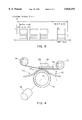
- FIG. 1 schematically shows the basic functions of a direct thermal printer
- FIG. 2 an electronic circuit according to the present invention for use with the printer illustrated in FIG. 1;
- FIG. 3 shows the activation pulses according to the present invention applied to a heating element of the circuit in FIG. 2;
- FIG. 4 schematically shows the basic functions of a direct thermal printer which uses a protective or a reductor-donor ribbon.
- FIG. 1 there is shown a global principle scheme of a thermal printing apparatus that can be used in accordance with the present invention.
- This apparatus is capable to print a line of pixels at a time on a recording material, further called “direct thermal imaging element” 3 or (shortly) “imaging element” 3, comprising on a support a thermosensitive layer comprising an organic silver salt, which generally is in the form of a sheet.
- the imaging element 3 is secured to a rotatable drum 15, driven by a drive mechanism (not shown) which continuously advances the drum 15 and the imaging element 3 past a stationary thermal print head 16. This head 16 presses the imaging element 3 against the drum 15 and receives the output of the driver circuits.
- the thermal print head 16 normally includes a plurality of heating elements equal in number to the number of pixels in the image data present in a line memory.
- the imagewise heating of the heating element is performed on a line by line basis, the "line” may be horizontal or vertical depending on the configuration of the printer, with the heating resistors geometrically juxtaposed each along another and with gradual construction of the output density.
- Each of these resistors is capable of being energised by heating pulses, the energy of which is controlled in accordance with the required density of the corresponding picture element.
- the output energy increases and so the optical density of the hardcopy image 17 on the imaging element 3.
- lower density image data cause the heating energy to be decreased, giving a lighter picture 17.
- a sensor 43 positioned adjacent the path of the imaging element, upstream of the print head 16, generates a signal indicative of the type of the recording material 11, e.g. being opaque or being transparant.
- a further sensor 44 positioned adjacent the path of the imaging element, downstream of the print head 16, generates a signal indicative of the quality of the printed image.
- the printer is capable of operating in at least two modes, including a standard operating mode in which the drive motor 18 is driven at a standard speed and a fast operating mode in which the drive motor 18 is driven at a relatively fast speed.
- a digital signal representation is obtained from an imaging device 40 in an "image acquisition apparatus” 21 (also described as “control means 21 for receiving image data”), for example from (see referral 40) an X-ray camera or from a graphic system.
- the image data includes not only picture data, but also additional alpha/numeric data related to the subject of the (e.g. X-ray) picture and indicative of technical information related to conditions under which the (e.g. X-ray) picture was taken, this additional data being supplied from a keyboard 45 or a remote control device 46.
- the image acquisition apparatus 21 serves to separate out picture data from the alpha/numeric data contained in the image data, such as by optical character recognition (often indicated by "OCR") of the alpha/numeric data.
- OCR optical character recognition
- the picture data signal is applied via a digital interface 22 and a first storage means (MEMORY) 23 to a data processor 24, which assigns a pulse width and number and the heating energy applied to a given heating element 28.
- the digital image signals are fed via a line buffer 33 to a parallel to serial converter 25 of which an advantageous embodiment is disclosed in European Patent Application EPA 91.201.608.6 (in the name of Agfa-Gevaert) to produce a stream of serial data of bits representing the next line of data to be printed which is passed to a second storage means in the form of a shift register 26. Thereafter, under controlled conditions, these data bits are supplied in parallel to the associated inputs of a latch register 27. Once the bits of data from the shift register 26 are stored in the latch register 27, another line of bits can be subsequently clocked into the shift register 26.
- the upper terminals 30 of the heating elements 28 are connected to a positive voltage source V, while the lower terminals 31 of the heating elements are respectively connected to the collectors of drive transistors 29, whose emitters are grounded. These transistors 29 are selectively turned on by a high state signal, indicated as an ANDed STROBE signal supplied on line 32 applied to the bases of the transistors 29 to allow energy to flow through the associated heating elements 28. In this way a direct thermal hardcopy 17 of the electrical image data is recorded.
- Automatic change-over means 41 mainly comprising a dedicated software program in addition to the above mentioned sensors and user preferences, are provided for switching the printer between the operating modes.
- the change-over means 41 receives signals from the imaging element material sensor 43 and from the output sensor 44.
- the change-over means 41 also receives alpha/numeric data separated from the image signal by the image acquisition apparatus 21.
- the change-over means 41 operates in response to signals included in the image data, to signals from sensor 43 and signals from sensor 44, to adjust the speed of the variable speed motor 18 and to change the criteria applied by the processing unit 24, in particular to change one or more of pulse width, pulse number and heating energy.
- the heating energy and the speed of the drive motor 18 are thereby controlled in accordance with print prerequisites.
- the repetition strobe period (t s ) consists of one heating cycle (t son ) and one cooling cycle (t s -t son ) as indicated in FIG. 3.
- the strobe pulse width (t son ) is the time during which an enable strobe signal is on.
- the strobe duty cycle of a heating element is the ratio of the pulse width (t son ) to the repetition strobe period (t s ).
- the line time (t 1 ) is divided by the number (N) of strobe pulses each with a repetition strobe period t s as indicated in FIG. 3.
- N the number of strobe pulses each with a repetition strobe period t s as indicated in FIG. 3.
- the maximum diffusion time would be reached after 1024 sequential strobe periods.
- a "third operating mode" may be introduced.
- the line time of the printing system is changed in accordance with a printing prerequisite. More specifically, if an increased addressability (or resolution) is prescribed, certain criteria applied by the processing unit 24 are changed, in particular so that the line time is decreased.
- the print head used in the printer according to the invention may take a number of different forms.
- the print head may comprise a thermal print head for image-wise heating the thermosensitive layer, comprising individually energisable juxtaposed heating elements.
- Thermal print heads that can be used are commercially available and include the Fujitsu Head FTP-040 MCS001, the TDK Thermal Head F415 HH7-1089 and the Rohm Thermal Head KE 2008-F3.
- line-type print heads having a one dimensional array have been referred to here, the present invention can also make use of two dimensionally arranged print head arrays.
- direct thermal printing mainly was directed towards a method of representing an image of the human body obtained during medical imaging and most particularly to a printer intended for printing medical image picture data received from a medical imaging device. More in particular, said image data may be medical image picture data received from a medical image camera 40.
- the image data may be graphical image picture data received from a computerized publishing system.
- image data may be in the form of screens representing graphical images for use in printing art.
- These screens can be obtained by computer Desk-Top Publishing systems, such as e.g. Ventura publisher (tradename).
- These systems combinate both text and pictures, retrieved from e.g. manual input in Word processors (e.g. Wordperfect; tradename), OCR, picture scanners and software used for image manipulation (e.g. Adobe Photoshop; tradename).
- Word processors e.g. Wordperfect; tradename
- OCR optical character scanners
- software used for image manipulation e.g. Adobe Photoshop; tradename
- direct thermal printing mainly comprises so-called monosheet imaging elements (indicated by referral 3 in FIG. 1).
- direct thermal printing also comprises a so-called “donor ribbon or donor element” -which may be “a protective ribbon” or which may be “a reduction ribbon”- (indicated by referral 2 in FIG. 4) and a so-called “receiving element” (indicated by referral 1 in FIG. 4).
- donor ribbon or donor element which may be “a protective ribbon” or which may be “a reduction ribbon”- (indicated by referral 2 in FIG. 4) and a so-called “receiving element” (indicated by referral 1 in FIG. 4).
- Direct thermal monosheet imaging elements are described in e.g. EPA-94.201.717.9 and EPA-94.201.954.8 (both in the name of Agfa-Gevaert) and in WO 94/16361 (in the name of Labelon Corp. U.S.A.).
- Direct thermal printing with a so called protective ribbon is described e.g. in EPA-92.204.008.4 (in the name of Agfa-Gevaert).
- Direct thermal printing with a so called reduction ribbon is described e.g. in EPA-92.200.612.3 (in the name of Agfa-Gevaert).
- FIG. 4 schematically shows the basic functions of a direct thermal printer which uses a reductor (donor) ribbon. As many elements of FIG. 4 are similar in structure and in operation to the correspondingly numbered structural elements described in relation to FIG. 1, a full description of FIG. 4 is not necessary here (in order to avoid duplication of explanation).
- Reduction ribbon printing uses a thermal print head 16, which can be a thick or a thin film thermal print head, to selectively heat specific portions of the donor element 2 in contact with a receiving element 1.
- Supply roller 13 and take-up roller 14 are driven by variable speed motor 18 with a predetermined tension in the web or ribbon of the donor element 2.
- a donor sensor 42 positioned adjacent the donor material path generates a signal indicative of the presence of a donor element 2.
- the sensor 42 is capable of distinguishing between a direct thermal printing system with a monosheet imaging element (as illustrated in FIG. 1) and a direct thermal printing system with both a donor element and a receiving element (as illustrated in FIG. 4).
- the change-over means 41 receives signals from the donor sensor 42, from the receiving element sensor 43 and from the output sensor 44, indicative respectively of the nature of the donor 2, of the nature of the receiving element 1 and of the quality of the printed image respectively.
- the change-over means 41 also receives alpha/numeric data separated from the image signal by the image acquisition apparatus 21.
- the change-over means 41 operates in response to predetermined quality signals included in the image data, the donor signal from the sensor 42, the receiving element material type from the sensor 43 and the printed image quality signals from the sensor 44, to adjust the speed of the variable speed motor 18 and to change the criteria applied by the processing unit 24, in particular to change one or more of pulse width, pulse number and heating energy.
- the heating energy and the speed of the drive motor 18 are thereby controlled in accordance with the predetermined print quality.
- imaging element 3 is a combination of a donor element 2 comprising on a support at least one donor layer comprising a thermotransferable reducing agent capable of reducing a silver compound (e.g. silver behenate) to metallic silver upon heating in face to face relationship with a receiving element 1 comprising on a support at least one receiving layer comprising at least one silver compound capable of being reduced by means of heat in the presence of a reducing agent.
- a thermotransferable reducing agent capable of reducing a silver compound (e.g. silver behenate) to metallic silver upon heating in face to face relationship
- a receiving element 1 comprising on a support at least one receiving layer comprising at least one silver compound capable of being reduced by means of heat in the presence of a reducing agent.
- a direct thermal printer comprises a print head 16; control means 21 for receiving image data; drive means for passing a donor element 2 comprising on a support a donor layer comprising a binder and a thermotransferable reducing agent capable of reducing a silver source (e.g.
- said printer is capable of operating in at least two modes, including a standard operating mode in which said drive motor 18 is driven at a standard speed and at least one fast operating mode in which said drive motor 18 is driven at a relatively fast speed, characterised by automatic change-over means 41 for switching said printer between said operating modes.
- said thermally reducible source of silver is an organic silver salt. More preferably, said organic silver salt is silver behenate.
- the present invention is equally applicable to thermal wax printing.
Abstract
Description
Claims (28)
Applications Claiming Priority (2)
| Application Number | Priority Date | Filing Date | Title |
|---|---|---|---|
| EP95200237A EP0724964B1 (en) | 1995-01-31 | 1995-01-31 | Direct thermal printing method and apparatus |
| EP95200237 | 1995-01-31 |
Publications (1)
| Publication Number | Publication Date |
|---|---|
| US5815191A true US5815191A (en) | 1998-09-29 |
Family
ID=8219985
Family Applications (1)
| Application Number | Title | Priority Date | Filing Date |
|---|---|---|---|
| US08/584,450 Expired - Lifetime US5815191A (en) | 1995-01-31 | 1996-01-11 | Direct thermal printing method and apparatus |
Country Status (4)
| Country | Link |
|---|---|
| US (1) | US5815191A (en) |
| EP (1) | EP0724964B1 (en) |
| JP (1) | JPH08276609A (en) |
| DE (1) | DE69504809T2 (en) |
Cited By (47)
| Publication number | Priority date | Publication date | Assignee | Title |
|---|---|---|---|---|
| US6148347A (en) * | 1996-11-20 | 2000-11-14 | Cisco Technology, Inc. | Mode selectable memory controller for PCMCIA standard memory cards and non-standard memory cards |
| US6148722A (en) * | 1998-06-08 | 2000-11-21 | Primera Technology, Inc. | Compact disc and recordable compact disc thermal transfer printer |
| US6302601B1 (en) | 1998-06-08 | 2001-10-16 | Primera Technology, Inc. | Substrate carrier and printhead mounting for printer |
| US6382852B1 (en) * | 1997-08-27 | 2002-05-07 | Sony Corporation | Information recording apparatus and method |
| US6435562B1 (en) * | 1999-11-30 | 2002-08-20 | Eastman Kodak Company | Method and apparatus for making an album page |
| US6447181B1 (en) | 1998-06-08 | 2002-09-10 | Primera Technology, Inc. | Variable position, force and velocity printer |
| US6759366B2 (en) | 2001-12-18 | 2004-07-06 | Ncr Corporation | Dual-sided imaging element |
| US20040135869A1 (en) * | 2002-12-17 | 2004-07-15 | Dirk Verdyck | Deconvolution scheme for reducing cross-talk during an in the line printing sequence |
| US6784906B2 (en) | 2001-12-18 | 2004-08-31 | Ncr Corporation | Direct thermal printer |
| US6856425B2 (en) * | 1996-12-06 | 2005-02-15 | Canon Kabushiki Kaisha | Image processing system, digital camera, and printing apparatus |
| US6891556B2 (en) * | 2001-03-23 | 2005-05-10 | Canon Kabushiki Kaisha | Image printing method and apparatus |
| US20060232642A1 (en) * | 2005-04-06 | 2006-10-19 | Zink Imaging, Llc | Multicolor thermal imaging method and thermal imaging member for use therein |
| US20060289633A1 (en) * | 2005-06-23 | 2006-12-28 | Ncr Corporation | Receipts having dual-sided thermal printing |
| US20070120943A1 (en) * | 2005-11-30 | 2007-05-31 | Ncr Corporation | Dual-sided thermal printing with labels |
| US20070120942A1 (en) * | 2005-11-30 | 2007-05-31 | Ncr Corporation | Dual-sided two color thermal printing |
| US20070134039A1 (en) * | 2005-12-08 | 2007-06-14 | Ncr Corporation | Dual-sided thermal printing |
| US20070206982A1 (en) * | 2006-03-01 | 2007-09-06 | Ncr Corporation | Thermal indicators |
| US20070207926A1 (en) * | 2006-03-03 | 2007-09-06 | Ncr Corporation | Two-sided thermal paper |
| US20070211094A1 (en) * | 2006-03-07 | 2007-09-13 | Ncr Corporation | Dual-sided thermal pharmacy script printing |
| US20070210572A1 (en) * | 2006-03-07 | 2007-09-13 | Ncr Corporation | Dual-sided thermal security features |
| US20070213214A1 (en) * | 2006-03-07 | 2007-09-13 | Roth Joseph D | Two-sided thermal wrap around label |
| US20070213213A1 (en) * | 2006-03-07 | 2007-09-13 | Ncr Corporation | UV and thermal guard |
| US20070211132A1 (en) * | 2006-03-07 | 2007-09-13 | Lyons Dale R | Two-sided thermal print configurations |
| US20070211135A1 (en) * | 2005-12-08 | 2007-09-13 | Richard Moreland | Dual-sided two-ply direct thermal image element |
| US20070211099A1 (en) * | 2006-03-07 | 2007-09-13 | Lyons Dale R | Two-sided thermal print sensing |
| US20070211134A1 (en) * | 2006-03-07 | 2007-09-13 | Ncr Corporation | Direct thermal and inkjet dual-sided printing |
| US20070212515A1 (en) * | 2006-03-07 | 2007-09-13 | Ncr Corporation | Dual-sided thermal form card |
| US20070213215A1 (en) * | 2006-03-07 | 2007-09-13 | Ncr Corporation | Multi-color dual-sided thermal printing |
| US20070212146A1 (en) * | 2005-12-08 | 2007-09-13 | Dale Lyons | Two-sided thermal print switch |
| US20070244005A1 (en) * | 2006-03-07 | 2007-10-18 | Ncr Corporation | Multisided thermal media combinations |
| US20080297583A1 (en) * | 2007-06-04 | 2008-12-04 | Dale Lyons | Two-sided thermal print command |
| US20080316534A1 (en) * | 2007-06-20 | 2008-12-25 | Mcgarry Colman | Two-sided print data splitting |
| US20090015647A1 (en) * | 2007-07-12 | 2009-01-15 | Rawlings Timothy W | Two-side thermal printer |
| US20090017237A1 (en) * | 2007-07-12 | 2009-01-15 | Rawlings Timothy W | Two-sided thermal transfer ribbon |
| US20090058892A1 (en) * | 2007-08-31 | 2009-03-05 | Ncr Corporation | Direct thermal and inkjet dual-sided printing |
| US20090060606A1 (en) * | 2007-08-31 | 2009-03-05 | Ncr Corporation | Controlled fold document delivery |
| US20090089172A1 (en) * | 2007-09-28 | 2009-04-02 | Quinlan Mark D | Multi-lingual two-sided printing |
| US20090199527A1 (en) * | 2008-02-13 | 2009-08-13 | Mary Ann Wehr | Fanfold media dust inhibitor |
| US7589752B2 (en) | 2005-01-15 | 2009-09-15 | Ncr Corporation | Two-sided thermal printing |
| WO2010118549A1 (en) * | 2009-04-13 | 2010-10-21 | 青岛尤尼科技有限公司 | Printer, method of enlarging printing size and printing system |
| US7839425B2 (en) | 2008-09-17 | 2010-11-23 | Ncr Corporation | Method of controlling thermal printing |
| US8211826B2 (en) | 2007-07-12 | 2012-07-03 | Ncr Corporation | Two-sided thermal media |
| US8462184B2 (en) | 2005-12-08 | 2013-06-11 | Ncr Corporation | Two-sided thermal printer control |
| US20140009768A1 (en) * | 2012-01-05 | 2014-01-09 | Zih Corp. | Method and apparatus for printhead control |
| US8848010B2 (en) | 2007-07-12 | 2014-09-30 | Ncr Corporation | Selective direct thermal and thermal transfer printing |
| US9370939B2 (en) | 2012-01-05 | 2016-06-21 | Zih Corp. | Method and apparatus for printer control |
| US9975368B2 (en) | 2008-02-13 | 2018-05-22 | Iconex Llc | Fanfold media dust inhibitor |
Families Citing this family (5)
| Publication number | Priority date | Publication date | Assignee | Title |
|---|---|---|---|---|
| US6081089A (en) * | 1997-05-01 | 2000-06-27 | Agfa-Gevaert N.V. | Drive system |
| EP0903844B1 (en) * | 1997-09-23 | 2004-12-08 | Agfa-Gevaert | Drive system |
| EP1104700B1 (en) | 1999-12-01 | 2005-10-12 | Agfa-Gevaert | Thermal printhead |
| JP2001246772A (en) * | 2000-03-07 | 2001-09-11 | Alps Electric Co Ltd | Image forming apparatus |
| EP1234677B1 (en) | 2001-01-25 | 2004-06-09 | Agfa-Gevaert | Method for thermal printing |
Citations (5)
| Publication number | Priority date | Publication date | Assignee | Title |
|---|---|---|---|---|
| US4843409A (en) * | 1986-07-22 | 1989-06-27 | Konishiroku Photo Industry Co., Ltd. | Thermal transfer printer |
| JPH0538839A (en) * | 1991-08-08 | 1993-02-19 | Ricoh Co Ltd | Thermal printer |
| US5191356A (en) * | 1986-07-18 | 1993-03-02 | Canon Kabushiki Kaisha | Tower conserving recording apparatus |
| US5488223A (en) * | 1994-09-13 | 1996-01-30 | Intermec Corporation | System and method for automatic selection of printer control parameters |
| US5564841A (en) * | 1994-09-13 | 1996-10-15 | Intermec Corporation | System and method for dynamic adjustment of bar code printer parameters |
Family Cites Families (4)
| Publication number | Priority date | Publication date | Assignee | Title |
|---|---|---|---|---|
| JPS59145161A (en) * | 1983-02-08 | 1984-08-20 | Hitachi Ltd | Thermal transfer printer |
| JPS61108588A (en) * | 1984-11-01 | 1986-05-27 | Hitachi Ltd | System for controlling feed of recording paper |
| US4578689A (en) * | 1984-11-26 | 1986-03-25 | Data Recording Systems, Inc. | Dual mode laser printer |
| EP0622217B1 (en) * | 1993-04-27 | 1997-01-02 | Agfa-Gevaert N.V. | Method for making an image using a direct thermal imaging element |
-
1995
- 1995-01-31 EP EP95200237A patent/EP0724964B1/en not_active Expired - Lifetime
- 1995-01-31 DE DE69504809T patent/DE69504809T2/en not_active Expired - Lifetime
-
1996
- 1996-01-11 US US08/584,450 patent/US5815191A/en not_active Expired - Lifetime
- 1996-01-22 JP JP8028420A patent/JPH08276609A/en active Pending
Patent Citations (5)
| Publication number | Priority date | Publication date | Assignee | Title |
|---|---|---|---|---|
| US5191356A (en) * | 1986-07-18 | 1993-03-02 | Canon Kabushiki Kaisha | Tower conserving recording apparatus |
| US4843409A (en) * | 1986-07-22 | 1989-06-27 | Konishiroku Photo Industry Co., Ltd. | Thermal transfer printer |
| JPH0538839A (en) * | 1991-08-08 | 1993-02-19 | Ricoh Co Ltd | Thermal printer |
| US5488223A (en) * | 1994-09-13 | 1996-01-30 | Intermec Corporation | System and method for automatic selection of printer control parameters |
| US5564841A (en) * | 1994-09-13 | 1996-10-15 | Intermec Corporation | System and method for dynamic adjustment of bar code printer parameters |
Cited By (83)
| Publication number | Priority date | Publication date | Assignee | Title |
|---|---|---|---|---|
| US6148347A (en) * | 1996-11-20 | 2000-11-14 | Cisco Technology, Inc. | Mode selectable memory controller for PCMCIA standard memory cards and non-standard memory cards |
| US6856425B2 (en) * | 1996-12-06 | 2005-02-15 | Canon Kabushiki Kaisha | Image processing system, digital camera, and printing apparatus |
| US6382852B1 (en) * | 1997-08-27 | 2002-05-07 | Sony Corporation | Information recording apparatus and method |
| US6148722A (en) * | 1998-06-08 | 2000-11-21 | Primera Technology, Inc. | Compact disc and recordable compact disc thermal transfer printer |
| US6302601B1 (en) | 1998-06-08 | 2001-10-16 | Primera Technology, Inc. | Substrate carrier and printhead mounting for printer |
| US6447181B1 (en) | 1998-06-08 | 2002-09-10 | Primera Technology, Inc. | Variable position, force and velocity printer |
| US6435562B1 (en) * | 1999-11-30 | 2002-08-20 | Eastman Kodak Company | Method and apparatus for making an album page |
| US6891556B2 (en) * | 2001-03-23 | 2005-05-10 | Canon Kabushiki Kaisha | Image printing method and apparatus |
| US6784906B2 (en) | 2001-12-18 | 2004-08-31 | Ncr Corporation | Direct thermal printer |
| US6759366B2 (en) | 2001-12-18 | 2004-07-06 | Ncr Corporation | Dual-sided imaging element |
| US7023461B2 (en) * | 2002-12-17 | 2006-04-04 | Agfa-Gevaert | Deconvolution scheme for reducing cross-talk during an in the line printing sequence |
| US20040135869A1 (en) * | 2002-12-17 | 2004-07-15 | Dirk Verdyck | Deconvolution scheme for reducing cross-talk during an in the line printing sequence |
| US7589752B2 (en) | 2005-01-15 | 2009-09-15 | Ncr Corporation | Two-sided thermal printing |
| US8068126B2 (en) | 2005-04-06 | 2011-11-29 | Zink Imaging, Inc. | Multicolor thermal imaging method and thermal printer |
| US20060232642A1 (en) * | 2005-04-06 | 2006-10-19 | Zink Imaging, Llc | Multicolor thermal imaging method and thermal imaging member for use therein |
| US20090096833A1 (en) * | 2005-04-06 | 2009-04-16 | Busch Brian D | Multicolor thermal imaging method and thermal imaging member for use therein |
| US20080266373A1 (en) * | 2005-04-06 | 2008-10-30 | Zink Imaging, Llc | Multicolor thermal imaging method and thermal printer |
| US8502848B2 (en) | 2005-04-06 | 2013-08-06 | Zink Imaging, Inc. | Multicolor thermal imaging method and thermal printer |
| US7768540B2 (en) | 2005-04-06 | 2010-08-03 | Zink Imaging, Inc. | Multicolor thermal imaging method and thermal printer |
| US7820370B2 (en) | 2005-04-06 | 2010-10-26 | Zink Imaging, Inc. | Multicolor thermal imaging method and thermal imaging member for use therein |
| US20060289633A1 (en) * | 2005-06-23 | 2006-12-28 | Ncr Corporation | Receipts having dual-sided thermal printing |
| US20070120943A1 (en) * | 2005-11-30 | 2007-05-31 | Ncr Corporation | Dual-sided thermal printing with labels |
| US20070120942A1 (en) * | 2005-11-30 | 2007-05-31 | Ncr Corporation | Dual-sided two color thermal printing |
| US20070134039A1 (en) * | 2005-12-08 | 2007-06-14 | Ncr Corporation | Dual-sided thermal printing |
| US20070211135A1 (en) * | 2005-12-08 | 2007-09-13 | Richard Moreland | Dual-sided two-ply direct thermal image element |
| US7777770B2 (en) | 2005-12-08 | 2010-08-17 | Ncr Corporation | Dual-sided two-ply direct thermal image element |
| US8462184B2 (en) | 2005-12-08 | 2013-06-11 | Ncr Corporation | Two-sided thermal printer control |
| US20070212146A1 (en) * | 2005-12-08 | 2007-09-13 | Dale Lyons | Two-sided thermal print switch |
| US20090290923A9 (en) * | 2005-12-08 | 2009-11-26 | Dale Lyons | Two-sided thermal print switch |
| US8721202B2 (en) | 2005-12-08 | 2014-05-13 | Ncr Corporation | Two-sided thermal print switch |
| US8083423B2 (en) | 2006-03-01 | 2011-12-27 | Ncr Corporation | Thermal indicators |
| US20070206982A1 (en) * | 2006-03-01 | 2007-09-06 | Ncr Corporation | Thermal indicators |
| US8114812B2 (en) | 2006-03-03 | 2012-02-14 | Ncr Corporation | Two-sided thermal paper |
| US20070207926A1 (en) * | 2006-03-03 | 2007-09-06 | Ncr Corporation | Two-sided thermal paper |
| US20090163363A1 (en) * | 2006-03-07 | 2009-06-25 | Richard Moreland | Dual-sided two-ply direct thermal image element |
| US20070213213A1 (en) * | 2006-03-07 | 2007-09-13 | Ncr Corporation | UV and thermal guard |
| US9024986B2 (en) | 2006-03-07 | 2015-05-05 | Ncr Corporation | Dual-sided thermal pharmacy script printing |
| US20070211094A1 (en) * | 2006-03-07 | 2007-09-13 | Ncr Corporation | Dual-sided thermal pharmacy script printing |
| US8670009B2 (en) | 2006-03-07 | 2014-03-11 | Ncr Corporation | Two-sided thermal print sensing |
| US20070210572A1 (en) * | 2006-03-07 | 2007-09-13 | Ncr Corporation | Dual-sided thermal security features |
| US20070213214A1 (en) * | 2006-03-07 | 2007-09-13 | Roth Joseph D | Two-sided thermal wrap around label |
| US8367580B2 (en) | 2006-03-07 | 2013-02-05 | Ncr Corporation | Dual-sided thermal security features |
| US20090185021A9 (en) * | 2006-03-07 | 2009-07-23 | Lyons Dale R | Two-sided thermal print configurations |
| US8252717B2 (en) | 2006-03-07 | 2012-08-28 | Ncr Corporation | Dual-sided two-ply direct thermal image element |
| US8222184B2 (en) | 2006-03-07 | 2012-07-17 | Ncr Corporation | UV and thermal guard |
| US20070244005A1 (en) * | 2006-03-07 | 2007-10-18 | Ncr Corporation | Multisided thermal media combinations |
| US7710442B2 (en) | 2006-03-07 | 2010-05-04 | Ncr Corporation | Two-sided thermal print configurations |
| US7764299B2 (en) | 2006-03-07 | 2010-07-27 | Ncr Corporation | Direct thermal and inkjet dual-sided printing |
| US20070213215A1 (en) * | 2006-03-07 | 2007-09-13 | Ncr Corporation | Multi-color dual-sided thermal printing |
| US20070212515A1 (en) * | 2006-03-07 | 2007-09-13 | Ncr Corporation | Dual-sided thermal form card |
| US20100253716A1 (en) * | 2006-03-07 | 2010-10-07 | Ncr Corporation | Direct thermal and inkjet dual-sided printing |
| US8173575B2 (en) | 2006-03-07 | 2012-05-08 | Ncr Corporation | Dual-sided thermal form card |
| US20070211134A1 (en) * | 2006-03-07 | 2007-09-13 | Ncr Corporation | Direct thermal and inkjet dual-sided printing |
| US20070211132A1 (en) * | 2006-03-07 | 2007-09-13 | Lyons Dale R | Two-sided thermal print configurations |
| US20070211099A1 (en) * | 2006-03-07 | 2007-09-13 | Lyons Dale R | Two-sided thermal print sensing |
| US8043993B2 (en) | 2006-03-07 | 2011-10-25 | Ncr Corporation | Two-sided thermal wrap around label |
| US8067335B2 (en) | 2006-03-07 | 2011-11-29 | Ncr Corporation | Multisided thermal media combinations |
| US8194107B2 (en) | 2007-06-04 | 2012-06-05 | Ncr Corporation | Two-sided thermal print command |
| US20080297583A1 (en) * | 2007-06-04 | 2008-12-04 | Dale Lyons | Two-sided thermal print command |
| US8576436B2 (en) | 2007-06-20 | 2013-11-05 | Ncr Corporation | Two-sided print data splitting |
| US20080316534A1 (en) * | 2007-06-20 | 2008-12-25 | Mcgarry Colman | Two-sided print data splitting |
| US20090015647A1 (en) * | 2007-07-12 | 2009-01-15 | Rawlings Timothy W | Two-side thermal printer |
| US20090017237A1 (en) * | 2007-07-12 | 2009-01-15 | Rawlings Timothy W | Two-sided thermal transfer ribbon |
| US8211826B2 (en) | 2007-07-12 | 2012-07-03 | Ncr Corporation | Two-sided thermal media |
| US9056488B2 (en) | 2007-07-12 | 2015-06-16 | Ncr Corporation | Two-side thermal printer |
| US8848010B2 (en) | 2007-07-12 | 2014-09-30 | Ncr Corporation | Selective direct thermal and thermal transfer printing |
| US7531224B2 (en) | 2007-07-12 | 2009-05-12 | Ncr Corporation | Two-sided thermal transfer ribbon |
| US20090058892A1 (en) * | 2007-08-31 | 2009-03-05 | Ncr Corporation | Direct thermal and inkjet dual-sided printing |
| US8182161B2 (en) | 2007-08-31 | 2012-05-22 | Ncr Corporation | Controlled fold document delivery |
| US20090060606A1 (en) * | 2007-08-31 | 2009-03-05 | Ncr Corporation | Controlled fold document delivery |
| US20090089172A1 (en) * | 2007-09-28 | 2009-04-02 | Quinlan Mark D | Multi-lingual two-sided printing |
| US8504427B2 (en) | 2007-09-28 | 2013-08-06 | Ncr Corporation | Multi-lingual two-sided printing |
| US8707898B2 (en) * | 2008-02-13 | 2014-04-29 | Ncr Corporation | Apparatus for fanfolding media |
| US20090199527A1 (en) * | 2008-02-13 | 2009-08-13 | Mary Ann Wehr | Fanfold media dust inhibitor |
| US9975368B2 (en) | 2008-02-13 | 2018-05-22 | Iconex Llc | Fanfold media dust inhibitor |
| US8314821B2 (en) | 2008-09-17 | 2012-11-20 | Ncr Corporation | Method of controlling thermal printing |
| US7839425B2 (en) | 2008-09-17 | 2010-11-23 | Ncr Corporation | Method of controlling thermal printing |
| US20110063394A1 (en) * | 2008-09-17 | 2011-03-17 | Morrison Randall L | Method of controlling thermal printing |
| WO2010118549A1 (en) * | 2009-04-13 | 2010-10-21 | 青岛尤尼科技有限公司 | Printer, method of enlarging printing size and printing system |
| US20140009768A1 (en) * | 2012-01-05 | 2014-01-09 | Zih Corp. | Method and apparatus for printhead control |
| US9168759B2 (en) * | 2012-01-05 | 2015-10-27 | Zih Corp. | Method and apparatus for printhead control |
| US9370939B2 (en) | 2012-01-05 | 2016-06-21 | Zih Corp. | Method and apparatus for printer control |
| US9925796B2 (en) | 2012-01-05 | 2018-03-27 | Zih Corp. | Method and apparatus for printhead control |
Also Published As
| Publication number | Publication date |
|---|---|
| JPH08276609A (en) | 1996-10-22 |
| DE69504809T2 (en) | 1999-05-12 |
| EP0724964A1 (en) | 1996-08-07 |
| DE69504809D1 (en) | 1998-10-22 |
| EP0724964B1 (en) | 1998-09-16 |
Similar Documents
| Publication | Publication Date | Title |
|---|---|---|
| US5815191A (en) | Direct thermal printing method and apparatus | |
| US3952311A (en) | Electro-optical printing system | |
| JPH07503421A (en) | Method and apparatus for controlling a thermal print head | |
| US5105206A (en) | Thermal printer for producing transparencies | |
| US4835551A (en) | Optical recorder with plural resolution recording | |
| US5327165A (en) | Electronic printing system for imaging thermally sensitive paper | |
| EP0654355A1 (en) | Method for making an image by direct thermal imaging | |
| US4590484A (en) | Thermal recording head driving control system | |
| EP0193342B1 (en) | Thermal printer | |
| JPH0813546B2 (en) | Color thermal recording method | |
| EP0529532A2 (en) | Method and apparatus for the calibration of a multichannel printer | |
| US6475709B2 (en) | Method for thermal recording | |
| EP0193343B1 (en) | Thermal printer | |
| EP1104699B1 (en) | Method and apparatus for thermal recording | |
| EP0724963A1 (en) | Thermal dye diffusion printer and method for its use | |
| GB2190817A (en) | Thermal image recording apparatus | |
| JPS63202473A (en) | Thermal recorder corresponding to plural kinds of subscanning line density | |
| US5453766A (en) | Method for implementing specific transfer curves in thermal sublimation printers | |
| JP3174197B2 (en) | Image recording method | |
| KR100743793B1 (en) | Thermosensitive recording device | |
| US5434596A (en) | Quarter-tone thermal backprinting | |
| JPS6256076A (en) | Color printer | |
| JP3154589B2 (en) | Color thermal printer | |
| JPS572775A (en) | Recording system for gradation image | |
| JPH08118704A (en) | Thermorecording apparatus |
Legal Events
| Date | Code | Title | Description |
|---|---|---|---|
| AS | Assignment |
Owner name: AGFA-GEVAERT, BELGIUM Free format text: ASSIGNMENT OF ASSIGNORS INTEREST;ASSIGNORS:MICHIELSEN, JOSEPH;OELBRANDT, LEO;TILEMANS, DAVID;AND OTHERS;REEL/FRAME:007847/0207 Effective date: 19951205 |
|
| STCF | Information on status: patent grant |
Free format text: PATENTED CASE |
|
| CC | Certificate of correction | ||
| FEPP | Fee payment procedure |
Free format text: PAYOR NUMBER ASSIGNED (ORIGINAL EVENT CODE: ASPN); ENTITY STATUS OF PATENT OWNER: LARGE ENTITY |
|
| FEPP | Fee payment procedure |
Free format text: PAYOR NUMBER ASSIGNED (ORIGINAL EVENT CODE: ASPN); ENTITY STATUS OF PATENT OWNER: LARGE ENTITY Free format text: PAYER NUMBER DE-ASSIGNED (ORIGINAL EVENT CODE: RMPN); ENTITY STATUS OF PATENT OWNER: LARGE ENTITY |
|
| FPAY | Fee payment |
Year of fee payment: 4 |
|
| REMI | Maintenance fee reminder mailed | ||
| FPAY | Fee payment |
Year of fee payment: 8 |
|
| AS | Assignment |
Owner name: AGFA HEALTHCARE N.V., BELGIUM Free format text: ASSIGNMENT OF ASSIGNORS INTEREST;ASSIGNOR:AGFA-GEVAERT N.V.;REEL/FRAME:020254/0713 Effective date: 20071108 |
|
| FPAY | Fee payment |
Year of fee payment: 12 |