US5816591A - Refuse container - Google Patents
Refuse container Download PDFInfo
- Publication number
- US5816591A US5816591A US08/593,836 US59383696A US5816591A US 5816591 A US5816591 A US 5816591A US 59383696 A US59383696 A US 59383696A US 5816591 A US5816591 A US 5816591A
- Authority
- US
- United States
- Prior art keywords
- brace
- storage bin
- wheel
- container according
- extending
- Prior art date
- Legal status (The legal status is an assumption and is not a legal conclusion. Google has not performed a legal analysis and makes no representation as to the accuracy of the status listed.)
- Expired - Fee Related
Links
Images
Classifications
-
- B—PERFORMING OPERATIONS; TRANSPORTING
- B65—CONVEYING; PACKING; STORING; HANDLING THIN OR FILAMENTARY MATERIAL
- B65F—GATHERING OR REMOVAL OF DOMESTIC OR LIKE REFUSE
- B65F1/00—Refuse receptacles; Accessories therefor
- B65F1/14—Other constructional features; Accessories
- B65F1/1468—Means for facilitating the transport of the receptacle, e.g. wheels, rolls
-
- Y—GENERAL TAGGING OF NEW TECHNOLOGICAL DEVELOPMENTS; GENERAL TAGGING OF CROSS-SECTIONAL TECHNOLOGIES SPANNING OVER SEVERAL SECTIONS OF THE IPC; TECHNICAL SUBJECTS COVERED BY FORMER USPC CROSS-REFERENCE ART COLLECTIONS [XRACs] AND DIGESTS
- Y10—TECHNICAL SUBJECTS COVERED BY FORMER USPC
- Y10S—TECHNICAL SUBJECTS COVERED BY FORMER USPC CROSS-REFERENCE ART COLLECTIONS [XRACs] AND DIGESTS
- Y10S220/00—Receptacles
- Y10S220/908—Trash container
Definitions
- This invention relates to a refuse container, and, more particularly, to a refuse container having a reinforced base and attached wheels for easy movement.
- Refuse containers have typically comprised a large cylindrically- or rectangularly-shaped storage bin with an attached axle carrying two rear wheels which allow the refuse container to be filled with waste material, tipped on the rear wheels and rolled to a desired disposal location. These carts have often been used to move large amounts of paper for recycling purposes.
- a relatively large refuse container of this type may be filled with stacks of paper which often weigh more than 300 pounds.
- containers of this type are often difficult to tip and control on their rear wheels.
- the floor of the container is often too weak to support the loads imparted such that the floor tends to buckle or collapse under heavy loading.
- U.S. Pat. No. 5,261,562 to Prout et al. discloses a refuse container having a caster wheel installed in the bottom of the container adjacent to the front wall of the container as the caster wheel permits the container to be rolled without tilting the container on its rear wheels.
- U.S. Pat. No. 5,235,795 to DeBusk discloses a lidded receptacle provided with depressions in the bottom thereof which define four wheel wells, each adapted to receive therein an axle for a fixed-direction wheel. Whereas the axles of the wheels of the depicted receptacle are fixed, DeBusk discloses that caster-type wheels may also be employed.
- U.S. Pat. No. 3,366,397 to Zeilstra et al. discloses a rubbish-carrying hand cart having a bottom equipped with metal reinforcing skids which are disposed in slightly diverging directions and are each bent upwardly at their forward ends.
- the skids are designed to resist abrasion of the bottom of the cart, assume the brunt of the cart load when the cart is standing in an upright position, and to prevent wear when the cart is slid along the ground in an upright position.
- U.S. Pat. No. 1,141,846 to Spremulli et al. discloses a garbage can which is provided with a convex bottom wall.
- a reinforcing stand consisting of a concave body plate and integral supporting legs is adapted to receive the can so that the bottom wall of the can is spaced from the ground.
- a refuse container comprises a walled storage bin having substantially vertical walls extending upwardly from a bottom wall, a wheel-bearing axle mounted to the lower rear portion of the storage bin to support the rear portion of the storage bin above the floor, and at least one wheel mounted to a front portion of the storage bin.
- a brace is disposed beneath the bottom wall and extends forwardly from the axle to the one or more wheels mounted on the front portion of the storage bin.
- the brace is mounted to the axle and the one or more front wheels mounted to the brace.
- the brace is mounted to the storage bin at the front portion of the bottom wall.
- the brace is mounted to the storage bin at the front portion of the bottom wall and fasteners mount a wheel mounting to the brace and mount the brace to the storage bin.
- the brace includes an upwardly extending central portion to resist downward deflection of the brace due to the weight of a load in the storage bin.
- at least one wheel is a caster wheel.
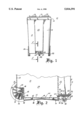
- FIG. 1 is a front elevational view of a refuse container according to the invention.
- FIG. 2 is a fragmentary cross-sectional view of the refuse container along the lines 2--2 of FIG. 1.
- a refuse container shown generally at 10 comprises a walled storage bin 12 formed of substantially ventrically extending walls 13 and a bottom wall 15 having rigid upper lip portion 14, hinged lid 16, handles 18, 20, and an indentation 22.
- the storage bin 12 is constructed of a rigid plastic material and can be of any conventional cylindrical or parallelepiped shape.
- Rigid upper lip portion 14 provides a brim for the closure of lid 16 and increases the strength of the storage bin 12.
- Handles 18, 20 are disposed along the rear edge of upper lip portion 14 and enable a user to firmly grip the handles for pushing the container.
- Indentation 22 comprises a vertically-disposed longitudinal recess which provides greater lateral support for the walls of storage bin 12 and which can optionally mount a lifting handle (not shown) for manually dumping the refuse container 10.
- the lower portion of storage bin 12 includes rear wheels 26, front wheel 28 and brace 30 which are illustrated in greater detail in FIG. 2.
- the storage bin wall 12 defines interior chamber 24 which houses the material to be disposed of.
- Rear wheels 26 are rotatably attached to axle 32 which is mounted to storage bin 12 through a pair of depending flanges 34 with axle openings 35.
- Brace 30 comprises a front flange 36, a rear flange 42 and an inverted V-shaped medial portion 48.
- the front flange 36 comprises a horizontally-extending wall 37 terminating at a downwardly extending vertical wall 38 at its rearward edge 40.
- Rear flange 42 includes a hook portion 44 and a downwardly and forwardly extending portion 46.
- the hook portion 44 includes a downwardly- and rearwardly-extending foot plate 45 which can serve as a foot rest for an operator while tipping the refuse container 10.
- the inverted V-shaped medial portion 48 comprises first and second angular walls 50 and 52 which converge at a crown point 54.
- the distal edges 56, 58 of angular walls 50, 52 extend to the lower edges of vertical wall 38 and angular wall 46, respectively.
- Front wheel 28 is mounted to the horizontally extending wall 37 of front flange 36 by threaded fasteners 64 or any other conventional fasteners.
- the vertical wall 38 of the front flange 36 is mounted to the bottom wall 15 of the storage bin 12 by a horizontally-extending threaded fastener 65 or any other suitable fastener.
- Front wheel 28 can be a conventional caster wheel which includes a mounting plate and a wheel which are rotatable about a vertical axis. In addition, several wheels may be mounted along the front portion of the brace to allow for greater support and steering control.
- the brace 30 provides additional support and reinforcement to the floor of storage bin 12. As a heavy load is placed in the interior chamber 24, the central floor portion 60 of the storage bin wall 12 tends to buckle and bow downwardly. However, the central floor portion 60 will contact crown portion 54 of brace 30 such that the brace 30 will help absorb the load in interior chamber 24 and prevent further downward deflection of the central floor portion 60 and possible failure of the floor of the storage bin wall altogether.
- the brace 30 further provides a secure mounting situs for the caster wheel 28. Frequently, the plastic bottom does not have sufficient strength to withstand the stresses of a front caster wheel, especially when the container is heavily loaded. The brace is rigid enough and strong enough to absorb these stresses.
Abstract
Description
Claims (12)
Priority Applications (1)
| Application Number | Priority Date | Filing Date | Title |
|---|---|---|---|
| US08/593,836 US5816591A (en) | 1996-01-30 | 1996-01-30 | Refuse container |
Applications Claiming Priority (1)
| Application Number | Priority Date | Filing Date | Title |
|---|---|---|---|
| US08/593,836 US5816591A (en) | 1996-01-30 | 1996-01-30 | Refuse container |
Publications (1)
| Publication Number | Publication Date |
|---|---|
| US5816591A true US5816591A (en) | 1998-10-06 |
Family
ID=24376397
Family Applications (1)
| Application Number | Title | Priority Date | Filing Date |
|---|---|---|---|
| US08/593,836 Expired - Fee Related US5816591A (en) | 1996-01-30 | 1996-01-30 | Refuse container |
Country Status (1)
| Country | Link |
|---|---|
| US (1) | US5816591A (en) |
Cited By (20)
| Publication number | Priority date | Publication date | Assignee | Title |
|---|---|---|---|---|
| US6276557B1 (en) * | 1999-04-08 | 2001-08-21 | Cascade Engineering, Inc. | Waste container with reinforced bottom |
| US6328320B1 (en) * | 1999-04-21 | 2001-12-11 | Cascade Engineering, Inc. | Waste container and axle assembly therefor |
| US6651673B2 (en) * | 1999-12-11 | 2003-11-25 | Hauni Maschinenbau Ag | Collecting receptacle for use in tobacco-processing machines |
| US20060045680A1 (en) * | 2004-04-12 | 2006-03-02 | American Container And Recycling, Incorporated | Method, apparatus and system for manufacturing containers, such as rotationally-molded noise-dampening containers |
| US20070045974A1 (en) * | 2005-08-24 | 2007-03-01 | Young Roger L | Wheeled can for bar refuse |
| EP1918222A1 (en) * | 2006-11-06 | 2008-05-07 | Environmental Solutions Europe B.V. | Refuse receptacle to be emptied by a side-loader |
| US20080246239A1 (en) * | 2007-04-05 | 2008-10-09 | Pat Connor | Secure accumulation/disposal bin |
| US7575246B1 (en) * | 2007-07-26 | 2009-08-18 | Lunski John G | Container wheel attachment system |
| US20090289067A1 (en) * | 2006-10-16 | 2009-11-26 | Baptiste George H | Trash Container with Retractable Weatherproof Cover |
| USD611218S1 (en) | 2007-04-05 | 2010-03-02 | Jake's Holding Corporation | Lid |
| US20120032409A1 (en) * | 2010-08-06 | 2012-02-09 | Robert Devine | Utility truck base reinforcement and method of manufacture |
| US8490240B1 (en) | 2012-09-06 | 2013-07-23 | John T. Mackesy | Attachable debris guide for waste bin |
| US8833593B2 (en) | 2008-05-30 | 2014-09-16 | Orbis Canada Limited | Residential recycling bin |
| US8881930B2 (en) | 2012-07-25 | 2014-11-11 | Orbis Corporation | Refuse container |
| US9096097B2 (en) | 2011-12-02 | 2015-08-04 | Toter, Llc | Wheel assembly |
| US9376255B2 (en) | 2013-02-22 | 2016-06-28 | Orbis Corporation | Waste container with gravity latch |
| US9828177B2 (en) | 2013-02-22 | 2017-11-28 | Orbis Corporation | Waste container with gravity latch and latch deactivation system |
| GB2560346A (en) * | 2017-03-08 | 2018-09-12 | David Orourke | A wheelie bin |
| DE202017106930U1 (en) * | 2017-11-15 | 2018-11-16 | Ese World B.V. | waste containers |
| US10273082B2 (en) * | 2017-06-30 | 2019-04-30 | Peter Alden LOUNSBURY | Attachable stabilizer for laterally supporting a garbage bin |
Citations (21)
| Publication number | Priority date | Publication date | Assignee | Title |
|---|---|---|---|---|
| US1141846A (en) * | 1915-04-14 | 1915-06-01 | Anthony Marcello Costa | Garrage-can. |
| US1542327A (en) * | 1924-06-14 | 1925-06-16 | Harry C Slingsby | Hand truck |
| US2382989A (en) * | 1944-07-03 | 1945-08-21 | Philo G Gilbert | Attachment for hand trucks |
| US2699339A (en) * | 1950-10-07 | 1955-01-11 | Stewart Warner Corp | Dolly with retractible wheel mounting |
| US3346271A (en) * | 1965-07-06 | 1967-10-10 | Fred E Parsons | Nestable cart of molded material |
| US3366397A (en) * | 1966-05-09 | 1968-01-30 | Charles F. Zeilstra | Rubbish carrying hand cart |
| US3399903A (en) * | 1967-08-08 | 1968-09-03 | Charles R. Bailey | Portable holder for refuse cans |
| US4040638A (en) * | 1976-05-03 | 1977-08-09 | Flagg Raymond C | Refuse collecting and conveying vehicle |
| US4420168A (en) * | 1982-06-10 | 1983-12-13 | Terra Bella Industries | Device for handling refuse or the like material |
| US4799699A (en) * | 1987-05-06 | 1989-01-24 | Shop-Vac Corporation | Dolly frame |
| US4836394A (en) * | 1988-05-09 | 1989-06-06 | The Heil Co. | Refuse container with two-position lid |
| US4930649A (en) * | 1989-08-18 | 1990-06-05 | North American Roto-Molding Corp. | Refuse container with molded hinge |
| US5088750A (en) * | 1990-04-30 | 1992-02-18 | Otto Industries, Inc. | Multi-functional waste container |
| US5131670A (en) * | 1990-12-28 | 1992-07-21 | Scubagear Inc. | Detachable scuba tank overland transport device |
| US5141124A (en) * | 1990-04-09 | 1992-08-25 | The Heil Co. | Refuse container with snap-on cover |
| US5165564A (en) * | 1992-01-14 | 1992-11-24 | Prout J Timothy | Refuse container with double wall lid |
| US5178244A (en) * | 1991-07-03 | 1993-01-12 | Joseph Liang | Luggage with unitarily pivoting front wheel assembly |
| US5230525A (en) * | 1991-06-25 | 1993-07-27 | Rubbermaid Commercial Products Inc. | Step-on waste container |
| US5235795A (en) * | 1990-05-09 | 1993-08-17 | Deroyal Industries, Inc. | System for the delivery, storage and disposal of medical supplies |
| US5261562A (en) * | 1992-01-14 | 1993-11-16 | Toter, Inc. | Blow-molded container with blow-molded handle |
| US5294137A (en) * | 1992-04-20 | 1994-03-15 | Hoover Group, Inc. | Transport container with integral dolly |
-
1996
- 1996-01-30 US US08/593,836 patent/US5816591A/en not_active Expired - Fee Related
Patent Citations (21)
| Publication number | Priority date | Publication date | Assignee | Title |
|---|---|---|---|---|
| US1141846A (en) * | 1915-04-14 | 1915-06-01 | Anthony Marcello Costa | Garrage-can. |
| US1542327A (en) * | 1924-06-14 | 1925-06-16 | Harry C Slingsby | Hand truck |
| US2382989A (en) * | 1944-07-03 | 1945-08-21 | Philo G Gilbert | Attachment for hand trucks |
| US2699339A (en) * | 1950-10-07 | 1955-01-11 | Stewart Warner Corp | Dolly with retractible wheel mounting |
| US3346271A (en) * | 1965-07-06 | 1967-10-10 | Fred E Parsons | Nestable cart of molded material |
| US3366397A (en) * | 1966-05-09 | 1968-01-30 | Charles F. Zeilstra | Rubbish carrying hand cart |
| US3399903A (en) * | 1967-08-08 | 1968-09-03 | Charles R. Bailey | Portable holder for refuse cans |
| US4040638A (en) * | 1976-05-03 | 1977-08-09 | Flagg Raymond C | Refuse collecting and conveying vehicle |
| US4420168A (en) * | 1982-06-10 | 1983-12-13 | Terra Bella Industries | Device for handling refuse or the like material |
| US4799699A (en) * | 1987-05-06 | 1989-01-24 | Shop-Vac Corporation | Dolly frame |
| US4836394A (en) * | 1988-05-09 | 1989-06-06 | The Heil Co. | Refuse container with two-position lid |
| US4930649A (en) * | 1989-08-18 | 1990-06-05 | North American Roto-Molding Corp. | Refuse container with molded hinge |
| US5141124A (en) * | 1990-04-09 | 1992-08-25 | The Heil Co. | Refuse container with snap-on cover |
| US5088750A (en) * | 1990-04-30 | 1992-02-18 | Otto Industries, Inc. | Multi-functional waste container |
| US5235795A (en) * | 1990-05-09 | 1993-08-17 | Deroyal Industries, Inc. | System for the delivery, storage and disposal of medical supplies |
| US5131670A (en) * | 1990-12-28 | 1992-07-21 | Scubagear Inc. | Detachable scuba tank overland transport device |
| US5230525A (en) * | 1991-06-25 | 1993-07-27 | Rubbermaid Commercial Products Inc. | Step-on waste container |
| US5178244A (en) * | 1991-07-03 | 1993-01-12 | Joseph Liang | Luggage with unitarily pivoting front wheel assembly |
| US5165564A (en) * | 1992-01-14 | 1992-11-24 | Prout J Timothy | Refuse container with double wall lid |
| US5261562A (en) * | 1992-01-14 | 1993-11-16 | Toter, Inc. | Blow-molded container with blow-molded handle |
| US5294137A (en) * | 1992-04-20 | 1994-03-15 | Hoover Group, Inc. | Transport container with integral dolly |
Cited By (25)
| Publication number | Priority date | Publication date | Assignee | Title |
|---|---|---|---|---|
| US6276557B1 (en) * | 1999-04-08 | 2001-08-21 | Cascade Engineering, Inc. | Waste container with reinforced bottom |
| US6328320B1 (en) * | 1999-04-21 | 2001-12-11 | Cascade Engineering, Inc. | Waste container and axle assembly therefor |
| US6651673B2 (en) * | 1999-12-11 | 2003-11-25 | Hauni Maschinenbau Ag | Collecting receptacle for use in tobacco-processing machines |
| US20060045680A1 (en) * | 2004-04-12 | 2006-03-02 | American Container And Recycling, Incorporated | Method, apparatus and system for manufacturing containers, such as rotationally-molded noise-dampening containers |
| US20070045974A1 (en) * | 2005-08-24 | 2007-03-01 | Young Roger L | Wheeled can for bar refuse |
| US20090289067A1 (en) * | 2006-10-16 | 2009-11-26 | Baptiste George H | Trash Container with Retractable Weatherproof Cover |
| US8348081B2 (en) * | 2006-10-16 | 2013-01-08 | George H Baptiste | Retractable locking cover and trash container with retractable locking cover |
| EP1918222A1 (en) * | 2006-11-06 | 2008-05-07 | Environmental Solutions Europe B.V. | Refuse receptacle to be emptied by a side-loader |
| US9371181B2 (en) | 2007-04-05 | 2016-06-21 | Jake, Connor & Crew, Inc. | Secure accumulation/disposal bin |
| US20080246239A1 (en) * | 2007-04-05 | 2008-10-09 | Pat Connor | Secure accumulation/disposal bin |
| USD611218S1 (en) | 2007-04-05 | 2010-03-02 | Jake's Holding Corporation | Lid |
| US7575246B1 (en) * | 2007-07-26 | 2009-08-18 | Lunski John G | Container wheel attachment system |
| US8833593B2 (en) | 2008-05-30 | 2014-09-16 | Orbis Canada Limited | Residential recycling bin |
| US20120032409A1 (en) * | 2010-08-06 | 2012-02-09 | Robert Devine | Utility truck base reinforcement and method of manufacture |
| US8764033B2 (en) * | 2010-08-06 | 2014-07-01 | Robert Devine | Utility truck base reinforcement and method of manufacture |
| US9096097B2 (en) | 2011-12-02 | 2015-08-04 | Toter, Llc | Wheel assembly |
| US9248964B2 (en) | 2012-07-25 | 2016-02-02 | Orbis Corporation | Refuse container with locking lid |
| US8881930B2 (en) | 2012-07-25 | 2014-11-11 | Orbis Corporation | Refuse container |
| US8490240B1 (en) | 2012-09-06 | 2013-07-23 | John T. Mackesy | Attachable debris guide for waste bin |
| US9376255B2 (en) | 2013-02-22 | 2016-06-28 | Orbis Corporation | Waste container with gravity latch |
| US9828177B2 (en) | 2013-02-22 | 2017-11-28 | Orbis Corporation | Waste container with gravity latch and latch deactivation system |
| GB2560346A (en) * | 2017-03-08 | 2018-09-12 | David Orourke | A wheelie bin |
| US10273082B2 (en) * | 2017-06-30 | 2019-04-30 | Peter Alden LOUNSBURY | Attachable stabilizer for laterally supporting a garbage bin |
| US20190225420A1 (en) * | 2017-06-30 | 2019-07-25 | Peter Alden LOUNSBURY | Attachable Stabilizer for Laterally Supporting a Garbage Bin |
| DE202017106930U1 (en) * | 2017-11-15 | 2018-11-16 | Ese World B.V. | waste containers |
Similar Documents
| Publication | Publication Date | Title |
|---|---|---|
| US5816591A (en) | Refuse container | |
| US10266340B2 (en) | Commercial grade wheeled refuse receptacle with lid | |
| US5547104A (en) | Waste container with dump handle | |
| US4821903A (en) | Trash bin cart and bin assembly | |
| US5361978A (en) | Waste receptacle | |
| CA2291159C (en) | Wheelbarrow | |
| CA2044204A1 (en) | Stackable refuse container system | |
| US7017998B2 (en) | Adaptable transport | |
| US4861110A (en) | Tilt truck apparatus | |
| US6050576A (en) | Ground level loading cart | |
| US20070210546A1 (en) | Wheeled waste collection container | |
| US6715980B2 (en) | Tiltable container | |
| US20020047251A1 (en) | Shoveling hand cart apparatus | |
| CA2893143A1 (en) | Roll-out cart with lid latch | |
| US6769702B2 (en) | Reinforced and wheeled refuse container | |
| US4802709A (en) | Dumping utility trailer | |
| US6715775B2 (en) | Forward dumping two-wheeled barrow | |
| US20150028554A1 (en) | Hand truck system with removable bin | |
| US11097763B1 (en) | Sled for use in association with a waste container | |
| US20090001088A1 (en) | Mountable recycle container | |
| US5067737A (en) | Wheelbarrow having a pair of auxiliary dumping rods | |
| US20040188965A1 (en) | Wheelbarrow bumper | |
| US20110000054A1 (en) | Coupling apparatus | |
| US20030160499A1 (en) | Dump cart sustainer | |
| JP2994246B2 (en) | Container installation stability aid for garbage trucks |
Legal Events
| Date | Code | Title | Description |
|---|---|---|---|
| AS | Assignment |
Owner name: CASCADE ENGINEERING, INC., MICHIGAN Free format text: ASSIGNMENT OF ASSIGNORS INTEREST;ASSIGNORS:PARKER, BRIAN G.;VAN SWEDEN, CHADWICK L.;TURNBULL, ROBERT J.;REEL/FRAME:007873/0071;SIGNING DATES FROM 19960104 TO 19960125 |
|
| FEPP | Fee payment procedure |
Free format text: ENTITY STATUS SET TO SMALL (ORIGINAL EVENT CODE: SMAL); ENTITY STATUS OF PATENT OWNER: LARGE ENTITY |
|
| FEPP | Fee payment procedure |
Free format text: PAT HOLDER NO LONGER CLAIMS SMALL ENTITY STATUS, ENTITY STATUS SET TO UNDISCOUNTED (ORIGINAL EVENT CODE: STOL); ENTITY STATUS OF PATENT OWNER: LARGE ENTITY |
|
| REFU | Refund |
Free format text: REFUND - PAYMENT OF MAINTENANCE FEE, 4TH YR, SMALL ENTITY (ORIGINAL EVENT CODE: R283); ENTITY STATUS OF PATENT OWNER: LARGE ENTITY |
|
| FPAY | Fee payment |
Year of fee payment: 4 |
|
| REFU | Refund |
Free format text: REFUND - SURCHARGE FOR LATE PAYMENT, LARGE ENTITY (ORIGINAL EVENT CODE: R1554); ENTITY STATUS OF PATENT OWNER: LARGE ENTITY |
|
| FPAY | Fee payment |
Year of fee payment: 8 |
|
| REMI | Maintenance fee reminder mailed | ||
| LAPS | Lapse for failure to pay maintenance fees | ||
| STCH | Information on status: patent discontinuation |
Free format text: PATENT EXPIRED DUE TO NONPAYMENT OF MAINTENANCE FEES UNDER 37 CFR 1.362 |
|
| FP | Lapsed due to failure to pay maintenance fee |
Effective date: 20101006 |