US5825962A - Optical fiber splice housing - Google Patents

Optical fiber splice housing Download PDF

Info

Publication number
US5825962A
US5825962A US08/775,678 US77567896A US5825962A US 5825962 A US5825962 A US 5825962A US 77567896 A US77567896 A US 77567896A US 5825962 A US5825962 A US 5825962A
Authority
US
United States
Prior art keywords
cabinet
raceway
splice
optical fiber
housing
Prior art date
Legal status (The legal status is an assumption and is not a legal conclusion. Google has not performed a legal analysis and makes no representation as to the accuracy of the status listed.)
Expired - Fee Related
Application number
US08/775,678
Inventor
Mark D. Walters
Kevin L. Morgan
Robert W. Dennis
Current Assignee (The listed assignees may be inaccurate. Google has not performed a legal analysis and makes no representation or warranty as to the accuracy of the list.)
Corning Research and Development Corp
Original Assignee
Siecor Corp
Priority date (The priority date is an assumption and is not a legal conclusion. Google has not performed a legal analysis and makes no representation as to the accuracy of the date listed.)
Filing date
Publication date
Application filed by Siecor Corp filed Critical Siecor Corp
Priority to US08/775,678 priority Critical patent/US5825962A/en
Assigned to SIECOR CORPORATION reassignment SIECOR CORPORATION ASSIGNMENT OF ASSIGNORS INTEREST (SEE DOCUMENT FOR DETAILS). Assignors: DENNIS, ROBERT W., MORGAN, KEVIN L., WALTERS, MARK D.
Priority to CA002221839A priority patent/CA2221839A1/en
Priority to DE69720165T priority patent/DE69720165T2/en
Priority to EP97122549A priority patent/EP0851255B1/en
Application granted granted Critical
Publication of US5825962A publication Critical patent/US5825962A/en
Assigned to SIECOR TECHNOLOGY, INC. reassignment SIECOR TECHNOLOGY, INC. ASSIGNMENT OF ASSIGNORS INTEREST (SEE DOCUMENT FOR DETAILS). Assignors: SIECOR CORPORATION
Anticipated expiration legal-status Critical
Expired - Fee Related legal-status Critical Current

Links

Images

Classifications

    • GPHYSICS
    • G02OPTICS
    • G02BOPTICAL ELEMENTS, SYSTEMS OR APPARATUS
    • G02B6/00Light guides; Structural details of arrangements comprising light guides and other optical elements, e.g. couplings
    • G02B6/44Mechanical structures for providing tensile strength and external protection for fibres, e.g. optical transmission cables
    • G02B6/4439Auxiliary devices
    • G02B6/444Systems or boxes with surplus lengths
    • G02B6/4452Distribution frames
    • GPHYSICS
    • G02OPTICS
    • G02BOPTICAL ELEMENTS, SYSTEMS OR APPARATUS
    • G02B6/00Light guides; Structural details of arrangements comprising light guides and other optical elements, e.g. couplings
    • G02B6/44Mechanical structures for providing tensile strength and external protection for fibres, e.g. optical transmission cables
    • G02B6/4439Auxiliary devices
    • G02B6/444Systems or boxes with surplus lengths
    • G02B6/4453Cassettes
    • G02B6/4454Cassettes with splices
    • GPHYSICS
    • G02OPTICS
    • G02BOPTICAL ELEMENTS, SYSTEMS OR APPARATUS
    • G02B6/00Light guides; Structural details of arrangements comprising light guides and other optical elements, e.g. couplings
    • G02B6/44Mechanical structures for providing tensile strength and external protection for fibres, e.g. optical transmission cables
    • G02B6/4439Auxiliary devices
    • G02B6/444Systems or boxes with surplus lengths
    • G02B6/4452Distribution frames
    • G02B6/44526Panels or rackmounts covering a whole width of the frame or rack
    • GPHYSICS
    • G02OPTICS
    • G02BOPTICAL ELEMENTS, SYSTEMS OR APPARATUS
    • G02B6/00Light guides; Structural details of arrangements comprising light guides and other optical elements, e.g. couplings
    • G02B6/44Mechanical structures for providing tensile strength and external protection for fibres, e.g. optical transmission cables
    • G02B6/4439Auxiliary devices
    • G02B6/4471Terminating devices ; Cable clamps
    • G02B6/4478Bending relief means

Definitions

  • This invention relates to optical wave guides also known as optical fibers.
  • it relates to an optical fiber splice housing for mounting adjacent to the rear side of an optical fiber raceway unit in a distribution frame.
  • Optical fibers are increasingly preferred over copper wires for the transmission of telecommunication signals and other data.
  • optical fiber networks are increasingly being utilized in the so-called "premises market" to provide signal transmission between groups of nearby buildings, such as a university or business campus, and even for intra-building connections of telephone systems, computer networks and other such office systems.
  • Optical fiber connection apparatus also known as distribution frames, are used where ever the interconnection or cross-connection of multiple optical fibers is required, such as where an optical fiber cable comprising numerous individual fibers enters a building for connection to the individual optical fibers of the building's computer network. Due to space limitations in many buildings, it is desirable that the connection apparatus allow for the interconnection of a large number of individual fibers in as small as space as possible, thus requiring a high density of connections. It is also desirable to make the work of technicians installing and servicing the connection apparatus and associated optical fibers as simple as possible.
  • the typical distribution frame includes at least one optical fiber connector panel, also known as a patch panel, which is a flat panel having an array of fiber optic adapters mounted therethrough.
  • a patch panel which is a flat panel having an array of fiber optic adapters mounted therethrough.
  • Each adapter allows the interconnection of two optical fibers by plugging specially tailored connector terminals, also known simply as connectors, into opposite ends of the adapter.
  • the individual fibers can then be routed out the top, bottom or sides of the panel, thus allowing a large number of connectors to fit into a small patch panel without the routing and tracing of individual fibers becoming too difficult for the technician.
  • Patch panels can be mounted in a cabinet or housing for protection of the optical fibers being routed to the adapters.
  • the housing is usually adapted for mounting to the supporting frame or rack.
  • a horizontal raceway is another common piece of hardware for routing optical fibers to and from rack mounted equipment.
  • a raceway typically has openings along the top and/or bottom so that fibers can be routed out of the top or bottom of a connector panel and into the raceway.
  • the raceway can be double-sided so that fibers feeding the rear of the connector panel can be routed along the rear side of the raceway.
  • the connector panel has a housing on the rear side that requires fibers to enter the housing at the far end of the housing, as is often the case for connector panel housings for optical fiber connectors, then the rear side of the raceway cannot be used to route fibers to or from the housing and the space behind the raceway becomes useless "dead" space.
  • optical fiber distribution systems involves the connectorization of the optical fibers in a cable. Whenever a fiber cable comprising many individual fibers is to be interconnected by means of a connector panel, each fiber must first be terminated with a connector which is compatible with the connector panel.
  • the first method is direct connectorization. This process entails attaching connectors directly on to the ends of the fibers leading out of the end of the cable. This method requires specialized skill and equipment to obtain connections having consistent optical properties.
  • the second commonly used connectorization method is known as splicing. This process involves the splicing of fiber pigtails having factory-installed connectors to the ends of the fiber leading from the cable.
  • spliced pigtails insures that all connectors will have consistent optical properties.
  • the splicing method also involves the use of splicing trays, which are typically small rectangular units for holding and protecting the splice junction between the cable end and the pigtail.
  • a separate housing in the distribution frame must be allocated to hold the splice trays, or the connector panel housing must have some of its interior space allocated to house the splice trays.
  • U.S. Pat. Nos. 4,708,430 and 5,093,885 describe optical fiber connector panel housings having splice trays disposed in the interior of the housing. In either case, valuable frame space must be used up to accomplish the splicing.
  • a need therefore exists for an optical fiber splice housing providing for the mounting of splice trays in a distribution frame, while at the same time not utilizing additional vertical space in the distribution frame and not taking up room in the interior of connector panel housings.
  • a fiber distribution frame has at least one connector housing for the interconnection of optical fiber cables.
  • the connector housing is generally box shaped and has a top and a bottom and a front side facing frontward and a rear side facing rearward.
  • the connector housing has a depth defined between the front and rear side.
  • a horizontal raceway is mounted along the top or bottom of at least one connector housing.
  • the raceway has a top and a bottom and a front side facing frontward for managing cables that are routed therealong and a rear side opposite thereto.
  • the at least one raceway has a depth defined between the front side and the rear side, and the depth of the raceway is less than the depth of the at least one connector housing.
  • the rear side of the raceway is located frontward of the rear side of the connector housing.
  • the raceway having a height defined between the top and the bottom.
  • a splice housing for containing splices or other connections to any cables egressing from the rear side of the connector housing is mounted rearward of the horizontal raceway and generally co-planar therewith.
  • the splice housing has a height substantially equal to that of the raceway and has a depth such that it generally extends the distance from the rear side of the raceway to the rear side of the connector housing.
  • an optical fiber splice housing for mounting adjacent to an optical fiber raceway unit of a type including a raceway member having a front side defining a raceway height and a raceway width, a plurality of cable management brackets mounted to the front side, and a rear side.
  • the splice housing comprises a cabinet having a front end defining a cabinet height and a cabinet width and a rear end defining a rear facing opening.
  • the front end of the cabinet is adapted for connection to a distribution frame adjacent to the rear side of the raceway member.
  • the cabinet height is not greater than the raceway height and the cabinet width is not greater than the raceway width.
  • a splice tray shelf for removably mounting at least one optical fiber splice tray is provided in the cabinet.
  • the splice housing can thus be mounted to a distribution frame adjacent the rear side of the raceway without using additional vertical space in the frame. Access to the splice tray mounted in the splice housing can be had through the rear facing opening of the cabinet.
  • the splice tray shelf is adapted to mount a plurality of fiber optic splice trays.
  • the splice housing further comprises a slack-storage spool mounted in the cabinet adjacent to the splice tray shelf.
  • the splice housing further comprises a door pivotally attached to the rear end of the cabinet for enclosing the rear facing opening of the cabinet and at least one opening formed in the cabinet for passing optical fibers therethrough.
  • the splice housing further comprises a drawer having the splice tray shelf mounted thereupon.
  • the drawer is slidably mounted within the cabinet so that the drawer can be pulled out in a horizontal direction from the rear facing opening of the cabinet. Access to the splice tray shelf is enhanced when the drawer is pulled out of the cabinet.
  • the splice housing further comprises a stop member for arresting the rearward movement of the drawer when the drawer is pulled out from the rear facing opening of the cabinet.
  • the splice housing further comprises a door pivotally attached to a rear edge of the drawer for enclosing the rear facing opening of the cabinet when the drawer is not pulled out of the cabinet and at least one opening formed in the cabinet for passing optical fibers therethrough.
  • an optical fiber splice housing and raceway unit comprises a raceway member adapted for mounting in a distribution frame and a splice housing member including a cabinet and a splice tray shelf for removably mounting at least one optical fiber splice tray in the cabinet.
  • FIG. 1 is a generalized front view of an optical fiber distribution facility of a type which can include an optical fiber splice housing according to one embodiment of the present invention
  • FIG. 2 is a front perspective view, with some portions exploded, of a prior art optical fiber raceway unit
  • FIG. 3 is a rear perspective view of an optical fiber splice housing according to one aspect of the current invention and a raceway unit;
  • FIG. 1 a front view of a fiber optic distribution center 20 is shown which can incorporate an optical fiber splice housing according to the current invention.
  • the typical distribution center 20 comprises one or more vertical equipment stacks 22, also known as bays, each comprising several components supported by vertical frame members 24.
  • the frame members 24 may be attached to a wall or free standing on the floor.
  • the distribution facility shown in FIG. 1 comprises two equipment bays 22, however, it will be readily apparent that the number of bays to be used will be dependent on the number of connections required in the distribution facility.
  • an inter-bay storage unit 25 may be positioned between bays 22 to further aid in cable management.
  • each equipment bay 22 typically includes at least one optical fiber connector housing 26, also known as a patch panel, and at least one horizontal raceway 28 positioned above and adjacent each connector housing 26.
  • each equipment bay 22 has two connector housing 26 and two horizontal raceways 28.
  • each connector housing 26 includes a connector panel 30 for interconnecting individual optical fibers 32 at the front side of connector panel 30 to other optical fibers (not shown) at the rear side of connector panel 30.
  • the connector housing 26 can further include a plurality of cable management brackets 34 positioned below the connector panel to facilitate the routing of optical fibers 32.
  • each horizontal raceway 28 can also include a plurality of cable management brackets 35 to facilitate the routing of optical fibers 32 from connector panel 30 through the top of the connector housing 26 and along raceway 28.
  • the optical fibers 32 from each connector housing 26 can then be routed via the horizontal raceways 28 and the inter-bay storage unit 25 to other connector housings 26 in the distribution facility 20 or to optical cables for interconnection with other parts of the user's facility.
  • a door 36 can be shut over the forward cable area of each connector housing 26 to protect the fibers and connectors from damage.
  • protective covers 38 can be affixed on the horizontal raceways 28, best seen in horizontal raceways marked 28b, to further protect the optical fibers routed therethrough.
  • the connector housings 26 and raceway units 28 have a total vertical component height, H c , and a total horizontal component width, W c , as shown.
  • H c total vertical component height
  • W c total horizontal component width
  • the current invention provides an apparatus allowing the storage of splice trays in the distribution frame without utilizing additional vertical or horizontal space in the distribution frame and without taking up room in the interior of connector panel housings.
  • Raceway unit 28 includes a raceway member 40 which is adapted for mounting in a distribution frame (not shown).
  • the raceway unit 28 shown in FIG. 2 has a plurality of mounting holes 42 formed in mounting flanges 44 for mounting the raceway unit to the distribution frame, however, other mounting means are known in the art.
  • Raceway member 40 further includes a front side 46 defining a raceway height, H R , and a raceway width, W R .
  • a plurality of cable management brackets 35 are mounted to the front side 46 of raceway member 40. Each bracket 35 can have a slot 47 to facilitate the positioning of optical fiber 32 (shown in phantom) within the cable routing area 48 defined by each bracket.
  • the raceway member 40 further comprises a rear side 50 which faces away from the cable management brackets 35 and is generally accessible only from the rear side of the distribution frame.
  • a dead space 52 (shown in phantom) is said to exist behind rear side 50 of the raceway unit.
  • a cover 38 can be provided for raceway unit 28 to further protect fibers 32 being routed through cable management brackets 35.
  • cover 38 is releasably mounted to cable management brackets 35 by connector pins 54 which interconnect with connector holes 56 formed in one or more of the cable management brackets 35. While preferred, the use of cover 38 is optional.
  • Housing 58 can thus be connected to a distribution frame adjacent to raceway 28 in one of two ways.
  • the raceway unit 28 may be attached to the front side of the distribution frame members using fasteners (not shown) passing through mounting holes 42 in mounting flanges 44 while the splice housing 58 is attached to the rear side of the distribution frame members using additional fasteners (not shown) passing through mounting holes 68 in mounting flanges 70.
  • both splice housing 58 and raceway unit 28 may be attached to the front side of the distribution frame members by aligning the mounting holes 68 and 42 of the respective units and using a single set of fasteners (not shown) to hold the units 58, 28 together and to the distribution frame member.
  • the cabinet height, H S , of cabinet 60 is not greater than the raceway height, H R , of the raceway member 28 and the cabinet width, W S , of cabinet 60 is not greater than the raceway width, W R , of the raceway member 28, therefore, splice housing 58 fits within the dead zone 52 (best seen in FIG. 2), which is normally wasted space on the rear side of the distribution frame.
  • the splice housing 58 further comprises a splice tray shelf 72 for removably mounting at least one optical fiber splice tray 74 in the cabinet 60.
  • the splice housing 58 according to the current invention can be connected to a distribution frame adjacent to the rear side 50 of a raceway unit 28 without using additional vertical space in the frame.
  • the splice housing and raceway unit 80 comprises a raceway member 82 and a splice housing member 84 and is adapted for mounting in a distribution frame. It will be readily apparent that the majority of elements comprising raceway member 82 are similar to the like-numbered elements of the stand-alone raceway unit 28 previously discussed, and the majority of elements of splice housing member 84 are identical to like-numbered elements in the stand-alone splice housing unit 58 previously described. Thus, the following description of additional embodiments of the current invention is generally applicable to both the stand-alone splice housing unit aspect and the combined splice housing and raceway unit aspect unless specifically stated otherwise.
  • the splice tray shelf 72 is adapted to mount a plurality of fiber optic splice trays.
  • splice tray shelf 72 comprises a plurality of support elements 86 which are generally parallel and spaced apart from one another to form tray gaps 88 therebetween for holding splice trays 74.
  • five support elements 86 are provided forming four gaps 88, three of which are shown empty and one of which is shown holding a splice tray 74 in FIG. 5.
  • a retaining device 90 can be provided to prevent the unintentional movement of the splice trays.
  • retaining device 90 comprises a strap 92 of hook-and-loop material (such as that sold under the trademark Velcro®) which may be affixed to a latch 94 of compatible hook-and-loop material whereby the strap 92 can be disengaged from the latch 94 when access to the splice trays 74 is required and then readily reengaged to secure the splice trays once maintenance activities are completed.
  • a slack-storage apparatus 96 can be provided in cabinet 60 adjacent the splice tray shelf 72 to aid in the routing and storage of slack in the fibers being routed to the splice trays.
  • slack storage apparatus 96 comprises a pair of storage spools 98 mounted on a storage platform 100 disposed above adjacent to splice tray shelf 72. It will be readily apparent, however, that other configurations for slack storage apparatus 96 as known in the art could be used without departing from the scope of the current invention.
  • cabinet 60 can further comprise a door 102 pivotally attached to the rear end 64 for enclosing the rear facing opening 66 and at least one opening 104 formed in the cabinet for passing optical fibers 32 therethrough.
  • door 102 is connected to cabinet 60 by hinges 103 and further comprises a latch mechanism 108 for securing the door in a closed position. While preferred, latch mechanism 108 is optional. It will be readily apparent that openings have a number of configurations can be formed in cabinet 60 for passing optical fibers 32 therethrough. As best seen in FIG.
  • cabinet 60 can further include openings 106 formed in the bottom, thereby allowing outgoing fibers to be routed to below adjacent connector panel housings.
  • the cabinet 60 can further include knockout panels 110 formed on the top allowing the user the option to form additional openings if necessary for the convenient routing of fibers.
  • splice housing cabinet 60 can further comprise a drawer 112 having the splice tray shelf 72 mounted thereupon.
  • the drawer 112 is slidably mounted within the cabinet 60 so that the drawer can be pulled out in a horizontal direction from the rear facing opening 66, thereby enhancing access to the splice tray shelf 72 and any splice trays 74 mounted thereupon.
  • the drawer 112 may be slidably mounted to cabinet 60 on rail members 114 (best seen in FIG. 3) or by other mechanisms known in the art.
  • a stop member (not shown) can be provided on cabinet 60 for arresting the rearward movement of the drawer 112 when the drawer is pulled out from the rear facing openings of cabinet 60.
  • a door 102 is pivotally attached to a rear edge 116 of the drawer 112, for enclosing the rear facing opening 66 when the drawer 112 is not pulled out of the cabinet 60, and at least one opening is formed in the cabinet for passing optical fibers 32 therethrough.

Abstract

An optical fiber splice housing is provided for connection to a distribution frame adjacent to the rear of an optical fiber raceway unit. The splice housing comprises a cabinet having a front end defining a cabinet height and a cabinet width and a rear end defining a rear facing opening. The front end of a cabinet is adapted for connection to a distribution frame adjacent the rear side of the raceway member, and the cabinet height is not greater than the raceway height while the cabinet width is not greater than the raceway width. The splice housing can therefore be connected to a distribution frame adjacent to the rear side of a raceway unit without using additional vertical space in the frame and access to a splice tray mounted on the splice tray shelf can be had through the rear facing opening of the cabinet.

Description

TECHNICAL FIELD OF THE INVENTION
This invention relates to optical wave guides also known as optical fibers. In one aspect, it relates to an optical fiber splice housing for mounting adjacent to the rear side of an optical fiber raceway unit in a distribution frame.
BACKGROUND OF THE INVENTION
Optical fibers are increasingly preferred over copper wires for the transmission of telecommunication signals and other data. Once used only in specialized, high-density applications, optical fiber networks are increasingly being utilized in the so-called "premises market" to provide signal transmission between groups of nearby buildings, such as a university or business campus, and even for intra-building connections of telephone systems, computer networks and other such office systems.
Optical fiber connection apparatus, also known as distribution frames, are used where ever the interconnection or cross-connection of multiple optical fibers is required, such as where an optical fiber cable comprising numerous individual fibers enters a building for connection to the individual optical fibers of the building's computer network. Due to space limitations in many buildings, it is desirable that the connection apparatus allow for the interconnection of a large number of individual fibers in as small as space as possible, thus requiring a high density of connections. It is also desirable to make the work of technicians installing and servicing the connection apparatus and associated optical fibers as simple as possible.
The typical distribution frame includes at least one optical fiber connector panel, also known as a patch panel, which is a flat panel having an array of fiber optic adapters mounted therethrough. Each adapter allows the interconnection of two optical fibers by plugging specially tailored connector terminals, also known simply as connectors, into opposite ends of the adapter. The individual fibers can then be routed out the top, bottom or sides of the panel, thus allowing a large number of connectors to fit into a small patch panel without the routing and tracing of individual fibers becoming too difficult for the technician. Patch panels can be mounted in a cabinet or housing for protection of the optical fibers being routed to the adapters. The housing is usually adapted for mounting to the supporting frame or rack. A horizontal raceway is another common piece of hardware for routing optical fibers to and from rack mounted equipment. A raceway typically has openings along the top and/or bottom so that fibers can be routed out of the top or bottom of a connector panel and into the raceway. When used with a patch panel that does not have a housing attached to the rear side, the raceway can be double-sided so that fibers feeding the rear of the connector panel can be routed along the rear side of the raceway. However, if the connector panel has a housing on the rear side that requires fibers to enter the housing at the far end of the housing, as is often the case for connector panel housings for optical fiber connectors, then the rear side of the raceway cannot be used to route fibers to or from the housing and the space behind the raceway becomes useless "dead" space.
Another aspect of optical fiber distribution systems involves the connectorization of the optical fibers in a cable. Whenever a fiber cable comprising many individual fibers is to be interconnected by means of a connector panel, each fiber must first be terminated with a connector which is compatible with the connector panel. Currently, one of two methods is used for the termination of such cables. The first method is direct connectorization. This process entails attaching connectors directly on to the ends of the fibers leading out of the end of the cable. This method requires specialized skill and equipment to obtain connections having consistent optical properties. The second commonly used connectorization method is known as splicing. This process involves the splicing of fiber pigtails having factory-installed connectors to the ends of the fiber leading from the cable. Using spliced pigtails insures that all connectors will have consistent optical properties. However, the splicing method also involves the use of splicing trays, which are typically small rectangular units for holding and protecting the splice junction between the cable end and the pigtail. When this splicing method is used, then typically either a separate housing in the distribution frame must be allocated to hold the splice trays, or the connector panel housing must have some of its interior space allocated to house the splice trays. For example, U.S. Pat. Nos. 4,708,430 and 5,093,885 describe optical fiber connector panel housings having splice trays disposed in the interior of the housing. In either case, valuable frame space must be used up to accomplish the splicing. A need therefore exists for an optical fiber splice housing providing for the mounting of splice trays in a distribution frame, while at the same time not utilizing additional vertical space in the distribution frame and not taking up room in the interior of connector panel housings.
SUMMARY OF THE INVENTION
In one aspect of the present invention, a fiber distribution frame is provided that has at least one connector housing for the interconnection of optical fiber cables. The connector housing is generally box shaped and has a top and a bottom and a front side facing frontward and a rear side facing rearward. The connector housing has a depth defined between the front and rear side. A horizontal raceway is mounted along the top or bottom of at least one connector housing. The raceway has a top and a bottom and a front side facing frontward for managing cables that are routed therealong and a rear side opposite thereto. The at least one raceway has a depth defined between the front side and the rear side, and the depth of the raceway is less than the depth of the at least one connector housing. The rear side of the raceway is located frontward of the rear side of the connector housing. The raceway having a height defined between the top and the bottom. A splice housing for containing splices or other connections to any cables egressing from the rear side of the connector housing is mounted rearward of the horizontal raceway and generally co-planar therewith. The splice housing has a height substantially equal to that of the raceway and has a depth such that it generally extends the distance from the rear side of the raceway to the rear side of the connector housing. As such, the present invention combines the use of a raceway and a splice housing, without sacrificing space.
In accordance with one aspect of the present invention, an optical fiber splice housing is provided for mounting adjacent to an optical fiber raceway unit of a type including a raceway member having a front side defining a raceway height and a raceway width, a plurality of cable management brackets mounted to the front side, and a rear side. The splice housing comprises a cabinet having a front end defining a cabinet height and a cabinet width and a rear end defining a rear facing opening. The front end of the cabinet is adapted for connection to a distribution frame adjacent to the rear side of the raceway member. The cabinet height is not greater than the raceway height and the cabinet width is not greater than the raceway width. A splice tray shelf for removably mounting at least one optical fiber splice tray is provided in the cabinet. The splice housing can thus be mounted to a distribution frame adjacent the rear side of the raceway without using additional vertical space in the frame. Access to the splice tray mounted in the splice housing can be had through the rear facing opening of the cabinet. In a preferred embodiment of this aspect, the splice tray shelf is adapted to mount a plurality of fiber optic splice trays.
In accordance with another aspect of the present invention, the splice housing further comprises a slack-storage spool mounted in the cabinet adjacent to the splice tray shelf.
In accordance with another aspect of the present invention, the splice housing further comprises a door pivotally attached to the rear end of the cabinet for enclosing the rear facing opening of the cabinet and at least one opening formed in the cabinet for passing optical fibers therethrough.
In accordance with another aspect of the present invention, the splice housing further comprises a drawer having the splice tray shelf mounted thereupon. The drawer is slidably mounted within the cabinet so that the drawer can be pulled out in a horizontal direction from the rear facing opening of the cabinet. Access to the splice tray shelf is enhanced when the drawer is pulled out of the cabinet. In a more preferred embodiment of this aspect, the splice housing further comprises a stop member for arresting the rearward movement of the drawer when the drawer is pulled out from the rear facing opening of the cabinet. In a still more preferred embodiment of this aspect, the splice housing further comprises a door pivotally attached to a rear edge of the drawer for enclosing the rear facing opening of the cabinet when the drawer is not pulled out of the cabinet and at least one opening formed in the cabinet for passing optical fibers therethrough.
In accordance with another aspect of the current invention, an optical fiber splice housing and raceway unit is provided. The unit comprises a raceway member adapted for mounting in a distribution frame and a splice housing member including a cabinet and a splice tray shelf for removably mounting at least one optical fiber splice tray in the cabinet.
BRIEF DESCRIPTION OF THE DRAWINGS
A more complete understanding of the invention and its advantages will be apparent from the following detailed description when taken in conjunction with the accompanying drawings in which:
FIG. 1 is a generalized front view of an optical fiber distribution facility of a type which can include an optical fiber splice housing according to one embodiment of the present invention;
FIG. 2 is a front perspective view, with some portions exploded, of a prior art optical fiber raceway unit;
FIG. 3 is a rear perspective view of an optical fiber splice housing according to one aspect of the current invention and a raceway unit;
FIG. 4 is a rear perspective view showing an optical fiber splice housing and raceway unit according to another aspect of the current invention; and
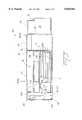
FIG. 5 is a sectional side view of the optical fiber splice housing and raceway unit of FIG. 4, taken along line 5--5 of FIG. 4.
DETAILED DESCRIPTION
Referring now to the drawings, wherein like reference characters designate like or corresponding parts throughout several views, an optical fiber splice housing forming one embodiment of the present invention is illustrated. Referring first to FIG. 1, a front view of a fiber optic distribution center 20 is shown which can incorporate an optical fiber splice housing according to the current invention. The typical distribution center 20 comprises one or more vertical equipment stacks 22, also known as bays, each comprising several components supported by vertical frame members 24. The frame members 24 may be attached to a wall or free standing on the floor. The distribution facility shown in FIG. 1 comprises two equipment bays 22, however, it will be readily apparent that the number of bays to be used will be dependent on the number of connections required in the distribution facility. When multiple adjacent bays are used as shown in FIG. 1, an inter-bay storage unit 25 may be positioned between bays 22 to further aid in cable management.
Referring still to FIG. 1, each equipment bay 22 typically includes at least one optical fiber connector housing 26, also known as a patch panel, and at least one horizontal raceway 28 positioned above and adjacent each connector housing 26. In the distribution facility shown in FIG. 1, each equipment bay 22 has two connector housing 26 and two horizontal raceways 28. As best seen in the connector panel marked 26a, which has the door removed for purposes of illustration, each connector housing 26 includes a connector panel 30 for interconnecting individual optical fibers 32 at the front side of connector panel 30 to other optical fibers (not shown) at the rear side of connector panel 30. The connector housing 26 can further include a plurality of cable management brackets 34 positioned below the connector panel to facilitate the routing of optical fibers 32. As best seen in the horizontal raceway 28a, which has a front cover removed for the purposes of illustration, each horizontal raceway 28 can also include a plurality of cable management brackets 35 to facilitate the routing of optical fibers 32 from connector panel 30 through the top of the connector housing 26 and along raceway 28. The optical fibers 32 from each connector housing 26 can then be routed via the horizontal raceways 28 and the inter-bay storage unit 25 to other connector housings 26 in the distribution facility 20 or to optical cables for interconnection with other parts of the user's facility. After installation or maintenance of the optical fibers, a door 36, best seen on housings marked 26b, can be shut over the forward cable area of each connector housing 26 to protect the fibers and connectors from damage. Similarly, protective covers 38 can be affixed on the horizontal raceways 28, best seen in horizontal raceways marked 28b, to further protect the optical fibers routed therethrough.
In the distribution frame 22 shown in FIG. 1, the connector housings 26 and raceway units 28 have a total vertical component height, Hc, and a total horizontal component width, Wc, as shown. When the splicing method of fiber connectorization is used, it is necessary to provide storage space for the splice tray units. It is known in the industry to provide a separate splice tray housing in the distribution frame to provide such storage space for the splice tray units, however, this will increase Hc or Wc for the distribution frame. It also is known to allocate space within a connector panel housing to provide storage space for the splice tray units, however, this takes up room normally reserved for the routing of fibers, and thus tends to reduce the fiber density available in that patch panel. Because of space limitations in many premises installations, it is desirable to minimize Hc and Wc to the extent possible, and also to provide connector panel housings with unobstructed fiber routing spaces to allow for high fiber connection densities. The current invention provides an apparatus allowing the storage of splice trays in the distribution frame without utilizing additional vertical or horizontal space in the distribution frame and without taking up room in the interior of connector panel housings.
Referring now to FIG. 2, a Prior Art optical fiber raceway unit 28 is shown. Raceway unit 28 includes a raceway member 40 which is adapted for mounting in a distribution frame (not shown). The raceway unit 28 shown in FIG. 2 has a plurality of mounting holes 42 formed in mounting flanges 44 for mounting the raceway unit to the distribution frame, however, other mounting means are known in the art. Raceway member 40 further includes a front side 46 defining a raceway height, HR, and a raceway width, WR. A plurality of cable management brackets 35 are mounted to the front side 46 of raceway member 40. Each bracket 35 can have a slot 47 to facilitate the positioning of optical fiber 32 (shown in phantom) within the cable routing area 48 defined by each bracket. The raceway member 40 further comprises a rear side 50 which faces away from the cable management brackets 35 and is generally accessible only from the rear side of the distribution frame. When the rear side 50 of the raceway unit 28 does not include brackets or other cable management devices, then a dead space 52 (shown in phantom) is said to exist behind rear side 50 of the raceway unit. As previously discussed, a cover 38 can be provided for raceway unit 28 to further protect fibers 32 being routed through cable management brackets 35. In the embodiment shown in FIG. 2, cover 38 is releasably mounted to cable management brackets 35 by connector pins 54 which interconnect with connector holes 56 formed in one or more of the cable management brackets 35. While preferred, the use of cover 38 is optional.
Referring now to FIG. 3, a rear perspective view is shown of an optical fiber splice housing 58, according to one aspect of the current invention, positioned behind a horizontal raceway unit 28 as previously described. Splice housing 58 comprises a cabinet 60 having a front end 62 defining a cabinet height, HS, and a cabinet width, WS and a rear end 64 defining a rear facing opening 66. The front end 62 of the cabinet 60 is adapted for connection to a distribution frame (not shown) adjacent to the rear side 50 of the raceway unit 28. In the embodiment shown, splice housing 58 includes mounting holes 68 formed in mounting flanges 70 connected to the front end 62 of cabinet 60. Housing 58 can thus be connected to a distribution frame adjacent to raceway 28 in one of two ways. First, the raceway unit 28 may be attached to the front side of the distribution frame members using fasteners (not shown) passing through mounting holes 42 in mounting flanges 44 while the splice housing 58 is attached to the rear side of the distribution frame members using additional fasteners (not shown) passing through mounting holes 68 in mounting flanges 70. Alternatively, both splice housing 58 and raceway unit 28 may be attached to the front side of the distribution frame members by aligning the mounting holes 68 and 42 of the respective units and using a single set of fasteners (not shown) to hold the units 58, 28 together and to the distribution frame member. The cabinet height, HS, of cabinet 60 is not greater than the raceway height, HR, of the raceway member 28 and the cabinet width, WS, of cabinet 60 is not greater than the raceway width, WR, of the raceway member 28, therefore, splice housing 58 fits within the dead zone 52 (best seen in FIG. 2), which is normally wasted space on the rear side of the distribution frame. Referring still to FIG. 3, the splice housing 58 further comprises a splice tray shelf 72 for removably mounting at least one optical fiber splice tray 74 in the cabinet 60. The splice housing 58 according to the current invention can be connected to a distribution frame adjacent to the rear side 50 of a raceway unit 28 without using additional vertical space in the frame. Access to the splice tray 74 mounted on the splice tray shelf 72 can be had through the rear facing opening 66 of the cabinet 60. The space-saving nature of this invention is of particular utility for distribution frames being used in the premises market because it does not require additional vertical rack space in the distribution frame, while at the same time, it does not require space within the connector panel housings to be allocated for the storage of splice trays.
Referring now also to FIGS. 4 and 5, an optical fiber splice housing and raceway unit 80, according to another aspect of the current invention, is shown. The splice housing and raceway unit 80 comprises a raceway member 82 and a splice housing member 84 and is adapted for mounting in a distribution frame. It will be readily apparent that the majority of elements comprising raceway member 82 are similar to the like-numbered elements of the stand-alone raceway unit 28 previously discussed, and the majority of elements of splice housing member 84 are identical to like-numbered elements in the stand-alone splice housing unit 58 previously described. Thus, the following description of additional embodiments of the current invention is generally applicable to both the stand-alone splice housing unit aspect and the combined splice housing and raceway unit aspect unless specifically stated otherwise.
Referring now to FIGS. 3 and 5, in a preferred embodiment of the current invention, the splice tray shelf 72 is adapted to mount a plurality of fiber optic splice trays. In this embodiment (best seen in FIG. 5), splice tray shelf 72 comprises a plurality of support elements 86 which are generally parallel and spaced apart from one another to form tray gaps 88 therebetween for holding splice trays 74. In this embodiment, five support elements 86 are provided forming four gaps 88, three of which are shown empty and one of which is shown holding a splice tray 74 in FIG. 5. In addition, because the inherent mechanical springiness of the fibers leading into the splice tray can sometimes inadvertently dislodge splice trays 74 from the splice tray shelf 72, a retaining device 90 can be provided to prevent the unintentional movement of the splice trays. In the embodiment shown, retaining device 90 comprises a strap 92 of hook-and-loop material (such as that sold under the trademark Velcro®) which may be affixed to a latch 94 of compatible hook-and-loop material whereby the strap 92 can be disengaged from the latch 94 when access to the splice trays 74 is required and then readily reengaged to secure the splice trays once maintenance activities are completed.
Referring still to FIGS. 3 and 5, a slack-storage apparatus 96 can be provided in cabinet 60 adjacent the splice tray shelf 72 to aid in the routing and storage of slack in the fibers being routed to the splice trays. In the embodiment shown in FIG. 3, slack storage apparatus 96 comprises a pair of storage spools 98 mounted on a storage platform 100 disposed above adjacent to splice tray shelf 72. It will be readily apparent, however, that other configurations for slack storage apparatus 96 as known in the art could be used without departing from the scope of the current invention.
Referring now also to FIG. 4, to provide for increased security and protection of the fibers and splice trays, cabinet 60 can further comprise a door 102 pivotally attached to the rear end 64 for enclosing the rear facing opening 66 and at least one opening 104 formed in the cabinet for passing optical fibers 32 therethrough. In the embodiment shown, door 102 is connected to cabinet 60 by hinges 103 and further comprises a latch mechanism 108 for securing the door in a closed position. While preferred, latch mechanism 108 is optional. It will be readily apparent that openings have a number of configurations can be formed in cabinet 60 for passing optical fibers 32 therethrough. As best seen in FIG. 3, these include openings 104 formed in the sides of cabinet 60, thereby allowing incoming fibers (marked as 32c) to be advantageously routed to slack storage apparatus 96. As best seen in FIG. 5, cabinet 60 can further include openings 106 formed in the bottom, thereby allowing outgoing fibers to be routed to below adjacent connector panel housings. As best seen in FIGS. 3 and 4, the cabinet 60 can further include knockout panels 110 formed on the top allowing the user the option to form additional openings if necessary for the convenient routing of fibers.
Referring again to FIGS. 3 and 5, in another embodiment of the current invention, and applicable to both of the splice housing aspect and the splice housing and raceway unit aspect, splice housing cabinet 60 can further comprise a drawer 112 having the splice tray shelf 72 mounted thereupon. The drawer 112 is slidably mounted within the cabinet 60 so that the drawer can be pulled out in a horizontal direction from the rear facing opening 66, thereby enhancing access to the splice tray shelf 72 and any splice trays 74 mounted thereupon. The drawer 112 may be slidably mounted to cabinet 60 on rail members 114 (best seen in FIG. 3) or by other mechanisms known in the art. A stop member (not shown) can be provided on cabinet 60 for arresting the rearward movement of the drawer 112 when the drawer is pulled out from the rear facing openings of cabinet 60. In a more preferred embodiment, a door 102 is pivotally attached to a rear edge 116 of the drawer 112, for enclosing the rear facing opening 66 when the drawer 112 is not pulled out of the cabinet 60, and at least one opening is formed in the cabinet for passing optical fibers 32 therethrough.
In the embodiment shown in FIG. 3, in addition to side openings 104 and bottom openings 106 (best seen in FIG. 5), when drawer 112 is used, additional openings 107 can be formed in drawer 112 for passing optical fibers 32 therethrough whether or not the drawer has been pulled from the cabinet. In FIG. 3, outgoing fibers, marked 32d, are shown passing through opening 107 in drawer 112 for convenient routing to equipment positioned beneath splice housing 58.
Although several embodiments of the present invention have been illustrated in the accompanying drawings and described in the foregoing Detailed Description, it will be understood that the invention is not limited to the embodiments disclosed, but is capable of numerous rearrangements, modifications and substitution of parts and elements without departing from the scope and spirit of the invention.

Claims (17)

We claim:
1. An optical fiber splice housing for mounting adjacent to an optical fiber raceway unit of a type including a raceway member being adapted for mounting in a distribution frame and having a front side defining a raceway height and a raceway width, a plurality of cable management brackets mounted to the front side, and a rear side opposite the front side, said splice housing comprising:
(a) a cabinet having a front end defining a cabinet height and a cabinet width, and a rear end defining a rear-facing opening;
said front end of said cabinet being adapted for connection to a distribution frame adjacent the rear side of said raceway unit;
said cabinet height being not greater that the raceway height of said raceway member; said cabinet width being not greater than said raceway width of said raceway member; and
(b) a splice tray shelf for removably mounting at least one optical fiber splice tray within said cabinet;
whereby said splice housing can be connected to said distribution frame adjacent the rear side of said raceway unit without using additional vertical space in said frame and whereby a splice tray mounted on said splice tray shelf is accessible through the rear-facing opening of said cabinet.
2. An optical fiber splice housing according to claim 1, wherein said splice tray shelf is adapted to mount a plurality of fiber optic splice trays.
3. An optical fiber splice housing according to claim 2, further comprising a slack-storage spool mounted in said cabinet adjacent said splice tray shelf.
4. An optical fiber splice housing according to claim 2, further comprising:
(a) a door pivotally attached to said rear end of said cabinet for enclosing said rear-facing opening of said cabinet; and
(b) at least one opening formed in said cabinet for passing optical fibers therethrough.
5. An optical fiber splice housing according to claim 1, further comprising a drawer having said splice tray shelf mounted thereupon;
said drawer being slidably mounted within said cabinet so that said drawer can be pulled out in a horizontal direction from the rear-facing opening of said cabinet;
whereby access to said splice tray shelf is enhanced when said drawer is pulled out of said cabinet.
6. An optical fiber splice housing according to claim 5, wherein said splice tray shelf mounted on said drawer is adapted to mount a plurality of fiber optic splice trays.
7. An optical fiber splice housing according to claim 6, further comprising a slack-storage spool mounted on said drawer adjacent said splice tray shelf.
8. An optical fiber splice housing according to claim 5, further comprising a stop member for arresting the rearward movement of said drawer when the drawer is pulled out from rear-facing opening of the cabinet.
9. An optical fiber splice housing according to claim 5, further comprising:
(a) a door pivotally attached to a rear edge of said drawer for enclosing said rear-facing opening of said cabinet when said drawer is not pulled out of said cabinet; and
(b) at least one opening formed in said cabinet for passing optical fibers therethrough.
10. An optical fiber splice housing and raceway unit comprising:
(a) a raceway member being adapted for mounting to a distribution frame and having a front side defining a raceway height and a raceway width, cable management brackets mounted to the front side and a rear side opposite the front side;
(b) a splice housing member including:
(i) a cabinet having a front end defining a cabinet height and a cabinet width and a rear end defining a rear-facing opening;
said front end of said cabinet being connected to the rear side of said raceway unit;
said cabinet height being not greater than said raceway height;
said cabinet width being not greater than said raceway width;
(ii) a splice tray shelf for removably mounting at least one optical fiber splice tray within said cabinet;
whereby said splice housing and raceway unit can be mounted to a distribution frame and whereby a splice tray mounted on said splice tray shelf is accessible through the rear-facing opening of said cabinet.
11. An optical fiber splice housing and raceway unit according to claim 10, wherein said splice tray shelf is adapted to mount a plurality of fiber optic splice trays.
12. An optical fiber splice housing and raceway unit according to claim 11, further comprising a slack-storage spool mounted in said cabinet adjacent said splice tray shelf.
13. An optical fiber splice housing and raceway unit according to claim 12, further comprising:
(a) a door pivotally attached to said rear end of said cabinet for enclosing said rear-facing opening of said cabinet; and
(b) at least one opening formed in said cabinet for passing optical fibers therethrough.
14. An optical fiber splice housing and raceway unit according to claim 10, further comprising a drawer having said splice tray shelf mounted thereupon;
said drawer slidably mounted within said cabinet so that said drawer can be pulled out in a horizontal direction from the rear-facing opening of said cabinet, thereby enhancing access to said splice tray shelf.
15. An optical fiber splice housing and raceway unit according to claim 14, further comprising a stop member for arresting the rearward movement of said drawer when the drawer is pulled out from rear-facing opening of the cabinet.
16. An optical fiber splice housing and raceway unit according to claim 14, further comprising:
(a) a door pivotally attached to a rear edge of said drawer for enclosing said rear-facing opening of said cabinet when said drawer is not pulled out of said cabinet; and
(b) at least one opening formed in said cabinet for passing optical fibers therethrough.
17. A fiber distribution frame comprising:
(a) at least one connector housing for the interconnection of optical fiber cables, the connector housing generally box shaped and having a top and a bottom and a front side facing frontward and a rear side facing rearward, the at least one connector housing having a depth defined between the front and the rear side;
(b) a horizontal raceway mounted along the top or bottom of at least one of the at least one connector housing, the raceway having a top and a bottom and a front side facing frontward for managing cables that are routed therealong and a rear side opposite thereto, the at least one raceway having a depth defined between the front side and the rear side, the depth of the raceway being less than the depth of the at least one connector housing and the rear side of the raceway being located frontward of the rear side of the connector housing, the raceway having a height defined between the top and the bottom; and
(c) a splice housing for containing splices or other connections to any cables egressing from the rear side of the connector housing mounted rearward of the horizontal raceway and generally co-planar therewith, the splice housing having a height substantially equal to that of the raceway and having a depth such that it generally extends the distance from the rear side of the raceway to the rear side of the connector housing.
US08/775,678 1996-12-31 1996-12-31 Optical fiber splice housing Expired - Fee Related US5825962A (en)

Priority Applications (4)

Application Number Priority Date Filing Date Title
US08/775,678 US5825962A (en) 1996-12-31 1996-12-31 Optical fiber splice housing
CA002221839A CA2221839A1 (en) 1996-12-31 1997-11-21 Optical fiber splice housing
DE69720165T DE69720165T2 (en) 1996-12-31 1997-12-19 Fiber optic distribution system
EP97122549A EP0851255B1 (en) 1996-12-31 1997-12-19 Optical fiber distribution facility

Applications Claiming Priority (1)

Application Number Priority Date Filing Date Title
US08/775,678 US5825962A (en) 1996-12-31 1996-12-31 Optical fiber splice housing

Publications (1)

Publication Number Publication Date
US5825962A true US5825962A (en) 1998-10-20

Family

ID=25105157

Family Applications (1)

Application Number Title Priority Date Filing Date
US08/775,678 Expired - Fee Related US5825962A (en) 1996-12-31 1996-12-31 Optical fiber splice housing

Country Status (4)

Country Link
US (1) US5825962A (en)
EP (1) EP0851255B1 (en)
CA (1) CA2221839A1 (en)
DE (1) DE69720165T2 (en)

Cited By (50)

* Cited by examiner, † Cited by third party
Publication number Priority date Publication date Assignee Title
US6044193A (en) * 1998-07-10 2000-03-28 Siecor Operations, Llc Fiber optic interconnection enclosure having a forced air system
US6120193A (en) * 1997-12-22 2000-09-19 Siecor Corporation Splice house subassembly and associated connector
EP1039326A1 (en) * 1999-03-19 2000-09-27 Siecor Operations, LLC Panel for managing jumper storage
US6157766A (en) * 1997-06-20 2000-12-05 Frances Telecom High-density and high-capacity distribution frame for optical fibers
US6215064B1 (en) * 1999-03-19 2001-04-10 Siecor Operations, Llc Electronics jumper management assembly
US6301424B1 (en) * 2000-04-13 2001-10-09 Lucent Technologies Inc. Distribution frame cable routing apparatus
US6330389B1 (en) * 1999-11-18 2001-12-11 Lucent Technologies, Inc. System for organizing optical fibers
US6396992B1 (en) 1999-01-14 2002-05-28 Thomas & Betts International, Inc. Integral patch panel and cable management tray assembly and method of manufacture
US6504094B2 (en) * 2000-07-12 2003-01-07 Alcatel Canada Inc. Mounting apparatus for equipment enclosures having cable bend radius control and channel for retaining cable
US6515227B1 (en) 2002-05-24 2003-02-04 Alcoa Fujikura Limited Fiber optic cable management enclosure with integral bend radius control
WO2003034562A2 (en) * 2001-10-18 2003-04-24 I-Bus/Phoenix, Inc. Cable management device for rack mounted equipment
KR20030052674A (en) * 2001-12-21 2003-06-27 우리로광통신주식회사 Chassis for optical splitter module
US20030228121A1 (en) * 2002-06-11 2003-12-11 Thomas Dwyer Interbay housing assembly for fiber optic management systems
US6678456B2 (en) * 2000-04-14 2004-01-13 Ciena Corporation Fiber optic cable management system
US6728461B1 (en) 2003-03-13 2004-04-27 Marc Senatore Optical fiber cable manager
US6734354B2 (en) * 2002-04-05 2004-05-11 Adc Telecommunications, Inc. Cable management apparatus
US20040228598A1 (en) * 2003-03-20 2004-11-18 Allen Barry W. Optical fiber interconnect cabinets, termination modules and fiber connectivity management for the same
US20050111809A1 (en) * 2003-11-26 2005-05-26 Giraud William J. Connector housing having a sliding tray with a hingeable portion
US20050111810A1 (en) * 2003-11-26 2005-05-26 Giraud William J. Connector housing for a communication network
US20050237721A1 (en) * 2004-04-27 2005-10-27 Cowley Simon C Articulated high density fiber optic splice and termination shelf
US20060018622A1 (en) * 2004-07-22 2006-01-26 Caveney Jack E Front access punch down patch panel
US20060021789A1 (en) * 2004-07-15 2006-02-02 Sachiko Nishikino External device and electronic apparatus
US20060032990A1 (en) * 2004-08-11 2006-02-16 Cask John A Rack and duct system
US20060215980A1 (en) * 2005-03-24 2006-09-28 Yilmaz Bayazit Splice tray arrangement
US20070047892A1 (en) * 2005-08-25 2007-03-01 Yilmaz Bayazit Splice chip device
US20070047891A1 (en) * 2005-08-25 2007-03-01 Yilmaz Bayazit Stackable splice chip device
US20070104425A1 (en) * 2005-10-24 2007-05-10 3M Innovative Properties Company Optical connector and fiber distribution unit
US20070139868A1 (en) * 2005-11-30 2007-06-21 Labinal Electrical cabinet including a wiring support
US20070172192A1 (en) * 2005-12-02 2007-07-26 Adc Telecommunications, Inc. Splice tray arrangement
US20070175125A1 (en) * 2006-01-10 2007-08-02 Specified Technologies Inc. Apparatus for adjustably retaining and sealing pathway conduits mounted extending through a wall panel
US7255234B2 (en) * 2000-04-24 2007-08-14 Hewlett-Packard Development Company, L.P. Low profile support system for device rack-mounting
US20070210679A1 (en) * 2006-03-13 2007-09-13 Panduit Corp. Network Cabinet
US20080050083A1 (en) * 2006-08-25 2008-02-28 Frazier Brent M Fiber optic housing assembly for fiber optic connections comprising pivotable portion
US7406242B1 (en) 2007-11-16 2008-07-29 Tyco Electronics Co., Ltd. Interconnect enclosures for optical fibers including cross-connect modules and methods for using the same
US20090022457A1 (en) * 2007-07-16 2009-01-22 De Jong Michael Fusion-splice fiber optic connectors and related tools
US20100006317A1 (en) * 2007-07-09 2010-01-14 Adc Telecommunications, Inc. Telecommunications frame including an internal cable trough assembly
US20100080512A1 (en) * 2008-09-05 2010-04-01 Chris Taylor Patch panel assembly
WO2010077856A1 (en) * 2008-12-17 2010-07-08 3M Innovative Properties Company Modular fiber distribution unit
US20100224578A1 (en) * 2009-03-09 2010-09-09 Patrick Fariello Methods of Converting Patching System To Intelligent Patching System and Related Shelf Units
US20110110640A1 (en) * 2009-11-11 2011-05-12 Fumitoshi Goto Optical communication module, optical fiber support fixture, and optical fiber wiring method
US20120314357A1 (en) * 2011-06-10 2012-12-13 Hon Hai Precision Industry Co., Ltd. Server enclosure
US8457464B2 (en) 2011-09-26 2013-06-04 Hubbell Incorporated Cable enclosure and radius-limiting cable guide with integral magnetic door catch
US20140133819A1 (en) * 2000-01-24 2014-05-15 Adc Telecommunications, Inc. Cable Management Panel with Sliding Drawer
US20160349472A1 (en) * 2015-05-27 2016-12-01 3M Innovative Properties Company Fiber management assemblies and network interface devices incorporating such assemblies
US20180120528A1 (en) * 1999-03-01 2018-05-03 Commscope Technologies Llc Optical fiber distribution frame with outside plant enclosure
US20180129005A1 (en) * 2016-11-08 2018-05-10 Ortronics, Inc. Splice Managers and Related Methods of Use
US20190196127A1 (en) * 2017-12-27 2019-06-27 Afl Ig Llc Optical distribution frames
US20190250355A1 (en) * 2018-02-15 2019-08-15 Panduit Corp. Rack-mountable fiber optic splice enclosure
US10416406B1 (en) 2018-03-01 2019-09-17 Afl Telecommunications Llc Communications module housing
US10451828B1 (en) 2018-11-09 2019-10-22 Afl Telecommunications Llc Communications module housing

Families Citing this family (2)

* Cited by examiner, † Cited by third party
Publication number Priority date Publication date Assignee Title
WO2015034811A1 (en) * 2013-09-06 2015-03-12 Corning Optical Communications LLC Optical fiber cassette systems with fiber retaining covers
WO2020133220A1 (en) * 2018-12-28 2020-07-02 华为技术有限公司 Optical distribution frame and main distribution frame

Citations (12)

* Cited by examiner, † Cited by third party
Publication number Priority date Publication date Assignee Title
US4630886A (en) * 1984-04-16 1986-12-23 At&T Bell Laboratories Lightguide distributing unit
US4708430A (en) * 1984-10-25 1987-11-24 Northern Telecom Limited Cabinet for optical cable terminating equipment
US4911662A (en) * 1988-12-20 1990-03-27 Northern Telecom Limited Distribution frame for telecommunications cable
US5093885A (en) * 1990-07-11 1992-03-03 Adc Telecommunications, Inc. Fiber optic connector module
US5100221A (en) * 1990-01-22 1992-03-31 Porta Systems Corp. Optical fiber cable distribution frame and support
US5129030A (en) * 1991-05-30 1992-07-07 At&T Bell Laboratories Movable lightguide connector panel
US5179618A (en) * 1990-07-11 1993-01-12 Adc Telecommunications, Inc. Fiber optic connector module
US5303320A (en) * 1992-09-21 1994-04-12 David B. Duffie Fiber optic signal distribution system and raceway and panel associated therewith
US5339379A (en) * 1993-06-18 1994-08-16 Telect, Inc. Telecommunication fiber optic cable distribution apparatus
US5363465A (en) * 1993-02-19 1994-11-08 Adc Telecommunications, Inc. Fiber optic connector module
US5402515A (en) * 1994-03-01 1995-03-28 Minnesota Mining And Manufacturing Company Fiber distribution frame system, cabinets, trays and fiber optic connector couplings
USRE34955E (en) * 1989-07-31 1995-05-30 Adc Telecommunications, Inc. Optical fiber distribution frame

Family Cites Families (5)

* Cited by examiner, † Cited by third party
Publication number Priority date Publication date Assignee Title
US4900123A (en) * 1988-08-29 1990-02-13 Gte Products Corporation 1550 nm fiber distribution panel
US5142607A (en) * 1990-03-20 1992-08-25 Rittal-Werk Rudolf Loh Gmbh & Co. Kg Splice box for optical wave guide
US5231687A (en) * 1990-06-04 1993-07-27 Bicc Plc Termination system for optical fibres
US5490229A (en) * 1993-12-08 1996-02-06 At&T Ipm Corp. Slidably mounted optical fiber distribution tray
US5559922A (en) * 1995-02-28 1996-09-24 Lucent Technologies Inc. Wire guide and optical fiber storage spool assembly

Patent Citations (12)

* Cited by examiner, † Cited by third party
Publication number Priority date Publication date Assignee Title
US4630886A (en) * 1984-04-16 1986-12-23 At&T Bell Laboratories Lightguide distributing unit
US4708430A (en) * 1984-10-25 1987-11-24 Northern Telecom Limited Cabinet for optical cable terminating equipment
US4911662A (en) * 1988-12-20 1990-03-27 Northern Telecom Limited Distribution frame for telecommunications cable
USRE34955E (en) * 1989-07-31 1995-05-30 Adc Telecommunications, Inc. Optical fiber distribution frame
US5100221A (en) * 1990-01-22 1992-03-31 Porta Systems Corp. Optical fiber cable distribution frame and support
US5093885A (en) * 1990-07-11 1992-03-03 Adc Telecommunications, Inc. Fiber optic connector module
US5179618A (en) * 1990-07-11 1993-01-12 Adc Telecommunications, Inc. Fiber optic connector module
US5129030A (en) * 1991-05-30 1992-07-07 At&T Bell Laboratories Movable lightguide connector panel
US5303320A (en) * 1992-09-21 1994-04-12 David B. Duffie Fiber optic signal distribution system and raceway and panel associated therewith
US5363465A (en) * 1993-02-19 1994-11-08 Adc Telecommunications, Inc. Fiber optic connector module
US5339379A (en) * 1993-06-18 1994-08-16 Telect, Inc. Telecommunication fiber optic cable distribution apparatus
US5402515A (en) * 1994-03-01 1995-03-28 Minnesota Mining And Manufacturing Company Fiber distribution frame system, cabinets, trays and fiber optic connector couplings

Cited By (111)

* Cited by examiner, † Cited by third party
Publication number Priority date Publication date Assignee Title
US6157766A (en) * 1997-06-20 2000-12-05 Frances Telecom High-density and high-capacity distribution frame for optical fibers
US6120193A (en) * 1997-12-22 2000-09-19 Siecor Corporation Splice house subassembly and associated connector
US6044193A (en) * 1998-07-10 2000-03-28 Siecor Operations, Llc Fiber optic interconnection enclosure having a forced air system
US6396992B1 (en) 1999-01-14 2002-05-28 Thomas & Betts International, Inc. Integral patch panel and cable management tray assembly and method of manufacture
US10067309B2 (en) * 1999-03-01 2018-09-04 Commscope Technologies Llc Optical fiber distribution frame with outside plant enclosure
US20180120528A1 (en) * 1999-03-01 2018-05-03 Commscope Technologies Llc Optical fiber distribution frame with outside plant enclosure
US6215064B1 (en) * 1999-03-19 2001-04-10 Siecor Operations, Llc Electronics jumper management assembly
US6353696B1 (en) 1999-03-19 2002-03-05 Corning Cable Systems Llc Panel for managing jumper storage
EP1039326A1 (en) * 1999-03-19 2000-09-27 Siecor Operations, LLC Panel for managing jumper storage
US6330389B1 (en) * 1999-11-18 2001-12-11 Lucent Technologies, Inc. System for organizing optical fibers
US20140133819A1 (en) * 2000-01-24 2014-05-15 Adc Telecommunications, Inc. Cable Management Panel with Sliding Drawer
US9664870B2 (en) * 2000-01-24 2017-05-30 Commscope Technologies Llc Cable management panel with sliding drawer
US20170351046A1 (en) * 2000-01-24 2017-12-07 Commscope Technologies Llc Cable management panel with sliding drawer
US10459182B2 (en) * 2000-01-24 2019-10-29 Commscope Technologies Llc Cable management panel with sliding drawer
US6301424B1 (en) * 2000-04-13 2001-10-09 Lucent Technologies Inc. Distribution frame cable routing apparatus
US6678456B2 (en) * 2000-04-14 2004-01-13 Ciena Corporation Fiber optic cable management system
US7255234B2 (en) * 2000-04-24 2007-08-14 Hewlett-Packard Development Company, L.P. Low profile support system for device rack-mounting
US6504094B2 (en) * 2000-07-12 2003-01-07 Alcatel Canada Inc. Mounting apparatus for equipment enclosures having cable bend radius control and channel for retaining cable
WO2003034562A3 (en) * 2001-10-18 2003-12-24 I Bus Phoenix Inc Cable management device for rack mounted equipment
US20030079901A1 (en) * 2001-10-18 2003-05-01 I-Bus Corporation Cable management device for rack mounted equipment
WO2003034562A2 (en) * 2001-10-18 2003-04-24 I-Bus/Phoenix, Inc. Cable management device for rack mounted equipment
KR20030052674A (en) * 2001-12-21 2003-06-27 우리로광통신주식회사 Chassis for optical splitter module
US6734354B2 (en) * 2002-04-05 2004-05-11 Adc Telecommunications, Inc. Cable management apparatus
US6515227B1 (en) 2002-05-24 2003-02-04 Alcoa Fujikura Limited Fiber optic cable management enclosure with integral bend radius control
US6845206B2 (en) 2002-06-11 2005-01-18 Alcoa Fujikura Limited Interbay housing assembly for fiber optic management systems
US20030228121A1 (en) * 2002-06-11 2003-12-11 Thomas Dwyer Interbay housing assembly for fiber optic management systems
US6728461B1 (en) 2003-03-13 2004-04-27 Marc Senatore Optical fiber cable manager
USRE48675E1 (en) 2003-03-20 2021-08-10 Commscope Technologies Llc Optical fiber interconnect cabinets, termination modules and fiber connectivity management for the same
US20040228598A1 (en) * 2003-03-20 2004-11-18 Allen Barry W. Optical fiber interconnect cabinets, termination modules and fiber connectivity management for the same
US7142764B2 (en) * 2003-03-20 2006-11-28 Tyco Electronics Corporation Optical fiber interconnect cabinets, termination modules and fiber connectivity management for the same
US20070036507A1 (en) * 2003-03-20 2007-02-15 Allen Barry W Optical fiber interconnect cabinets, termination modules and fiber connectivity management for the same
US7298952B2 (en) 2003-03-20 2007-11-20 Tyco Electronics Corporation Optical fiber interconnect cabinets, termination modules and fiber connectivity management for the same
USRE44758E1 (en) 2003-03-20 2014-02-11 Adc Telecommunications, Inc. Optical fiber interconnect cabinets, termination modules and fiber connectivity management for the same
USRE46945E1 (en) 2003-03-20 2018-07-10 Commscope Technologies Llc Optical fiber interconnect cabinets, termination modules and fiber connectivity management for the same
US20050111810A1 (en) * 2003-11-26 2005-05-26 Giraud William J. Connector housing for a communication network
US20050111809A1 (en) * 2003-11-26 2005-05-26 Giraud William J. Connector housing having a sliding tray with a hingeable portion
US7200316B2 (en) 2003-11-26 2007-04-03 Corning Cable Systems Llc Connector housing for a communication network
US6944389B2 (en) * 2003-11-26 2005-09-13 Corning Cable Systems Llc Connector housing having a sliding tray with a hingeable portion
US7031588B2 (en) * 2004-04-27 2006-04-18 Commscope Solutions Properties, Llc Articulated high density fiber optic splice and termination shelf
US20050237721A1 (en) * 2004-04-27 2005-10-27 Cowley Simon C Articulated high density fiber optic splice and termination shelf
US20060021789A1 (en) * 2004-07-15 2006-02-02 Sachiko Nishikino External device and electronic apparatus
US7700876B2 (en) * 2004-07-15 2010-04-20 Ricoh Company, Ltd. External device and electronic apparatus
US7526171B2 (en) * 2004-07-22 2009-04-28 Panduit Corp. Front access punch down patch panel
US20060018622A1 (en) * 2004-07-22 2006-01-26 Caveney Jack E Front access punch down patch panel
US20060032990A1 (en) * 2004-08-11 2006-02-16 Cask John A Rack and duct system
US20060215980A1 (en) * 2005-03-24 2006-09-28 Yilmaz Bayazit Splice tray arrangement
US7463810B2 (en) 2005-08-25 2008-12-09 Adc Telecommunications, Inc. Splice chip device
US20070047891A1 (en) * 2005-08-25 2007-03-01 Yilmaz Bayazit Stackable splice chip device
US20090136185A1 (en) * 2005-08-25 2009-05-28 Adc Telecommunications, Inc. Splice chip device
US7684669B2 (en) 2005-08-25 2010-03-23 Adc Telecommunications, Inc. Splice chip device
US7764858B2 (en) 2005-08-25 2010-07-27 Adc Telecommunications, Inc. Stackable splice chip device
US20080181569A1 (en) * 2005-08-25 2008-07-31 Adc Telecommunications, Inc. Stackable splice chip device
US7272291B2 (en) 2005-08-25 2007-09-18 Adc Telecommunications, Inc. Splice chip device
US7421182B2 (en) 2005-08-25 2008-09-02 Adc Telecommunications, Inc. Stackable splice chip device
US20070047892A1 (en) * 2005-08-25 2007-03-01 Yilmaz Bayazit Splice chip device
US7310471B2 (en) 2005-08-25 2007-12-18 Adc Telecommunications, Inc. Stackable splice chip device
US20070104425A1 (en) * 2005-10-24 2007-05-10 3M Innovative Properties Company Optical connector and fiber distribution unit
US7369738B2 (en) 2005-10-24 2008-05-06 3M Innovative Properties Company Optical connector and fiber distribution unit
US7547845B2 (en) * 2005-11-30 2009-06-16 Labinal Electrical cabinet including a wiring support
US20070139868A1 (en) * 2005-11-30 2007-06-21 Labinal Electrical cabinet including a wiring support
US7457504B2 (en) 2005-12-02 2008-11-25 Adc Telecommunications, Inc. Splice tray arrangement
US20070172192A1 (en) * 2005-12-02 2007-07-26 Adc Telecommunications, Inc. Splice tray arrangement
US7274852B1 (en) 2005-12-02 2007-09-25 Adc Telecommunications, Inc. Splice tray arrangement
US20090136195A1 (en) * 2005-12-02 2009-05-28 Adc Telecommunications, Inc. Splice tray arrangement
US7620288B2 (en) 2005-12-02 2009-11-17 Adc Telecommunications, Inc. Splice tray arrangement
US7427050B2 (en) * 2006-01-10 2008-09-23 Specified Technologies Inc. Apparatus for adjustably retaining and sealing pathway conduits mounted extending through a wall panel
US20070175125A1 (en) * 2006-01-10 2007-08-02 Specified Technologies Inc. Apparatus for adjustably retaining and sealing pathway conduits mounted extending through a wall panel
US8237052B2 (en) 2006-03-13 2012-08-07 Panduit Corp. Network cabinet
US7880084B2 (en) 2006-03-13 2011-02-01 Panduit Corp. Network cabinet
US7476804B2 (en) 2006-03-13 2009-01-13 Panduit Corp. Network cabinet
US7498512B2 (en) 2006-03-13 2009-03-03 Panduit Corp. Network cabinet
US7485803B2 (en) 2006-03-13 2009-02-03 Panduit Corp. Network cabinet
US7772489B2 (en) 2006-03-13 2010-08-10 Panduit Corp. Network cabinet
US20070210679A1 (en) * 2006-03-13 2007-09-13 Panduit Corp. Network Cabinet
US20100264788A1 (en) * 2006-03-13 2010-10-21 Panduit Corp. Network cabinet
US20080067904A1 (en) * 2006-03-13 2008-03-20 Panduit Corp. Network Cabinet
US20080036339A1 (en) * 2006-03-13 2008-02-14 Panduit Corp. Network Cabinet
US20110084580A1 (en) * 2006-03-13 2011-04-14 Panduit Corp. Network Cabinet
US7495169B2 (en) 2006-03-13 2009-02-24 Panduit Corp. Network cabinet
US8802978B2 (en) 2006-03-13 2014-08-12 Panduit Corp. Network cabinet
US20080050083A1 (en) * 2006-08-25 2008-02-28 Frazier Brent M Fiber optic housing assembly for fiber optic connections comprising pivotable portion
US7349615B2 (en) 2006-08-25 2008-03-25 Corning Cable Systems Llc Fiber optic housing assembly for fiber optic connections comprising pivotable portion
US7829787B2 (en) * 2007-07-09 2010-11-09 Adc Telecommunications, Inc. Telecommunications frame including an internal cable trough assembly
US20100006317A1 (en) * 2007-07-09 2010-01-14 Adc Telecommunications, Inc. Telecommunications frame including an internal cable trough assembly
US20090022457A1 (en) * 2007-07-16 2009-01-22 De Jong Michael Fusion-splice fiber optic connectors and related tools
US8408811B2 (en) 2007-07-16 2013-04-02 Corning Cable Systems Llc Fusion-splice fiber optic connectors and related tools
US7406242B1 (en) 2007-11-16 2008-07-29 Tyco Electronics Co., Ltd. Interconnect enclosures for optical fibers including cross-connect modules and methods for using the same
US8290330B2 (en) * 2008-09-05 2012-10-16 Adc Gmbh Patch panel assembly
US20100080512A1 (en) * 2008-09-05 2010-04-01 Chris Taylor Patch panel assembly
WO2010077856A1 (en) * 2008-12-17 2010-07-08 3M Innovative Properties Company Modular fiber distribution unit
US20100224578A1 (en) * 2009-03-09 2010-09-09 Patrick Fariello Methods of Converting Patching System To Intelligent Patching System and Related Shelf Units
US8753142B2 (en) 2009-03-09 2014-06-17 Commscope, Inc. Of North Carolina Methods of converting patching system to intelligent patching system and related shelf units
US20110110640A1 (en) * 2009-11-11 2011-05-12 Fumitoshi Goto Optical communication module, optical fiber support fixture, and optical fiber wiring method
US8822819B2 (en) * 2011-06-10 2014-09-02 Hong Fu Jin Precision Industry (Wuhan) Co., Ltd. Server enclosure
US20120314357A1 (en) * 2011-06-10 2012-12-13 Hon Hai Precision Industry Co., Ltd. Server enclosure
US8457464B2 (en) 2011-09-26 2013-06-04 Hubbell Incorporated Cable enclosure and radius-limiting cable guide with integral magnetic door catch
US20160349472A1 (en) * 2015-05-27 2016-12-01 3M Innovative Properties Company Fiber management assemblies and network interface devices incorporating such assemblies
US10001617B2 (en) * 2015-05-27 2018-06-19 3M Innovative Properties Company Fiber management assemblies and network interface devices incorporating such assemblies
US20180292622A1 (en) * 2015-05-27 2018-10-11 Corning Research & Development Corporation Fiber management assemblies and network interface devices incorporating such assemblies
US10788640B2 (en) * 2016-11-08 2020-09-29 Ortronics, Inc. Splice managers and related methods of use
US20180129005A1 (en) * 2016-11-08 2018-05-10 Ortronics, Inc. Splice Managers and Related Methods of Use
US10591692B2 (en) * 2017-12-27 2020-03-17 Afl Ig Llc Optical distribution frames
US20190196127A1 (en) * 2017-12-27 2019-06-27 Afl Ig Llc Optical distribution frames
US20190250355A1 (en) * 2018-02-15 2019-08-15 Panduit Corp. Rack-mountable fiber optic splice enclosure
US10641980B2 (en) * 2018-02-15 2020-05-05 Panduit Corp. Rack-mountable fiber optic splice enclosure
JP2021528675A (en) * 2018-02-15 2021-10-21 パンドウィット・コーポレーション Rack mount fiber optic splice enclosure
JP7053861B2 (en) 2018-02-15 2022-04-12 パンドウィット・コーポレーション Rack mount fiber optic splice enclosure
US10416406B1 (en) 2018-03-01 2019-09-17 Afl Telecommunications Llc Communications module housing
US10823927B2 (en) 2018-03-01 2020-11-03 Afl Telecommunications Llc Communications module housing
US10451828B1 (en) 2018-11-09 2019-10-22 Afl Telecommunications Llc Communications module housing
US10802235B2 (en) 2018-11-09 2020-10-13 Afl Telecommunications Llc Communications module housing

Also Published As

Publication number Publication date
DE69720165T2 (en) 2003-09-25
EP0851255A1 (en) 1998-07-01
DE69720165D1 (en) 2003-04-30
CA2221839A1 (en) 1998-06-30
EP0851255B1 (en) 2003-03-26

Similar Documents

Publication Publication Date Title
US5825962A (en) Optical fiber splice housing
US10429602B2 (en) Low profile fiber distribution hub
CA2221938C (en) Optical fiber connector housing
US6944387B2 (en) Fiber optic connector tray system
US6918786B2 (en) Angled patch panel with cable support bar for network cable racks
US6631237B2 (en) Termination and splice panel
US7333707B2 (en) Optical fiber distribution frame with outside plant enclosure
US8520996B2 (en) Removably mountable fiber optic terminal
US5758002A (en) Routing and storage apparatus for optical fibers
US6674952B2 (en) Fiber optic cable bend radius protection system
MXPA06013049A (en) Multi-position fiber optic connector holder for storing fiber optic connectors in telecommunications connection cabinet and corresponding method.
US10495834B2 (en) Optical fiber management
US6362422B1 (en) Enclosure for use in fiber optic management systems
JPH11202146A (en) Optical fiber splice housing
JP3881101B2 (en) Optical fiber connector housing

Legal Events

Date Code Title Description
AS Assignment

Owner name: SIECOR CORPORATION, NORTH CAROLINA

Free format text: ASSIGNMENT OF ASSIGNORS INTEREST;ASSIGNORS:WALTERS, MARK D.;MORGAN, KEVIN L.;DENNIS, ROBERT W.;REEL/FRAME:008508/0078

Effective date: 19970331

AS Assignment

Owner name: SIECOR TECHNOLOGY, INC., DELAWARE

Free format text: ASSIGNMENT OF ASSIGNORS INTEREST;ASSIGNOR:SIECOR CORPORATION;REEL/FRAME:009711/0103

Effective date: 19990120

FPAY Fee payment

Year of fee payment: 4

REMI Maintenance fee reminder mailed
LAPS Lapse for failure to pay maintenance fees
STCH Information on status: patent discontinuation

Free format text: PATENT EXPIRED DUE TO NONPAYMENT OF MAINTENANCE FEES UNDER 37 CFR 1.362

FP Lapsed due to failure to pay maintenance fee

Effective date: 20061020