US5826578A - Motion measurement apparatus - Google Patents
Motion measurement apparatus Download PDFInfo
- Publication number
- US5826578A US5826578A US08/250,152 US25015294A US5826578A US 5826578 A US5826578 A US 5826578A US 25015294 A US25015294 A US 25015294A US 5826578 A US5826578 A US 5826578A
- Authority
- US
- United States
- Prior art keywords
- movement
- user
- motion
- sample
- golfer
- Prior art date
- Legal status (The legal status is an assumption and is not a legal conclusion. Google has not performed a legal analysis and makes no representation as to the accuracy of the status listed.)
- Expired - Lifetime
Links
- 230000033001 locomotion Effects 0.000 title claims abstract description 342
- 238000005259 measurement Methods 0.000 title claims description 58
- 230000003287 optical effect Effects 0.000 claims description 5
- 230000008878 coupling Effects 0.000 claims 1
- 238000010168 coupling process Methods 0.000 claims 1
- 238000005859 coupling reaction Methods 0.000 claims 1
- 230000001105 regulatory effect Effects 0.000 claims 1
- 230000003111 delayed effect Effects 0.000 abstract description 2
- 210000000629 knee joint Anatomy 0.000 description 16
- 230000007246 mechanism Effects 0.000 description 11
- 230000000007 visual effect Effects 0.000 description 11
- 210000000707 wrist Anatomy 0.000 description 10
- 210000004247 hand Anatomy 0.000 description 9
- 210000003127 knee Anatomy 0.000 description 8
- 210000002414 leg Anatomy 0.000 description 8
- 230000006870 function Effects 0.000 description 7
- 238000001514 detection method Methods 0.000 description 4
- 238000000034 method Methods 0.000 description 4
- 238000012544 monitoring process Methods 0.000 description 4
- 210000002683 foot Anatomy 0.000 description 3
- 238000012986 modification Methods 0.000 description 3
- 230000004048 modification Effects 0.000 description 3
- 230000035945 sensitivity Effects 0.000 description 3
- 210000003423 ankle Anatomy 0.000 description 2
- 238000005452 bending Methods 0.000 description 2
- 230000008569 process Effects 0.000 description 2
- 239000002023 wood Substances 0.000 description 2
- 238000013459 approach Methods 0.000 description 1
- 230000008901 benefit Effects 0.000 description 1
- 239000003086 colorant Substances 0.000 description 1
- 210000003811 finger Anatomy 0.000 description 1
- 230000004886 head movement Effects 0.000 description 1
- 239000002184 metal Substances 0.000 description 1
- 238000000554 physical therapy Methods 0.000 description 1
- 230000000638 stimulation Effects 0.000 description 1
- 210000003813 thumb Anatomy 0.000 description 1
- 210000003371 toe Anatomy 0.000 description 1
- 210000000689 upper leg Anatomy 0.000 description 1
Images


Classifications
-
- A—HUMAN NECESSITIES
- A63—SPORTS; GAMES; AMUSEMENTS
- A63B—APPARATUS FOR PHYSICAL TRAINING, GYMNASTICS, SWIMMING, CLIMBING, OR FENCING; BALL GAMES; TRAINING EQUIPMENT
- A63B69/00—Training appliances or apparatus for special sports
- A63B69/36—Training appliances or apparatus for special sports for golf
- A63B69/3608—Attachments on the body, e.g. for measuring, aligning, restraining
-
- A—HUMAN NECESSITIES
- A61—MEDICAL OR VETERINARY SCIENCE; HYGIENE
- A61B—DIAGNOSIS; SURGERY; IDENTIFICATION
- A61B5/00—Measuring for diagnostic purposes; Identification of persons
- A61B5/103—Detecting, measuring or recording devices for testing the shape, pattern, colour, size or movement of the body or parts thereof, for diagnostic purposes
- A61B5/11—Measuring movement of the entire body or parts thereof, e.g. head or hand tremor, mobility of a limb
- A61B5/1121—Determining geometric values, e.g. centre of rotation or angular range of movement
-
- A—HUMAN NECESSITIES
- A61—MEDICAL OR VETERINARY SCIENCE; HYGIENE
- A61B—DIAGNOSIS; SURGERY; IDENTIFICATION
- A61B5/00—Measuring for diagnostic purposes; Identification of persons
- A61B5/103—Detecting, measuring or recording devices for testing the shape, pattern, colour, size or movement of the body or parts thereof, for diagnostic purposes
- A61B5/11—Measuring movement of the entire body or parts thereof, e.g. head or hand tremor, mobility of a limb
- A61B5/1126—Measuring movement of the entire body or parts thereof, e.g. head or hand tremor, mobility of a limb using a particular sensing technique
-
- A—HUMAN NECESSITIES
- A63—SPORTS; GAMES; AMUSEMENTS
- A63B—APPARATUS FOR PHYSICAL TRAINING, GYMNASTICS, SWIMMING, CLIMBING, OR FENCING; BALL GAMES; TRAINING EQUIPMENT
- A63B69/00—Training appliances or apparatus for special sports
- A63B69/0057—Means for physically limiting movements of body parts
- A63B69/0059—Means for physically limiting movements of body parts worn by the user
-
- G—PHYSICS
- G06—COMPUTING; CALCULATING OR COUNTING
- G06F—ELECTRIC DIGITAL DATA PROCESSING
- G06F3/00—Input arrangements for transferring data to be processed into a form capable of being handled by the computer; Output arrangements for transferring data from processing unit to output unit, e.g. interface arrangements
- G06F3/01—Input arrangements or combined input and output arrangements for interaction between user and computer
- G06F3/011—Arrangements for interaction with the human body, e.g. for user immersion in virtual reality
-
- A—HUMAN NECESSITIES
- A61—MEDICAL OR VETERINARY SCIENCE; HYGIENE
- A61B—DIAGNOSIS; SURGERY; IDENTIFICATION
- A61B5/00—Measuring for diagnostic purposes; Identification of persons
- A61B5/103—Detecting, measuring or recording devices for testing the shape, pattern, colour, size or movement of the body or parts thereof, for diagnostic purposes
- A61B5/11—Measuring movement of the entire body or parts thereof, e.g. head or hand tremor, mobility of a limb
- A61B5/1113—Local tracking of patients, e.g. in a hospital or private home
- A61B5/1114—Tracking parts of the body
-
- A—HUMAN NECESSITIES
- A61—MEDICAL OR VETERINARY SCIENCE; HYGIENE
- A61B—DIAGNOSIS; SURGERY; IDENTIFICATION
- A61B5/00—Measuring for diagnostic purposes; Identification of persons
- A61B5/103—Detecting, measuring or recording devices for testing the shape, pattern, colour, size or movement of the body or parts thereof, for diagnostic purposes
- A61B5/11—Measuring movement of the entire body or parts thereof, e.g. head or hand tremor, mobility of a limb
- A61B5/1124—Determining motor skills
-
- A—HUMAN NECESSITIES
- A61—MEDICAL OR VETERINARY SCIENCE; HYGIENE
- A61B—DIAGNOSIS; SURGERY; IDENTIFICATION
- A61B5/00—Measuring for diagnostic purposes; Identification of persons
- A61B5/45—For evaluating or diagnosing the musculoskeletal system or teeth
- A61B5/4528—Joints
-
- A—HUMAN NECESSITIES
- A63—SPORTS; GAMES; AMUSEMENTS
- A63B—APPARATUS FOR PHYSICAL TRAINING, GYMNASTICS, SWIMMING, CLIMBING, OR FENCING; BALL GAMES; TRAINING EQUIPMENT
- A63B24/00—Electric or electronic controls for exercising apparatus of preceding groups; Controlling or monitoring of exercises, sportive games, training or athletic performances
- A63B24/0003—Analysing the course of a movement or motion sequences during an exercise or trainings sequence, e.g. swing for golf or tennis
- A63B24/0006—Computerised comparison for qualitative assessment of motion sequences or the course of a movement
- A63B2024/0012—Comparing movements or motion sequences with a registered reference
-
- A—HUMAN NECESSITIES
- A63—SPORTS; GAMES; AMUSEMENTS
- A63B—APPARATUS FOR PHYSICAL TRAINING, GYMNASTICS, SWIMMING, CLIMBING, OR FENCING; BALL GAMES; TRAINING EQUIPMENT
- A63B2220/00—Measuring of physical parameters relating to sporting activity
- A63B2220/10—Positions
- A63B2220/12—Absolute positions, e.g. by using GPS
-
- A—HUMAN NECESSITIES
- A63—SPORTS; GAMES; AMUSEMENTS
- A63B—APPARATUS FOR PHYSICAL TRAINING, GYMNASTICS, SWIMMING, CLIMBING, OR FENCING; BALL GAMES; TRAINING EQUIPMENT
- A63B2225/00—Miscellaneous features of sport apparatus, devices or equipment
- A63B2225/09—Adjustable dimensions
-
- A—HUMAN NECESSITIES
- A63—SPORTS; GAMES; AMUSEMENTS
- A63B—APPARATUS FOR PHYSICAL TRAINING, GYMNASTICS, SWIMMING, CLIMBING, OR FENCING; BALL GAMES; TRAINING EQUIPMENT
- A63B2225/00—Miscellaneous features of sport apparatus, devices or equipment
- A63B2225/09—Adjustable dimensions
- A63B2225/093—Height
Definitions
- the present claimed invention relates to movement of the human body. More specifically, the present claimed invention relates to quantitatively measuring movements of the human body which occur while performing a motion.
- prior art systems for monitoring the movement of a human body employ complicated and costly detection systems.
- prior art motion monitoring systems commonly generate optical or acoustic signals which are directed towards the performer. Detectors then receive signals reflected from the performer and use the reflected signals to analyze movement of the user's body.
- Detectors then receive signals reflected from the performer and use the reflected signals to analyze movement of the user's body.
- Such systems are bulky, often taking up an entire room or even larger areas.
- prior art systems are also extremely expensive.
- many of the prior art systems for monitoring the movement of a human body are not well suited for personal private use. That is, the considerable cost, bulk, and complexity associated with prior art systems prohibits their use for most consumers.
- the above object has been achieved by a compact structure wherein sensors are coupled to a user's body at joints of the user's body which are moved while a user performs a motion.
- the user's body movement as quantitatively measured by the sensors, is graphically displayed on a display screen at approximately the same time the user performs the motion.
- the user is able to observe his or her body movements in real time, that is while he or she performs the motion. In so doing, the user is able to correct or alter body movements in order to more correctly perform the motion.
- the user's body movement is graphically displayed on a display screen concurrently with a second image.
- the second image can represent a prior performance of the motion by the user, or can represent a performance of the motion by a second user, such as for example, a professional who performs the motion in an "ideal" manner.
- a professional who performs the motion in an "ideal" manner.
- two different images representing separate prior performances of the motion by the user can be simultaneously displayed and compared on the display screen. In so doing, the user is able to see, for example, improvements or changes in his body movements when performing the motion.
- FIG. 1 is a perspective view of a prior art motion detector.
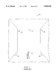
- FIG. 2 is a perspective view of a golfer using a motion measurement apparatus constructed in accordance with the present claimed invention.
- FIG. 3 is a side view of a knee joint of a golfer having a sensor attached thereto in accordance with the present claimed invention.
- FIG. 4 is a perspective view of another embodiment of the present invention in which adjacent sensors are interconnected to form a single structure in accordance with the present claimed invention.
- FIG. 5A shows a series of images duplicating the body movements of a golfer which can be displayed on a display unit while the golfer performs a golf swing in accordance with the present claimed invention.
- FIG. 5B shows a series of images duplicating the body movements of a golfer displayed wherein the images are arranged side-by-side on a display unit while the golfer performs a golf swing in accordance with the present claimed invention.
- FIG. 6A shows another embodiment of the present claimed invention in which two images having differing body positioning are displayed concurrently on a display unit in accordance with the present claimed invention.
- FIG. 6B shows the images of FIG. 6A in which the two images have the same body positioning and are displayed concurrently on a display unit in accordance with the present claimed invention.
- FIG. 6C shows a "fan" type display of the position of the golf club of a golfer and the position of the golf club of a sample golfer at different times during a golf swing in accordance with the present claimed invention.
- FIG. 7 shows another embodiment of the present claimed invention in which two images are displayed concurrently and overly each other on a display unit in accordance with the present claimed invention.
- FIG. 8A and 8B show another embodiment of the present claimed invention in which the motion measurement apparatus of the present invention is utilized by the user in conjunction with a display as a "keyboard” or “mouse” in accordance with the present claimed invention.
- FIG. 9 is a side view of a knee joint in another embodiment of the present claimed invention in which a small vibrating mechanism is attached to a sensor located on the knee joint of a golfer in accordance with the present claimed invention.
- FIGS. 10A-H are views of the structure of one embodiment of a motion measurement apparatus in accordance with the present claimed invention.
- FIG. 11A is a perspective view of an alternate arrangement of a motion measurement apparatus in accordance with the present claimed invention.
- FIG. 11B is a perspective view of an alternate embodiment of a motion measurement apparatus wherein the apparatus is used as a head mouse in accordance with the present claimed invention.
- FIG. 12 is a perspective view of an alternate embodiment of a motion measurement apparatus wherein the apparatus includes gyroscopic means in accordance with the present claimed invention.
- Prior art motion detector 10 is employed in Prior Art FIG. 1 to measure the body movements of a golfer 12 while golfer 12 performs a golf swing. As shown in Prior Art FIG. 1, prior art motion detector 10 occupies an entire room 14, and requires the use of several signal generators and detectors 16. Additionally, golfer 12 is only able to view his body movements after he has performed the golf swing and his body movements have been recorded.
- FIG. 2 a motion measurement apparatus constructed in accordance with an embodiment of the present claimed invention for measuring body movements which occur when performing a golf swing is illustrated.
- the present embodiment specifically relates to an apparatus for measuring body movements which occur while performing a golf swing
- the present claimed invention is also well suited to measuring body movements which occur while performing various other motions, such as, for example, a tennis stroke, other sports related motions, or dance movements.
- the present motion measurement invention is also well suited to incorporating the user's body motion into, for example, a video arcade game, or for converting the various movements of the user's body to corresponding musical tones.
- a golfer 20 has inexpensive and compact sensors 22 attached to his body at joints which are moved while golfer 20 performs a golf swing. Sensors 22 are attached to the joints of golfer 20 such that sensors 22 quantitatively measure the movement of the joints of golfer 20 while golfer 20 performs the golf swing. Sensors 22 are attached to joints of golfer 20 in such a manner that sensors 22 do not interfere with the movement of the joints while golfer 20 performs a golf swing.
- FIG. 3 an enlarged view of an example of a knee joint 24 of golfer 20 of FIG. 2 having a sensor 22 attached thereto is shown.
- sensor 22 is attached to knee joint 24 in a manner such that knee joint 24 is able to move without interference from sensor 22.
- rods 26 extending from sensor 22 are fastened above and below knee joint 24 using straps 28.
- sensor 22 detects the movement of rods 26 and generates an electric signal indicative of the shift in position of knee joint 24. In so doing, quantitative measurement of the movement of knee joint 24 and all other joints to which sensors 22 are attached is achieved.
- potentiometers are used as sensors 22 in the present embodiment, the present claimed invention is also well suited to the use of numerous other types of sensors well known in the art such as, for example, shaft encoders motors, optical sensors, or magnetic sensors.
- sensors 22 quantitatively measure the movement of joints in more than one dimension where needed. That is, a sensor 22 located at, for example, the elbow of golfer 20 of FIG. 2 measures both the amount of bending of the elbow and also the amount of rotation which occurs between the elbow and the wrist as golfer 20 performs a golf swing. In so doing, all of the critical body movements of golfer 20 which occur during the performance of a golf swing can be quantitatively measured by sensors 22.
- FIG. 4 another embodiment of the present claimed invention is shown in which adjacent sensors 22 are interconnected using, for example, metal tubing. That is, in the present embodiment, instead of having rods 26 of FIG. 2 strapped to the leg of golfer 20 of FIG. 2, rods 26 would extend and be attached to adjacent sensors.
- a tube 25 connects sensors 22 located at the hip and at the knee of golfer 20.
- Another tube 27 connects sensors 22 located at the ankle and knee of golfer 20.
- a single structure is formed wherein sensors 22 function as joints between connected tubes.
- a processor 30 receives and processes signals generated by each of sensors 22.
- the processed signals are then transmitted to a display unit 32.
- Display unit 32 then displays an image such as, for example, a stick figure which duplicates the body movements of golfer 20 as golfer 20 performs a golf swing. That is, display unit 32 displays in approximately real time, an image which represents the body movements of golfer 20 as golfer 20 performs a golf swing. Therefore, by placing display unit 32 within view of golfer 20, golfer 20 is able to observe his body movements, as depicted by an image on display unit 32, while golfer 20 performs a golf swing.
- processor 30 of FIG. 2 is shown located next to the body of golfer 20, processor 30 may also be contained within a small housing, not shown, and attached to the body of golfer 20 in a convenient location such as, for example, the back of golfer 20.
- FIG. 5A an example of a series of typical images which can be displayed together as a group or individually on display unit 32 are shown.
- image 40 representing a side view of golfer 20 of FIG. 2 is displayed on display unit 32.
- golfer 20 would attach sensors 22 of FIGS. 2-4 to his body and then calibrate sensors 22 and processor 30 according to the golfer's individual size and dimensions. In the present embodiment, this calibration process only needs to be performed once.
- golfer 20 would address the golf ball and observe the body position of image 40 on display unit 32. In so doing, golfer 20 would be able to observe any obvious flaws or improper body positioning occurring while golfer 20 addresses a golf ball.
- golfer 20 is able to quickly "self-correct” his golf stance and alter his body positioning until image 40 is arranged in the proper or desired position.
- golfer 20 is able to observe image 40 on display unit 32 at each moment during the golf swing and immediately recognize and correct any imperfections in his body position or his body movements. That is, the present claimed invention provides for approximate real time observation of the body movement and positioning of a golfer while the golfer is performing a golf swing.
- golfer 20 is able to receive immediate feedback and is better able to identify mistakes or imperfections in his golf swing.
- the present embodiment provides for approximate real time observation of an image representing golfer 20
- the present claimed invention is also well suited for storing the image representing the body movement and positioning of golfer 20 and displaying the image at a later time.
- golfer 20 of FIG. 2 can either view the image immediately after performing the swing or wait until a later more convenient time.
- multiple images such as, for example, images 40, 42, and 44 of golfer 20 are displayed at the same time on display unit 32.
- Images 40, 42, and 44 show the body position and movement of golfer 20 from several different angles.
- Line 48 of image 46 depicts the path of the head of the golf club just prior to and after the golf club contacts a golf ball.
- golfer 20 is able to observe his body position and movements in real time from several different angles, and golfer 20 is able to observe the path of the club head as it strikes a golf ball.
- the present embodiment employs images such as images 40, 42, 44, and 46
- the present claimed invention is also well suited to numerous other types of images which can be graphically displayed on display unit 32.
- the present claimed invention is also well suited to displaying information such as club head speed, distance that a golf ball would be hit, or other relevant information on display unit 32.
- the present invention is also well suited to displaying several images of the body position of golfer 20, wherein each of the images represents a different view of the body of golfer 20.
- a right side view 40, a front view 42, and a left side view 43 may be displayed, for example, side-by-side.
- the present invention is also well suited to displaying other views, and placing those views in different arrangements on display unit 32.
- image 50 represents the body position and body movements of golfer 20 of FIG. 2.
- Dotted image 60 represents a "sample” golfer whose body position and movements are stored in the memory of processor 30.
- Image 60 represents, for example, a stored record of the best previous golf swing of golfer 20, a golf swing of the instructor of golfer 20, a golf swing of a professional golfer, or a computer generated golf swing. Therefore, the present invention allows for real time observation by golfer 20 of his own golf swing, and also allows for real time comparison by golfer 20 of his golf swing with an "ideal" golf swing.
- golfer 20 is able to immediately alter his body position and movements during his golf swing so that his movements duplicate the body position and body movements of an ideal golfer.
- image 60 is dotted in the present embodiment, the present invention is also well suited to numerous types of image displays to differentiate image 50 from image 60, such as, for example, using different colors for images 50 and 60.
- image 60 represents an ideal golf stance
- golfer 20 of FIG. 2 would immediately be able to realize that his right shoulder is dipped too low, and that his legs are spread too far apart. Golfer 20 would then alter his stance and body position until image 50 matches image 60 as shown in FIG. 6B.
- the hands of image 50 are used as a common reference point with image 60.
- the hands of image 60 will also be at waist level.
- the rest of image 60 will then be located at the ideal position for a golfer whose hands are at waist level during a back swing.
- the hands of golfer 20 when the hands of golfer 20 are at shoulder level during a follow through, the hands of image 60 will also be at shoulder level, and golfer 20 is able to immediately determine how the rest of his body should be positioned when his hands are at shoulder level during a follow through.
- the hands are used as a common reference point in the present embodiment, the present invention is also well suited to using other portions of the golfer's body as a common reference point with image 60.
- golfer 20 of FIG. 2 can also select to have image 60 perform the ideal golf swing at several different speeds. Specifically, image 60 can perform the golf swing at a much slower rate than normal in order to allow golfer 20 time to adjust his body position and movements accordingly.
- the present invention is also well suited to having image 60 perform the golf swing at the same speed as which the sample golfer would perform the golf swing. In so doing, the present invention makes it possible for golfer 20 to observe in real time the proper tempo of an ideal golf swing. For example, if image 50 of golfer 20 has finished his swing before image 60 has completed his swing, golfer 20 knows that he must slow his swing in order to achieve an ideal tempo.
- the present invention not only provides for real time observation of body position and body movements during a golf swing, but also provides for real time observation of the tempo of a golf swing.
- FIG. 6C another embodiment of the present invention is shown in which "fan" type displays of the position 51 of the golf club of golfer 20 of FIG. 2 and the position 61 of the golf club of a sample golfer at different times during a golf swing is shown.
- "fan" type displays of the position 51 of the golf club of golfer 20 of FIG. 2 and the position 61 of the golf club of a sample golfer at different times during a golf swing is shown.
- golfer 20 is able to observe how the position 51 of his golf club differs from that of the ideal sample golfer.
- golfer 20 can observe in real time the difference in speed and tempo between his golf swing and an ideal golf swing.
- the present claimed invention is also well suited to displaying a fan type image showing the entire body or any portion thereof of golfer 20.
- image 50 represents the body position and body movements of golfer 20 of FIG. 2.
- Image 60 again represents, for example, a stored record of the best previous golf swing of golfer 20, a golf swing of the instructor of golfer 20, or a golf swing of a professional golfer whose body position and movements are stored in the memory of processor 30.
- visual cues are indicated on display unit 32.
- These visual cues include, for example, "flashing" the portions of image 50 which are positioned differently than ideal image 60. That is, the shoulders and legs of image 50 would flash to indicate to golfer 20 of FIG. 2 that his right shoulder is dipped too low and that his legs are spread too far apart.
- the flashing in the present embodiment may also be controlled such that the flashing would, for example, be more rapid the farther the improperly positioned portions of image 50 were from the desired position.
- the present invention is also well suited to various other types of visual cues such, for example color changes, or changes in the intensity of portions of image 50.
- color changes are used as the visual cue, the color of image 50 would be, for example, green when image 50 matches ideal image 60, yellow when image 50 differs slightly from the positioning of image 60, and red when image 50 greatly differs from image 60.
- the present invention also allows golfer 20 of FIG. 2 to adjust the sensitivity of the visual cues. That is, golfer 20 is able to program processor 30 of FIG. 2 to only generate a visual cue such as, for example, flashing when the positioning of any portion of image 50 varies greatly from the positioning of image 60. In so doing, if golfer 20 is a beginner, he can decrease the sensitivity of the visual cues so that he is not alerted to minute differences between image 50 and image 60. However, as the skill of golfer 20 improves, he can heighten the sensitivity of the visual cues so that he is alerted to even minor differences between the positioning of image 50 and image 60. Thus, as golfer 20 improves he can "fine tune" his golf swing to almost completely match the ideal golf swing represented by image 60.
- a visual cue such as, for example, flashing
- audible cues may include, for example, beeps or other sounds which are emitted from display unit 32 of FIG. 2 when image 50 differs from image 60. Additionally, the present invention changes the intensity or pitch of the beeps to indicate large or small variations in the position of image 50 from the position of image 60.
- FIGS. 8A and 8B another embodiment is shown in which the motion measurement apparatus of the present invention is used by golfer 20 as a "keyboard” or “mouse” in conjunction with display unit 32.
- the present invention is also well suited for use in other areas such as, for example, as a head tracking apparatus in virtual reality application.
- the present invention could also be employed as a "head mouse” for use by, for example, computer user.
- calibration means and rate control means are used to refine and translate motions of the head of a computer user to movement of, for example, a cursor or pointer on a computer screen.
- the present invention when golfer 20 raises only his left arm above his head, a predetermined function is invoked and the present invention places a specific message on display 32.
- the "Club Select" function is displayed on display unit 32 when golfer 20 raises only his left arm above his head.
- the Club Select function allows golfer 20 to indicate which club golfer 20 will be swinging by moving the position of window 68 over the desired club.
- golfer 20 may select from clubs ranging from the 1 wood (1W) to the putter (P). Although such a selection of clubs is available to golfer 20 in the present embodiment, the present invention is also well suited to numerous variations on the number or types of clubs which may be selected.
- golfer 20 moves the position of window 68 by moving his extended left arm nearer to or farther from his head.
- window 68 moves to the right or towards the putter (P) on display unit 32.
- P putter
- window 68 moves to the left or towards the one wood (1W) on display unit 32.
- FIG. 9 another embodiment of the present invention is shown in which a small vibrating mechanism 70 is attached to sensor 22 located on the knee joint 24 of golfer 20 of FIG. 2.
- Vibrator 70 is electrically coupled to processor 30 of FIG. 2. If images 50 of FIGS. 6A, 6B, and 7, differs from image 60, vibrators 70 on sensors 22 will vibrate those joints of golfer 20 which are improperly positioned. In so doing, golfer 20 is directly alerted as to which joints must be adjusted in order for image 50 to match image 60. Thus, golfer 20 is able to receive direct stimulation of his body only at those locations which are improperly positioned.
- the present invention is also well suited to the attachment of a plurality of vibrating mechanisms to the body of golfer 20.
- one vibrating mechanism may be placed at the front of knee joint 24, and a second vibrating mechanism may be located at the back of knee joint 24. If the knee of golfer 24 is bent too far, the vibrating mechanism on the front of the knee joint will be activated thereby instructing golfer 20 to straighten his knee. Likewise, if the knee of golfer 20 is too straight, the vibrating mechanism on the back of knee joint 24 will be activated thereby instructing golfer 20 to bend his knee.
- multiple vibrating mechanisms is described in the present embodiment in conjunction with knee joint 24, multiple vibrating mechanisms may be employed in various combinations at numerous joints of golfer 20.
- a vibrating mechanism is set forth in the present embodiment, the present invention is also well suited to the use of other tactile stimuli such as, for example, a mild electric shocking mechanism.
- FIG. 10A is a rear view of a right handed golfer 20, having the present invention attached to his body.
- a harness fits over the shoulders of golfer 20.
- Adjustable right and left shoulder brackets 101, 102 are attached to harness 100 using, for example, wing nuts, not shown, such that the position of right and left shoulder brackets 101, 102 may be adjusted to accommodate various shoulder widths.
- An upper back bracket 104 is also attached to harness 100 using, for example, wing nuts, not shown, such that the position of upper back bracket 104 may be adjusted to accommodate back sizes.
- a hip harness 106 is attached around the waist area of golfer.
- a lower back bracket 108 is attached to hip harness 106 using, for example, wing nuts, not shown, such that the position of lower back bracket 108 may be adjusted to accommodate various lower back sizes.
- Various potentiometers 110, 112 are coupled to upper back bracket 104.
- various potentiometers 114, 116, and 118 are disposed on lower back bracket 108.
- a telescopic sliding torque transmitting lever connector 120 couples upper back bracket 104 and lower back bracket 108.
- potentiometers 110, 112 potentiometers 114, 116, and 118, and telescopic sliding torque transmitting lever connector 120 are shown in detail.
- potentiometers 110, 112 are coupled to upper back bracket 104 using, for example, clamps 122 and 124. All of the potentiometers of the present embodiment function in a similar manner. That is, as the potentiometer is rotated about its axis, the resistance within the potentiometer is altered. As a result, the outgoing voltage varies according to the amount of rotation to which the potentiometer is subjected.
- potentiometer 110 measures the horizontal movement of the shoulders of golfer 20 of FIG. 10A with respect to the spine of golfer 20.
- Potentiometer 112 is attached to clamp 122 such that potentiometer 112 measures the front-to-back movement of the shoulders of golfer 20 with respect to the spine of golfer 20.
- Telescopic sliding torque transmitting lever connector 120 delivers torque to potentiometer 114 such that the rotation of the spine of golfer 20 is quantitatively measured.
- Potentiometer 116 is attached to clamp 126 such that potentiometer 116 measures the front-to-back tilt of the spine of golfer 20 with respect to the hips of golfer 20.
- potentiometer 118 is attached to clamp 128 in order to measure changes in the position of the hips of golfer 20 with respect to the spine of golfer 20. Specifically, potentiometer 118 measures variations from the substantially perpendicular alignment of the spine of golfer 20 to the hips of golfer 20.
- the left arm of golfer 20 also has a plurality of potentiometers 130, 131, 134, 140, 142, 148, 150, 152, clamp 132, bracket 102, harnesses 138, 146, and telescopic sliding torque transmitting lever connectors 136, 144, attached thereto.
- potentiometers 130, 131, 134, 140, 142, 148, 150, 152, clamp 132, bracket 102, harnesses 138, 146, and telescopic sliding torque transmitting lever connectors 136, 144, attached to the left arm of golfer 20 of FIG. 10A thereto is set forth.
- a potentiometer 130 is attached to clamp 132 connected to left shoulder bracket 102. Potentiometer 130 measures movement of the upper portion of the left arm of golfer 20 away from or towards the body of golfer 20.
- Potentiometer 134 measures rotational movement of the upper left arm of golfer 20.
- a telescopic sliding torque transmitting lever connector 136 is attached to potentiometer 134.
- an elbow harness 138 has a potentiometer 140 attached thereto and coupled to telescopic sliding torque transmitting lever connector 136 via a universal type joint configuration 137 in order to measure the rotation of the left upper arm of golfer 20. Additionally, elbow harness 138 has a potentiometer 142 attached thereto in order to measure the extension or bending occurring at the left elbow of golfer 20. Furthermore, one end of a telescopic sliding torque transmitting lever connector 144 is coupled to potentiometer 142 using joint 147. A wrist harness 146 is attached to the left wrist of golfer 20 and has the second end of telescopic sliding torque transmitting lever connector 144 connected to a potentiometer 148 attached thereto.
- Potentiometer 148 measures the rotation of the left wrist of golfer 20 with respect to the left elbow of golfer 20, and is coupled to potentiometer 150 which measures whether the wrist of the left hand of golfer 20 is held straight out from the lower arm or is bent up or down with respect to the lower arm of golfer 20.
- potentiometer, 152 coupled to potentiometer 150 and wrist harness 146 measures whether the wrist of golfer 20 is held straight out, is bent inward such that the thumb on the left hand approaches the inside of the lower left arm, or whether the wrist is bent outward such that the small finger of the hand is bent towards the outside of the lower left arm of golfer 20.
- FIG. 10D a view of the present invention taken along line D of FIG. 10C is shown.
- FIG. 10E a partial view of the present invention attached to the left leg of golfer 20 of FIG. 10A is shown.
- a left thigh clamp 154 is attached to lower back bracket 108.
- a potentiometer 156 measures the front-to-back motion of the left leg of golfer 20.
- Another potentiometer 158 measures the extent to which the left leg of golfer 20 is extended to the side away from the left side of golfer 20.
- a strap 160 is placed around the left knee of golfer 20.
- An elastic connector 162 extends from strap 160 to a lever arm 164.
- Lever arm 164 is coupled to a potentiometer 168 which measures the motion of the left knee of golfer 20.
- a telescopic sliding torque transmitting lever connector 170 extends downwardly from the outside of the left hip of golfer 20 towards the outside of the left ankle of golfer 20.
- a bracket 172 is attached to a left foot harness 174 worn on the left foot of golfer 20.
- Attached to bracket 172 is a potentiometer 176 for measuring whether the heel or toes of golfer 20 are pulled upward.
- Another potentiometer 178 measures the side to side motion of the foot of golfer 20. The motion of the right leg of golfer 20 is measured using a similar structure.
- the present invention is well suited to having bracket 172 coupled directly to the ground, such that the ground can be used as a reference point for the positioning of golfer 20.
- the present invention is also well suited to using means such as, for example, a gyroscope, a radio receiver, an optical system, or a magnetic link to provide a quantitative measurement of the position of golfer 20 with respect to the ground and even with respect to a golf ball or golf club.
- means such as, for example, a gyroscope, a radio receiver, an optical system, or a magnetic link to provide a quantitative measurement of the position of golfer 20 with respect to the ground and even with respect to a golf ball or golf club.
- a potentiometer 180 is coupled to right shoulder bracket 101. Potentiometer 180 measures movement of the upper portion of the right arm of golfer 20 away from or towards the body of golfer 20.
- a second potentiometer 134 measures the front-to-back motion of the right arm of golfer 20 using a lever arm 184 having an elastic band 186 attached to elbow strap 188.
- the positioning and movement of the right hand of golfer 20 on a golf club 189 is measured using a right wrist strap 190, and elastic band 192, a lever arm 194, and a potentiometer 196.
- Wrist strap 190 is connected using elastic band 192 to lever arm 194.
- Lever arm 194 is coupled to potentiometer 196 attached to golf club 189. In so doing, the movement of the right hand of golfer 20 with respect to golf club 189 is quantitatively measured.
- FIG. 11A an alternate embodiment of the present invention is shown in which an alternate arrangement of potentiometers and lever arms is used to measure the movement of a joint of golfer 20.
- sensors such as, for example, potentiometers 202 and 204 are attached to lever arms 206 and 208 respectively.
- Lever arms 206 and 208 are then respectively connected to elastic bands 210 and 212 which in turn are connected to brackets 214 and 216 respectively.
- Potentiometer 200 is also coupled to potentiometer 218 via bracket 220. Assuming that the alternate arrangement of FIG.
- potentiometer 218 measures side to side motion of golfer 20, while potentiometers 202 and 204 measure front to back motion of golfer 20.
- Rotation of the back of golfer 20 is determined by the difference between the amount of rotation recorded at potentiometers 202 and 204. For example, if potentiometer 202 measures rotation, ⁇ 202 , and potentiometer 204 measures rotation, ⁇ 204 , then the rotation of the back of golfer 20, ⁇ back , is given by ⁇ 202- ⁇ 204 .
- FIG. 11B an application of the alternate embodiment of FIG. 11A is shown.
- a head mouse 250 is shown attached to the head of a computer user 252.
- motion sensors 254, 256, and 258 are coupled to a headband 260 worn by the computer user.
- Motion sensors 254, 256, and 258 are coupled using lever arms 262 and 264, and elastic bands 266 and 268 to for example a strap 270 worn on the back of computer user 252.
- Head mouse 250 is electrically coupled to a computer 272, such that motion of the head of computer user 252 translates into motion of a cursor or pointer 274 on a computer screen 276.
- a "mouse button”, not shown, is mounted for example on a computer keyboard also not shown, for performing task associated with conventional mouses such as highlighting, dragging, and selecting, for example.
- head mouse 250 includes calibration means for initially placing cursor 274 in a desired position on computer screen 276.
- Rate control means are also provided to appropriately relate head movement of user 252 to movement of cursor 274.
- sensors 254, 256, and 258 are coupled to headband 260 in the present embodiment, the present invention is also well suited to alternate configurations including having sensors coupled, for example to the back of the chair in which the user is sitting. Additionally, the present invention is well suited to having at least one sensor positioned to measure "nodding" motions by the user. Furthermore, the present invention is also well suited to head motion measurement configurations including but not limited to using two sensors and two levers, using two sensors and one lever.
- FIG. 12 an alternate embodiment of the present invention is shown. Specifically, as described above in the discussion of FIG. 10F, a motion measurement apparatus employing gyroscopic magnetometer or other self-referencing means 300 is shown. Self-referencing means 300 are placed for example in the upper back region of golfer 20. In so doing, self-referencing means 300 is able to provide output to processor means, not shown, in order to provide a quantitative measurement of the position of golfer 20 with respect to the ground and even with respect to a golf ball or golf club.
- the present invention provides a compact, inexpensive system to monitor the movement of a human body while performing a motion such as, for example, a golf swing, which does not require the complex detection systems found in the prior art, and which provides for approximate real time observation of the body movement of a golfer while performing the golf swing. Additionally, the compact size of the present invention provides for portability which was not found in the prior art, thereby allowing the golfer to use the present invention wherever he desires.
Abstract
Description
Claims (51)
Priority Applications (5)
| Application Number | Priority Date | Filing Date | Title |
|---|---|---|---|
| US08/250,152 US5826578A (en) | 1994-05-26 | 1994-05-26 | Motion measurement apparatus |
| PCT/US1995/006626 WO1995032666A1 (en) | 1994-05-26 | 1995-05-24 | Motion measurement apparatus |
| JP50103196A JP3656853B2 (en) | 1994-05-26 | 1995-05-24 | Motion measuring device |
| US08/692,107 US5791351A (en) | 1994-05-26 | 1996-08-05 | Motion measurement apparatus |
| JP2004155169A JP2004283607A (en) | 1994-05-26 | 2004-05-25 | Exercise meter |
Applications Claiming Priority (1)
| Application Number | Priority Date | Filing Date | Title |
|---|---|---|---|
| US08/250,152 US5826578A (en) | 1994-05-26 | 1994-05-26 | Motion measurement apparatus |
Related Child Applications (1)
| Application Number | Title | Priority Date | Filing Date |
|---|---|---|---|
| US08/692,107 Continuation US5791351A (en) | 1994-05-26 | 1996-08-05 | Motion measurement apparatus |
Publications (1)
| Publication Number | Publication Date |
|---|---|
| US5826578A true US5826578A (en) | 1998-10-27 |
Family
ID=22946503
Family Applications (2)
| Application Number | Title | Priority Date | Filing Date |
|---|---|---|---|
| US08/250,152 Expired - Lifetime US5826578A (en) | 1994-05-26 | 1994-05-26 | Motion measurement apparatus |
| US08/692,107 Expired - Lifetime US5791351A (en) | 1994-05-26 | 1996-08-05 | Motion measurement apparatus |
Family Applications After (1)
| Application Number | Title | Priority Date | Filing Date |
|---|---|---|---|
| US08/692,107 Expired - Lifetime US5791351A (en) | 1994-05-26 | 1996-08-05 | Motion measurement apparatus |
Country Status (3)
| Country | Link |
|---|---|
| US (2) | US5826578A (en) |
| JP (2) | JP3656853B2 (en) |
| WO (1) | WO1995032666A1 (en) |
Cited By (178)
| Publication number | Priority date | Publication date | Assignee | Title |
|---|---|---|---|---|
| WO2000017849A1 (en) * | 1998-09-18 | 2000-03-30 | Kim Tong | Head operated computer pointer |
| US6261247B1 (en) * | 1998-12-31 | 2001-07-17 | Ball Semiconductor, Inc. | Position sensing system |
| WO2001088896A1 (en) * | 2000-05-16 | 2001-11-22 | Comsonics, Inc. | Method for utilization of a gyroscopic or inertial device as a user interface mechanism for computers |
| US20020055383A1 (en) * | 2000-02-24 | 2002-05-09 | Namco Ltd. | Game system and program |
| US20020072416A1 (en) * | 1999-06-11 | 2002-06-13 | Toshikazu Ohshima | User interface apparatus, user interface method, game apparatus, and program storage medium |
| US20020101457A1 (en) * | 2001-01-31 | 2002-08-01 | Microsoft Corporation | Bezel interface for small computing devices |
| US20020135615A1 (en) * | 2001-01-31 | 2002-09-26 | Microsoft Corporation | Overlaid display for electronic devices |
| US20020143279A1 (en) * | 2000-04-26 | 2002-10-03 | Porier David A. | Angle sensor for orthopedic rehabilitation device |
| WO2002078513A2 (en) * | 2001-03-30 | 2002-10-10 | Augmentech, Inc. | Patient incontinence/position monitoring apparatus and method of use thereof |
| US6491649B1 (en) | 2000-10-06 | 2002-12-10 | Mark P. Ombrellaro | Device for the direct manual examination of a patient in a non-contiguous location |
| US6514081B1 (en) * | 1999-08-06 | 2003-02-04 | Jeffrey L. Mengoli | Method and apparatus for automating motion analysis |
| US20030036436A1 (en) * | 2000-12-01 | 2003-02-20 | Casanova Manuel M. | Grip pressure detector assembly |
| US20030040380A1 (en) * | 2001-04-05 | 2003-02-27 | Wright Ian C. | Method for matching a golfer with a particular golf club style |
| US6533675B2 (en) * | 2001-06-11 | 2003-03-18 | Conley Jack Funk | Interactive method and apparatus for tracking and analyzing a golf swing |
| US20030109322A1 (en) * | 2001-06-11 | 2003-06-12 | Funk Conley Jack | Interactive method and apparatus for tracking and analyzing a golf swing in a limited space with swing position recognition and reinforcement |
| US20030113694A1 (en) * | 2001-12-18 | 2003-06-19 | Develop Your Game, Inc. | Data processing method and system for processing and managing repetitive motion data between diverse geographic locations |
| US20030134259A1 (en) * | 2001-11-20 | 2003-07-17 | Tony Adams | Method of teaching through exposure to relevant perspective |
| EP1331024A1 (en) * | 2002-01-29 | 2003-07-30 | Konami Corporation | Exercise recording system, exercise recording device and recording medium having the computer program for exercise recording system recorded thereon |
| WO2003067973A1 (en) * | 2002-02-13 | 2003-08-21 | Tokyo University Of Agriculture And Technology Tlo Co., Ltd. | Automatic animal motion observation method and apparatus, and motion quantization apparatus |
| US6610011B2 (en) * | 2000-12-27 | 2003-08-26 | Siemens Medical Solutions Usa, Inc. | Method and system for control of probe heating using lens reflection pulse-echo feedback |
| US20030160693A1 (en) * | 2002-02-25 | 2003-08-28 | Omron Corporation | Status monitoring system employing a movement history and a self-organizing network |
| US20030160695A1 (en) * | 2002-02-25 | 2003-08-28 | Omron Corporation | Identification and surveillance systems for freight container, and method for the same |
| US20030164763A1 (en) * | 2002-02-25 | 2003-09-04 | Omron Corporation | State surveillance system and method for an object and the adjacent space, and a surveillance system for freight containers |
| US6663491B2 (en) * | 2000-02-18 | 2003-12-16 | Namco Ltd. | Game apparatus, storage medium and computer program that adjust tempo of sound |
| US20040027455A1 (en) * | 2000-12-15 | 2004-02-12 | Leonard Reiffel | Imaged coded data source tracking product |
| US6699138B1 (en) * | 2000-12-13 | 2004-03-02 | Teh-Cheng Lin | Golf swing indication device |
| US20040041027A1 (en) * | 2000-12-15 | 2004-03-04 | Leonard Reiffel | Imaged coded data source transducer product |
| US20040077975A1 (en) * | 2002-10-22 | 2004-04-22 | Zimmerman Jeffrey C. | Systems and methods for motion analysis and feedback |
| US20040083528A1 (en) * | 2002-10-11 | 2004-05-06 | Stewart Robert E. | Employment of one or more signals based on one or more joint motions of an individual to make a determination of a positional change of the individual |
| US6738516B1 (en) * | 1998-06-18 | 2004-05-18 | Minolta Co., Ltd. | Monitor display apparatus |
| US20040097836A1 (en) * | 2000-10-06 | 2004-05-20 | Ombrellaro Mark P. | Direct manual examination of remote patient with virtual examination functionality |
| US6746247B2 (en) | 2000-12-27 | 2004-06-08 | Michael P. Barton | Choreographed athletic movement to music |
| US20040121849A1 (en) * | 2002-12-18 | 2004-06-24 | Curkovic Joseph A. | Golf swing aid |
| WO2004054662A1 (en) * | 2002-12-18 | 2004-07-01 | Swingscope Inc. | Golf swing aid |
| US20040125224A1 (en) * | 2000-08-18 | 2004-07-01 | Leonard Reiffel | Annotating imaged data product |
| US20040135766A1 (en) * | 2001-08-15 | 2004-07-15 | Leonard Reiffel | Imaged toggled data input product |
| US6793585B1 (en) * | 1999-10-19 | 2004-09-21 | Yokohama Rubber Co., Ltd. | Swing measurement method, golf swing analysis method, and computer program product |
| WO2004084725A1 (en) * | 2003-03-26 | 2004-10-07 | Neopraxis Pty Ltd | Motion analysis system and method |
| US20040209698A1 (en) * | 2003-04-16 | 2004-10-21 | Masahiko Ueda | Golf swing diagnosis system |
| US20040219498A1 (en) * | 2002-04-09 | 2004-11-04 | Davidson Lance Samuel | Training apparatus and methods |
| US20040239491A1 (en) * | 2003-05-27 | 2004-12-02 | Koutsky L. John | Vehicle seat with vibration monitoring ability |
| US20050032582A1 (en) * | 2002-12-19 | 2005-02-10 | Satayan Mahajan | Method and apparatus for determining orientation and position of a moveable object |
| US20050102332A1 (en) * | 2000-12-15 | 2005-05-12 | Leonard Reiffel | Multi-imager multi-source multi-use coded data source data iInput product |
| US20050124919A1 (en) * | 2003-12-03 | 2005-06-09 | Castillo James D. | Measuring device |
| US6909420B1 (en) * | 1998-12-03 | 2005-06-21 | Nicolas Frederic | Device indicating movements for software |
| US20050149364A1 (en) * | 2000-10-06 | 2005-07-07 | Ombrellaro Mark P. | Multifunction telemedicine software with integrated electronic medical record |
| US20050203443A1 (en) * | 2003-03-15 | 2005-09-15 | Salvi Frank J. | Apparatus and method for measuring and monitoring range of motion of the lumbar spine |
| US20050215336A1 (en) * | 2004-03-26 | 2005-09-29 | Sumitomo Rubber Industries, Ltd. | Golf swing-diagnosing system |
| US20060025229A1 (en) * | 2003-12-19 | 2006-02-02 | Satayan Mahajan | Motion tracking and analysis apparatus and method and system implementations thereof |
| US7000840B2 (en) | 2000-05-03 | 2006-02-21 | Leonard Reiffel | Dual mode data imaging product |
| US7018211B1 (en) * | 1998-08-31 | 2006-03-28 | Siemens Aktiengesellschaft | System for enabling a moving person to control body movements to be performed by said person |
| US20060084516A1 (en) * | 2004-07-28 | 2006-04-20 | Smartswing, Inc. | Method and system for defining and using a reference swing for a sports training system |
| US7034803B1 (en) | 2000-08-18 | 2006-04-25 | Leonard Reiffel | Cursor display privacy product |
| US20060090548A1 (en) * | 2004-10-28 | 2006-05-04 | Kostuj William A | Waggle weight |
| US20060121419A1 (en) * | 2004-12-03 | 2006-06-08 | Virtra Systems, Inc. | Threat fire simulation system |
| KR20060066261A (en) * | 2004-12-13 | 2006-06-16 | 엘지전자 주식회사 | Apparatus and method for act cognition by using mobile communication station and motion capture |
| US20060141434A1 (en) * | 2003-01-21 | 2006-06-29 | Moran Jr Thomas F | Training device for golf swing and similar motions |
| US7074168B1 (en) | 2001-08-10 | 2006-07-11 | Farnes Larry D | System for human physical evaluation and accomplish improved physical performance |
| US20060202997A1 (en) * | 2005-03-10 | 2006-09-14 | Lavalley Zachery | Apparatus, system and method for interpreting and reproducing physical motion |
| US7137711B1 (en) | 2000-03-21 | 2006-11-21 | Leonard Reiffel | Multi-user retro reflector data input |
| US20060287118A1 (en) * | 2001-04-06 | 2006-12-21 | Taylor Made Golf Company, Inc. | Method for matching a golfer with a particular club style |
| US20060291797A1 (en) * | 2003-05-27 | 2006-12-28 | Leonard Reiffel | Multi-imager multi-source multi-use coded data source data input product |
| US20070187506A1 (en) * | 2001-04-19 | 2007-08-16 | Leonard Reiffel | Combined imaging coded data source data acquisition |
| US20070270214A1 (en) * | 2005-01-26 | 2007-11-22 | Bentley Kinetics, Inc. | Method and system for athletic motion analysis and instruction |
| US20070283966A1 (en) * | 2006-06-09 | 2007-12-13 | Maples Paul D | Contamination avoiding device |
| US20080036737A1 (en) * | 2006-08-13 | 2008-02-14 | Hernandez-Rebollar Jose L | Arm Skeleton for Capturing Arm Position and Movement |
| US20080091373A1 (en) * | 2006-07-31 | 2008-04-17 | University Of New Brunswick | Method for calibrating sensor positions in a human movement measurement and analysis system |
| US20080287204A1 (en) * | 2007-05-15 | 2008-11-20 | United States Bowling Congress, Inc. | System and method for analyzing bowling ball motion |
| US20080293465A1 (en) * | 2007-05-25 | 2008-11-27 | Hong Chang | Video interaction device for a whole-body sport game |
| US20090017930A1 (en) * | 2007-07-11 | 2009-01-15 | Acushnet Company | Method for measuring golf swing efficiency |
| US20090033770A1 (en) * | 2007-07-31 | 2009-02-05 | Johnson Paul R | Systems and Methods of Monitoring Exercises and Ranges of Motion |
| US20090082701A1 (en) * | 2007-03-07 | 2009-03-26 | Motek Bv | Method for real time interactive visualization of muscle forces and joint torques in the human body |
| US20090220124A1 (en) * | 2008-02-29 | 2009-09-03 | Fred Siegel | Automated scoring system for athletics |
| US7602301B1 (en) | 2006-01-09 | 2009-10-13 | Applied Technology Holdings, Inc. | Apparatus, systems, and methods for gathering and processing biometric and biomechanical data |
| US20090270193A1 (en) * | 2008-04-24 | 2009-10-29 | United States Bowling Congress | Analyzing a motion of a bowler |
| US20100023314A1 (en) * | 2006-08-13 | 2010-01-28 | Jose Hernandez-Rebollar | ASL Glove with 3-Axis Accelerometers |
| US20100063794A1 (en) * | 2003-08-28 | 2010-03-11 | Hernandez-Rebollar Jose L | Method and apparatus for translating hand gestures |
| US20100131113A1 (en) * | 2007-05-03 | 2010-05-27 | Motek Bv | Method and system for real time interactive dynamic alignment of prosthetics |
| US20100173276A1 (en) * | 2007-06-18 | 2010-07-08 | Maxim Alexeevich Vasin | Training method and a device for carrying out said method |
| US7789742B1 (en) * | 1999-05-12 | 2010-09-07 | Wilbert Q. Murdock | Smart golf club multiplayer system for the internet |
| US20100228158A1 (en) * | 2009-03-05 | 2010-09-09 | Searete Llc, A Limited Liability Corporation Of The State Of Delaware | Postural information system and method including device level determining of subject advisory information based on subject status information and postural influencer status information |
| US20110130214A1 (en) * | 2009-12-01 | 2011-06-02 | A School Corporation Kansai University | Method for designing golf club and golf club |
| US20110140929A1 (en) * | 2009-12-14 | 2011-06-16 | Empire Technology Development Llc | Apparatus for analyzing operations and method for analyzing operations |
| US7989689B2 (en) * | 1996-07-10 | 2011-08-02 | Bassilic Technologies Llc | Electronic music stand performer subsystems and music communication methodologies |
| US20110207560A1 (en) * | 2001-04-05 | 2011-08-25 | Taylor Made Golf Company, Inc. | Method for matching a golfer with a particular golf club style |
| US20110300948A1 (en) * | 2008-12-16 | 2011-12-08 | Masashi Takehiro | Game device, game processing method, information recording medium, and program |
| DE102011009952A1 (en) * | 2011-02-01 | 2012-08-02 | Deutsches Zentrum für Luft- und Raumfahrt e.V. | Method for determining position and location of astronaut in spacecraft, involves transmitting three-dimensional co-ordinates of detected three-dimensional position of each point from spacecraft to control station |
| US20120215134A1 (en) * | 2007-03-19 | 2012-08-23 | Nicholas Hunter-Jones | Skin Elasticity Measurement |
| US8267691B1 (en) * | 2004-12-03 | 2012-09-18 | Vitra Systems, Inc. | Threat fire simulation and training system |
| WO2013040424A1 (en) * | 2011-09-14 | 2013-03-21 | Cornell University | System and methods for evaluating and providing feedback regarding movement of a subject |
| US20130115583A1 (en) * | 2011-11-07 | 2013-05-09 | Nike, Inc. | User interface for remote joint workout session |
| US8465376B2 (en) | 2010-08-26 | 2013-06-18 | Blast Motion, Inc. | Wireless golf club shot count system |
| US8503086B2 (en) | 1995-11-06 | 2013-08-06 | Impulse Technology Ltd. | System and method for tracking and assessing movement skills in multidimensional space |
| US20130305806A1 (en) * | 2012-05-21 | 2013-11-21 | Takashi Saito | Golf swing measurement system, measurement apparatus, and measurement method |
| US20130324279A1 (en) * | 2011-01-28 | 2013-12-05 | Korea Institute Of Science And Technology | System and method for posture correcting |
| US20140018704A1 (en) * | 2012-07-12 | 2014-01-16 | The Trustees Of The Stevens Institute Of Technology | Tri-axial electro-goniometer for spinal motion, associated system and methods |
| US20140024981A1 (en) * | 2012-07-23 | 2014-01-23 | Korea Institute Of Science And Technology | Wearable vibratory stimulation device and operational protocol thereof |
| US8692099B2 (en) | 1996-07-10 | 2014-04-08 | Bassilic Technologies Llc | System and methodology of coordinated collaboration among users and groups |
| US8700354B1 (en) | 2013-06-10 | 2014-04-15 | Blast Motion Inc. | Wireless motion capture test head system |
| US8702516B2 (en) | 2010-08-26 | 2014-04-22 | Blast Motion Inc. | Motion event recognition system and method |
| US20140213415A1 (en) * | 2010-01-08 | 2014-07-31 | Kermit Patrick Parker | Digital professional training instructor (The DPT instructor) |
| US8827824B2 (en) | 2010-08-26 | 2014-09-09 | Blast Motion, Inc. | Broadcasting system for broadcasting images with augmented motion data |
| US8903521B2 (en) | 2010-08-26 | 2014-12-02 | Blast Motion Inc. | Motion capture element |
| US8905855B2 (en) | 2010-08-26 | 2014-12-09 | Blast Motion Inc. | System and method for utilizing motion capture data |
| US8913134B2 (en) | 2012-01-17 | 2014-12-16 | Blast Motion Inc. | Initializing an inertial sensor using soft constraints and penalty functions |
| US8941723B2 (en) | 2010-08-26 | 2015-01-27 | Blast Motion Inc. | Portable wireless mobile device motion capture and analysis system and method |
| US8944928B2 (en) | 2010-08-26 | 2015-02-03 | Blast Motion Inc. | Virtual reality system for viewing current and previously stored or calculated motion data |
| US8994826B2 (en) | 2010-08-26 | 2015-03-31 | Blast Motion Inc. | Portable wireless mobile device motion capture and analysis system and method |
| US20150111657A1 (en) * | 2013-10-18 | 2015-04-23 | Seiko Epson Corporation | Movement analysis method, movement analysis apparatus, and movement analysis program |
| US9033810B2 (en) | 2010-08-26 | 2015-05-19 | Blast Motion Inc. | Motion capture element mount |
| US9039527B2 (en) | 2010-08-26 | 2015-05-26 | Blast Motion Inc. | Broadcasting method for broadcasting images with augmented motion data |
| US9076041B2 (en) | 2010-08-26 | 2015-07-07 | Blast Motion Inc. | Motion event recognition and video synchronization system and method |
| US20150283428A1 (en) * | 2013-02-15 | 2015-10-08 | Seiko Epson Corporation | Motion analysis system and azimuth tuning method |
| US9235765B2 (en) | 2010-08-26 | 2016-01-12 | Blast Motion Inc. | Video and motion event integration system |
| US9247212B2 (en) | 2010-08-26 | 2016-01-26 | Blast Motion Inc. | Intelligent motion capture element |
| US9254430B2 (en) | 2014-04-03 | 2016-02-09 | Anthony LaSala | Golf backswing training aid and alert |
| US9261526B2 (en) | 2010-08-26 | 2016-02-16 | Blast Motion Inc. | Fitting system for sporting equipment |
| US20160049089A1 (en) * | 2013-03-13 | 2016-02-18 | James Witt | Method and apparatus for teaching repetitive kinesthetic motion |
| US9268406B2 (en) | 2011-09-30 | 2016-02-23 | Microsoft Technology Licensing, Llc | Virtual spectator experience with a personal audio/visual apparatus |
| US9286711B2 (en) | 2011-09-30 | 2016-03-15 | Microsoft Technology Licensing, Llc | Representing a location at a previous time period using an augmented reality display |
| US9320957B2 (en) | 2010-08-26 | 2016-04-26 | Blast Motion Inc. | Wireless and visual hybrid motion capture system |
| US9345957B2 (en) | 2011-09-30 | 2016-05-24 | Microsoft Technology Licensing, Llc | Enhancing a sport using an augmented reality display |
| US20160194100A1 (en) * | 2013-09-20 | 2016-07-07 | Ishida Co., Ltd. | Packaging machine |
| US9396385B2 (en) | 2010-08-26 | 2016-07-19 | Blast Motion Inc. | Integrated sensor and video motion analysis method |
| US9401178B2 (en) | 2010-08-26 | 2016-07-26 | Blast Motion Inc. | Event analysis system |
| US9406336B2 (en) | 2010-08-26 | 2016-08-02 | Blast Motion Inc. | Multi-sensor event detection system |
| US9418705B2 (en) | 2010-08-26 | 2016-08-16 | Blast Motion Inc. | Sensor and media event detection system |
| US20160284231A1 (en) * | 2015-03-26 | 2016-09-29 | President And Fellows Of Harvard College | Systems and Methods for Detecting Overstriding in Runners |
| US9457256B2 (en) | 2010-11-05 | 2016-10-04 | Nike, Inc. | Method and system for automated personal training that includes training programs |
| US9604142B2 (en) | 2010-08-26 | 2017-03-28 | Blast Motion Inc. | Portable wireless mobile device motion capture data mining system and method |
| US9606992B2 (en) | 2011-09-30 | 2017-03-28 | Microsoft Technology Licensing, Llc | Personal audio/visual apparatus providing resource management |
| US9607652B2 (en) | 2010-08-26 | 2017-03-28 | Blast Motion Inc. | Multi-sensor event detection and tagging system |
| US9619891B2 (en) | 2010-08-26 | 2017-04-11 | Blast Motion Inc. | Event analysis and tagging system |
| US9622361B2 (en) | 2010-08-26 | 2017-04-11 | Blast Motion Inc. | Enclosure and mount for motion capture element |
| US9626554B2 (en) | 2010-08-26 | 2017-04-18 | Blast Motion Inc. | Motion capture system that combines sensors with different measurement ranges |
| US9646209B2 (en) | 2010-08-26 | 2017-05-09 | Blast Motion Inc. | Sensor and media event detection and tagging system |
| US9643049B2 (en) | 2010-08-26 | 2017-05-09 | Blast Motion Inc. | Shatter proof enclosure and mount for a motion capture element |
| US20170157464A1 (en) * | 2014-03-28 | 2017-06-08 | Seiko Epson Corporation | Information providing method, information providing device, information providing system, and information providing program |
| US9694267B1 (en) | 2016-07-19 | 2017-07-04 | Blast Motion Inc. | Swing analysis method using a swing plane reference frame |
| US9746354B2 (en) | 2010-08-26 | 2017-08-29 | Blast Motion Inc. | Elastomer encased motion sensor package |
| US9811639B2 (en) | 2011-11-07 | 2017-11-07 | Nike, Inc. | User interface and fitness meters for remote joint workout session |
| US9852271B2 (en) | 2010-12-13 | 2017-12-26 | Nike, Inc. | Processing data of a user performing an athletic activity to estimate energy expenditure |
| US9919186B2 (en) | 2010-11-05 | 2018-03-20 | Nike, Inc. | Method and system for automated personal training |
| US9940508B2 (en) | 2010-08-26 | 2018-04-10 | Blast Motion Inc. | Event detection, confirmation and publication system that integrates sensor data and social media |
| US20180193712A1 (en) * | 2015-06-29 | 2018-07-12 | Université De Bordeaux | Device for board sports and associated learning method |
| US10124230B2 (en) | 2016-07-19 | 2018-11-13 | Blast Motion Inc. | Swing analysis method using a sweet spot trajectory |
| US20180345075A1 (en) * | 2017-05-30 | 2018-12-06 | Under Armour, Inc. | Techniques for Evaluating Swing Metrics |
| US10188930B2 (en) | 2012-06-04 | 2019-01-29 | Nike, Inc. | Combinatory score having a fitness sub-score and an athleticism sub-score |
| US10254139B2 (en) | 2010-08-26 | 2019-04-09 | Blast Motion Inc. | Method of coupling a motion sensor to a piece of equipment |
| US20190105547A1 (en) * | 2017-10-09 | 2019-04-11 | Martin Wyeth | Apparatus and method for repetitive training of golf swing |
| US10265602B2 (en) | 2016-03-03 | 2019-04-23 | Blast Motion Inc. | Aiming feedback system with inertial sensors |
| US10420982B2 (en) | 2010-12-13 | 2019-09-24 | Nike, Inc. | Fitness training system with energy expenditure calculation that uses a form factor |
| US10583328B2 (en) | 2010-11-05 | 2020-03-10 | Nike, Inc. | Method and system for automated personal training |
| US10786181B1 (en) | 2019-07-23 | 2020-09-29 | John D Echols | Goniometer |
| US10786728B2 (en) | 2017-05-23 | 2020-09-29 | Blast Motion Inc. | Motion mirroring system that incorporates virtual environment constraints |
| US10814491B2 (en) | 2017-10-06 | 2020-10-27 | Synaptive Medical (Barbados) Inc. | Wireless hands-free pointer system |
| US10843332B2 (en) | 2013-05-31 | 2020-11-24 | President And Fellow Of Harvard College | Soft exosuit for assistance with human motion |
| US10864100B2 (en) | 2014-04-10 | 2020-12-15 | President And Fellows Of Harvard College | Orthopedic device including protruding members |
| US11000944B2 (en) * | 2015-04-22 | 2021-05-11 | Massachusetts Institute Of Technology | Foot touch position following apparatus, method of controlling movement thereof, and non-transitory computer-readable information recording medium storing the same |
| US11014804B2 (en) | 2017-03-14 | 2021-05-25 | President And Fellows Of Harvard College | Systems and methods for fabricating 3D soft microstructures |
| US11033776B2 (en) | 2005-01-26 | 2021-06-15 | K-Motion Interactive, Inc. | Method and system for athletic motion analysis and instruction |
| USD928635S1 (en) * | 2019-09-18 | 2021-08-24 | Rom Technologies, Inc. | Goniometer |
| US11117033B2 (en) | 2010-04-26 | 2021-09-14 | Wilbert Quinc Murdock | Smart system for display of dynamic movement parameters in sports and training |
| US11133096B2 (en) * | 2011-08-08 | 2021-09-28 | Smith & Nephew, Inc. | Method for non-invasive motion tracking to augment patient administered physical rehabilitation |
| US20220054920A1 (en) * | 2019-03-04 | 2022-02-24 | Pd Golf Llc, A Texas Limited Liability Company | System and method for detecting lower body positions, movements, and sequence in golf swing training |
| US11324655B2 (en) | 2013-12-09 | 2022-05-10 | Trustees Of Boston University | Assistive flexible suits, flexible suit systems, and methods for making and control thereof to assist human mobility |
| US11464700B2 (en) | 2012-09-17 | 2022-10-11 | President And Fellows Of Harvard College | Soft exosuit for assistance with human motion |
| US11498203B2 (en) | 2016-07-22 | 2022-11-15 | President And Fellows Of Harvard College | Controls optimization for wearable systems |
| US11565163B2 (en) | 2015-07-16 | 2023-01-31 | Blast Motion Inc. | Equipment fitting system that compares swing metrics |
| US11577142B2 (en) | 2015-07-16 | 2023-02-14 | Blast Motion Inc. | Swing analysis system that calculates a rotational profile |
| US11590046B2 (en) | 2016-03-13 | 2023-02-28 | President And Fellows Of Harvard College | Flexible members for anchoring to the body |
| US11599257B2 (en) * | 2019-11-12 | 2023-03-07 | Cast Group Of Companies Inc. | Electronic tracking device and charging apparatus |
| US11673024B2 (en) | 2018-01-22 | 2023-06-13 | Pg Tech, Llc | Method and system for human motion analysis and instruction |
| US11691051B1 (en) * | 2022-07-26 | 2023-07-04 | PD Golf LLC | Golf swing training device |
| US11833406B2 (en) | 2015-07-16 | 2023-12-05 | Blast Motion Inc. | Swing quality measurement system |
| US11832934B1 (en) * | 2020-05-04 | 2023-12-05 | Qingbin Zheng | Joint monitoring |
| US11879959B2 (en) | 2019-05-13 | 2024-01-23 | Cast Group Of Companies Inc. | Electronic tracking device and related system |
| US11944428B2 (en) | 2015-11-30 | 2024-04-02 | Nike, Inc. | Apparel with ultrasonic position sensing and haptic feedback for activities |
Families Citing this family (56)
| Publication number | Priority date | Publication date | Assignee | Title |
|---|---|---|---|---|
| ATE468071T1 (en) * | 1996-07-18 | 2010-06-15 | Donald B Curchod | MOTION MEASUREMENT DEVICE |
| JP2917973B2 (en) * | 1997-06-23 | 1999-07-12 | 日本電気株式会社 | Simulated bodily sensation device |
| DE29719250U1 (en) * | 1997-10-30 | 1998-05-07 | Hauptverband Der Gewerblichen | Body stress measurement and analysis system |
| US20070177804A1 (en) * | 2006-01-30 | 2007-08-02 | Apple Computer, Inc. | Multi-touch gesture dictionary |
| WO2000053272A2 (en) * | 1999-03-11 | 2000-09-14 | Marlo Wandel | Method of diagnosing a golf swing |
| JP3824462B2 (en) * | 2000-02-24 | 2006-09-20 | 株式会社バンダイナムコゲームス | GAME DEVICE AND INFORMATION STORAGE MEDIUM |
| JP2002210055A (en) * | 2001-01-17 | 2002-07-30 | Saibuaasu:Kk | Swing measuring system |
| JP4727071B2 (en) * | 2001-06-18 | 2011-07-20 | 株式会社日清製粉グループ本社 | Craftsmanship reproduction system |
| DE60327073D1 (en) * | 2002-02-07 | 2009-05-20 | Ecole Polytech | BODY MOVEMENT MONITOR |
| JP2004024627A (en) * | 2002-06-26 | 2004-01-29 | Yamaha Corp | Device for movement practice |
| ITMI20032126A1 (en) * | 2003-11-04 | 2005-05-05 | Bonardi Fiorenzo | SYSTEM FOR THE EXECUTION OF ARTICULAR MOVEMENTS INDUCED WITH HIGH EFFICIENCY, PARTICULARLY FOR REHABILITATION, SPORTS AND SIMILAR PURPOSES |
| WO2005119356A2 (en) | 2004-05-28 | 2005-12-15 | Erik Jan Banning | Interactive direct-pointing system and calibration method |
| JP4646209B2 (en) * | 2005-02-23 | 2011-03-09 | 日本ナレッジ株式会社 | Practical skill analysis system and program |
| US7412904B2 (en) * | 2005-04-05 | 2008-08-19 | Holder Thomas L | Isokinetic testing apparatus and system |
| US7314437B2 (en) * | 2005-04-07 | 2008-01-01 | Acceleration Products, Inc. | Training harness for athletic hitting and swinging skills |
| TW200639405A (en) * | 2005-05-13 | 2006-11-16 | Ind Tech Res Inst | Interactive system with motion sensing capability |
| WO2007008165A1 (en) * | 2005-07-08 | 2007-01-18 | Skipper International Ab | Feedback training device |
| US7383728B2 (en) | 2005-07-13 | 2008-06-10 | Ultimate Balance, Inc. | Orientation and motion sensing in athletic training systems, physical rehabilitation and evaluation systems, and hand-held devices |
| US9285897B2 (en) | 2005-07-13 | 2016-03-15 | Ultimate Pointer, L.L.C. | Easily deployable interactive direct-pointing system and calibration method therefor |
| JP4752052B2 (en) * | 2005-07-15 | 2011-08-17 | 国立大学法人広島大学 | Knee joint motion measuring device |
| KR100722870B1 (en) * | 2005-11-28 | 2007-05-30 | 유인자 | Arranging apparatus of destination line in golf and golf putter |
| US7771318B2 (en) * | 2005-12-22 | 2010-08-10 | International Business Machines Corporation | Device for monitoring a user's posture |
| JP3926830B2 (en) * | 2006-03-29 | 2007-06-06 | 株式会社バンダイナムコゲームス | GAME DEVICE AND INFORMATION STORAGE MEDIUM |
| US9311528B2 (en) * | 2007-01-03 | 2016-04-12 | Apple Inc. | Gesture learning |
| US7942785B1 (en) | 2007-08-06 | 2011-05-17 | Russell Lori E | Joint range of motion measurement device and mobility enhancer |
| JP4840510B2 (en) * | 2007-09-28 | 2011-12-21 | パナソニック電工株式会社 | Exercise system |
| JP4844675B2 (en) * | 2007-09-28 | 2011-12-28 | パナソニック電工株式会社 | Exercise system |
| US8413075B2 (en) * | 2008-01-04 | 2013-04-02 | Apple Inc. | Gesture movies |
| CN101983090A (en) * | 2008-04-03 | 2011-03-02 | 韩国电子通信研究院 | Training apparatus and method based on motion content |
| JP2009277195A (en) * | 2008-04-18 | 2009-11-26 | Panasonic Electric Works Co Ltd | Information display system |
| US8444564B2 (en) * | 2009-02-02 | 2013-05-21 | Jointvue, Llc | Noninvasive diagnostic system |
| US8517834B2 (en) * | 2009-02-17 | 2013-08-27 | Softkinetic Studios Sa | Computer videogame system with body position detector that requires user to assume various body positions |
| WO2010099361A1 (en) * | 2009-02-25 | 2010-09-02 | Sherlock Nmd, Llc | Devices, systems and methods for capturing biomechanical motion |
| US20100305480A1 (en) * | 2009-06-01 | 2010-12-02 | Guoyi Fu | Human Motion Classification At Cycle Basis Of Repetitive Joint Movement |
| JP5540583B2 (en) * | 2009-06-24 | 2014-07-02 | 富士ゼロックス株式会社 | POSITION MEASUREMENT SYSTEM, POSITION MEASUREMENT COMPUTER AND PROGRAM |
| GB2474852A (en) * | 2009-10-27 | 2011-05-04 | Ali Kord | A motion capture suit |
| IT1399855B1 (en) * | 2010-04-28 | 2013-05-09 | Technogym Spa | APPARATUS FOR THE ASSISTED EXECUTION OF A GYMNASTIC EXERCISE. |
| US9223936B2 (en) | 2010-11-24 | 2015-12-29 | Nike, Inc. | Fatigue indices and uses thereof |
| JP5660608B2 (en) * | 2010-11-26 | 2015-01-28 | 国立大学法人 千葉大学 | Dynamic knee joint diagnosis device |
| US8771206B2 (en) * | 2011-08-19 | 2014-07-08 | Accenture Global Services Limited | Interactive virtual care |
| DE102012101152C5 (en) | 2012-02-14 | 2019-02-14 | Pixformance Sports Gmbh | System and method for automatically controlling the correct performance of a fitness exercise |
| WO2015172096A1 (en) * | 2014-05-09 | 2015-11-12 | Arizona Board Of Regents On Behalf Of Arizona State University | Repetitive motion injury warning system and method |
| JP6583605B2 (en) * | 2014-12-12 | 2019-10-02 | カシオ計算機株式会社 | Exercise information generation apparatus, exercise information generation method, and exercise information generation program |
| JP6127078B2 (en) * | 2015-02-17 | 2017-05-10 | 日本電信電話株式会社 | Exercise state and psychological state determination method, apparatus, and program |
| JP6093787B2 (en) * | 2015-02-17 | 2017-03-08 | 日本電信電話株式会社 | Feedback method, system, and program for exercise state and psychological state |
| JP6431785B2 (en) * | 2015-02-17 | 2018-11-28 | 日本電信電話株式会社 | Psychological state feedback method, system, and program |
| GB2537644A (en) * | 2015-04-22 | 2016-10-26 | Tintro Ltd | Electronic equipment for the treatment and care of living beings |
| US10559214B2 (en) * | 2015-09-25 | 2020-02-11 | International Business Machines Corporation | Providing live feedback using a wearable computing device |
| JP2017080198A (en) * | 2015-10-29 | 2017-05-18 | キヤノンマーケティングジャパン株式会社 | Information processing device, information processing method, and program |
| WO2017118939A1 (en) * | 2016-01-07 | 2017-07-13 | Shrivastava Harshit | Intent based inputs and forced feedback system for a virtual reality system |
| KR101795474B1 (en) * | 2016-06-03 | 2017-11-10 | 조선대학교산학협력단 | Golf posture correction method and golf posture correction system using the same. |
| JP6435302B2 (en) * | 2016-10-17 | 2018-12-05 | 日本電信電話株式会社 | Exercise state and psychological state determination method, apparatus, and program |
| JP6934659B2 (en) * | 2017-06-21 | 2021-09-15 | 株式会社岩田鉄工所 | Motion detection device |
| CO2018011434A1 (en) * | 2018-10-25 | 2020-05-05 | Isern Juan Cruz Tabena | Flexion indicating device for a joint |
| KR102379604B1 (en) * | 2020-05-28 | 2022-03-28 | 박정민 | Swing analysis apparatus |
| WO2023118978A1 (en) * | 2021-12-22 | 2023-06-29 | Давит АРСЕНЯН | Intelligent gait simulator |
Citations (4)
| Publication number | Priority date | Publication date | Assignee | Title |
|---|---|---|---|---|
| US4665928A (en) * | 1983-08-10 | 1987-05-19 | Orthotronics, Inc. | Range of motion measuring and displaying device |
| US4891748A (en) * | 1986-05-30 | 1990-01-02 | Mann Ralph V | System and method for teaching physical skills |
| US4912638A (en) * | 1987-05-04 | 1990-03-27 | Pratt Jr G Andrew | Biofeedback lifting monitor |
| US5249967A (en) * | 1991-07-12 | 1993-10-05 | George P. O'Leary | Sports technique video training device |
Family Cites Families (2)
| Publication number | Priority date | Publication date | Assignee | Title |
|---|---|---|---|---|
| JPS59225082A (en) * | 1983-06-03 | 1984-12-18 | 湯原 光保 | Swing dyagnostic apparatus |
| US4839809A (en) * | 1987-08-04 | 1989-06-13 | Leighton Stephen B | Magnetic personal turning monitor |
-
1994
- 1994-05-26 US US08/250,152 patent/US5826578A/en not_active Expired - Lifetime
-
1995
- 1995-05-24 JP JP50103196A patent/JP3656853B2/en not_active Expired - Fee Related
- 1995-05-24 WO PCT/US1995/006626 patent/WO1995032666A1/en active Search and Examination
-
1996
- 1996-08-05 US US08/692,107 patent/US5791351A/en not_active Expired - Lifetime
-
2004
- 2004-05-25 JP JP2004155169A patent/JP2004283607A/en active Pending
Patent Citations (4)
| Publication number | Priority date | Publication date | Assignee | Title |
|---|---|---|---|---|
| US4665928A (en) * | 1983-08-10 | 1987-05-19 | Orthotronics, Inc. | Range of motion measuring and displaying device |
| US4891748A (en) * | 1986-05-30 | 1990-01-02 | Mann Ralph V | System and method for teaching physical skills |
| US4912638A (en) * | 1987-05-04 | 1990-03-27 | Pratt Jr G Andrew | Biofeedback lifting monitor |
| US5249967A (en) * | 1991-07-12 | 1993-10-05 | George P. O'Leary | Sports technique video training device |
Cited By (290)
| Publication number | Priority date | Publication date | Assignee | Title |
|---|---|---|---|---|
| US8503086B2 (en) | 1995-11-06 | 2013-08-06 | Impulse Technology Ltd. | System and method for tracking and assessing movement skills in multidimensional space |
| US8861091B2 (en) | 1995-11-06 | 2014-10-14 | Impulse Technology Ltd. | System and method for tracking and assessing movement skills in multidimensional space |
| US9111462B2 (en) | 1996-07-10 | 2015-08-18 | Bassilic Technologies Llc | Comparing display data to user interactions |
| US20120057012A1 (en) * | 1996-07-10 | 2012-03-08 | Sitrick David H | Electronic music stand performer subsystems and music communication methodologies |
| US8754317B2 (en) * | 1996-07-10 | 2014-06-17 | Bassilic Technologies Llc | Electronic music stand performer subsystems and music communication methodologies |
| US7989689B2 (en) * | 1996-07-10 | 2011-08-02 | Bassilic Technologies Llc | Electronic music stand performer subsystems and music communication methodologies |
| US8692099B2 (en) | 1996-07-10 | 2014-04-08 | Bassilic Technologies Llc | System and methodology of coordinated collaboration among users and groups |
| US6738516B1 (en) * | 1998-06-18 | 2004-05-18 | Minolta Co., Ltd. | Monitor display apparatus |
| US7018211B1 (en) * | 1998-08-31 | 2006-03-28 | Siemens Aktiengesellschaft | System for enabling a moving person to control body movements to be performed by said person |
| US6545664B1 (en) | 1998-09-18 | 2003-04-08 | Tong Kim | Head operated computer pointer |
| WO2000017849A1 (en) * | 1998-09-18 | 2000-03-30 | Kim Tong | Head operated computer pointer |
| US6909420B1 (en) * | 1998-12-03 | 2005-06-21 | Nicolas Frederic | Device indicating movements for software |
| US6261247B1 (en) * | 1998-12-31 | 2001-07-17 | Ball Semiconductor, Inc. | Position sensing system |
| US10960283B2 (en) | 1999-05-12 | 2021-03-30 | Wilbert Quinc Murdock | Smart system for display of dynamic movement parameters in sports and training |
| US7789742B1 (en) * | 1999-05-12 | 2010-09-07 | Wilbert Q. Murdock | Smart golf club multiplayer system for the internet |
| US20020072416A1 (en) * | 1999-06-11 | 2002-06-13 | Toshikazu Ohshima | User interface apparatus, user interface method, game apparatus, and program storage medium |
| US7056216B2 (en) * | 1999-06-11 | 2006-06-06 | Canon Kabushiki Kaisha | User interface apparatus, user interface method, game apparatus, and program storage medium |
| US6514081B1 (en) * | 1999-08-06 | 2003-02-04 | Jeffrey L. Mengoli | Method and apparatus for automating motion analysis |
| US6793585B1 (en) * | 1999-10-19 | 2004-09-21 | Yokohama Rubber Co., Ltd. | Swing measurement method, golf swing analysis method, and computer program product |
| US20040005924A1 (en) * | 2000-02-18 | 2004-01-08 | Namco Ltd. | Game apparatus, storage medium and computer program |
| US7367887B2 (en) * | 2000-02-18 | 2008-05-06 | Namco Bandai Games Inc. | Game apparatus, storage medium, and computer program that adjust level of game difficulty |
| US6663491B2 (en) * | 2000-02-18 | 2003-12-16 | Namco Ltd. | Game apparatus, storage medium and computer program that adjust tempo of sound |
| US20020055383A1 (en) * | 2000-02-24 | 2002-05-09 | Namco Ltd. | Game system and program |
| US7137711B1 (en) | 2000-03-21 | 2006-11-21 | Leonard Reiffel | Multi-user retro reflector data input |
| US20020143279A1 (en) * | 2000-04-26 | 2002-10-03 | Porier David A. | Angle sensor for orthopedic rehabilitation device |
| US7000840B2 (en) | 2000-05-03 | 2006-02-21 | Leonard Reiffel | Dual mode data imaging product |
| WO2001088896A1 (en) * | 2000-05-16 | 2001-11-22 | Comsonics, Inc. | Method for utilization of a gyroscopic or inertial device as a user interface mechanism for computers |
| US20040125224A1 (en) * | 2000-08-18 | 2004-07-01 | Leonard Reiffel | Annotating imaged data product |
| US7034803B1 (en) | 2000-08-18 | 2006-04-25 | Leonard Reiffel | Cursor display privacy product |
| US7161581B2 (en) | 2000-08-18 | 2007-01-09 | Leonard Reiffel | Annotating imaged data product |
| US20040097836A1 (en) * | 2000-10-06 | 2004-05-20 | Ombrellaro Mark P. | Direct manual examination of remote patient with virtual examination functionality |
| US6726638B2 (en) | 2000-10-06 | 2004-04-27 | Cel-Kom Llc | Direct manual examination of remote patient with virtual examination functionality |
| US6491649B1 (en) | 2000-10-06 | 2002-12-10 | Mark P. Ombrellaro | Device for the direct manual examination of a patient in a non-contiguous location |
| US20050149364A1 (en) * | 2000-10-06 | 2005-07-07 | Ombrellaro Mark P. | Multifunction telemedicine software with integrated electronic medical record |
| US6716034B2 (en) * | 2000-12-01 | 2004-04-06 | Manuel M. Casanova, Jr. | Grip pressure detector assembly |
| US20030036436A1 (en) * | 2000-12-01 | 2003-02-20 | Casanova Manuel M. | Grip pressure detector assembly |
| US6699138B1 (en) * | 2000-12-13 | 2004-03-02 | Teh-Cheng Lin | Golf swing indication device |
| US20050102332A1 (en) * | 2000-12-15 | 2005-05-12 | Leonard Reiffel | Multi-imager multi-source multi-use coded data source data iInput product |
| US7099070B2 (en) | 2000-12-15 | 2006-08-29 | Leonard Reiffel | Multi-imager multi-source multi-use coded data source data input product |
| US6945460B2 (en) | 2000-12-15 | 2005-09-20 | Leonard Reiffel | Imaged coded data source transducer product |
| US7184075B2 (en) | 2000-12-15 | 2007-02-27 | Leonard Reiffel | Imaged coded data source tracking product |
| US20040027455A1 (en) * | 2000-12-15 | 2004-02-12 | Leonard Reiffel | Imaged coded data source tracking product |
| US20040041027A1 (en) * | 2000-12-15 | 2004-03-04 | Leonard Reiffel | Imaged coded data source transducer product |
| US6610011B2 (en) * | 2000-12-27 | 2003-08-26 | Siemens Medical Solutions Usa, Inc. | Method and system for control of probe heating using lens reflection pulse-echo feedback |
| US6746247B2 (en) | 2000-12-27 | 2004-06-08 | Michael P. Barton | Choreographed athletic movement to music |
| US20020135615A1 (en) * | 2001-01-31 | 2002-09-26 | Microsoft Corporation | Overlaid display for electronic devices |
| US20020101457A1 (en) * | 2001-01-31 | 2002-08-01 | Microsoft Corporation | Bezel interface for small computing devices |
| WO2002078513A2 (en) * | 2001-03-30 | 2002-10-10 | Augmentech, Inc. | Patient incontinence/position monitoring apparatus and method of use thereof |
| WO2002078513A3 (en) * | 2001-03-30 | 2003-02-27 | Augmentech Inc | Patient incontinence/position monitoring apparatus and method of use thereof |
| USRE44862E1 (en) | 2001-04-05 | 2014-04-22 | Taylor Made Golf Company, Inc. | Method for matching a golfer with a particular club style |
| US7041014B2 (en) | 2001-04-05 | 2006-05-09 | Taylor Made Golf Co., Inc. | Method for matching a golfer with a particular golf club style |
| US20110207560A1 (en) * | 2001-04-05 | 2011-08-25 | Taylor Made Golf Company, Inc. | Method for matching a golfer with a particular golf club style |
| US20030040380A1 (en) * | 2001-04-05 | 2003-02-27 | Wright Ian C. | Method for matching a golfer with a particular golf club style |
| US8506425B2 (en) | 2001-04-05 | 2013-08-13 | Taylor Made Golf Company, Inc. | Method for matching a golfer with a particular golf club style |
| US7887440B2 (en) | 2001-04-06 | 2011-02-15 | Taylor Made Golf Company, Inc. | Method for matching a golfer with a particular club style |
| US20060287118A1 (en) * | 2001-04-06 | 2006-12-21 | Taylor Made Golf Company, Inc. | Method for matching a golfer with a particular club style |
| US20070187506A1 (en) * | 2001-04-19 | 2007-08-16 | Leonard Reiffel | Combined imaging coded data source data acquisition |
| US7377438B2 (en) | 2001-04-19 | 2008-05-27 | Leonard Reiffel | Combined imaging coded data source data acquisition |
| US6533675B2 (en) * | 2001-06-11 | 2003-03-18 | Conley Jack Funk | Interactive method and apparatus for tracking and analyzing a golf swing |
| US20030109322A1 (en) * | 2001-06-11 | 2003-06-12 | Funk Conley Jack | Interactive method and apparatus for tracking and analyzing a golf swing in a limited space with swing position recognition and reinforcement |
| US7074168B1 (en) | 2001-08-10 | 2006-07-11 | Farnes Larry D | System for human physical evaluation and accomplish improved physical performance |
| US20040135766A1 (en) * | 2001-08-15 | 2004-07-15 | Leonard Reiffel | Imaged toggled data input product |
| US20030134259A1 (en) * | 2001-11-20 | 2003-07-17 | Tony Adams | Method of teaching through exposure to relevant perspective |
| US20030113694A1 (en) * | 2001-12-18 | 2003-06-19 | Develop Your Game, Inc. | Data processing method and system for processing and managing repetitive motion data between diverse geographic locations |
| EP1331024A1 (en) * | 2002-01-29 | 2003-07-30 | Konami Corporation | Exercise recording system, exercise recording device and recording medium having the computer program for exercise recording system recorded thereon |
| US20030142951A1 (en) * | 2002-01-29 | 2003-07-31 | Yasuo Tsurugai | Exercise recording system, exercise recording device and recording medium having the computer program for exercise recording system recorded thereon |
| WO2003067973A1 (en) * | 2002-02-13 | 2003-08-21 | Tokyo University Of Agriculture And Technology Tlo Co., Ltd. | Automatic animal motion observation method and apparatus, and motion quantization apparatus |
| US20040245477A1 (en) * | 2002-02-13 | 2004-12-09 | Hiroshi Matsuda | Automatic animal motion observation method and apparatus, and motion quantization apparatus |
| US20030160695A1 (en) * | 2002-02-25 | 2003-08-28 | Omron Corporation | Identification and surveillance systems for freight container, and method for the same |
| US6879257B2 (en) * | 2002-02-25 | 2005-04-12 | Omron Corporation | State surveillance system and method for an object and the adjacent space, and a surveillance system for freight containers |
| US20030160693A1 (en) * | 2002-02-25 | 2003-08-28 | Omron Corporation | Status monitoring system employing a movement history and a self-organizing network |
| US20030164763A1 (en) * | 2002-02-25 | 2003-09-04 | Omron Corporation | State surveillance system and method for an object and the adjacent space, and a surveillance system for freight containers |
| US20040219498A1 (en) * | 2002-04-09 | 2004-11-04 | Davidson Lance Samuel | Training apparatus and methods |
| US20040083528A1 (en) * | 2002-10-11 | 2004-05-06 | Stewart Robert E. | Employment of one or more signals based on one or more joint motions of an individual to make a determination of a positional change of the individual |
| US7981057B2 (en) * | 2002-10-11 | 2011-07-19 | Northrop Grumman Guidance And Electronics Company, Inc. | Joint motion sensing to make a determination of a positional change of an individual |
| WO2004039055A2 (en) * | 2002-10-22 | 2004-05-06 | Jeffrey Zimmerman | Systems and methods for motion analysis and feedback |
| US20040077975A1 (en) * | 2002-10-22 | 2004-04-22 | Zimmerman Jeffrey C. | Systems and methods for motion analysis and feedback |
| WO2004039055A3 (en) * | 2002-10-22 | 2006-04-27 | Jeffrey Zimmerman | Systems and methods for motion analysis and feedback |
| WO2004054662A1 (en) * | 2002-12-18 | 2004-07-01 | Swingscope Inc. | Golf swing aid |
| US20040121849A1 (en) * | 2002-12-18 | 2004-06-24 | Curkovic Joseph A. | Golf swing aid |
| US20050032582A1 (en) * | 2002-12-19 | 2005-02-10 | Satayan Mahajan | Method and apparatus for determining orientation and position of a moveable object |
| US20060141434A1 (en) * | 2003-01-21 | 2006-06-29 | Moran Jr Thomas F | Training device for golf swing and similar motions |
| US20050203443A1 (en) * | 2003-03-15 | 2005-09-15 | Salvi Frank J. | Apparatus and method for measuring and monitoring range of motion of the lumbar spine |
| US7431703B2 (en) * | 2003-03-15 | 2008-10-07 | Salvi Frank J | Apparatus and method for measuring and monitoring range of motion of the lumbar spine |
| WO2004084725A1 (en) * | 2003-03-26 | 2004-10-07 | Neopraxis Pty Ltd | Motion analysis system and method |
| US20130040763A1 (en) * | 2003-04-09 | 2013-02-14 | Lance Davidson | Training Apparatus and Method |
| WO2004091733A3 (en) * | 2003-04-09 | 2005-03-17 | Lance Samuel Davidson | Training apparatus and methods |
| US20040209698A1 (en) * | 2003-04-16 | 2004-10-21 | Masahiko Ueda | Golf swing diagnosis system |
| US7097459B2 (en) * | 2003-04-16 | 2006-08-29 | Sri Sports Limited | Golf swing diagnosis system |
| US20040239491A1 (en) * | 2003-05-27 | 2004-12-02 | Koutsky L. John | Vehicle seat with vibration monitoring ability |
| US7256686B2 (en) * | 2003-05-27 | 2007-08-14 | Sears Manufacturing Co. | Vehicle seat with vibration monitoring ability |
| US20060291797A1 (en) * | 2003-05-27 | 2006-12-28 | Leonard Reiffel | Multi-imager multi-source multi-use coded data source data input product |
| US20100063794A1 (en) * | 2003-08-28 | 2010-03-11 | Hernandez-Rebollar Jose L | Method and apparatus for translating hand gestures |
| US8140339B2 (en) | 2003-08-28 | 2012-03-20 | The George Washington University | Method and apparatus for translating hand gestures |
| US20050124919A1 (en) * | 2003-12-03 | 2005-06-09 | Castillo James D. | Measuring device |
| US20060025229A1 (en) * | 2003-12-19 | 2006-02-02 | Satayan Mahajan | Motion tracking and analysis apparatus and method and system implementations thereof |
| US20050215336A1 (en) * | 2004-03-26 | 2005-09-29 | Sumitomo Rubber Industries, Ltd. | Golf swing-diagnosing system |
| US7857708B2 (en) * | 2004-03-26 | 2010-12-28 | Sri Sports Limited | Golf swing-diagnosing system |
| US20060084516A1 (en) * | 2004-07-28 | 2006-04-20 | Smartswing, Inc. | Method and system for defining and using a reference swing for a sports training system |
| US7509843B2 (en) * | 2004-10-28 | 2009-03-31 | Kostuj William A | Waggle weight |
| US20060090548A1 (en) * | 2004-10-28 | 2006-05-04 | Kostuj William A | Waggle weight |
| US20100227299A1 (en) * | 2004-12-03 | 2010-09-09 | Virtra Systems, Inc. | Method of training utilizing a threat fire simulation system |
| US8267691B1 (en) * | 2004-12-03 | 2012-09-18 | Vitra Systems, Inc. | Threat fire simulation and training system |
| US8016594B2 (en) | 2004-12-03 | 2011-09-13 | Virtra Systems, Inc. | Method of training utilizing a threat fire simulation system |
| US20060121419A1 (en) * | 2004-12-03 | 2006-06-08 | Virtra Systems, Inc. | Threat fire simulation system |
| KR20060066261A (en) * | 2004-12-13 | 2006-06-16 | 엘지전자 주식회사 | Apparatus and method for act cognition by using mobile communication station and motion capture |
| US10576373B2 (en) | 2005-01-26 | 2020-03-03 | K-Motion Interative, Inc. | Method and system for athletic motion analysis and instruction |
| US8616989B2 (en) * | 2005-01-26 | 2013-12-31 | K-Motion Interactive, Inc. | Method and system for athletic motion analysis and instruction |
| US20140114453A1 (en) * | 2005-01-26 | 2014-04-24 | K-Motion Interactive, Inc. | Method and system for athletic motion analysis and instruction |
| US20070270214A1 (en) * | 2005-01-26 | 2007-11-22 | Bentley Kinetics, Inc. | Method and system for athletic motion analysis and instruction |
| US10456676B2 (en) | 2005-01-26 | 2019-10-29 | K-Motion Interactive, Inc. | Method and system for athletic motion analysis and instruction |
| US11000765B2 (en) | 2005-01-26 | 2021-05-11 | K-Motion Interactive, Inc. | Method and system for athletic motion analysis and instruction |
| US11033776B2 (en) | 2005-01-26 | 2021-06-15 | K-Motion Interactive, Inc. | Method and system for athletic motion analysis and instruction |
| US10463958B2 (en) | 2005-01-26 | 2019-11-05 | K-Motion Interactive, Inc. | Method and system for athletic motion analysis and instruction |
| US9770658B2 (en) * | 2005-01-26 | 2017-09-26 | K-Motion Interactive, Inc. | Method and system for athletic motion analysis and instruction |
| US7492367B2 (en) | 2005-03-10 | 2009-02-17 | Motus Corporation | Apparatus, system and method for interpreting and reproducing physical motion |
| US20060202997A1 (en) * | 2005-03-10 | 2006-09-14 | Lavalley Zachery | Apparatus, system and method for interpreting and reproducing physical motion |
| US20100121228A1 (en) * | 2006-01-09 | 2010-05-13 | Applied Technology Holdings, Inc. | Apparatus, systems, and methods for gathering and processing biometric and biomechanical data |
| US11653856B2 (en) | 2006-01-09 | 2023-05-23 | Nike, Inc. | Apparatus, systems, and methods for gathering and processing biometric and biomechanical data |
| US7602301B1 (en) | 2006-01-09 | 2009-10-13 | Applied Technology Holdings, Inc. | Apparatus, systems, and methods for gathering and processing biometric and biomechanical data |
| US7825815B2 (en) | 2006-01-09 | 2010-11-02 | Applied Technology Holdings, Inc. | Apparatus, systems, and methods for gathering and processing biometric and biomechanical data |
| US7978081B2 (en) | 2006-01-09 | 2011-07-12 | Applied Technology Holdings, Inc. | Apparatus, systems, and methods for communicating biometric and biomechanical information |
| US7821407B2 (en) | 2006-01-09 | 2010-10-26 | Applied Technology Holdings, Inc. | Apparatus, systems, and methods for gathering and processing biometric and biomechanical data |
| US11717185B2 (en) | 2006-01-09 | 2023-08-08 | Nike, Inc. | Apparatus, systems, and methods for gathering and processing biometric and biomechanical data |
| US20100201500A1 (en) * | 2006-01-09 | 2010-08-12 | Harold Dan Stirling | Apparatus, systems, and methods for communicating biometric and biomechanical information |
| US20100121227A1 (en) * | 2006-01-09 | 2010-05-13 | Applied Technology Holdings, Inc. | Apparatus, systems, and methods for gathering and processing biometric and biomechanical data |
| US10675507B2 (en) | 2006-01-09 | 2020-06-09 | Nike, Inc. | Apparatus, systems, and methods for gathering and processing biometric and biomechanical data |
| US20100201512A1 (en) * | 2006-01-09 | 2010-08-12 | Harold Dan Stirling | Apparatus, systems, and methods for evaluating body movements |
| US20100204616A1 (en) * | 2006-01-09 | 2010-08-12 | Applied Technology Holdings, Inc. | Apparatus, systems, and methods for gathering and processing biometric and biomechanical data |
| US11819324B2 (en) | 2006-01-09 | 2023-11-21 | Nike, Inc. | Apparatus, systems, and methods for gathering and processing biometric and biomechanical data |
| US9907997B2 (en) | 2006-01-09 | 2018-03-06 | Nike, Inc. | Apparatus, systems, and methods for gathering and processing biometric and biomechanical data |
| US11399758B2 (en) | 2006-01-09 | 2022-08-02 | Nike, Inc. | Apparatus, systems, and methods for gathering and processing biometric and biomechanical data |
| US20100117837A1 (en) * | 2006-01-09 | 2010-05-13 | Applied Technology Holdings, Inc. | Apparatus, systems, and methods for gathering and processing biometric and biomechanical data |
| US11452914B2 (en) | 2006-01-09 | 2022-09-27 | Nike, Inc. | Apparatus, systems, and methods for gathering and processing biometric and biomechanical data |
| US20090125083A1 (en) * | 2006-06-09 | 2009-05-14 | Maples Paul D | Contamination avoiding device |
| US7476102B2 (en) * | 2006-06-09 | 2009-01-13 | Maples Paul D | Contamination avoiding device |
| US20070283966A1 (en) * | 2006-06-09 | 2007-12-13 | Maples Paul D | Contamination avoiding device |
| US20080091373A1 (en) * | 2006-07-31 | 2008-04-17 | University Of New Brunswick | Method for calibrating sensor positions in a human movement measurement and analysis system |
| US20080036737A1 (en) * | 2006-08-13 | 2008-02-14 | Hernandez-Rebollar Jose L | Arm Skeleton for Capturing Arm Position and Movement |
| US20100023314A1 (en) * | 2006-08-13 | 2010-01-28 | Jose Hernandez-Rebollar | ASL Glove with 3-Axis Accelerometers |
| US20090082701A1 (en) * | 2007-03-07 | 2009-03-26 | Motek Bv | Method for real time interactive visualization of muscle forces and joint torques in the human body |
| US7931604B2 (en) * | 2007-03-07 | 2011-04-26 | Motek B.V. | Method for real time interactive visualization of muscle forces and joint torques in the human body |
| US10123733B2 (en) * | 2007-03-19 | 2018-11-13 | Nicholas Hunter-Jones | Skin elasticity measurement |
| US11259741B2 (en) | 2007-03-19 | 2022-03-01 | Nicholas Hunter-Jones | Skin elasticity measurement |
| US20120215134A1 (en) * | 2007-03-19 | 2012-08-23 | Nicholas Hunter-Jones | Skin Elasticity Measurement |
| US20100131113A1 (en) * | 2007-05-03 | 2010-05-27 | Motek Bv | Method and system for real time interactive dynamic alignment of prosthetics |
| US8452458B2 (en) | 2007-05-03 | 2013-05-28 | Motek Bv | Method and system for real time interactive dynamic alignment of prosthetics |
| US20080287204A1 (en) * | 2007-05-15 | 2008-11-20 | United States Bowling Congress, Inc. | System and method for analyzing bowling ball motion |
| US8088017B2 (en) | 2007-05-15 | 2012-01-03 | United States Bowling Congress, Inc. | System and method for analyzing bowling ball motion |
| US20080293465A1 (en) * | 2007-05-25 | 2008-11-27 | Hong Chang | Video interaction device for a whole-body sport game |
| US9033712B2 (en) * | 2007-06-18 | 2015-05-19 | Maxim Alexeevich Vasin | Training method and a device for carrying out said method |
| US20100173276A1 (en) * | 2007-06-18 | 2010-07-08 | Maxim Alexeevich Vasin | Training method and a device for carrying out said method |
| US20090017930A1 (en) * | 2007-07-11 | 2009-01-15 | Acushnet Company | Method for measuring golf swing efficiency |
| US20090033770A1 (en) * | 2007-07-31 | 2009-02-05 | Johnson Paul R | Systems and Methods of Monitoring Exercises and Ranges of Motion |
| US8029411B2 (en) * | 2007-07-31 | 2011-10-04 | Honeywell International Inc. | Systems and methods of monitoring exercises and ranges of motion |
| US8175326B2 (en) * | 2008-02-29 | 2012-05-08 | Fred Siegel | Automated scoring system for athletics |
| US20090220124A1 (en) * | 2008-02-29 | 2009-09-03 | Fred Siegel | Automated scoring system for athletics |
| US20090270193A1 (en) * | 2008-04-24 | 2009-10-29 | United States Bowling Congress | Analyzing a motion of a bowler |
| US20110300948A1 (en) * | 2008-12-16 | 2011-12-08 | Masashi Takehiro | Game device, game processing method, information recording medium, and program |
| US20100228158A1 (en) * | 2009-03-05 | 2010-09-09 | Searete Llc, A Limited Liability Corporation Of The State Of Delaware | Postural information system and method including device level determining of subject advisory information based on subject status information and postural influencer status information |
| US8661879B2 (en) * | 2009-12-01 | 2014-03-04 | A School Corporation Kansai University | Method for designing golf club and golf club |
| US20110130214A1 (en) * | 2009-12-01 | 2011-06-02 | A School Corporation Kansai University | Method for designing golf club and golf club |
| US20110140929A1 (en) * | 2009-12-14 | 2011-06-16 | Empire Technology Development Llc | Apparatus for analyzing operations and method for analyzing operations |
| US8113843B2 (en) * | 2009-12-14 | 2012-02-14 | Empire Technology Development Llc | Apparatus for analyzing operations and method for analyzing operations |
| US20140213415A1 (en) * | 2010-01-08 | 2014-07-31 | Kermit Patrick Parker | Digital professional training instructor (The DPT instructor) |
| US10159431B2 (en) * | 2010-01-08 | 2018-12-25 | Kermit Patrick Parker | Digital professional training instructor (the DPT instructor) |
| US11117033B2 (en) | 2010-04-26 | 2021-09-14 | Wilbert Quinc Murdock | Smart system for display of dynamic movement parameters in sports and training |
| US8944928B2 (en) | 2010-08-26 | 2015-02-03 | Blast Motion Inc. | Virtual reality system for viewing current and previously stored or calculated motion data |
| US9646209B2 (en) | 2010-08-26 | 2017-05-09 | Blast Motion Inc. | Sensor and media event detection and tagging system |
| US9076041B2 (en) | 2010-08-26 | 2015-07-07 | Blast Motion Inc. | Motion event recognition and video synchronization system and method |
| US9033810B2 (en) | 2010-08-26 | 2015-05-19 | Blast Motion Inc. | Motion capture element mount |
| US11311775B2 (en) | 2010-08-26 | 2022-04-26 | Blast Motion Inc. | Motion capture data fitting system |
| US9235765B2 (en) | 2010-08-26 | 2016-01-12 | Blast Motion Inc. | Video and motion event integration system |
| US9247212B2 (en) | 2010-08-26 | 2016-01-26 | Blast Motion Inc. | Intelligent motion capture element |
| US9261526B2 (en) | 2010-08-26 | 2016-02-16 | Blast Motion Inc. | Fitting system for sporting equipment |
| US8994826B2 (en) | 2010-08-26 | 2015-03-31 | Blast Motion Inc. | Portable wireless mobile device motion capture and analysis system and method |
| US8941723B2 (en) | 2010-08-26 | 2015-01-27 | Blast Motion Inc. | Portable wireless mobile device motion capture and analysis system and method |
| US11355160B2 (en) | 2010-08-26 | 2022-06-07 | Blast Motion Inc. | Multi-source event correlation system |
| US9320957B2 (en) | 2010-08-26 | 2016-04-26 | Blast Motion Inc. | Wireless and visual hybrid motion capture system |
| US9349049B2 (en) | 2010-08-26 | 2016-05-24 | Blast Motion Inc. | Motion capture and analysis system |
| US10881908B2 (en) | 2010-08-26 | 2021-01-05 | Blast Motion Inc. | Motion capture data fitting system |
| US9361522B2 (en) | 2010-08-26 | 2016-06-07 | Blast Motion Inc. | Motion event recognition and video synchronization system and method |
| US10748581B2 (en) | 2010-08-26 | 2020-08-18 | Blast Motion Inc. | Multi-sensor event correlation system |
| US9396385B2 (en) | 2010-08-26 | 2016-07-19 | Blast Motion Inc. | Integrated sensor and video motion analysis method |
| US9401178B2 (en) | 2010-08-26 | 2016-07-26 | Blast Motion Inc. | Event analysis system |
| US9406336B2 (en) | 2010-08-26 | 2016-08-02 | Blast Motion Inc. | Multi-sensor event detection system |
| US9418705B2 (en) | 2010-08-26 | 2016-08-16 | Blast Motion Inc. | Sensor and media event detection system |
| US10706273B2 (en) | 2010-08-26 | 2020-07-07 | Blast Motion Inc. | Motion capture system that combines sensors with different measurement ranges |
| US9604142B2 (en) | 2010-08-26 | 2017-03-28 | Blast Motion Inc. | Portable wireless mobile device motion capture data mining system and method |
| US8905855B2 (en) | 2010-08-26 | 2014-12-09 | Blast Motion Inc. | System and method for utilizing motion capture data |
| US9607652B2 (en) | 2010-08-26 | 2017-03-28 | Blast Motion Inc. | Multi-sensor event detection and tagging system |
| US9619891B2 (en) | 2010-08-26 | 2017-04-11 | Blast Motion Inc. | Event analysis and tagging system |
| US9622361B2 (en) | 2010-08-26 | 2017-04-11 | Blast Motion Inc. | Enclosure and mount for motion capture element |
| US9626554B2 (en) | 2010-08-26 | 2017-04-18 | Blast Motion Inc. | Motion capture system that combines sensors with different measurement ranges |
| US9633254B2 (en) | 2010-08-26 | 2017-04-25 | Blast Motion Inc. | Intelligent motion capture element |
| US9646199B2 (en) | 2010-08-26 | 2017-05-09 | Blast Motion Inc. | Multi-sensor event analysis and tagging system |
| US9039527B2 (en) | 2010-08-26 | 2015-05-26 | Blast Motion Inc. | Broadcasting method for broadcasting images with augmented motion data |
| US9643049B2 (en) | 2010-08-26 | 2017-05-09 | Blast Motion Inc. | Shatter proof enclosure and mount for a motion capture element |
| US10607349B2 (en) | 2010-08-26 | 2020-03-31 | Blast Motion Inc. | Multi-sensor event system |
| US9746354B2 (en) | 2010-08-26 | 2017-08-29 | Blast Motion Inc. | Elastomer encased motion sensor package |
| US8903521B2 (en) | 2010-08-26 | 2014-12-02 | Blast Motion Inc. | Motion capture element |
| US10339978B2 (en) | 2010-08-26 | 2019-07-02 | Blast Motion Inc. | Multi-sensor event correlation system |
| US8827824B2 (en) | 2010-08-26 | 2014-09-09 | Blast Motion, Inc. | Broadcasting system for broadcasting images with augmented motion data |
| US9814935B2 (en) | 2010-08-26 | 2017-11-14 | Blast Motion Inc. | Fitting system for sporting equipment |
| US9824264B2 (en) | 2010-08-26 | 2017-11-21 | Blast Motion Inc. | Motion capture system that combines sensors with different measurement ranges |
| US9830951B2 (en) | 2010-08-26 | 2017-11-28 | Blast Motion Inc. | Multi-sensor event detection and tagging system |
| US10254139B2 (en) | 2010-08-26 | 2019-04-09 | Blast Motion Inc. | Method of coupling a motion sensor to a piece of equipment |
| US10350455B2 (en) | 2010-08-26 | 2019-07-16 | Blast Motion Inc. | Motion capture data fitting system |
| US10133919B2 (en) | 2010-08-26 | 2018-11-20 | Blast Motion Inc. | Motion capture system that combines sensors with different measurement ranges |
| US9866827B2 (en) | 2010-08-26 | 2018-01-09 | Blast Motion Inc. | Intelligent motion capture element |
| US9911045B2 (en) | 2010-08-26 | 2018-03-06 | Blast Motion Inc. | Event analysis and tagging system |
| US8702516B2 (en) | 2010-08-26 | 2014-04-22 | Blast Motion Inc. | Motion event recognition system and method |
| US10406399B2 (en) | 2010-08-26 | 2019-09-10 | Blast Motion Inc. | Portable wireless mobile device motion capture data mining system and method |
| US9940508B2 (en) | 2010-08-26 | 2018-04-10 | Blast Motion Inc. | Event detection, confirmation and publication system that integrates sensor data and social media |
| US10109061B2 (en) | 2010-08-26 | 2018-10-23 | Blast Motion Inc. | Multi-sensor even analysis and tagging system |
| US8465376B2 (en) | 2010-08-26 | 2013-06-18 | Blast Motion, Inc. | Wireless golf club shot count system |
| US11710549B2 (en) | 2010-11-05 | 2023-07-25 | Nike, Inc. | User interface for remote joint workout session |
| US9919186B2 (en) | 2010-11-05 | 2018-03-20 | Nike, Inc. | Method and system for automated personal training |
| US11915814B2 (en) | 2010-11-05 | 2024-02-27 | Nike, Inc. | Method and system for automated personal training |
| US10583328B2 (en) | 2010-11-05 | 2020-03-10 | Nike, Inc. | Method and system for automated personal training |
| US9457256B2 (en) | 2010-11-05 | 2016-10-04 | Nike, Inc. | Method and system for automated personal training that includes training programs |
| US11094410B2 (en) | 2010-11-05 | 2021-08-17 | Nike, Inc. | Method and system for automated personal training |
| US10420982B2 (en) | 2010-12-13 | 2019-09-24 | Nike, Inc. | Fitness training system with energy expenditure calculation that uses a form factor |
| US9852271B2 (en) | 2010-12-13 | 2017-12-26 | Nike, Inc. | Processing data of a user performing an athletic activity to estimate energy expenditure |
| US20130324279A1 (en) * | 2011-01-28 | 2013-12-05 | Korea Institute Of Science And Technology | System and method for posture correcting |
| DE102011009952A1 (en) * | 2011-02-01 | 2012-08-02 | Deutsches Zentrum für Luft- und Raumfahrt e.V. | Method for determining position and location of astronaut in spacecraft, involves transmitting three-dimensional co-ordinates of detected three-dimensional position of each point from spacecraft to control station |
| US11133096B2 (en) * | 2011-08-08 | 2021-09-28 | Smith & Nephew, Inc. | Method for non-invasive motion tracking to augment patient administered physical rehabilitation |
| WO2013040424A1 (en) * | 2011-09-14 | 2013-03-21 | Cornell University | System and methods for evaluating and providing feedback regarding movement of a subject |
| US9286711B2 (en) | 2011-09-30 | 2016-03-15 | Microsoft Technology Licensing, Llc | Representing a location at a previous time period using an augmented reality display |
| US9606992B2 (en) | 2011-09-30 | 2017-03-28 | Microsoft Technology Licensing, Llc | Personal audio/visual apparatus providing resource management |
| US9345957B2 (en) | 2011-09-30 | 2016-05-24 | Microsoft Technology Licensing, Llc | Enhancing a sport using an augmented reality display |
| US9268406B2 (en) | 2011-09-30 | 2016-02-23 | Microsoft Technology Licensing, Llc | Virtual spectator experience with a personal audio/visual apparatus |
| US9811639B2 (en) | 2011-11-07 | 2017-11-07 | Nike, Inc. | User interface and fitness meters for remote joint workout session |
| US9977874B2 (en) * | 2011-11-07 | 2018-05-22 | Nike, Inc. | User interface for remote joint workout session |
| US10825561B2 (en) | 2011-11-07 | 2020-11-03 | Nike, Inc. | User interface for remote joint workout session |
| US20130115583A1 (en) * | 2011-11-07 | 2013-05-09 | Nike, Inc. | User interface for remote joint workout session |
| US8913134B2 (en) | 2012-01-17 | 2014-12-16 | Blast Motion Inc. | Initializing an inertial sensor using soft constraints and penalty functions |
| US20130305806A1 (en) * | 2012-05-21 | 2013-11-21 | Takashi Saito | Golf swing measurement system, measurement apparatus, and measurement method |
| US10188930B2 (en) | 2012-06-04 | 2019-01-29 | Nike, Inc. | Combinatory score having a fitness sub-score and an athleticism sub-score |
| US20140018704A1 (en) * | 2012-07-12 | 2014-01-16 | The Trustees Of The Stevens Institute Of Technology | Tri-axial electro-goniometer for spinal motion, associated system and methods |
| US9033903B2 (en) * | 2012-07-12 | 2015-05-19 | The Trustees Of The Stevens Institute Of Technology | Tri-axial electro-goniometer for spinal motion, associated system and methods |
| US20140024981A1 (en) * | 2012-07-23 | 2014-01-23 | Korea Institute Of Science And Technology | Wearable vibratory stimulation device and operational protocol thereof |
| US11464700B2 (en) | 2012-09-17 | 2022-10-11 | President And Fellows Of Harvard College | Soft exosuit for assistance with human motion |
| US20150283428A1 (en) * | 2013-02-15 | 2015-10-08 | Seiko Epson Corporation | Motion analysis system and azimuth tuning method |
| US20160049089A1 (en) * | 2013-03-13 | 2016-02-18 | James Witt | Method and apparatus for teaching repetitive kinesthetic motion |
| US10843332B2 (en) | 2013-05-31 | 2020-11-24 | President And Fellow Of Harvard College | Soft exosuit for assistance with human motion |
| US8700354B1 (en) | 2013-06-10 | 2014-04-15 | Blast Motion Inc. | Wireless motion capture test head system |
| US20160194100A1 (en) * | 2013-09-20 | 2016-07-07 | Ishida Co., Ltd. | Packaging machine |
| US20150111657A1 (en) * | 2013-10-18 | 2015-04-23 | Seiko Epson Corporation | Movement analysis method, movement analysis apparatus, and movement analysis program |
| US11324655B2 (en) | 2013-12-09 | 2022-05-10 | Trustees Of Boston University | Assistive flexible suits, flexible suit systems, and methods for making and control thereof to assist human mobility |
| US20170157464A1 (en) * | 2014-03-28 | 2017-06-08 | Seiko Epson Corporation | Information providing method, information providing device, information providing system, and information providing program |
| US9254430B2 (en) | 2014-04-03 | 2016-02-09 | Anthony LaSala | Golf backswing training aid and alert |
| US10864100B2 (en) | 2014-04-10 | 2020-12-15 | President And Fellows Of Harvard College | Orthopedic device including protruding members |
| US10115319B2 (en) * | 2015-03-26 | 2018-10-30 | President And Fellows Of Harvard College | Systems and methods for detecting overstriding in runners |
| US20160284231A1 (en) * | 2015-03-26 | 2016-09-29 | President And Fellows Of Harvard College | Systems and Methods for Detecting Overstriding in Runners |
| US11000944B2 (en) * | 2015-04-22 | 2021-05-11 | Massachusetts Institute Of Technology | Foot touch position following apparatus, method of controlling movement thereof, and non-transitory computer-readable information recording medium storing the same |
| US10780331B2 (en) * | 2015-06-29 | 2020-09-22 | Université De Bourdeaux | Device for board sports and associated learning method |
| US20180193712A1 (en) * | 2015-06-29 | 2018-07-12 | Université De Bordeaux | Device for board sports and associated learning method |
| US11565163B2 (en) | 2015-07-16 | 2023-01-31 | Blast Motion Inc. | Equipment fitting system that compares swing metrics |
| US11833406B2 (en) | 2015-07-16 | 2023-12-05 | Blast Motion Inc. | Swing quality measurement system |
| US11577142B2 (en) | 2015-07-16 | 2023-02-14 | Blast Motion Inc. | Swing analysis system that calculates a rotational profile |
| US11944428B2 (en) | 2015-11-30 | 2024-04-02 | Nike, Inc. | Apparel with ultrasonic position sensing and haptic feedback for activities |
| US10265602B2 (en) | 2016-03-03 | 2019-04-23 | Blast Motion Inc. | Aiming feedback system with inertial sensors |
| US11590046B2 (en) | 2016-03-13 | 2023-02-28 | President And Fellows Of Harvard College | Flexible members for anchoring to the body |
| US10124230B2 (en) | 2016-07-19 | 2018-11-13 | Blast Motion Inc. | Swing analysis method using a sweet spot trajectory |
| US10716989B2 (en) | 2016-07-19 | 2020-07-21 | Blast Motion Inc. | Swing analysis method using a sweet spot trajectory |
| US10617926B2 (en) | 2016-07-19 | 2020-04-14 | Blast Motion Inc. | Swing analysis method using a swing plane reference frame |
| US9694267B1 (en) | 2016-07-19 | 2017-07-04 | Blast Motion Inc. | Swing analysis method using a swing plane reference frame |
| US11498203B2 (en) | 2016-07-22 | 2022-11-15 | President And Fellows Of Harvard College | Controls optimization for wearable systems |
| US11014804B2 (en) | 2017-03-14 | 2021-05-25 | President And Fellows Of Harvard College | Systems and methods for fabricating 3D soft microstructures |
| US10786728B2 (en) | 2017-05-23 | 2020-09-29 | Blast Motion Inc. | Motion mirroring system that incorporates virtual environment constraints |
| US11400362B2 (en) | 2017-05-23 | 2022-08-02 | Blast Motion Inc. | Motion mirroring system that incorporates virtual environment constraints |
| US20180345075A1 (en) * | 2017-05-30 | 2018-12-06 | Under Armour, Inc. | Techniques for Evaluating Swing Metrics |
| US10300333B2 (en) * | 2017-05-30 | 2019-05-28 | Under Armour, Inc. | Techniques for evaluating swing metrics |
| US10814491B2 (en) | 2017-10-06 | 2020-10-27 | Synaptive Medical (Barbados) Inc. | Wireless hands-free pointer system |
| US11285369B2 (en) * | 2017-10-09 | 2022-03-29 | Martin Wyeth | Apparatus and method for repetitive training of golf swing with virtual reality |
| US10786722B2 (en) * | 2017-10-09 | 2020-09-29 | Martin Wyeth | Apparatus and method for repetitive training of golf swing |
| US20190105547A1 (en) * | 2017-10-09 | 2019-04-11 | Martin Wyeth | Apparatus and method for repetitive training of golf swing |
| US11673024B2 (en) | 2018-01-22 | 2023-06-13 | Pg Tech, Llc | Method and system for human motion analysis and instruction |
| US11612798B2 (en) * | 2019-03-04 | 2023-03-28 | PD Golf LLC | System and method for detecting lower body positions, movements, and sequence in golf swing training |
| US20220054920A1 (en) * | 2019-03-04 | 2022-02-24 | Pd Golf Llc, A Texas Limited Liability Company | System and method for detecting lower body positions, movements, and sequence in golf swing training |
| US11879959B2 (en) | 2019-05-13 | 2024-01-23 | Cast Group Of Companies Inc. | Electronic tracking device and related system |
| US10786181B1 (en) | 2019-07-23 | 2020-09-29 | John D Echols | Goniometer |
| USD928635S1 (en) * | 2019-09-18 | 2021-08-24 | Rom Technologies, Inc. | Goniometer |
| US11829596B2 (en) * | 2019-11-12 | 2023-11-28 | Cast Group Of Companies Inc. | Electronic tracking device and charging apparatus |
| US20230195297A1 (en) * | 2019-11-12 | 2023-06-22 | Cast Group Of Companies Inc. | Electronic tracking device and charging apparatus |
| US11599257B2 (en) * | 2019-11-12 | 2023-03-07 | Cast Group Of Companies Inc. | Electronic tracking device and charging apparatus |
| US11832934B1 (en) * | 2020-05-04 | 2023-12-05 | Qingbin Zheng | Joint monitoring |
| US11691051B1 (en) * | 2022-07-26 | 2023-07-04 | PD Golf LLC | Golf swing training device |
| US11911658B2 (en) | 2022-07-26 | 2024-02-27 | PD Golf LLC | Golf swing training device |
Also Published As
| Publication number | Publication date |
|---|---|
| JPH10501156A (en) | 1998-02-03 |
| JP2004283607A (en) | 2004-10-14 |
| US5791351A (en) | 1998-08-11 |
| WO1995032666A1 (en) | 1995-12-07 |
| JP3656853B2 (en) | 2005-06-08 |
Similar Documents
| Publication | Publication Date | Title |
|---|---|---|
| US5826578A (en) | Motion measurement apparatus | |
| JP3190404B2 (en) | Spinal motion analyzer | |
| JP5641222B2 (en) | Arithmetic processing device, motion analysis device, display method and program | |
| EP1051108B1 (en) | Motion measurement apparatus | |
| US11006856B2 (en) | Method and program product for multi-joint tracking combining embedded sensors and an external sensor | |
| US4137566A (en) | Apparatus and method for analyzing a golf swing and displaying results | |
| JP5453404B2 (en) | System for performing surface electromyography and joint range of motion tests | |
| US9656121B2 (en) | Methods for analyzing and providing feedback for improved power generation in a golf swing | |
| RU2417810C2 (en) | Device for controlling health | |
| US5930741A (en) | Accurate, rapid, reliable position sensing using multiple sensing technologies | |
| US7536033B2 (en) | Portable swing analyzer | |
| US20020187846A1 (en) | Interactive method and apparatus for tracking and analyzing a golf swing | |
| US20060247070A1 (en) | Swing position recognition and reinforcement | |
| US20050272517A1 (en) | Swing position recognition and reinforcement | |
| US20110054782A1 (en) | Method and apparatus of measuring and analyzing user movement | |
| US20030008731A1 (en) | Automated method and system for golf club selection based on swing type | |
| US5313968A (en) | Joint range of motion analyzer using euler angle | |
| US20090098519A1 (en) | Device and method for employment of video games to provide physical and occupational therapy and measuring and monitoring motor movements and cognitive stimulation and rehabilitation | |
| US20030109322A1 (en) | Interactive method and apparatus for tracking and analyzing a golf swing in a limited space with swing position recognition and reinforcement | |
| WO2007008930A2 (en) | Orientation and motion sensing in athletic training systems, physical rehabilitation and evaluation systems, and hand-held devices | |
| US20100068686A1 (en) | Memory testing apparatus, judgment testing apparatus, comparison-faculty testing apparatus, coordination training apparatus, and working memory training apparatus | |
| JP2004313479A (en) | System for diagnosing golf swing | |
| WO2007125344A1 (en) | Exercise monitoring system and method | |
| JP2013533999A (en) | Method and apparatus for presenting options | |
| KR102012963B1 (en) | Golf swing coaching system and coaching method using the flexible sensor |
Legal Events
| Date | Code | Title | Description |
|---|---|---|---|
| REMI | Maintenance fee reminder mailed | ||
| REIN | Reinstatement after maintenance fee payment confirmed | ||
| FP | Lapsed due to failure to pay maintenance fee |
Effective date: 20021027 |
|
| FEPP | Fee payment procedure |
Free format text: PETITION RELATED TO MAINTENANCE FEES GRANTED (ORIGINAL EVENT CODE: PMFG); ENTITY STATUS OF PATENT OWNER: SMALL ENTITY Free format text: PETITION RELATED TO MAINTENANCE FEES FILED (ORIGINAL EVENT CODE: PMFP); ENTITY STATUS OF PATENT OWNER: SMALL ENTITY |
|
| FPAY | Fee payment |
Year of fee payment: 4 |
|
| SULP | Surcharge for late payment | ||
| PRDP | Patent reinstated due to the acceptance of a late maintenance fee |
Effective date: 20041027 |
|
| REMI | Maintenance fee reminder mailed | ||
| REIN | Reinstatement after maintenance fee payment confirmed | ||
| FEPP | Fee payment procedure |
Free format text: PETITION RELATED TO MAINTENANCE FEES FILED (ORIGINAL EVENT CODE: PMFP); ENTITY STATUS OF PATENT OWNER: SMALL ENTITY |
|
| FEPP | Fee payment procedure |
Free format text: PETITION RELATED TO MAINTENANCE FEES GRANTED (ORIGINAL EVENT CODE: PMFG); ENTITY STATUS OF PATENT OWNER: SMALL ENTITY |
|
| FP | Lapsed due to failure to pay maintenance fee |
Effective date: 20061027 |
|
| FPAY | Fee payment |
Year of fee payment: 8 |
|
| SULP | Surcharge for late payment | ||
| PRDP | Patent reinstated due to the acceptance of a late maintenance fee |
Effective date: 20070907 |
|
| STCF | Information on status: patent grant |
Free format text: PATENTED CASE |
|
| REMI | Maintenance fee reminder mailed | ||
| FPAY | Fee payment |
Year of fee payment: 12 |
|
| SULP | Surcharge for late payment |
Year of fee payment: 11 |