US5828489A - Narrow wavelength polarizing beamsplitter - Google Patents
Narrow wavelength polarizing beamsplitter Download PDFInfo
- Publication number
- US5828489A US5828489A US08/631,509 US63150996A US5828489A US 5828489 A US5828489 A US 5828489A US 63150996 A US63150996 A US 63150996A US 5828489 A US5828489 A US 5828489A
- Authority
- US
- United States
- Prior art keywords
- rugate filter
- refractive index
- incident beam
- polarizing beamsplitter
- rugate
- Prior art date
- Legal status (The legal status is an assumption and is not a legal conclusion. Google has not performed a legal analysis and makes no representation as to the accuracy of the status listed.)
- Expired - Lifetime
Links
Images


Classifications
-
- G—PHYSICS
- G02—OPTICS
- G02B—OPTICAL ELEMENTS, SYSTEMS OR APPARATUS
- G02B5/00—Optical elements other than lenses
- G02B5/20—Filters
- G02B5/28—Interference filters
- G02B5/289—Rugate filters
-
- G—PHYSICS
- G02—OPTICS
- G02B—OPTICAL ELEMENTS, SYSTEMS OR APPARATUS
- G02B27/00—Optical systems or apparatus not provided for by any of the groups G02B1/00 - G02B26/00, G02B30/00
- G02B27/28—Optical systems or apparatus not provided for by any of the groups G02B1/00 - G02B26/00, G02B30/00 for polarising
- G02B27/283—Optical systems or apparatus not provided for by any of the groups G02B1/00 - G02B26/00, G02B30/00 for polarising used for beam splitting or combining
Definitions
- the present invention relates to optical interference coatings and, in particular, to a polarizing beamsplitter comprising a gradient index film placed at a non-orthogonal angle with respect to an incident beam for transmitting broadband light and reflecting polarized narrow wavelengths.
- a known class of polarizing optical elements operates on the principle of selective absorption, as exemplified by a sheet of polarizing material that comprises a large flat dichroic crystal or by the molecular analog of a wire grid polarizer.
- Another class of polarizers as exemplified by a Nicol prism, utilizes a birefringent material formed as a prism.
- a polarizing optical element commonly referred to as a MacNeille polarizer (U.S. Pat. No. 2,403,731) comprises two right angle prisms, one of which includes a multilayer dielectric coating on its hypotenuse face. The hypotenuse faces of the two prisms are bonded together with an optical quality cement to form a cube.
- the plane of incidence of a light ray incident on a surface is defined by the direction of ray propagation and the normal to the surface (i.e., the plane of incidence contains both of these vectors).
- the p-polarization of a light ray comprises the electromagnetic component vibrating in the plane of incidence and the s-polarization comprises the component vibrating in a plane perpendicular to the plane of incidence.
- an angle of incidence is found which satisfies the Brewster condition for materials with differing refractive indices. At this angle of incidence, a MacNeille polarizer suppresses the p-polarization reflectance but not the s-polarization reflectance.
- a MacNeille polarizer divides incident unpolarized or natural light into two polarized beams traveling in orthogonal directions: p-polarized light is transmitted through the polarizer while s-polarized light is reflected by the multilayer dielectric coating.
- the MacNeille polarizer was designed for polarizing and splitting beams of light over a broad band of the visible spectrum (approximately 0.4 to 0.7 microns), and has been widely used in optical range finders.
- Prior art polarizing beamsplitters, such as the MacNeille polarizer are generally designed for operation in broad ranges of wavelengths. Such beamsplitters, however, result in a loss of throughput when it is necessary to transmit broad spectral signals while reflecting light in narrow wavelength bands.
- the present invention comprises a polarizing beamsplitter in which the multilayer dielectric coating of the prior art MacNeille polarizer is replaced with a thin film having a refractive index gradient through its thickness.
- the gradient index film comprises a rugate filter that is embedded in a supporting optical medium, such as between a pair of joined prisms, for example.
- the rugate filter is embedded so that an incident light beam in the embedding medium forms an angle ⁇ i with respect to a normal from the interface plane of the rugate filter.
- the rugate filter is highly transmissive for both the p- and s-polarized broadband components of the incident light.
- the beamsplitter is highly reflective, however, at s-polarized narrow wavelength reflection band(s), which are determined by the refractive index variations of the rugate filter.
- Polarizing beamsplitters of the present invention may be fabricated with multiple reflection bands (limited only by the upper and lower refractive indices of the materials used to form the rugate filter) and with reflection band(s) in other spectral regions besides the visible spectrum.
- the polarizing beamsplitter can function as a polarizer, a beamsplitter, or a polarizing beamsplitter.
- the polarizing function converts unpolarized or natural light into polarized light.
- the beamsplitting function separates a beam of incident light into two beams traveling in different directions.
- the polarizing beamsplitter function separates a beam of incident light into two beams having different polarizations and directions.
- a principal object of the invention is to reflect polarized light in narrow spectral regions while transmitting broadband light.
- a feature of the invention is a gradient index film, such as a rugate filter, placed at a non-orthogonal angle in an embedding medium.
- An advantage of the invention is efficient transmission of p-polarizations at all wavelengths and reflection of s-polarizations at specific narrow wavelengths with high transmission of s-polarizations at all other wavelengths.
- FIG. 1 is a graph of refractive index versus thickness (i.e., a refractive index profile) of a rugate filter having an average refractive index (1.46) equal to that of the media (e.g., fused silica prisms) in which it is embedded;
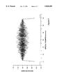
- FIG. 2 is a graph of the s-polarization internal transmittance of a polarizing beamsplitter having an embedded rugate filter with the refractive index profile illustrated in FIG. 1;
- FIG. 3 is a top plan view of two right angle prisms joined with an embedded rugate filter between the hypotenuse faces;
- FIG. 4 is a top plan view of prisms joined in the form of a parallelepiped with an embedded rugate filter
- FIG. 5 is a top plan view of prisms joined in a trapezoidal form with an embedded rugate filter
- FIG. 6 is a graph of the refractive index profile of a rugate filter having an average refractive index that is greater than that of the media in which it is embedded;
- FIG. 7 is a graph of the s-polarization internal transmittance of a polarizing beamsplitter having an embedded rugate filter with the refractive index profile illustrated in FIG. 6;
- FIG. 8 is a graph of the refractive index profile of a rugate filter having three superimposed sinusoidal profiles and an average refractive index that is greater than that of the media in which it is embedded;
- FIG. 9 is a graph of the s-polarization internal transmittance of a polarizing beamsplitter having an embedded rugate filter with the refractive index profile illustrated in FIG. 8.
- the present invention comprises a polarizing beamsplitter that can function as a polarizer, a beamsplitter, or a polarizing beamsplitter.
- the polarizing function converts unpolarized or natural light into polarized light.
- the beamsplitting function separates a beam of incident light into two beams traveling different directions.
- the polarizing beamsplitting function separates a beam of incident light into two beams having different polarizations and directions.
- the multilayer dielectric coating of the prior art MacNeille polarizer is replaced with a thin film having a variation in refractive index (i.e., a gradient index) through its thickness.
- the gradient index film comprises a rugate filter.
- the refractive index n(x) for a single sine wave rugate filter is given by: ##EQU1##
- n a average refractive index
- n pv peak-to-valley refractive index excursion
- ⁇ r center wavelength of the reflection band
- ⁇ sine wave phase at the substrate.
- the wavelength, ⁇ r which spectrally locates the center of the reflection band at a normal angle of incidence, is given by:
- a thin film 34 having a refractive index gradient (such as a rugate filter, for example) is embedded in a supporting optical medium 32, such as a pair of joined prisms.
- Rugate filter 34 is embedded so that an incident light beam in the embedding medium forms an angle ⁇ i with respect to a normal 36 from the interface plane of the rugate filter.
- the rugate filter is highly transmissive for both the p- and s-polarized components of the incident light, except at highly reflective narrow wavelength s-polarization reflection band(s) that are determined by the refractive index variations of the rugate filter.
- rugate filters for the visible/near infrared spectral region have been fabricated of the following materials: SiO 2 /TiO 2 , SiO x , and SiO x Ni y .
- Rugate filters for infrared applications have been fabricated of the following materials: Ge/Si, ZnS/ZnSe, Ge/ZnS and Al 1-x Ga x As (where 0 ⁇ x ⁇ 1).
- the fabrication of polarizing beamsplitters having multiple reflection bands is limited only by the upper and lower refractive indices of the rugate filter materials.
- the optical materials used to fabricate the polarizing beamsplitter should exhibit low absorption within the passband of the beamsplitter.
- an optical quality cement should be selected to minimize the refractive index discontinuity between the rugate filter and embedding material.
- anti-reflection coatings can be deposited on the appropriate external faces of the polarizing beamsplitter to reduce the refractive index discontinuity between the optical material and the surrounding medium from which light enters and exits. This discontinuity in the refractive index can produce a Fresnel reflection that results in a loss in light.
- the average refractive index of the rugate filter is designed to equal the refractive index of the embedding medium.
- the design of this rugate filter, as illustrated in FIG. 1, is convenient when the materials used to fabricate the rugate filter allow refractive index excursions that are both higher and lower than the refractive index of the embedding medium.
- the rugate filter illustrated in FIG. 1 has 100.5 sinusoidally varying cycles with a maximum peak-to-valley refractive index excursion of 0.06 around the refractive index of the fused silica embedding medium (1.46).
- the entire refractive index profile of the rugate filter is also apodized by a half cycle sine-wave enveloping function to enhance the internal transmittance of the resulting optic.
- the optimal angle for incident light is determined by finding the incidence angle ( ⁇ i ) which satisfies the Brewster condition described by the equation: ##EQU3## n i and n t are the refractive indices of the incident medium and the transmitted medium, respectively.
- the incident medium is the embedding medium (e.g., fused silica prism) and the transmitted medium is the rugate filter.
- the Brewster condition indicates that the light within the beamsplitter should travel at an incidence angle of 45° with respect to a normal with the rugate interface.
- a polarizing beamsplitter with a rugate filter at a 45° angle ( ⁇ i ) can take the shape of a cube, as illustrated in the top plan view of FIG. 3.
- This embodiment can be formed of two right angle prisms with the rugate filter between the joined hypotenuse faces.
- This polarizing beamsplitter is highly transmissive for both p- and s-polarized light except at the highly reflective narrow wavelength s-polarization reflection band(s). The p-polarized light is simply transmitted by the optic while the s-polarized light is redirected by reflection.
- the two beams of light exiting the polarizing beamsplitter are orthogonal to one another.
- the foregoing embodiment is designed to produce a highly transmitting polarizing beamsplitter having a single s-polarization reflection band at a wavelength of 0.532 microns, which is the second harmonic of the 1.064 micron Neodymium:YAG laser.
- the s-polarization transmittance of this polarizing beamsplitter is illustrated in FIG. 2.
- the dashed vertical line in FIG. 2 indicates the laser wavelength at 0.532 microns.
- This reflection band has a full-width-half-maximum bandwidth of approximately 3.1 percent.
- FIG. 2 shows that the beamsplitter's internal transmittance of s-polarized light is very high over the remainder of the visible spectrum.
- the internal transmittance from 0.4 to 0.7 microns is greater than 0.99 except for a small part of the sidelobe adjacent to the s-polarization reflection band (on the short wavelength side).
- the internal transmittance for p-polarized light (not illustrated) is also extremely high, with only a single narrow dip (with transmittance greater than 0.999995) centered at 0.532 microns. Therefore, except for the narrow s-polarization reflection band around 0.532 microns, this beamsplitter is highly transmissive to incident light.
- a second embodiment of the invention is useful when the lowest achievable refractive index of the rugate filter is greater than the refractive index of the embedding medium.
- the p-polarization reflection can be suppressed by applying Brewster's condition for a high-low quarterwave stack, such that ##EQU4##
- the angle of propagation ( ⁇ L ) in a rugate filter is related to the angle in the incident medium ( ⁇ i ) by Snell's law:
- the combination of these conditions yields an incidence angle in the incident medium that suppresses the p-polarization reflection.
- the high and low excursions of the index of refraction may be expressed as:
- n H n average +1/2 (n peak-to-valley ),
- n L n average -1/2 (n peak-to-valley ).
- the incidence angle in the embedding medium of a polarizing beamsplitter at the rugate filter interface may be expressed as: ##EQU5##
- An exemplary refractive index profile for a rugate filter of this embodiment of a polarizing beamsplitter is illustrated in FIG. 6.
- This rugate filter (as an example) has 120.5 cycles with a maximum peak-to-valley refractive index excursion of 0.04.
- the entire refractive index profile of this rugate filter is greater than the refractive index of the embedding medium (1.46 for fused silica prisms, for example).
- this rugate filter is apodized by a half cycle sine-wave enveloping function to enhance the internal transmittance of the optic.
- apodization is applied only to the initial and final 45.25 cycles of the rugate filter, so that the middle 30 cycles are not apodized.
- a quintic function (see U.S. Pat. No. 4,583,822) is applied to terminate the ends of the rugate filter at a refractive index of 1.52. The quintic function is used to minimize the refractive index discontinuity between the rugate filter and embedding medium.
- the resulting beamsplitting optic may be shaped as a parallelepiped or trapezoidal polarizing beamsplitter, as illustrated in the top plan views of FIGS. 4 and 5, respectively.
- the incident and exiting beams of light are normal to the external faces of the polarizing beamsplitters.
- the embodiment illustrated in FIG. 6, like the first embodiment illustrated in FIG. 1, is designed to produce a highly transmitting polarizing beamsplitter having a single s-polarization reflection band at 0.532 microns.
- the s-polarization transmittance of this embodiment is illustrated in FIG. 7.
- the dashed vertical line again indicates the 0.532 micron laser wavelength of interest.
- the reflection band for this embodiment has a full-width-half-maximum bandwidth of approximately 1.0 percent centered around the 0.532 micron wavelength.
- the bandwidth of the reflection band has been narrowed (compared with that of the first embodiment illustrated in FIG. 2) by decreasing the peak-to-valley excursion in the sine wave refractive index profile (FIG. 6).
- FIG. 6 As in the first embodiment (see FIG.
- FIG. 7 shows numerous sidelobes having very small internal transmittance variations. However, nearly all of the s-polarization internal transmittance is greater than 0.99.
- the internal transmittance for p-polarized light also has numerous small variations (not illustrated), but all p-polarization transmittance values are greater than 0.999.
- FIG. 8 illustrates a refractive index profile for a rugate filter having an average refractive index of 1.65 (which is higher than the refractive index of the embedding medium (1.46 in this example), as described above in conjunction with the embodiment of FIG. 6).
- the profile of FIG. 8 results from the superposition of three sine waves, with peak-to-valley refractive index excursions of 0.06, 0.045, and 0.045, respectively.
- the maximum and minimum refractive indices possible for this filter are 1.725 and 1.575, respectively (i.e., 1.65 ⁇ 1/2 (0.06+0.045+0.045)).
- Using these values in the incidence angle equation above yields an incidence angle ( ⁇ i ) within the embedding medium of 52.81° from the normal to the rugate filter interface.
- the superposition of the three sine waves may fall short in the thousandth's place of obtaining the maximum of 1.725 and minimum of 1.575, which may affect the incidence angle ( ⁇ i ) in the hundredths place.
- the effect on the resulting s- or p-polarization spectral performance is negligible.
- the refractive index profile illustrated in FIG. 8 also utilizes a sinusoidal apodization envelope and a quintic matching between the average refractive index of the filter and the refractive index of the embedding medium.
- the resulting refractive index profile undergoes refractive index variations in amplitude and rate that can be large and rapid or small and slow.
- the rugate filter illustrated in FIG. 8 is designed to produce three s-polarization reflectance bands located at 0.532, 0.694, and 0.904 microns, respectively, as illustrated in FIG. 9. These three wavelengths, which correspond to the output of a double Neodymium YAG laser, a ruby laser, and a gallium arsenide diode laser, are identified by dashed vertical lines in FIG. 9.
- the diode laser wavelength (0.904 microns) is found in range finders used by sailing crews and radar guns used by law enforcement agencies.
- the three s-polarization reflection bands have full-width-half-maximum bandwidths of 2.8, 3.0, and 4.0 percent, respectively.
- the internal transmittance for s-polarized light outside of the three reflection bands is generally greater than 0.99.
- the internal transmittance for p-polarized light is generally greater than 0.999, with only two small sidelobes (having transmittance greater than 0.997) at about 0.452 microns (not illustrated).
Abstract
Description
Claims (7)
Priority Applications (1)
| Application Number | Priority Date | Filing Date | Title |
|---|---|---|---|
| US08/631,509 US5828489A (en) | 1996-04-12 | 1996-04-12 | Narrow wavelength polarizing beamsplitter |
Applications Claiming Priority (1)
| Application Number | Priority Date | Filing Date | Title |
|---|---|---|---|
| US08/631,509 US5828489A (en) | 1996-04-12 | 1996-04-12 | Narrow wavelength polarizing beamsplitter |
Publications (1)
| Publication Number | Publication Date |
|---|---|
| US5828489A true US5828489A (en) | 1998-10-27 |
Family
ID=24531513
Family Applications (1)
| Application Number | Title | Priority Date | Filing Date |
|---|---|---|---|
| US08/631,509 Expired - Lifetime US5828489A (en) | 1996-04-12 | 1996-04-12 | Narrow wavelength polarizing beamsplitter |
Country Status (1)
| Country | Link |
|---|---|
| US (1) | US5828489A (en) |
Cited By (30)
| Publication number | Priority date | Publication date | Assignee | Title |
|---|---|---|---|---|
| US6052214A (en) * | 1998-01-23 | 2000-04-18 | Chuang; Chih-Li | System and method for producing an enhanced image |
| WO2000058772A1 (en) * | 1999-03-26 | 2000-10-05 | Unaxis Balzers Aktiengesellschaft | Spectral light splitting and recombination device, and method for modulating light in a spectrally selective manner |
| WO2000033729A3 (en) * | 1998-12-10 | 2000-10-26 | Zeiss Carl Jena Gmbh | System and method for the non-contacting measurement of the axis length and/or cornea curvature and/or anterior chamber depth of the eye, preferably for intraocular lens calculation |
| US6288844B1 (en) * | 1999-02-04 | 2001-09-11 | Unaxis Balzers Aktiengesellschaft | Light splitter and optical transmitter configuration with a light splitter |
| WO2002027385A2 (en) * | 2000-09-27 | 2002-04-04 | Innovative Technology Licensing, Llc | Wide-angle rugate polarizing beamsplitter |
| US6693749B2 (en) * | 2001-01-31 | 2004-02-17 | Raytheon Company | Low-observability, wide-field-of-view, situation awareness viewing device |
| US20040218280A1 (en) * | 2001-08-20 | 2004-11-04 | Nevis Elizabeth A | Optical element that is adjustable for optimizing extinction ratios |
| US20050036218A1 (en) * | 2003-08-15 | 2005-02-17 | David Lunt | Neutral white-light filter device |
| US20050280895A1 (en) * | 2004-05-12 | 2005-12-22 | Kaertner Franz X | Multi-layer thin-film broadband beam splitter with matched group delay dispersion |
| US7123416B1 (en) * | 2003-05-06 | 2006-10-17 | Semrock, Inc. | Method of making high performance optical edge and notch filters and resulting products |
| US20070095958A1 (en) * | 2003-08-22 | 2007-05-03 | Yorio Wada | Optical filter and optical instrument |
| US20080055719A1 (en) * | 2006-08-31 | 2008-03-06 | Perkins Raymond T | Inorganic, Dielectric Grid Polarizer |
| US7565084B1 (en) | 2004-09-15 | 2009-07-21 | Wach Michael L | Robustly stabilizing laser systems |
| US7800823B2 (en) | 2004-12-06 | 2010-09-21 | Moxtek, Inc. | Polarization device to polarize and further control light |
| US7813039B2 (en) | 2004-12-06 | 2010-10-12 | Moxtek, Inc. | Multilayer wire-grid polarizer with off-set wire-grid and dielectric grid |
| US7901870B1 (en) | 2004-05-12 | 2011-03-08 | Cirrex Systems Llc | Adjusting optical properties of optical thin films |
| US7917255B1 (en) | 2007-09-18 | 2011-03-29 | Rockwell Colllins, Inc. | System and method for on-board adaptive characterization of aircraft turbulence susceptibility as a function of radar observables |
| US7961393B2 (en) | 2004-12-06 | 2011-06-14 | Moxtek, Inc. | Selectively absorptive wire-grid polarizer |
| US8248696B2 (en) | 2009-06-25 | 2012-08-21 | Moxtek, Inc. | Nano fractal diffuser |
| WO2012164031A1 (en) | 2011-06-01 | 2012-12-06 | Barco N.V. | Apparatus and method for combining laser beams of different polarization |
| US8427769B1 (en) * | 2011-12-14 | 2013-04-23 | Raytheon Company | Multi-stage Lyot filter and method |
| US8611007B2 (en) | 2010-09-21 | 2013-12-17 | Moxtek, Inc. | Fine pitch wire grid polarizer |
| US8755113B2 (en) | 2006-08-31 | 2014-06-17 | Moxtek, Inc. | Durable, inorganic, absorptive, ultra-violet, grid polarizer |
| US8817371B1 (en) * | 2008-08-01 | 2014-08-26 | Simon Andrew Boothroyd | Polarizing beam splitters |
| US8873144B2 (en) | 2011-05-17 | 2014-10-28 | Moxtek, Inc. | Wire grid polarizer with multiple functionality sections |
| US8913321B2 (en) | 2010-09-21 | 2014-12-16 | Moxtek, Inc. | Fine pitch grid polarizer |
| US8913320B2 (en) | 2011-05-17 | 2014-12-16 | Moxtek, Inc. | Wire grid polarizer with bordered sections |
| US8922890B2 (en) | 2012-03-21 | 2014-12-30 | Moxtek, Inc. | Polarizer edge rib modification |
| US9348076B2 (en) | 2013-10-24 | 2016-05-24 | Moxtek, Inc. | Polarizer with variable inter-wire distance |
| WO2021228287A1 (en) | 2020-05-14 | 2021-11-18 | Univerzita Palackého v Olomouci | Polarizing optical separator for stellar intensity interferometry |
Citations (10)
| Publication number | Priority date | Publication date | Assignee | Title |
|---|---|---|---|---|
| US2403731A (en) * | 1943-04-01 | 1946-07-09 | Eastman Kodak Co | Beam splitter |
| US3704934A (en) * | 1971-08-16 | 1972-12-05 | Union Carbide Corp | Laser polarizing beam splitter |
| US4583822A (en) * | 1984-10-31 | 1986-04-22 | Rockwell International Corporation | Quintic refractive index profile antireflection coatings |
| US4826267A (en) * | 1987-11-30 | 1989-05-02 | Rockwell International Corporation | Spectral filter with integral antireflection coating |
| US4952025A (en) * | 1989-05-31 | 1990-08-28 | The United States Of America As Represented By The Secretary Of The Air Force | Rugate filter incorporating parallel and series addition |
| US5004308A (en) * | 1990-05-23 | 1991-04-02 | Rockwell International Corporation | Rugate reflector |
| US5181143A (en) * | 1991-10-03 | 1993-01-19 | Rockwell International Corporation | Multiple line rugate filter with index clipping |
| US5339441A (en) * | 1992-07-02 | 1994-08-16 | Advanced Intervention Systems, Inc. | Polarizing device with optically contacted thin film interface for high power density ultraviolet light |
| US5347644A (en) * | 1992-06-11 | 1994-09-13 | Sedlmayr Steven R | Three-dimensional image display device and systems and methods for implementation thereof |
| US5579159A (en) * | 1992-02-18 | 1996-11-26 | Asahi Kogaku Kogyo Kabushiki Kaisha | Optical multilayer thin film and beam splitter |
-
1996
- 1996-04-12 US US08/631,509 patent/US5828489A/en not_active Expired - Lifetime
Patent Citations (10)
| Publication number | Priority date | Publication date | Assignee | Title |
|---|---|---|---|---|
| US2403731A (en) * | 1943-04-01 | 1946-07-09 | Eastman Kodak Co | Beam splitter |
| US3704934A (en) * | 1971-08-16 | 1972-12-05 | Union Carbide Corp | Laser polarizing beam splitter |
| US4583822A (en) * | 1984-10-31 | 1986-04-22 | Rockwell International Corporation | Quintic refractive index profile antireflection coatings |
| US4826267A (en) * | 1987-11-30 | 1989-05-02 | Rockwell International Corporation | Spectral filter with integral antireflection coating |
| US4952025A (en) * | 1989-05-31 | 1990-08-28 | The United States Of America As Represented By The Secretary Of The Air Force | Rugate filter incorporating parallel and series addition |
| US5004308A (en) * | 1990-05-23 | 1991-04-02 | Rockwell International Corporation | Rugate reflector |
| US5181143A (en) * | 1991-10-03 | 1993-01-19 | Rockwell International Corporation | Multiple line rugate filter with index clipping |
| US5579159A (en) * | 1992-02-18 | 1996-11-26 | Asahi Kogaku Kogyo Kabushiki Kaisha | Optical multilayer thin film and beam splitter |
| US5347644A (en) * | 1992-06-11 | 1994-09-13 | Sedlmayr Steven R | Three-dimensional image display device and systems and methods for implementation thereof |
| US5339441A (en) * | 1992-07-02 | 1994-08-16 | Advanced Intervention Systems, Inc. | Polarizing device with optically contacted thin film interface for high power density ultraviolet light |
Non-Patent Citations (4)
| Title |
|---|
| Banning, "Practical Methods of Making and Using Multilyaer Filters," Journal of the Optical Society of America, vol. 37, No. 10, pp. 792-797 (Oct. 1947). |
| Banning, Practical Methods of Making and Using Multilyaer Filters, Journal of the Optical Society of America, vol. 37, No. 10, pp. 792 797 (Oct. 1947). * |
| Johnson et al., "Introduction to Rugate Filter Technology," SPIE, vol. 2046, pp. 88-108 (1993). |
| Johnson et al., Introduction to Rugate Filter Technology, SPIE, vol. 2046, pp. 88 108 (1993). * |
Cited By (59)
| Publication number | Priority date | Publication date | Assignee | Title |
|---|---|---|---|---|
| US6052214A (en) * | 1998-01-23 | 2000-04-18 | Chuang; Chih-Li | System and method for producing an enhanced image |
| US9504381B2 (en) | 1998-12-10 | 2016-11-29 | Carl Zeiss Meditec Ag | System and method for the non-contacting measurements of the eye |
| WO2000033729A3 (en) * | 1998-12-10 | 2000-10-26 | Zeiss Carl Jena Gmbh | System and method for the non-contacting measurement of the axis length and/or cornea curvature and/or anterior chamber depth of the eye, preferably for intraocular lens calculation |
| US6779891B1 (en) | 1998-12-10 | 2004-08-24 | Carl Zeiss Jena Gmbh | System and method for non-contacting measurement of the eye |
| US8764195B2 (en) | 1998-12-10 | 2014-07-01 | Carl Zeiss Meditec Ag | System and method for the non-contacting measurements of the eye |
| US6288844B1 (en) * | 1999-02-04 | 2001-09-11 | Unaxis Balzers Aktiengesellschaft | Light splitter and optical transmitter configuration with a light splitter |
| WO2000058772A1 (en) * | 1999-03-26 | 2000-10-05 | Unaxis Balzers Aktiengesellschaft | Spectral light splitting and recombination device, and method for modulating light in a spectrally selective manner |
| WO2002027385A2 (en) * | 2000-09-27 | 2002-04-04 | Innovative Technology Licensing, Llc | Wide-angle rugate polarizing beamsplitter |
| WO2002027385A3 (en) * | 2000-09-27 | 2003-12-24 | Innovative Tech Licensing Llc | Wide-angle rugate polarizing beamsplitter |
| US6693749B2 (en) * | 2001-01-31 | 2004-02-17 | Raytheon Company | Low-observability, wide-field-of-view, situation awareness viewing device |
| US7027223B2 (en) * | 2001-08-20 | 2006-04-11 | Agilent Technologies, Inc. | Optical element that is adjustable for optimizing extinction ratios |
| US20040218280A1 (en) * | 2001-08-20 | 2004-11-04 | Nevis Elizabeth A | Optical element that is adjustable for optimizing extinction ratios |
| US7123416B1 (en) * | 2003-05-06 | 2006-10-17 | Semrock, Inc. | Method of making high performance optical edge and notch filters and resulting products |
| US20050036218A1 (en) * | 2003-08-15 | 2005-02-17 | David Lunt | Neutral white-light filter device |
| US7230754B2 (en) * | 2003-08-15 | 2007-06-12 | Meade Instruments Corp. | Neutral white-light filter device |
| US7312925B2 (en) | 2003-08-22 | 2007-12-25 | Olympus Corporation | Optical filter and optical instrument |
| US20070095958A1 (en) * | 2003-08-22 | 2007-05-03 | Yorio Wada | Optical filter and optical instrument |
| US20070109647A1 (en) * | 2003-08-22 | 2007-05-17 | Yorio Wada | Optical filter and optical instrument |
| US20070109646A1 (en) * | 2003-08-22 | 2007-05-17 | Yorio Wada | Optical filter and optical instrument |
| US20070109645A1 (en) * | 2003-08-22 | 2007-05-17 | Yorio Wada | Optical filter and optical instrument |
| US20070103785A1 (en) * | 2003-08-22 | 2007-05-10 | Yorio Wada | Optical filter and optical instrument |
| US20070109648A1 (en) * | 2003-08-22 | 2007-05-17 | Yorio Wada | Optical filter and optical instrument |
| US7265905B2 (en) * | 2003-08-22 | 2007-09-04 | Olympus Corporation | Optical filter and optical instrument |
| US7271959B2 (en) * | 2003-08-22 | 2007-09-18 | Olympus Corporation | Optical filter and optical instrument |
| US7274512B2 (en) * | 2003-08-22 | 2007-09-25 | Olympus Corporation | Optical filter and optical instrument |
| US7277228B2 (en) | 2003-08-22 | 2007-10-02 | Olympus Corporation | Optical filter and optical instrument |
| US7289268B2 (en) * | 2003-08-22 | 2007-10-30 | Olympus Corporation | Optical filter and optical instrument |
| US20070263287A1 (en) * | 2003-08-22 | 2007-11-15 | Yorio Wada | Optical filter and optical instrument |
| US20070103784A1 (en) * | 2003-08-22 | 2007-05-10 | Yorio Wada | Optical filter and optical instrument |
| US7324283B2 (en) | 2003-08-22 | 2008-01-29 | Olympus Corporation | Optical filter and optical instrument |
| US7369314B2 (en) | 2003-08-22 | 2008-05-06 | Olympus Corporation | Optical filter and optical instrument |
| US7901870B1 (en) | 2004-05-12 | 2011-03-08 | Cirrex Systems Llc | Adjusting optical properties of optical thin films |
| US20050280895A1 (en) * | 2004-05-12 | 2005-12-22 | Kaertner Franz X | Multi-layer thin-film broadband beam splitter with matched group delay dispersion |
| US8986922B1 (en) | 2004-05-12 | 2015-03-24 | Cirrex Systems, Llc | Adjusting optical properties of optical thin films |
| US7256940B2 (en) * | 2004-05-12 | 2007-08-14 | Massachusetts Institute Of Technology | Multi-layer thin-film broadband beam splitter with matched group delay dispersion |
| US7965949B1 (en) | 2004-09-15 | 2011-06-21 | Cirrex Systems Llc | Robustly stabilizing laser systems |
| US9065572B1 (en) | 2004-09-15 | 2015-06-23 | Cirrex Systems, Llc | Robustly stabilizing laser systems |
| US7565084B1 (en) | 2004-09-15 | 2009-07-21 | Wach Michael L | Robustly stabilizing laser systems |
| US8521038B1 (en) | 2004-09-15 | 2013-08-27 | Cirrex Systems, Llc | Robustly stabilizing laser systems |
| US7961393B2 (en) | 2004-12-06 | 2011-06-14 | Moxtek, Inc. | Selectively absorptive wire-grid polarizer |
| US8027087B2 (en) | 2004-12-06 | 2011-09-27 | Moxtek, Inc. | Multilayer wire-grid polarizer with off-set wire-grid and dielectric grid |
| US7800823B2 (en) | 2004-12-06 | 2010-09-21 | Moxtek, Inc. | Polarization device to polarize and further control light |
| US7813039B2 (en) | 2004-12-06 | 2010-10-12 | Moxtek, Inc. | Multilayer wire-grid polarizer with off-set wire-grid and dielectric grid |
| US20080055719A1 (en) * | 2006-08-31 | 2008-03-06 | Perkins Raymond T | Inorganic, Dielectric Grid Polarizer |
| US8755113B2 (en) | 2006-08-31 | 2014-06-17 | Moxtek, Inc. | Durable, inorganic, absorptive, ultra-violet, grid polarizer |
| US7917255B1 (en) | 2007-09-18 | 2011-03-29 | Rockwell Colllins, Inc. | System and method for on-board adaptive characterization of aircraft turbulence susceptibility as a function of radar observables |
| US8817371B1 (en) * | 2008-08-01 | 2014-08-26 | Simon Andrew Boothroyd | Polarizing beam splitters |
| US8248696B2 (en) | 2009-06-25 | 2012-08-21 | Moxtek, Inc. | Nano fractal diffuser |
| US8611007B2 (en) | 2010-09-21 | 2013-12-17 | Moxtek, Inc. | Fine pitch wire grid polarizer |
| US8913321B2 (en) | 2010-09-21 | 2014-12-16 | Moxtek, Inc. | Fine pitch grid polarizer |
| US8913320B2 (en) | 2011-05-17 | 2014-12-16 | Moxtek, Inc. | Wire grid polarizer with bordered sections |
| US8873144B2 (en) | 2011-05-17 | 2014-10-28 | Moxtek, Inc. | Wire grid polarizer with multiple functionality sections |
| WO2012164031A1 (en) | 2011-06-01 | 2012-12-06 | Barco N.V. | Apparatus and method for combining laser beams of different polarization |
| US8427769B1 (en) * | 2011-12-14 | 2013-04-23 | Raytheon Company | Multi-stage Lyot filter and method |
| US8922890B2 (en) | 2012-03-21 | 2014-12-30 | Moxtek, Inc. | Polarizer edge rib modification |
| US9348076B2 (en) | 2013-10-24 | 2016-05-24 | Moxtek, Inc. | Polarizer with variable inter-wire distance |
| US9354374B2 (en) | 2013-10-24 | 2016-05-31 | Moxtek, Inc. | Polarizer with wire pair over rib |
| US9632223B2 (en) | 2013-10-24 | 2017-04-25 | Moxtek, Inc. | Wire grid polarizer with side region |
| WO2021228287A1 (en) | 2020-05-14 | 2021-11-18 | Univerzita Palackého v Olomouci | Polarizing optical separator for stellar intensity interferometry |
Similar Documents
| Publication | Publication Date | Title |
|---|---|---|
| US5828489A (en) | Narrow wavelength polarizing beamsplitter | |
| US5912762A (en) | Thin film polarizing device | |
| US4966438A (en) | Dielectric layer polarizer | |
| EP0112188B1 (en) | Light beam-splitter | |
| US4431258A (en) | Optical fiber transmission system and dichroic beam splitter therefor | |
| US6690513B2 (en) | Rhomb interleaver | |
| US4312570A (en) | High reflectivity coated mirror producing 90 degree phase shift | |
| JPH03126910A (en) | Polarization light source device and polarization beam splitter | |
| JPH03156421A (en) | Polarized light source device | |
| TW201137395A (en) | Compact optical integrator | |
| JP4374774B2 (en) | Polarization conversion optical system and polarization conversion element | |
| CN112526656A (en) | Four-direction depolarization beam splitter prism and preparation method thereof | |
| AU7333400A (en) | Beamsplitter device producting parallel output beams | |
| EP1390796B1 (en) | Wide-angle rugate polarizing beamsplitter | |
| US11360320B2 (en) | Hexahedral polarizing beamsplitter | |
| JP2002048911A (en) | Beam splitter and laser system using the same | |
| US5973835A (en) | Multilayer thin-film broad-band polarizing beam-splitter | |
| JPH03276119A (en) | Multiplexing optical system | |
| Baur | A new type of beam-splitting polarizer cube | |
| US10145999B2 (en) | Polarizing beamsplitter that passes s-polarization and reflects p-polarization | |
| JPH03157621A (en) | Polarization light source | |
| JPH0227301A (en) | Adhesive structure for optical parts | |
| JP2005504324A (en) | Parallel beam generating beam splitter device | |
| JPH03122610A (en) | Anamorphic prism | |
| Gilbert et al. | Giant birefringent optics in multilayer polymer filters |
Legal Events
| Date | Code | Title | Description |
|---|---|---|---|
| AS | Assignment |
Owner name: ROCKWELL INTERNAIONAL CORPORATION, CALIFORNIA Free format text: ASSIGNMENT OF ASSIGNORS INTEREST;ASSIGNORS:SOUTHWELL, WILLIAM H.;HALL, RANDOLPH L.;REEL/FRAME:007938/0904 Effective date: 19960412 |
|
| AS | Assignment |
Owner name: AIR FORCE, UNITED STATES OF AMERICA, OHIO Free format text: ASSIGNMENT OF ASSIGNORS INTEREST;ASSIGNOR:JOHNSON, WALTER E.;REEL/FRAME:008695/0071 Effective date: 19960403 |
|
| AS | Assignment |
Owner name: AIR FORCE, UNITED STATES, VIRGINIA Free format text: CONFIRMATORY LICENSE;ASSIGNOR:ROCKWELL INTERNATIONAL CORPORATION;REEL/FRAME:008891/0252 Effective date: 19960529 |
|
| STCF | Information on status: patent grant |
Free format text: PATENTED CASE |
|
| REMI | Maintenance fee reminder mailed | ||
| FPAY | Fee payment |
Year of fee payment: 4 |
|
| SULP | Surcharge for late payment | ||
| FPAY | Fee payment |
Year of fee payment: 8 |
|
| AS | Assignment |
Owner name: ROCKWELL SCIENTIFIC LICENSING, LLC, CALIFORNIA Free format text: CHANGE OF NAME;ASSIGNOR:INNOVATIVE TECHNOLOGY LICENSING, LLC;REEL/FRAME:018260/0250 Effective date: 20030919 Owner name: INNOVATIVE TECHNOLOGY LICENSING, LLC, CALIFORNIA Free format text: CHANGE OF NAME;ASSIGNOR:ROCKWELL TECHNOLOGIES, LLC;REEL/FRAME:018260/0247 Effective date: 20010628 Owner name: ROCKWELL SCIENCE CENTER, LLC, CALIFORNIA Free format text: MERGER;ASSIGNOR:ROCKWELL SCIENCE CENTER, INC.;REEL/FRAME:018247/0966 Effective date: 19970827 Owner name: ROCKWELL TECHNOLOGIES, LLC, CALIFORNIA Free format text: ASSIGNMENT OF ASSIGNORS INTEREST;ASSIGNOR:ROCKWELL SCIENCE CENTER, LLC;REEL/FRAME:018247/0971 Effective date: 20000330 Owner name: ROCKWELL SCIENCE CENTER, INC., CALIFORNIA Free format text: ASSIGNMENT OF ASSIGNORS INTEREST;ASSIGNOR:ROCKWELL INTERNATIONAL CORPORATION;REEL/FRAME:018247/0954 Effective date: 19961115 |
|
| FPAY | Fee payment |
Year of fee payment: 12 |
|
| AS | Assignment |
Owner name: TELEDYNE LICENSING, LLC, CALIFORNIA Free format text: CHANGE OF NAME;ASSIGNOR:ROCKWELL SCIENTIFIC LICENSING, LLC;REEL/FRAME:028499/0861 Effective date: 20060918 Owner name: TELEDYNE SCIENTIFIC & IMAGING, LLC, CALIFORNIA Free format text: MERGER;ASSIGNOR:TELEDYNE LICENSING, LLC;REEL/FRAME:028486/0540 Effective date: 20111221 |