US5831770A - Projection optical system and exposure apparatus provided therewith - Google Patents
Projection optical system and exposure apparatus provided therewith Download PDFInfo
- Publication number
- US5831770A US5831770A US08/826,062 US82606297A US5831770A US 5831770 A US5831770 A US 5831770A US 82606297 A US82606297 A US 82606297A US 5831770 A US5831770 A US 5831770A
- Authority
- US
- United States
- Prior art keywords
- lens
- lens group
- sub
- positive
- disposed
- Prior art date
- Legal status (The legal status is an assumption and is not a legal conclusion. Google has not performed a legal analysis and makes no representation as to the accuracy of the status listed.)
- Expired - Lifetime
Links
- 230000003287 optical effect Effects 0.000 title claims abstract description 230
- 230000005499 meniscus Effects 0.000 claims description 147
- 239000000758 substrate Substances 0.000 claims description 41
- 238000000034 method Methods 0.000 claims description 32
- 238000005286 illumination Methods 0.000 claims description 20
- 239000002131 composite material Substances 0.000 claims description 12
- 239000004973 liquid crystal related substance Substances 0.000 claims description 8
- 239000004065 semiconductor Substances 0.000 claims description 8
- 206010011416 Croup infectious Diseases 0.000 claims 1
- 201000010549 croup Diseases 0.000 claims 1
- 230000004075 alteration Effects 0.000 description 44
- 206010010071 Coma Diseases 0.000 description 20
- 238000010586 diagram Methods 0.000 description 6
- 201000009310 astigmatism Diseases 0.000 description 5
- 210000001747 pupil Anatomy 0.000 description 5
- 230000008859 change Effects 0.000 description 4
- 239000000463 material Substances 0.000 description 4
- 230000004304 visual acuity Effects 0.000 description 4
- VYPSYNLAJGMNEJ-UHFFFAOYSA-N silicon dioxide Inorganic materials O=[Si]=O VYPSYNLAJGMNEJ-UHFFFAOYSA-N 0.000 description 3
- XUIMIQQOPSSXEZ-UHFFFAOYSA-N Silicon Chemical compound [Si] XUIMIQQOPSSXEZ-UHFFFAOYSA-N 0.000 description 2
- WUKWITHWXAAZEY-UHFFFAOYSA-L calcium difluoride Chemical compound [F-].[F-].[Ca+2] WUKWITHWXAAZEY-UHFFFAOYSA-L 0.000 description 2
- 239000011521 glass Substances 0.000 description 2
- 230000007246 mechanism Effects 0.000 description 2
- QSHDDOUJBYECFT-UHFFFAOYSA-N mercury Chemical compound [Hg] QSHDDOUJBYECFT-UHFFFAOYSA-N 0.000 description 2
- 229910052753 mercury Inorganic materials 0.000 description 2
- 238000012986 modification Methods 0.000 description 2
- 230000004048 modification Effects 0.000 description 2
- 229910052710 silicon Inorganic materials 0.000 description 2
- 239000010703 silicon Substances 0.000 description 2
- 241000276498 Pollachius virens Species 0.000 description 1
- 230000015556 catabolic process Effects 0.000 description 1
- 239000011248 coating agent Substances 0.000 description 1
- 238000000576 coating method Methods 0.000 description 1
- 238000006731 degradation reaction Methods 0.000 description 1
- 230000000694 effects Effects 0.000 description 1
- 239000010436 fluorite Substances 0.000 description 1
- 238000003384 imaging method Methods 0.000 description 1
- 229920002120 photoresistant polymer Polymers 0.000 description 1
- 239000010453 quartz Substances 0.000 description 1
- 230000009467 reduction Effects 0.000 description 1
- 238000000926 separation method Methods 0.000 description 1
Images


Classifications
-
- G—PHYSICS
- G03—PHOTOGRAPHY; CINEMATOGRAPHY; ANALOGOUS TECHNIQUES USING WAVES OTHER THAN OPTICAL WAVES; ELECTROGRAPHY; HOLOGRAPHY
- G03F—PHOTOMECHANICAL PRODUCTION OF TEXTURED OR PATTERNED SURFACES, e.g. FOR PRINTING, FOR PROCESSING OF SEMICONDUCTOR DEVICES; MATERIALS THEREFOR; ORIGINALS THEREFOR; APPARATUS SPECIALLY ADAPTED THEREFOR
- G03F7/00—Photomechanical, e.g. photolithographic, production of textured or patterned surfaces, e.g. printing surfaces; Materials therefor, e.g. comprising photoresists; Apparatus specially adapted therefor
- G03F7/70—Microphotolithographic exposure; Apparatus therefor
- G03F7/70216—Mask projection systems
- G03F7/70241—Optical aspects of refractive lens systems, i.e. comprising only refractive elements
-
- G—PHYSICS
- G02—OPTICS
- G02B—OPTICAL ELEMENTS, SYSTEMS OR APPARATUS
- G02B13/00—Optical objectives specially designed for the purposes specified below
- G02B13/14—Optical objectives specially designed for the purposes specified below for use with infrared or ultraviolet radiation
-
- G—PHYSICS
- G02—OPTICS
- G02B—OPTICAL ELEMENTS, SYSTEMS OR APPARATUS
- G02B13/00—Optical objectives specially designed for the purposes specified below
- G02B13/22—Telecentric objectives or lens systems
Definitions
- the present invention relates to a projection optical system for projecting a pattern on a first object onto a substrate or the like as a second object. More particularly, the invention concerns a projection optical system suitably applicable for projection-exposing a pattern for semiconductor or for liquid crystal formed on a reticle (or mask) as a first object onto a substrate (silicon wafer, glass plate, etc.) as a second object.
- a light source for exposure is changing recently from one for emitting light of exposure wavelength of the g-line (436 nm) to one for emitting light of exposure wavelength of the i-line (365 nm), which is mainly used these years. Further, light sources for emitting light of further shorter wavelengths, for example excimer lasers (248 nm, 193 nm), are being used as a light source for exposure.
- the projection optical systems are demanded to decrease image distortion as well as to improve the resolving power.
- the image distortion is caused by distortion due to the projection optical system, warpage of the wafer to be printed on the image side of projection optical system, warpage of the reticle with circuit patterns etc. written thereon on the object side of projection optical system, etc.
- a projection optical system according to the present invention is a so-called bitelecentric projection optical system, which is telecentric both on the object side and on the image side.
- An object of the invention is to provide a projection optical system which can greatly improve aberrations, particularly distortion (including higher-order distortions) while securing a relatively wide exposure area and a large numerical aperture (NA).
- the projection optical system according to the present invention can be applied to either of exposure apparatus utilizing a scanning exposure method and exposure apparatus utilizing a one-shot exposure method.
- An exposure apparatus to which the projection optical system of the present invention is applied comprises, at least, a first stage (wafer stage WS) capable of holding a photosensitive substrate on a main surface thereof, an illumination optical system IS for transferring a predetermined pattern on said mask onto a substrate, and a second stage (reticle stage RS) for holding the mask, and the projection optical system PL of the present invention is arranged between the mask (first object) and the substrate (second object) to project an image of the mask onto the substrate (see FIG. 2).
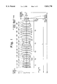
- the projection optical system comprises, for example as shown in FIG. 1, a first lens group G 1 having a positive refractive power, a second lens group G 2 having a negative refractive power, a third lens group G 3 having a positive refractive power, a fourth lens group G 4 having a negative refractive power, a fifth lens group G 5 having a positive refractive power, and a sixth lens group G 6 having a positive refractive power, arranged in the stated order from the mask (first object) to the substrate (second object).
- the second lens group G 2 does not include any positive lens
- the second lens group G 2 comprises a front lens L 2F with a negative refractive power, arranged nearest to the mask and having a concave surface directed to the substrate side, a rear lens L 2R with a negative refractive power, arranged nearest to the substrate and having a concave surface directed to the mask side, and an intermediate lens group G 2m having at least two negative lenses, disposed between the front lens L 2F and the rear lens L 2R .
- the above fifth lens group G 5 comprises at least seven positive lenses.
- the first lens group G 1 having the positive refractive power contributes mainly to correction for distortion while maintaining telecentricity. Specifically, the first lens group G 1 generates a positive distortion, which corrects in a good balance a negative distortion caused by the plurality of lens groups located on the second object side of the first lens group G 1 .
- the second lens group G 2 having the negative refractive power and the fourth lens group G 4 having the negative refractive power contribute mainly to correction for Petzval sum in order to flatten the image plane.
- the second lens group G 2 having the negative refractive power and the third lens group G 3 having the positive refractive power compose an inverted telescopic system.
- This inverted telescopic system contributes to securing the back focus (which is a distance from an optical surface, for example a lens surface, nearest to the second object in the projection optical system to the second object) of the projection optical system.
- the fifth lens group G 5 having the positive refractive power and the sixth lens group G 6 similarly having the positive refractive power contribute to suppressing generation of distortion.
- these lens groups G 5 , G 6 contribute to suppressing occurrence of spherical aberration as much as possible in order to get ready well for higher NA on the second object side.
- the front lens L 2F arranged nearest to the first object in the second lens group G 2 having the concave surface directed to the second object side, and having the negative refractive power
- the rear lens L 2R arranged nearest to the second object in the second lens group G 2 having the concave surface directed to the first object, and having the negative refractive power both contribute to correction for curvature of field and coma.
- the intermediate lens group G 2m disposed between the front lens L 2F and the rear lens L 2R and having the negative refractive power greatly contributes to correction for curvature of field.
- the intermediate lens group G 2m is composed of only negative lenses.
- the setup of the entire second lens group G 2 composed of only negative lenses shortens the total length of the projection optical system while well suppressing occurrence of higher-order distortions, which are likely to occur in the intermediate lens group.
- the intermediate lens group G 2m includes at least two negative lenses. This setup contributes to fully suppressing occurrence of coma.
- the fifth lens group G 5 includes at least seven positive lenses.
- This setup allocates the refractive power to be born by the fifth lens group itself to the respective positive lenses in a good balance.
- negative spherical aberration which is likely to occur in the fifth lens group G 5 with an increase in numerical aperture (NA), can be well suppressed. Accordingly, this setup (where the fifth lens group G 5 includes at least seven positive lenses) assures high resolving power of projection optical system.
- the projection optical system according to the present invention satisfies the following conditions, when the focal length of the first lens group G 1 is f 1 , the focal length of the second lens group G 2 is f 2 , the focal length of the third lens group G 3 is f 3 , the focal length of the fourth lens group G 4 is f 4 , the focal length of the fifth lens group G 5 is f 5 , the focal length of the sixth lens group G 6 is f 6 , the composite focal length of the intermediate lens group G 2m in the second lens group G 2 is f 2m , and a distance between the object plane P 1 on the mask and the image plane P 2 on the substrate is L.
- Condition (1) defines an optimum ratio of the focal length f 1 of the first lens group G 1 of the positive refractive power and the focal length f 3 of the third lens group G 3 of the positive refractive power, which is an optimal refractive power balance (power balance) between the first lens group G 1 and the third lens group G 3 .
- This condition (1) is a condition for mainly achieving well-balanced correction for distortion. Accordingly, if the ratio were set below the lower limit of condition (1), great negative distortion would appear, because the refractive power of the third lens group G 3 becomes relatively weaker than the refractive power of the first lens group G 1 . If the ratio were set above the upper limit of condition (1), great negative distortion would appear, because the refractive power of the first lens group becomes relatively weaker than the refractive power of the third lens group.
- Condition (2) defines an optimum ratio of the focal length f 2 of the second lens group G 2 of the negative refractive power and the focal length f 4 of the fourth lens group G 4 of the negative refractive power, which is an optimal refractive power balance (power balance) between the second lens group G 2 of the negative refractive power composed of only the plurality of negative lenses and the fourth lens group G 4 of the negative refractive power.
- This condition (2) is a condition for mainly achieving good correction for curvature of field while securing a wide exposure field as keeping Petzval sum small. Accordingly, if the ratio were set below the lower limit of this condition (2), great positive Petzval sum would occur because the refractive power of the fourth lens group G 4 becomes relatively weaker than that of the second lens group G 2 .
- Condition (3) defines an optimum ratio of the focal length f 5 of the fifth lens group G 5 of the positive refractive power to the distance (object-image distance) L from the object plane P1 of the first object (reticle or the like) to the image plane P2 of the second object (wafer or the like).
- This condition (3) is a condition for achieving well-balanced correction for spherical aberration, distortion, and Petzval sum while maintaining a large numerical aperture. Accordingly, if the ratio were set below the lower limit of this condition (3), the refractive power of the fifth lens group G 5 would become too strong, so that the fifth lens group G 5 gives rise to great negative spherical aberration as well as negative distortion.
- the lower limit of above condition (3) In order to fully suppress negative spherical aberration, which is likely to occur in the fifth lens group G 5 , it is preferred to set the lower limit of above condition (3) to 0.081 so as to be 0.081 ⁇ f 5 /L. Conversely, if the ratio were set above the upper limit of this condition (3), the refractive power of the fifth lens group G 5 would become too weak, and with it the refractive power of the fourth lens group G 4 with the negative refractive power would naturally become weak. As a result, it would become impossible to correct Petzval sum well.
- Condition (4) defines an optimum ratio of the focal length f 6 of the sixth lens group G 6 of the positive refractive power to the distance (object-image distance) L from the object plane P1 of the first object (reticle or the like) to the image plane P2 of the second object (wafer or the like).
- This condition (4) is a condition for suppressing occurrence of higher-order spherical aberrations and negative distortion while maintaining a large numerical aperture. Accordingly, if the ratio were set below the lower limit of this condition (4), the sixth lens group itself would give rise to great negative distortion. On the other hand, if the ratio were set above the upper limit of this condition (4), higher-order spherical aberrations would occur.
- Condition (5) defines an optimum ratio of the composite focal length f 2m of the intermediate lens group G 2m having the negative refractive power in the second lens group G 2 and the focal length f 2 of the second lens group G 2 .
- This condition (5) is a condition for keeping Petzval sum small while suppressing occurrence of distortion. Accordingly, if the ratio were set below the lower limit of this condition (5), the negative composite refractive power of the intermediate lens group G 2m in the second lens group G 2 would become too strong, so that great negative distortion would occur. In order to fully suppress occurrence of distortion and coma, it is preferred to set the lower limit of above condition (5) to 1.86 so as to be 1.86 ⁇ f 2m /f 2 .
- the ratio were set above the upper limit of this condition (5), the negative refractive power of the intermediate lens group G 2m in the second lens group G 2 would become too weak, so that great positive Petzval sum would result.
- the refractive power of the third lens group G 3 also would become weak, which makes compactification of projection optical system difficult.
- the projection optical system is preferably arranged to satisfy the following condition (6) when an axial distance from the first object to the first object side focal point of the overall projection optical system is I and the distance from the first object to the second object is L.
- Condition (6) defines an optimum ratio of the axial distance I from the first object to the first object side focal point of the overall projection optical system to the distance (object-image distance) L from the object plane P1 of the first object (reticle or the like) to the image plane P2 of the second object (wafer or the like).
- the first object side focal point of the overall projection optical system means an intersecting point of light emerging from the projection optical system with the optical axis thereof when parallel light in the paraxial region relative to the optical axis of the projection optical system is made to enter the projection optical system from the second object side thereof and the light in the paraxial region emerges from the projection optical system (see FIG. 1).
- the fifth lens group G 5 having the positive refractive power is provided, as shown in FIG. 1, with a negative meniscus lens L 55 , and a first positive lens L 54 disposed adjacent to a concave surface of the negative meniscus lens L 55 and having a convex surface opposed to the concave surface of the negative meniscus lens L 55 .
- the fifth lens group G 5 is arranged more preferably to satisfy the following condition (7) when r 5n is a radius of curvature of the concave surface of the negative meniscus lens L 55 in the fifth lens group G 5 and r 5p is a radius of curvature of the convex surface of the first positive lens L 54 , opposed to the concave surface of the negative meniscus lens L 55 .
- the fifth lens group G 5 have at least one positive lens on the convex surface side of the negative meniscus lens L 55 disposed adjacent to the above first positive lens L 54 and at least one positive lens on the opposite side to the negative meniscus lens L 55 , with respect to the above first positive lens L 54 disposed adjacent to the negative meniscus lens L 55 .
- These positive lenses correspond to, for example in the case of the lens setup of FIG. 1, the lens L 53 (second positive lens) and lens L 56 (third positive lens). This setup can suppress occurrence of higher-order spherical aberrations, which are likely to occur with an increase in NA.
- the sixth lens group G 6 is arranged more preferably to satisfy the following condition (8) when r 6F is a radius of curvature of a lens surface nearest to the first object in the sixth lens group G 6 and d 6 is an axial distance from the lens surface nearest to the first object in the sixth lens group G 6 to the second object (see FIG. 1).
- the ratio were set above the upper limit of this condition (8), the positive refractive power of the lens surface nearest to the first object in the sixth lens group G 6 would become too strong, thereby causing great negative distortion and coma. If the ratio were set below the lower limit of this condition (8), the positive refractive power of the lens surface nearest to the first object in the sixth lens group G 6 would become too weak, thereby causing great coma. In order to suppress occurrence of coma more, it is desired to set the lower limit of condition (8) to 0.84 so as to be 0.84 ⁇ d 6 /r 6F .
- the fifth lens group G 5 is desirably arranged to have a negative lens L 59 with a concave surface directed to the second object side, located nearest to the second object. Since this setup causes the negative lens L 59 located nearest to the second object in the fifth lens group G 5 to generate positive distortion and negative Petzval sum, they can cancel negative distortion and positive Petzval sum caused by the positive lenses in the fifth lens group G 5 .
- the fifth lens group G 5 is arranged more desirably to satisfy the following condition (9) when r 5F is a radius of curvature of a first object side lens surface in the negative lens L 59 located nearest to the second object in the fifth lens group G 5 and r 5R is a radius of curvature of the second object side lens surface in the negative lens L 59 located nearest to the second object in the fifth lens group G 5 .
- the fifth lens group G 5 is provided with a first positive meniscus lens L 51 disposed nearest to the first object and having a convex surface directed to the second object side, and a second positive meniscus lens L 52 disposed on the second object side of the first positive meniscus lens L 51 and having a convex surface directed to the second object side.
- the fifth lens group G 5 is more preferably arranged to satisfy the following condition when r 51F is a radius of curvature of a first object side lens surface in the first positive meniscus lens L 51 in the fifth lens group G 5 , r 51R is a radius of curvature of the second object side lens surface in the first positive meniscus lens L 51 in the fifth lens group G 5 , r 52F is a radius of curvature of a first object side lens surface in the second positive meniscus lens L 52 in the fifth lens group G 5 , and r 52R is a radius of curvature of the second object side lens surface in the second positive meniscus lens L 52 in the fifth lens group G 5 .
- this condition (10) If the ratio of shape factors of this condition (10) were set above the upper limit thereof or below the lower limit thereof, it would become difficult to correct for spherical aberration and coma occurring in the fifth lens group G 5 . As a result, it would become impossible to realize excellent imaging performance. In order to achieve better-balanced correction for spherical aberration, it is preferred to set the lower limit of condition (10) to 3.3 so as to be 3.3 ⁇ Q 25 /Q 51 .
- the fifth lens group G 5 is arranged much more preferably to satisfy the following condition when r 51F is the radius of curvature of the first object side lens surface in the first positive meniscus lens L 51 in the fifth lens group G 5 and r 51R is the radius of curvature of the second object side lens surface in the first positive meniscus lens L 51 in the fifth lens group G 5 .
- the shape factor Q 51 in this condition (10) were set above the upper limit thereof or below the lower limit thereof, it would unpreferably become difficult to fully correct for spherical aberration occurring in the fifth lens group G 5 .
- the front lens L 2F and rear lens L 2R in the second lens group G 2 preferably satisfy the following condition when f 2F is the focal length of the front lens L 2F and f 2R is the focal length of the rear lens L 2R .
- Condition (12) defines an optimum ratio of the focal length f 2R of the rear lens L 2R in the second lens group G 2 and the focal length f 2F of the front lens L 2F in the second lens group G 2 . If the ratio of this condition (12) were set above the upper limit thereof or below the lower limit thereof, the balance of refractive power of the first lens group G 1 or the third lens group G 3 would be destroyed. As a result, it would become difficult to achieve good correction for distortion or simultaneous good correction for Petzval sum and astigmatism.
- the first lens group G 1 is preferably arranged to have at least two positive lenses.
- the third lens group G 3 is made to have a function to suppress degradation of spherical aberration and Petzval sum
- the third lens group G 3 is preferably arranged to have at least three positive lenses.
- the fourth lens group G 4 is made to have a function to suppress occurrence of coma while correcting for Petzval sum
- the fourth lens group G 4 is preferably arranged to have at least three negative lenses.
- the fifth lens group G 5 is made to have a function to suppress occurrence of spherical aberration, the fifth lens group G 5 is preferably arranged to have at least seven positive lenses. In addition, in order that the fifth lens group G 5 is made to have a function to correct for negative distortion and Petzval sum, the fifth lens group G 5 is preferably arranged to have at least one negative lens. In order that the sixth lens group G 6 is made to condense the light on the second surface while not giving rise to great spherical aberration, the sixth lens group G 6 is preferably arranged to have at least one positive lens.
- the sixth lens group G 6 is preferably arranged to be composed of three or less lenses having at least one lens surface to satisfy the following condition (13). In other words, it is preferred that the lenses constituting the sixth lens group G 6 have at least one lens surface to satisfy the following condition.
- ⁇ a refractive power of the lens surface
- L the object-image distance from the first object to the second object.
- the refractive power of the lens surface stated herein is defined by the following equation when r is a radius of curvature of the lens surface, n 1 is a refractive index of a first-object-side medium of the lens surface, and n 2 is a refractive index of a second-object-side medium of the lens surface.
- FIG. 1 is a drawing to illustrate common parts to lens layouts of the projection optical system according to the present invention
- FIG. 2 is a drawing to show the schematic setup of a scanning exposure apparatus to which the projection optical system according to the present invention can be applied;
- FIG. 3 is a drawing to show the sectional structure of a photosensitive substrate
- FIG. 4 is a drawing to show a lens layout of the first embodiment of the projection optical system according to the present invention.
- FIG. 5 is a drawing to show a lens layout of the second embodiment of the projection optical system according to the present invention.
- FIG. 6 is a drawing to show a lens layout of the third embodiment of the projection optical system according to the present invention.
- FIGS. 7 to 10 are drawings to show various aberrations in the first embodiment shown in FIG. 3;
- FIGS. 11 to 14 are drawings to show various aberrations in the second embodiment shown in FIG. 4;
- FIGS. 15 to 18 are drawings to show various aberrations in the third embodiment shown in FIG. 5;
- FIG. 19 is a drawing to show the schematic setup of an exposure apparatus of the one-shot exposure method to which the projection optical system according to the present invention can be applied.
- FIG. 1 will be made reference to when necessary.
- FIG. 2 is a drawing to show the schematic setup of a scanning exposure apparatus to which the projection optical system according to the present invention can be applied.
- FIG. 2 will be explained briefly.
- the reticle R first object as a photomask in which predetermined circuit patterns are formed is disposed on the object plane P1 of the projection optical system PL
- the wafer W second object as a photosensitive substrate is disposed on the image plane P2 of the projection optical system PL.
- the reticle R is held on a reticle stage RS arranged to move in the X-direction upon exposure
- the wafer W is held on a wafer stage WS arranged to move in the X-direction opposite to movement of the reticle stage RS.
- a slit (rectangular) illumination area IF 1 extending in the Y-direction is formed on the reticle R, and an illumination optical system IS for uniformly illuminating the illumination area IF 1 is disposed above the reticle R. Exposure light is emitted from a light source LS provided in the illumination system.
- the light supplied from the light source LS in the illumination optical system IS illuminates the reticle R in a slit pattern.
- An image of the light source LS in the illumination optical system IS is formed at the position of the pupil (the position of aperture stop AS) of the projection optical system PL, thus realizing so-called Kohler illumination.
- an image of the pattern of reticle R Kohler-illuminated is projected (or transferred) onto the wafer W through the projection optical system PL.
- the photosensitive substrate placed on the above wafer stage WS is one obtained by coating the entire surface of exposed object 100 such as a silicon wafer, a glass plate, or the like with a photosensitive material 200 such as a photoresist, as shown in FIG. 3.
- an area EF 1 of the pattern image of reticle R exposed on the wafer W is a slit pattern (rectangular shape) extending in the Y-direction, as shown in FIG. 2.
- the projection magnification factor of the projection optical system PL is 1/M
- the reticle stage RS and wafer stage WS are moved in mutually opposite directions along the X-direction in the velocity ratio of M:1, whereby the pattern image of the entire surface of reticle R is transferred onto the wafer W.
- the above U.S. patent application Ser. No. 08/255,927 describes the illumination optical system (using a laser light source) applicable to the scanning exposure apparatus.
- the above U.S. patent application Ser. No. 08/260,398 describes the illumination optical system (using a lamp light source) applicable to the scanning exposure apparatus.
- the U.S. patent application Ser. No. 08/299,305 discloses an alignment mechanism applicable to the scanning exposure apparatus.
- the U.S. Pat. No. 4,497,015 describes the illumination optical system (using a lamp light source) applicable to popular exposure apparatus.
- the U.S. Pat. No. 4,666,273 discloses an example of the step-and-repeat type exposure apparatus.
- 5,194,893 discloses the scanning exposure apparatus, particularly, the illumination optical system, illumination area, mask-side and reticle-side interference systems, automatic focusing mechanism, and alignment optical system.
- the U.S. Pat. No. 5,253,110 describes the illumination optical system (using a laser light source) applicable to the step-and-repeat type exposure apparatus.
- the illumination optical system disclosed in this reference can also be applied to the scanning exposure apparatus.
- the U.S. Pat. No. 5,333,035 discloses a modified illumination optical system applicable to popular exposure apparatus.
- the U.S. Pat. No. 5,379,091 discloses the illumination optical system (using a laser light source) applicable to the scanning exposure apparatus.
- U.S. Pat. No. 5,245,384 also shows the illumination optical system using a mercury lamp, applicable to ordinary exposure apparatus (steppers).
- FIG. 4 to FIG. 6 show lens layouts of the first to third embodiments of the projection optical system according to the present invention.
- the projection optical system in each lens layout is composed of, in order from the side of reticle R as a first object, the first lens group G 1 having a positive refractive power, the second lens group G 2 having a negative refractive power, the third lens group G 3 having a positive refractive power, the fourth lens group G 4 having a negative refractive power, the fifth lens group G 5 having a positive refractive power, and the sixth lens group G 6 having the positive refractive power.
- These examples of the projection optical system are approximately telecentric on the object side (on the reticle R side) and on the image side (on the wafer W side), and have demagnification factors.
- the object-image distance (the distance from the object plane P1 to the image plane P2 or the distance from the reticle R to the wafer W) L is 1000
- the image-side numerical aperture NA is 0.6
- the projection magnification B is 1/4
- the diameter of the exposure area on the wafer W, of the projection optical system PL or the diagonal length of the slit exposure area on the wafer W is 26.4.
- the first lens group G 1 has, in order from the object side, a negative lens (negative meniscus lens) L 11 with a concave surface directed to the image side, two positive biconvex lenses L 12 and L 13 , and a positive lens (biconvex lens) L 14 with a convex surface directed to the object side.
- the second lens group G 2 is composed of a negative meniscus lens (front lens) L 2F disposed nearest to the object and having a concave surface directed to the image side, a negative meniscus lens (rear lens) L 2R disposed nearest to the image side and having a concave surface directed to the object side, and an intermediate lens group G 2m disposed between the negative meniscus lens L 2F and the negative meniscus lens L 2R .
- the intermediate lens group G 2m is composed of negative lenses only.
- the intermediate lens group G 2m is composed of, in order from the object side, a negative lens (negative meniscus lens) L m1 with a concave surface directed to the image side, and a negative biconcave lens L m2 .
- the third lens group G 3 is composed of, in order from the object side, a positive lens (positive meniscus lens) L 31 with a convex surface directed to the image side, a positive lens (biconvex lens) L 32 with a convex surface directed to the image side, two positive biconvex lenses L 33 and L 34 , and a positive lens (positive meniscus lens) L 35 with a convex surface directed to the object side.
- the fourth lens group G 4 is composed of, in order from the object side, two negative lenses (two negative meniscus lenses) L 41 and L 42 with their concave surfaces directed to the image side, a negative biconcave lens L 43 , and a negative lens (biconcave lens) L 44 with a concave surface directed to the object side.
- the fifth lens group G 5 is composed of seven positive lenses and two negative lenses. Specifically, the fifth lens group G 5 is composed of, in order from the object side, two positive meniscus lenses L 51 and L 52 with their convex surfaces directed to the image side, two positive biconvex lenses L 53 and L 54 , a negative lens (negative meniscus lens) L 55 with a concave surface directed to the object side, a positive biconvex lens L 56 , two positive lenses (two positive meniscus lenses) L 57 and L 58 with their convex surfaces directed to the object side, and a negative lens (negative meniscus lens) L 59 with a concave surface directed to the image side.
- the sixth lens group G 6 is composed of only a positive lens (positive meniscus lens) L 61 with a convex surface directed to the object side.
- the image-side lens surface of the negative lens (negative meniscus lens) L 11 with the concave surface directed to the image side and the object-side lens surface of the positive biconvex lens L 12 have like curvatures and are located relatively close to each other. These two lens surfaces correct higher-order distortions.
- the front lens L 2F in the second lens group G 2 is formed in a meniscus shape with the concave surface directed to the image side, occurrence of coma is relieved.
- the rear lens L 2R in the second lens group G 2 is formed in a meniscus shape with the concave surface directed to the object side, it can suppress occurrence of coma in combination with the front lens L 2F .
- the intermediate lens group G 2m in the second lens group G 2 is composed of the negative lenses only, occurrence of higher-order distortions is suppressed.
- the fourth lens group G 4 is arranged, as described above, so that the negative lens L 41 with the concave surface directed to the image side is disposed on the object side of the negative biconcave lens L 43 and so that the negative lens L 44 with the concave surface directed to the object side is disposed on the image side of the negative biconcave lens L 43 . Because of this arrangement the fourth lens group G 4 corrects Petzval sum as suppressing occurrence of coma.
- the fifth lens group G 5 includes the seven positive lenses (L 51 , L 52 , L 53 , L 54 , L 56 , L 57 , L 58 ) as described above. Because of this arrangement the fifth lens group G 5 suppresses negative spherical aberration caused by the fifth lens group G 5 itself with an increase in NA. Further, in the fifth lens group G 5 , the fourth positive lens L 54 from the object side has the convex surface opposed to the negative lens (negative meniscus lens) L 55 with the concave surface directed to the object side and also has the convex lens surface on the opposite side (object side) to the negative lens (negative meniscus lens) L 55 with the concave surface directed to the object side.
- the fifth lens group G 5 suppresses occurrence of higher-order spherical aberrations, caused with an increase in NA.
- the first embodiment showed an example in which in order to suppress occurrence of higher-order spherical aberrations caused with an increase in NA, the fifth lens group G 5 was arranged to include the positive biconvex lens L 54 and the negative lens (negative meniscus lens) L 55 with the concave surface directed to the object side, arranged in the stated order from the object side.
- the above same effect can be obtained by arranging them in the reversed order and inverting the concave surface of the negative lens L 55 to the image side, specifically by arranging the negative lens (negative meniscus lens) L 55 with the concave surface directed to the image side and the positive biconvex lens L 54 in the stated order from the object side.
- the aperture stop AS is disposed between the two positive meniscus lenses (L 51 , L 52 ) located on the object side in the fifth lens group G 5 .
- the second embodiment shown in FIG. 5 is different in lens layouts of the second lens group G 2 , the fourth lens group G 4 , and the sixth lens group G 6 from the first embodiment shown in FIG. 4.
- the intermediate lens group G 2m in the second lens group G 2 includes one more negative lens than that in the first embodiment does, and thus, is composed of three negative lenses.
- the intermediate lens group G 2m is composed of, in order from the object side, a negative lens (negative meniscus lens) L m1 with a concave surface directed to the image side, a negative lens (plano-concave lens) L m2 similarly with a concave surface directed to the image side, and a negative biconcave lens L m3 .
- This arrangement of the intermediate lens group G 2m composed of the three negative lenses effectively suppresses coma, which is likely to occur in the intermediate lens group G 2m .
- the negative lens L 44 disposed at the fourth position from the object side and having the concave surface directed to the object side, was a biconcave lens.
- this negative lens L 44 is a plano-concave lens.
- the sixth lens group G 6 of the second embodiment includes one more positive lens than that in the first embodiment does, and thus, is composed of two positive lenses.
- the sixth lens group G 6 is composed of, in order from the object side, two positive lenses (positive meniscus lenses) L 61 and L 62 having their convex surfaces directed to the object side.
- the third embodiment shown in FIG. 6 is different in lens layouts of the first lens group G 1 and the second lens group G 2 from the first embodiment shown in FIG. 4.
- the first lens group G 1 of the third embodiment includes positive lenses one less than those in the first embodiment, and thus, is composed of a negative lens and two positive lenses.
- the first lens group G 1 has, in order from the object side, a negative lens (negative meniscus lens) L 11 with a concave surface directed to the image side, a positive biconvex lens L 12 , and a positive lens (biconvex lens) L 13 with a convex surface directed to the object side.
- the intermediate lens group G 2m in the second lens group G 2 of the third embodiment includes one more positive lens than that in the first embodiment does, and thus, is composed of three negative lenses as in the second embodiment.
- the intermediate lens group G 2m is composed of, in order from the object side, two negative lenses (two negative meniscus lenses) L m1 and L m2 with their concave surfaces directed to the image side, and a negative biconcave lens L m3 .
- This arrangement of the intermediate lens group G 2m composed of the three negative lenses effectively suppresses coma, which is likely to occur in the intermediate lens group G 2m .
- Tables 1-1, 1-2, 2-1, 2-2, 3-1, 3-2 below show specifications and condition correspondence values of the first to third embodiments according to the present invention.
- left-end numerals represent orders from the object side (reticle side), r radii of curvature of lens surfaces, d lens surface separations, n refractive indices of synthetic quartz SiO 2 at the exposure wavelength ⁇ of 248.4 nm, d0 a distance from the object plane (reticle plane) to the most object side (reticle side) lens surface (first lens surface) in the first lens group G 1 (FIG.
- the object-side lens surface of the positive lens L 61 has the value of 1/
- 0.0985, thereby satisfying condition (13).
- the object-side lens surface of the positive lens L 61 has the value of 1/
- 0.122, and the object-side lens surface of the positive lens L 62 has the value of 1/
- 0.383.
- the both lens surfaces satisfy condition (13).
- the object-side lens surface of the positive lens L 61 has the value of 1/
- 0.0966, thus satisfying condition (13). Therefore, the sixth lens group G 6 of each embodiment is composed of three or more lenses having at least one lens surface satisfying condition (13).
- each embodiment achieves telecentricity on the object side (reticle side) and on the image side (wafer side) while securing a relatively wide exposure area and a large numerical aperture.
- FIGS. 7 to 11 are drawings to show various aberrations of the first embodiment of the projection optical system according to the present invention, having the lens layout shown in FIG. 4.
- FIG. 7 is a drawing to show spherical aberration of the first embodiment
- FIG. 8 astigmatism of the first embodiment
- FIG. 9 distortion of the first embodiment
- FIG. 10 coma of the first embodiment.
- NA represents the numerical aperture of the projection optical system
- Y the image height.
- the dotted line indicates the meridional image surface and the solid line the sagittal image surface.
- FIGS. 11 to 14 are drawings to show various aberrations of the second embodiment of the projection optical system according to the present invention, having the lens layout shown in FIG. 5.
- FIG. 11 is a diagram to show spherical aberration of the second embodiment, FIG. 12 astigmatism of the second embodiment, FIG. 13 distortion of the second embodiment, and FIG. 14 coma of the second embodiment.
- FIGS. 15 to 18 are drawings to show various aberrations of the third embodiment of the projection optical system according to the present invention, having the lens layout shown in FIG. 6.
- FIG. 15 is a diagram to show spherical aberration of the third embodiment, FIG. 16 astigmatism of the third embodiment, FIG. 17 distortion of the third embodiment, and FIG. 18 coma of the third embodiment.
- NA represents the numerical aperture of the projection optical system and Y the image height.
- the dotted line indicates the meridional image surface and the solid line the sagittal image surface.
- each embodiment is corrected for various aberrations in a good balance.
- the projection optical system is realized with a large numerical aperture reaching 0.6 and high resolving power while distortion is corrected very well over the entire image to an almost zero state.
- light sources applicable to the each embodiment include extreme ultraviolet light sources such as the ArF excimer laser supplying the light of 193 nm, a mercury arc lamp supplying the light of the g-line (436 nm) and the i-line (365 nm), and light sources supplying light in the ultraviolet region other than those.
- the lenses constituting the projection optical system are not cemented and all are made of a single optical material, that is, silica (SiO 2 ).
- silica SiO 2
- each embodiment as described above is constructed of a single optical material, cost reduction is achieved.
- the exposure light source has a wide band, it is effective to correction for chromatic aberration to construct the projection optical system by preparing plural types of lenses and combining these lenses.
- the examples of the projection optical system of the first to third embodiments were described as applications to the scanning exposure apparatus, as shown in FIG. 2.
- the exposure apparatus to which the projection optical system of the present invention can be applied include exposure apparatus of the one-shot exposure method for printing the patterns of reticle R on the wafer W by one shot, for example, as shown in FIG. 19.
- the projection optical system according to the present invention is the bitelecentric optical system and realizes the high-resolving-power optical system as corrected for various aberrations in a good balance and having the large numerical aperture while securing a relatively wide exposure area.
- the projection optical system of the present invention is corrected very well for distortion (including higher-order distortions). Accordingly, because the projection optical system of the present invention achieves not only bitelecentricity, but also very good correction for distortion, a decrease in image distortion is extreme.
Abstract
This invention is directed to a bitelecentric projection optical system very well corrected for various distortions, particularly for distortion (including higher-order distortions) as securing a relatively wide exposure area and a large numerical aperture. The projection optical system according to this invention comprises in order from the object side toward the image side a first lens group having a positive refractive power, a second lens group having a negative refractive power and not including a positive lens, a third lens group having a positive refractive power, a fourth lens group having a negative refractive power, a fifth lens group having a positive refractive power, and a sixth lens group having a positive refractive power. Particularly, the second lens group comprises a front lens disposed nearest to the object, a rear lens disposed nearest to the image, and an intermediate lens group disposed between the front lens and the rear lens and having at least two negative lenses, and the fifth lens group has at least seven positive lenses.
Description
This is a continuation of application Ser. No. 08/559,395, filed Nov. 15, 1995, now abandoned.
1. Field of the Invention
The present invention relates to a projection optical system for projecting a pattern on a first object onto a substrate or the like as a second object. More particularly, the invention concerns a projection optical system suitably applicable for projection-exposing a pattern for semiconductor or for liquid crystal formed on a reticle (or mask) as a first object onto a substrate (silicon wafer, glass plate, etc.) as a second object.
2. Related Background Art
As patterns of integrated circuits become finer and finer, higher performance is being demanded for the projection optical system used for printing onto the wafer. Under such circumstances, resolving power of projection optical system can be conceivably improved by using shorter exposure wavelength λ or increasing the numerical aperture (NA) of projection optical system.
In order to meet the demands to make transfer patterns finer, a light source for exposure is changing recently from one for emitting light of exposure wavelength of the g-line (436 nm) to one for emitting light of exposure wavelength of the i-line (365 nm), which is mainly used these years. Further, light sources for emitting light of further shorter wavelengths, for example excimer lasers (248 nm, 193 nm), are being used as a light source for exposure.
There are proposed projection optical systems for projection-printing patterns on the reticle onto the wafer with light of the above various exposure wavelengths.
The projection optical systems are demanded to decrease image distortion as well as to improve the resolving power. Here, the image distortion is caused by distortion due to the projection optical system, warpage of the wafer to be printed on the image side of projection optical system, warpage of the reticle with circuit patterns etc. written thereon on the object side of projection optical system, etc.
Recent further progress in micronizing the transfer patterns is making stronger the demand to decrease the image distortion.
In order to decrease influence of the wafer warpage on the image distortion, a so-called image-side telecentric optical system has been used heretofore, which locates the image-side exit pupil of projection optical system far away from the image plane (on the wafer).
On the other hand, in order to decrease the image distortion due to the reticle warpage, it is considered to use a so-called object-side telecentric optical system, which locates the entrance-pupil of projection optical system far away from the object plane (on the reticle). The prior art for locating the entrance pupil of projection optical system relatively far away from the object plane is disclosed, for example, in Japanese Laid-open Patent Applications No. 63-118115, No. 4-157412, and No. 5-173065.
A projection optical system according to the present invention is a so-called bitelecentric projection optical system, which is telecentric both on the object side and on the image side. An object of the invention is to provide a projection optical system which can greatly improve aberrations, particularly distortion (including higher-order distortions) while securing a relatively wide exposure area and a large numerical aperture (NA).
The projection optical system according to the present invention can be applied to either of exposure apparatus utilizing a scanning exposure method and exposure apparatus utilizing a one-shot exposure method. An exposure apparatus to which the projection optical system of the present invention is applied, comprises, at least, a first stage (wafer stage WS) capable of holding a photosensitive substrate on a main surface thereof, an illumination optical system IS for transferring a predetermined pattern on said mask onto a substrate, and a second stage (reticle stage RS) for holding the mask, and the projection optical system PL of the present invention is arranged between the mask (first object) and the substrate (second object) to project an image of the mask onto the substrate (see FIG. 2).
The projection optical system according to the present invention comprises, for example as shown in FIG. 1, a first lens group G1 having a positive refractive power, a second lens group G2 having a negative refractive power, a third lens group G3 having a positive refractive power, a fourth lens group G4 having a negative refractive power, a fifth lens group G5 having a positive refractive power, and a sixth lens group G6 having a positive refractive power, arranged in the stated order from the mask (first object) to the substrate (second object).
Particularly, the second lens group G2 does not include any positive lens, and the second lens group G2 comprises a front lens L2F with a negative refractive power, arranged nearest to the mask and having a concave surface directed to the substrate side, a rear lens L2R with a negative refractive power, arranged nearest to the substrate and having a concave surface directed to the mask side, and an intermediate lens group G2m having at least two negative lenses, disposed between the front lens L2F and the rear lens L2R. The above fifth lens group G5 comprises at least seven positive lenses.
The first lens group G1 having the positive refractive power contributes mainly to correction for distortion while maintaining telecentricity. Specifically, the first lens group G1 generates a positive distortion, which corrects in a good balance a negative distortion caused by the plurality of lens groups located on the second object side of the first lens group G1. The second lens group G2 having the negative refractive power and the fourth lens group G4 having the negative refractive power contribute mainly to correction for Petzval sum in order to flatten the image plane. The second lens group G2 having the negative refractive power and the third lens group G3 having the positive refractive power compose an inverted telescopic system. This inverted telescopic system contributes to securing the back focus (which is a distance from an optical surface, for example a lens surface, nearest to the second object in the projection optical system to the second object) of the projection optical system. The fifth lens group G5 having the positive refractive power and the sixth lens group G6 similarly having the positive refractive power contribute to suppressing generation of distortion. Particularly, these lens groups G5, G6 contribute to suppressing occurrence of spherical aberration as much as possible in order to get ready well for higher NA on the second object side.
Based on the above setup, the front lens L2F arranged nearest to the first object in the second lens group G2, having the concave surface directed to the second object side, and having the negative refractive power, and the rear lens L2R arranged nearest to the second object in the second lens group G2, having the concave surface directed to the first object, and having the negative refractive power both contribute to correction for curvature of field and coma.
Further, the intermediate lens group G2m disposed between the front lens L2F and the rear lens L2R and having the negative refractive power greatly contributes to correction for curvature of field. Further, the intermediate lens group G2m is composed of only negative lenses. The setup of the entire second lens group G2 composed of only negative lenses shortens the total length of the projection optical system while well suppressing occurrence of higher-order distortions, which are likely to occur in the intermediate lens group. Further, the intermediate lens group G2m includes at least two negative lenses. This setup contributes to fully suppressing occurrence of coma.
Further, the fifth lens group G5 includes at least seven positive lenses. This setup allocates the refractive power to be born by the fifth lens group itself to the respective positive lenses in a good balance. Thus, negative spherical aberration, which is likely to occur in the fifth lens group G5 with an increase in numerical aperture (NA), can be well suppressed. Accordingly, this setup (where the fifth lens group G5 includes at least seven positive lenses) assures high resolving power of projection optical system.
The projection optical system according to the present invention satisfies the following conditions, when the focal length of the first lens group G1 is f1, the focal length of the second lens group G2 is f2, the focal length of the third lens group G3 is f3, the focal length of the fourth lens group G4 is f4, the focal length of the fifth lens group G5 is f5, the focal length of the sixth lens group G6 is f6, the composite focal length of the intermediate lens group G2m in the second lens group G2 is f2m, and a distance between the object plane P1 on the mask and the image plane P2 on the substrate is L.
0.1<f.sub.1 /f.sub.3 <17 (1)
0.05<f.sub.2 /f.sub.4 <7 (2)
0.01<f.sub.5 /L<0.9 (3)
0.02<f.sub.6 /L<1.6 (4)
1.1<f.sub.2m /f.sub.2 <9 (5)
Condition (1) defines an optimum ratio of the focal length f1 of the first lens group G1 of the positive refractive power and the focal length f3 of the third lens group G3 of the positive refractive power, which is an optimal refractive power balance (power balance) between the first lens group G1 and the third lens group G3. This condition (1) is a condition for mainly achieving well-balanced correction for distortion. Accordingly, if the ratio were set below the lower limit of condition (1), great negative distortion would appear, because the refractive power of the third lens group G3 becomes relatively weaker than the refractive power of the first lens group G1. If the ratio were set above the upper limit of condition (1), great negative distortion would appear, because the refractive power of the first lens group becomes relatively weaker than the refractive power of the third lens group.
Condition (2) defines an optimum ratio of the focal length f2 of the second lens group G2 of the negative refractive power and the focal length f4 of the fourth lens group G4 of the negative refractive power, which is an optimal refractive power balance (power balance) between the second lens group G2 of the negative refractive power composed of only the plurality of negative lenses and the fourth lens group G4 of the negative refractive power. This condition (2) is a condition for mainly achieving good correction for curvature of field while securing a wide exposure field as keeping Petzval sum small. Accordingly, if the ratio were set below the lower limit of this condition (2), great positive Petzval sum would occur because the refractive power of the fourth lens group G4 becomes relatively weaker than that of the second lens group G2. If the ratio were set above the upper limit of condition (2), great positive Petzval sum would occur because the refractive power of the second lens group G2 becomes relatively weaker than that of the fourth lens group G4. In order to achieve better-balanced correction for Petzval sum under a wide exposure field by making the refractive power of the fourth lens group G4 relatively stronger than that of the second lens group G2, it is preferred to set the lower limit of the above condition (2) to 0.4 so as to be 0.4<f2 /f4.
Condition (3) defines an optimum ratio of the focal length f5 of the fifth lens group G5 of the positive refractive power to the distance (object-image distance) L from the object plane P1 of the first object (reticle or the like) to the image plane P2 of the second object (wafer or the like). This condition (3) is a condition for achieving well-balanced correction for spherical aberration, distortion, and Petzval sum while maintaining a large numerical aperture. Accordingly, if the ratio were set below the lower limit of this condition (3), the refractive power of the fifth lens group G5 would become too strong, so that the fifth lens group G5 gives rise to great negative spherical aberration as well as negative distortion. In order to fully suppress negative spherical aberration, which is likely to occur in the fifth lens group G5, it is preferred to set the lower limit of above condition (3) to 0.081 so as to be 0.081<f5 /L. Conversely, if the ratio were set above the upper limit of this condition (3), the refractive power of the fifth lens group G5 would become too weak, and with it the refractive power of the fourth lens group G4 with the negative refractive power would naturally become weak. As a result, it would become impossible to correct Petzval sum well.
Condition (4) defines an optimum ratio of the focal length f6 of the sixth lens group G6 of the positive refractive power to the distance (object-image distance) L from the object plane P1 of the first object (reticle or the like) to the image plane P2 of the second object (wafer or the like). This condition (4) is a condition for suppressing occurrence of higher-order spherical aberrations and negative distortion while maintaining a large numerical aperture. Accordingly, if the ratio were set below the lower limit of this condition (4), the sixth lens group itself would give rise to great negative distortion. On the other hand, if the ratio were set above the upper limit of this condition (4), higher-order spherical aberrations would occur.
Condition (5) defines an optimum ratio of the composite focal length f2m of the intermediate lens group G2m having the negative refractive power in the second lens group G2 and the focal length f2 of the second lens group G2.
This condition (5) is a condition for keeping Petzval sum small while suppressing occurrence of distortion. Accordingly, if the ratio were set below the lower limit of this condition (5), the negative composite refractive power of the intermediate lens group G2m in the second lens group G2 would become too strong, so that great negative distortion would occur. In order to fully suppress occurrence of distortion and coma, it is preferred to set the lower limit of above condition (5) to 1.86 so as to be 1.86<f2m /f2.
On the other hand, if the ratio were set above the upper limit of this condition (5), the negative refractive power of the intermediate lens group G2m in the second lens group G2 would become too weak, so that great positive Petzval sum would result. In addition, the refractive power of the third lens group G3 also would become weak, which makes compactification of projection optical system difficult. In order to achieve sufficient compactification of projection optical system while well correcting for Petzval sum, it is preferred to set the upper limit of above condition (5) to 2.9 so as to be f2m /f2 <2.9.
Further, the projection optical system is preferably arranged to satisfy the following condition (6) when an axial distance from the first object to the first object side focal point of the overall projection optical system is I and the distance from the first object to the second object is L.
1.0<I/L (6)
Condition (6) defines an optimum ratio of the axial distance I from the first object to the first object side focal point of the overall projection optical system to the distance (object-image distance) L from the object plane P1 of the first object (reticle or the like) to the image plane P2 of the second object (wafer or the like). Here, the first object side focal point of the overall projection optical system means an intersecting point of light emerging from the projection optical system with the optical axis thereof when parallel light in the paraxial region relative to the optical axis of the projection optical system is made to enter the projection optical system from the second object side thereof and the light in the paraxial region emerges from the projection optical system (see FIG. 1).
If the ratio were set below the lower limit of this condition (6), telecentricity would be heavily destroyed on the first object side of projection optical system, which would increase a change of magnification and a change of distortion due to deviation of the first object in the axial direction. As a result, it would become difficult to project a faithful image of the first object onto the second object at a desired magnification. In order to suppress more sufficiently the change of magnification and change of distortion due to deviation of the first object in the axial direction, it is preferred to set the lower limit of above condition (6) to 1.7 so as to be 1.7<I/L. Further, in order to achieve well-balanced correction for spherical aberration and distortion of pupil while maintaining compactification of projection optical system, it is preferred to set the upper limit of above condition (6) to 6.8 so as to be I/L<6.8.
Next, in order to mainly correct for third-order spherical aberration well, the fifth lens group G5 having the positive refractive power is provided, as shown in FIG. 1, with a negative meniscus lens L55, and a first positive lens L54 disposed adjacent to a concave surface of the negative meniscus lens L55 and having a convex surface opposed to the concave surface of the negative meniscus lens L55. In addition, the fifth lens group G5 is arranged more preferably to satisfy the following condition (7) when r5n is a radius of curvature of the concave surface of the negative meniscus lens L55 in the fifth lens group G5 and r5p is a radius of curvature of the convex surface of the first positive lens L54, opposed to the concave surface of the negative meniscus lens L55.
0<(r.sub.5p -r.sub.5n))/(r.sub.5p +r.sub.5n)<1 (7)
If the ratio were set below the lower limit of condition (7), correction would become under for third-order spherical aberration, which is thus not preferred. On the other hand, if the ratio were set above the upper limit of condition (7), correction would become over for third-order spherical aberration, which is thus not preferred. Here, in order to achieve better correction for third-order spherical aberration, it is more preferred to set the lower limit of condition (7) to 0.01 so as to be 0.01<(r5p -r5n)/(r5p +r5n). In addition, it is further preferred to set the upper limit of condition (7) to 0.7 so as to be (r5p -r5n)/(r5p +r5n)<0.7.
Here, it is preferred that the fifth lens group G5 have at least one positive lens on the convex surface side of the negative meniscus lens L55 disposed adjacent to the above first positive lens L54 and at least one positive lens on the opposite side to the negative meniscus lens L55, with respect to the above first positive lens L54 disposed adjacent to the negative meniscus lens L55. These positive lenses correspond to, for example in the case of the lens setup of FIG. 1, the lens L53 (second positive lens) and lens L56 (third positive lens). This setup can suppress occurrence of higher-order spherical aberrations, which are likely to occur with an increase in NA.
The sixth lens group G6 is arranged more preferably to satisfy the following condition (8) when r6F is a radius of curvature of a lens surface nearest to the first object in the sixth lens group G6 and d6 is an axial distance from the lens surface nearest to the first object in the sixth lens group G6 to the second object (see FIG. 1).
0.50<d.sub.6 /r.sub.6F <1.50 (8)
If the ratio were set above the upper limit of this condition (8), the positive refractive power of the lens surface nearest to the first object in the sixth lens group G6 would become too strong, thereby causing great negative distortion and coma. If the ratio were set below the lower limit of this condition (8), the positive refractive power of the lens surface nearest to the first object in the sixth lens group G6 would become too weak, thereby causing great coma. In order to suppress occurrence of coma more, it is desired to set the lower limit of condition (8) to 0.84 so as to be 0.84<d6 /r6F.
The fifth lens group G5 is desirably arranged to have a negative lens L59 with a concave surface directed to the second object side, located nearest to the second object. Since this setup causes the negative lens L59 located nearest to the second object in the fifth lens group G5 to generate positive distortion and negative Petzval sum, they can cancel negative distortion and positive Petzval sum caused by the positive lenses in the fifth lens group G5. In this case, the fifth lens group G5 is arranged more desirably to satisfy the following condition (9) when r5F is a radius of curvature of a first object side lens surface in the negative lens L59 located nearest to the second object in the fifth lens group G5 and r5R is a radius of curvature of the second object side lens surface in the negative lens L59 located nearest to the second object in the fifth lens group G5.
0.30<(r.sub.5F -r.sub.5R)/(r.sub.5F +r.sub.5R)<1.28 (9)
If the ratio were set below the lower limit of this condition (9), it would become difficult to correct for both Petzval sum and coma. On the other hand, if the ratio were set above the upper limit of this condition (9), great higher-order comas would occur, which is thus not preferred. In order to further prevent occurrence of higher-order comas, it is preferred to set the upper limit of condition (9) to 0.93 so as to be (r5F -r5R)/(r5F +r5R)<0.93.
The fifth lens group G5 is provided with a first positive meniscus lens L51 disposed nearest to the first object and having a convex surface directed to the second object side, and a second positive meniscus lens L52 disposed on the second object side of the first positive meniscus lens L51 and having a convex surface directed to the second object side. In addition, the fifth lens group G5 is more preferably arranged to satisfy the following condition when r51F is a radius of curvature of a first object side lens surface in the first positive meniscus lens L51 in the fifth lens group G5, r51R is a radius of curvature of the second object side lens surface in the first positive meniscus lens L51 in the fifth lens group G5, r52F is a radius of curvature of a first object side lens surface in the second positive meniscus lens L52 in the fifth lens group G5, and r52R is a radius of curvature of the second object side lens surface in the second positive meniscus lens L52 in the fifth lens group G5.
1.2<Q.sub.52 /Q.sub.51 <8 (10)
In the above equation,
Q.sub.51 =(r.sub.51F -r.sub.51R)/(r.sub.51F +r.sub.51R)
Q.sub.52 =(r.sub.52F -r.sub.52R)/(r.sub.52F +r.sub.52R).
If the ratio of shape factors of this condition (10) were set above the upper limit thereof or below the lower limit thereof, it would become difficult to correct for spherical aberration and coma occurring in the fifth lens group G5. As a result, it would become impossible to realize excellent imaging performance. In order to achieve better-balanced correction for spherical aberration, it is preferred to set the lower limit of condition (10) to 3.3 so as to be 3.3<Q25 /Q51.
Further, the fifth lens group G5 is arranged much more preferably to satisfy the following condition when r51F is the radius of curvature of the first object side lens surface in the first positive meniscus lens L51 in the fifth lens group G5 and r51R is the radius of curvature of the second object side lens surface in the first positive meniscus lens L51 in the fifth lens group G5.
0.01<Q.sub.51 <0.8 (11)
In the above equation, Q51 =(r51F -r51R)/(r51F +r51R).
If the shape factor Q51 in this condition (10) were set above the upper limit thereof or below the lower limit thereof, it would unpreferably become difficult to fully correct for spherical aberration occurring in the fifth lens group G5. In order to correct for spherical aberration more sufficiently, it is preferred to set the lower limit of condition (11) to 0.09 so as to be 0.09<Q51. Further, in order to achieve much better-balanced correction for coma, it is preferred to set the upper limit of condition (11) to 0.25 so as to be Q51 <0.25.
The front lens L2F and rear lens L2R in the second lens group G2 preferably satisfy the following condition when f2F is the focal length of the front lens L2F and f2R is the focal length of the rear lens L2R.
0≦f.sub.2F /f.sub.2R <18 (12)
Condition (12) defines an optimum ratio of the focal length f2R of the rear lens L2R in the second lens group G2 and the focal length f2F of the front lens L2F in the second lens group G2. If the ratio of this condition (12) were set above the upper limit thereof or below the lower limit thereof, the balance of refractive power of the first lens group G1 or the third lens group G3 would be destroyed. As a result, it would become difficult to achieve good correction for distortion or simultaneous good correction for Petzval sum and astigmatism.
In order to make the above lens groups function to achieve sufficient aberration correction, the following specific arrangements are desired to be employed.
First, in order that the first lens group G1 is made to have a function to suppress occurrence of higher-order distortions and spherical aberration of pupil, the first lens group G1 is preferably arranged to have at least two positive lenses. In order that the third lens group G3 is made to have a function to suppress degradation of spherical aberration and Petzval sum, the third lens group G3 is preferably arranged to have at least three positive lenses. In order that the fourth lens group G4 is made to have a function to suppress occurrence of coma while correcting for Petzval sum, the fourth lens group G4 is preferably arranged to have at least three negative lenses. In order that the fifth lens group G5 is made to have a function to suppress occurrence of spherical aberration, the fifth lens group G5 is preferably arranged to have at least seven positive lenses. In addition, in order that the fifth lens group G5 is made to have a function to correct for negative distortion and Petzval sum, the fifth lens group G5 is preferably arranged to have at least one negative lens. In order that the sixth lens group G6 is made to condense the light on the second surface while not giving rise to great spherical aberration, the sixth lens group G6 is preferably arranged to have at least one positive lens.
In order that the sixth lens group G6 is made to have a function to further suppress occurrence of negative distortion, the sixth lens group G6 is preferably arranged to be composed of three or less lenses having at least one lens surface to satisfy the following condition (13). In other words, it is preferred that the lenses constituting the sixth lens group G6 have at least one lens surface to satisfy the following condition.
1/|ΦL|<20 (13)
In the above equation,
Φ: a refractive power of the lens surface,
L: the object-image distance from the first object to the second object.
The refractive power of the lens surface stated herein is defined by the following equation when r is a radius of curvature of the lens surface, n1 is a refractive index of a first-object-side medium of the lens surface, and n2 is a refractive index of a second-object-side medium of the lens surface.
Φ=(n.sub.2 -n.sub.1)/r
Here, if four or more lenses have lens surfaces satisfying this condition (13), new occurrence of distortion would result by an increase of the number of lens surfaces having some curvature as disposed near the second object, which is not preferred.
The present invention will be more fully understood from the detailed description given hereinbelow and the accompanying drawings, which are given by way of illustration only and are not to be considered as limiting the present invention.
Further scope of applicability of the present invention will become apparent from the detailed description given hereinafter. However, it should be understood that the detailed description and specific examples, while indicating preferred embodiments of the invention, are given by way of illustration only, since various changes and modifications within the spirit and scope of the invention will be apparent to those skilled in the art from this detailed description.
FIG. 1 is a drawing to illustrate common parts to lens layouts of the projection optical system according to the present invention;
FIG. 2 is a drawing to show the schematic setup of a scanning exposure apparatus to which the projection optical system according to the present invention can be applied;
FIG. 3 is a drawing to show the sectional structure of a photosensitive substrate;
FIG. 4 is a drawing to show a lens layout of the first embodiment of the projection optical system according to the present invention;
FIG. 5 is a drawing to show a lens layout of the second embodiment of the projection optical system according to the present invention;
FIG. 6 is a drawing to show a lens layout of the third embodiment of the projection optical system according to the present invention;
FIGS. 7 to 10 are drawings to show various aberrations in the first embodiment shown in FIG. 3;
FIGS. 11 to 14 are drawings to show various aberrations in the second embodiment shown in FIG. 4;
FIGS. 15 to 18 are drawings to show various aberrations in the third embodiment shown in FIG. 5; and
FIG. 19 is a drawing to show the schematic setup of an exposure apparatus of the one-shot exposure method to which the projection optical system according to the present invention can be applied.
The projection optical system according to the present invention will be explained referring to FIG. 2 to FIG. 19. FIG. 1 will be made reference to when necessary.
FIG. 2 is a drawing to show the schematic setup of a scanning exposure apparatus to which the projection optical system according to the present invention can be applied.
FIG. 2 will be explained briefly. In the exposure apparatus shown in FIG. 2, the reticle R (first object) as a photomask in which predetermined circuit patterns are formed is disposed on the object plane P1 of the projection optical system PL, and the wafer W (second object) as a photosensitive substrate is disposed on the image plane P2 of the projection optical system PL. The reticle R is held on a reticle stage RS arranged to move in the X-direction upon exposure, and the wafer W is held on a wafer stage WS arranged to move in the X-direction opposite to movement of the reticle stage RS. As shown in FIG. 2, a slit (rectangular) illumination area IF1 extending in the Y-direction is formed on the reticle R, and an illumination optical system IS for uniformly illuminating the illumination area IF1 is disposed above the reticle R. Exposure light is emitted from a light source LS provided in the illumination system.
In the above arrangement, the light supplied from the light source LS in the illumination optical system IS illuminates the reticle R in a slit pattern. An image of the light source LS in the illumination optical system IS is formed at the position of the pupil (the position of aperture stop AS) of the projection optical system PL, thus realizing so-called Kohler illumination. Then an image of the pattern of reticle R Kohler-illuminated is projected (or transferred) onto the wafer W through the projection optical system PL.
The photosensitive substrate placed on the above wafer stage WS is one obtained by coating the entire surface of exposed object 100 such as a silicon wafer, a glass plate, or the like with a photosensitive material 200 such as a photoresist, as shown in FIG. 3.
On this occasion, an area EF1 of the pattern image of reticle R exposed on the wafer W is a slit pattern (rectangular shape) extending in the Y-direction, as shown in FIG. 2. Thus, when the projection magnification factor of the projection optical system PL is 1/M, the reticle stage RS and wafer stage WS are moved in mutually opposite directions along the X-direction in the velocity ratio of M:1, whereby the pattern image of the entire surface of reticle R is transferred onto the wafer W.
The art related to various exposure apparatus as described above is disclosed, for example, in U.S. patent application Ser. No. 08/255,927, Ser. No. 08/260,398, and Ser. No. 08/299,305, and U.S. Pat. No. 4,497,015, U.S. Pat. No. 4,666,273, U.S. Pat. No. 5,194,893, U.S. Pat. No. 5,253,110, U.S. Pat. No. 5,333,035, and U.S. Pat. No. 5,379,091. The projection optical system according to the present invention can be applied to any exposure apparatus disclosed in the listed references.
The above U.S. patent application Ser. No. 08/255,927 describes the illumination optical system (using a laser light source) applicable to the scanning exposure apparatus. The above U.S. patent application Ser. No. 08/260,398 describes the illumination optical system (using a lamp light source) applicable to the scanning exposure apparatus. The U.S. patent application Ser. No. 08/299,305 discloses an alignment mechanism applicable to the scanning exposure apparatus. The U.S. Pat. No. 4,497,015 describes the illumination optical system (using a lamp light source) applicable to popular exposure apparatus. The U.S. Pat. No. 4,666,273 discloses an example of the step-and-repeat type exposure apparatus. The U.S. Pat. No. 5,194,893 discloses the scanning exposure apparatus, particularly, the illumination optical system, illumination area, mask-side and reticle-side interference systems, automatic focusing mechanism, and alignment optical system. The U.S. Pat. No. 5,253,110 describes the illumination optical system (using a laser light source) applicable to the step-and-repeat type exposure apparatus. However, the illumination optical system disclosed in this reference can also be applied to the scanning exposure apparatus. The U.S. Pat. No. 5,333,035 discloses a modified illumination optical system applicable to popular exposure apparatus. The U.S. Pat. No. 5,379,091 discloses the illumination optical system (using a laser light source) applicable to the scanning exposure apparatus. In addition, U.S. Pat. No. 5,245,384 also shows the illumination optical system using a mercury lamp, applicable to ordinary exposure apparatus (steppers).
Now, the following embodiments show examples of the projection optical system to which an excimer laser for supplying light having the exposure wavelength λ of 248.4 nm is applicable as a light source LS disposed inside the illumination optical system IS. FIG. 4 to FIG. 6 show lens layouts of the first to third embodiments of the projection optical system according to the present invention.
As shown in FIG. 4 to FIG. 6, the projection optical system in each lens layout is composed of, in order from the side of reticle R as a first object, the first lens group G1 having a positive refractive power, the second lens group G2 having a negative refractive power, the third lens group G3 having a positive refractive power, the fourth lens group G4 having a negative refractive power, the fifth lens group G5 having a positive refractive power, and the sixth lens group G6 having the positive refractive power. These examples of the projection optical system are approximately telecentric on the object side (on the reticle R side) and on the image side (on the wafer W side), and have demagnification factors.
In each projection optical system shown in FIG. 4 to FIG. 6, the object-image distance (the distance from the object plane P1 to the image plane P2 or the distance from the reticle R to the wafer W) L is 1000, the image-side numerical aperture NA is 0.6, the projection magnification B is 1/4, and the diameter of the exposure area on the wafer W, of the projection optical system PL or the diagonal length of the slit exposure area on the wafer W is 26.4.
Next, the detailed lens layout of the first embodiment is explained referring to FIG. 4. First, the first lens group G1 has, in order from the object side, a negative lens (negative meniscus lens) L11 with a concave surface directed to the image side, two positive biconvex lenses L12 and L13, and a positive lens (biconvex lens) L14 with a convex surface directed to the object side.
Further, the second lens group G2 is composed of a negative meniscus lens (front lens) L2F disposed nearest to the object and having a concave surface directed to the image side, a negative meniscus lens (rear lens) L2R disposed nearest to the image side and having a concave surface directed to the object side, and an intermediate lens group G2m disposed between the negative meniscus lens L2F and the negative meniscus lens L2R. Particularly, the intermediate lens group G2m is composed of negative lenses only. Specifically, the intermediate lens group G2m is composed of, in order from the object side, a negative lens (negative meniscus lens) Lm1 with a concave surface directed to the image side, and a negative biconcave lens Lm2.
The third lens group G3 is composed of, in order from the object side, a positive lens (positive meniscus lens) L31 with a convex surface directed to the image side, a positive lens (biconvex lens) L32 with a convex surface directed to the image side, two positive biconvex lenses L33 and L34, and a positive lens (positive meniscus lens) L35 with a convex surface directed to the object side. The fourth lens group G4 is composed of, in order from the object side, two negative lenses (two negative meniscus lenses) L41 and L42 with their concave surfaces directed to the image side, a negative biconcave lens L43, and a negative lens (biconcave lens) L44 with a concave surface directed to the object side.
The fifth lens group G5 is composed of seven positive lenses and two negative lenses. Specifically, the fifth lens group G5 is composed of, in order from the object side, two positive meniscus lenses L51 and L52 with their convex surfaces directed to the image side, two positive biconvex lenses L53 and L54, a negative lens (negative meniscus lens) L55 with a concave surface directed to the object side, a positive biconvex lens L56, two positive lenses (two positive meniscus lenses) L57 and L58 with their convex surfaces directed to the object side, and a negative lens (negative meniscus lens) L59 with a concave surface directed to the image side. The sixth lens group G6 is composed of only a positive lens (positive meniscus lens) L61 with a convex surface directed to the object side.
Here, in the first lens group G1 of the first embodiment, the image-side lens surface of the negative lens (negative meniscus lens) L11 with the concave surface directed to the image side and the object-side lens surface of the positive biconvex lens L12 have like curvatures and are located relatively close to each other. These two lens surfaces correct higher-order distortions.
In the present embodiment, because the front lens L2F in the second lens group G2 is formed in a meniscus shape with the concave surface directed to the image side, occurrence of coma is relieved. Further, because the rear lens L2R in the second lens group G2 is formed in a meniscus shape with the concave surface directed to the object side, it can suppress occurrence of coma in combination with the front lens L2F. Further, because the intermediate lens group G2m in the second lens group G2 is composed of the negative lenses only, occurrence of higher-order distortions is suppressed.
The fourth lens group G4 is arranged, as described above, so that the negative lens L41 with the concave surface directed to the image side is disposed on the object side of the negative biconcave lens L43 and so that the negative lens L44 with the concave surface directed to the object side is disposed on the image side of the negative biconcave lens L43. Because of this arrangement the fourth lens group G4 corrects Petzval sum as suppressing occurrence of coma.
The fifth lens group G5 includes the seven positive lenses (L51, L52, L53, L54, L56, L57, L58) as described above. Because of this arrangement the fifth lens group G5 suppresses negative spherical aberration caused by the fifth lens group G5 itself with an increase in NA. Further, in the fifth lens group G5, the fourth positive lens L54 from the object side has the convex surface opposed to the negative lens (negative meniscus lens) L55 with the concave surface directed to the object side and also has the convex lens surface on the opposite side (object side) to the negative lens (negative meniscus lens) L55 with the concave surface directed to the object side. Including this positive biconvex lens L54, the fifth lens group G5 suppresses occurrence of higher-order spherical aberrations, caused with an increase in NA. The first embodiment showed an example in which in order to suppress occurrence of higher-order spherical aberrations caused with an increase in NA, the fifth lens group G5 was arranged to include the positive biconvex lens L54 and the negative lens (negative meniscus lens) L55 with the concave surface directed to the object side, arranged in the stated order from the object side. However, the above same effect can be obtained by arranging them in the reversed order and inverting the concave surface of the negative lens L55 to the image side, specifically by arranging the negative lens (negative meniscus lens) L55 with the concave surface directed to the image side and the positive biconvex lens L54 in the stated order from the object side.
In this embodiment the aperture stop AS is disposed between the two positive meniscus lenses (L51, L52) located on the object side in the fifth lens group G5. Basically, it is preferred to locate the aperture stop AS on the image side of the positive lens L51 located nearest to the object in the fifth lens group G5. It is because the aperture stop AS disposed at such a proper position suppresses higher-order spherical aberrations, which are likely to occur in the fifth lens group G5 with an increase in NA.
Next, the lens layout of the second embodiment of the projection optical system according to the present invention is explained referring to FIG. 5. The second embodiment shown in FIG. 5 is different in lens layouts of the second lens group G2, the fourth lens group G4, and the sixth lens group G6 from the first embodiment shown in FIG. 4.
In the second embodiment, the intermediate lens group G2m in the second lens group G2 includes one more negative lens than that in the first embodiment does, and thus, is composed of three negative lenses. Specifically, the intermediate lens group G2m is composed of, in order from the object side, a negative lens (negative meniscus lens) Lm1 with a concave surface directed to the image side, a negative lens (plano-concave lens) Lm2 similarly with a concave surface directed to the image side, and a negative biconcave lens Lm3. This arrangement of the intermediate lens group G2m composed of the three negative lenses effectively suppresses coma, which is likely to occur in the intermediate lens group G2m.
In the fourth lens group G4 of the first embodiment, the negative lens L44, disposed at the fourth position from the object side and having the concave surface directed to the object side, was a biconcave lens. In contrast, in the fourth lens group G4 of the second embodiment, this negative lens L44 is a plano-concave lens.
The sixth lens group G6 of the second embodiment includes one more positive lens than that in the first embodiment does, and thus, is composed of two positive lenses. Specifically, the sixth lens group G6 is composed of, in order from the object side, two positive lenses (positive meniscus lenses) L61 and L62 having their convex surfaces directed to the object side.
Next, the lens layout of the third embodiment of the projection optical system according to the present invention is explained referring to FIG. 6. The third embodiment shown in FIG. 6 is different in lens layouts of the first lens group G1 and the second lens group G2 from the first embodiment shown in FIG. 4.
The first lens group G1 of the third embodiment includes positive lenses one less than those in the first embodiment, and thus, is composed of a negative lens and two positive lenses. Specifically, the first lens group G1 has, in order from the object side, a negative lens (negative meniscus lens) L11 with a concave surface directed to the image side, a positive biconvex lens L12, and a positive lens (biconvex lens) L13 with a convex surface directed to the object side.
The intermediate lens group G2m in the second lens group G2 of the third embodiment includes one more positive lens than that in the first embodiment does, and thus, is composed of three negative lenses as in the second embodiment. Specifically, the intermediate lens group G2m is composed of, in order from the object side, two negative lenses (two negative meniscus lenses) Lm1 and Lm2 with their concave surfaces directed to the image side, and a negative biconcave lens Lm3. This arrangement of the intermediate lens group G2m composed of the three negative lenses effectively suppresses coma, which is likely to occur in the intermediate lens group G2m.
Now, Tables 1-1, 1-2, 2-1, 2-2, 3-1, 3-2 below show specifications and condition correspondence values of the first to third embodiments according to the present invention.
In the tables, left-end numerals represent orders from the object side (reticle side), r radii of curvature of lens surfaces, d lens surface separations, n refractive indices of synthetic quartz SiO2 at the exposure wavelength λ of 248.4 nm, d0 a distance from the object plane (reticle plane) to the most object side (reticle side) lens surface (first lens surface) in the first lens group G1 (FIG. 1), Bf a distance from the most image side (wafer side) lens surface in the sixth lens group G6 to the image plane (wafer plane), B the projection magnification of the projection optical system, NA the image-side numerical aperture of projection optical system, L the object-image distance from the object plane (reticle plane) to the image plane (wafer plane), I the axial distance from the object plane (reticle plane) to the first object side focal point of the overall projection optical system (provided that the first object side focal point of the overall projection optical system means an intersecting point of emerging light therefrom with the optical axis of the projection optical system when parallel light in the paraxial region relative to the optical axis of projection optical system is incident into the projection optical system from the second object side thereof and the light in the paraxial region is emergent from the projection optical system), f1 the focal length of the first lens group G1, f2 the focal length of the second lens group G2, f3 the focal length of the third lens group G3, f4 the focal length of the fourth lens group G4, f5 the focal length of the fifth lens group G5, f6 the focal length of the sixth lens group G6, f2F the focal length of the front lens L2F disposed nearest to the object in the second lens group, having the concave surface directed to the image side, and having the negative refractive power, f2R the focal length of the rear lens L2R disposed nearest to the image in the second lens group, having the concave surface directed to the object side, and having the negative refractive power, f2m the composite focal length of the intermediate lens group G2m disposed between the front lens L2F and the rear lens L2R in the second lens group, r51F the radius of curvature of the object-side surface in the first positive meniscus lens L51 disposed nearest to the object in the fifth lens group G5, r51R the radius of curvature of the image-side lens surface in the first positive meniscus lens L51 disposed nearest to the object in the fifth lens group G5, r52F the radius of curvature of the object-side lens surface in the second positive meniscus lens L52 disposed on the image side of the first positive meniscus lens L51 in the fifth lens group G5, r52R the radius of curvature of the image-side lens surface in the second positive meniscus lens L52 disposed on the image side of the first positive meniscus lens L51 in the fifth lens group G5, r5n the radius of curvature of the concave surface in the negative meniscus lens L55 disposed inside the fifth lens group G5, r5p the radius of curvature of the convex surface opposed to the concave surface of the negative meniscus lens L55, in the first positive lens L54 disposed adjacent to the concave surface of the negative meniscus lens L55 provided inside the fifth lens group G5, r5F the radius of curvature of the object-side lens surface in the negative lens L59 provided nearest to the image side in the fifth lens group G5, r5R the radius of curvature of the image-side lens surface in the negative lens disposed nearest to the image side in the fifth lens group G5, r6F the radius of curvature of the object-side lens surface in the negative lens L59 disposed nearest to the object side in the sixth lens group G6, d6 the axial distance from the most object side lens surface in the sixth lens group G6 to the image plane (see FIG. 1), and Φ the refractive power of a lens surface of a lens forming the sixth lens group G6. Here, Q51 =(r51F -r51R)/(r51F +r51R), and Q52 =(r52F -r52R)/(r52F +r52R).
              TABLE 1-1
______________________________________
Specifications of First Embodiment
______________________________________
d0 = 95.002
B = 1/4
NA = 0.6
Bf = 20.930
L = 1000
       r               d       n
______________________________________
1      644.7879        10.000  1.50839
2      332.4125        5.236   1.00000
3      489.4379        22.153  1.50839
4      -343.9589       1.000   1.00000
5      300.6049        21.654  1.50839
6      -754.9399       1.000   1.00000
7      210.3952        21.411  1.50839
8      -10084.177      1.000   1.00000
9      168.8944        12.667  1.50839
10     91.8488         25.761  1.00000
11     2506.147        11.953  1.50839
12     113.1104        26.722  1.00000
13     -205.9002       10.000  1.50839
14     203.1437        25.660  1.00000
15     -107.1775       12.552  1.50839
16     -1383.124       13.743  1.00000
17     -199.1651       18.849  1.50839
18     -146.9585       1.000   1.00000
19     1633.508        36.177  1.50839
20     -193.2242       1.000   1.00000
21     413.9511        37.469  1.50839
22     -357.2763       1.000   1.00000
23     354.2471        30.129  1.50839
24     -861.1354       1.000   1.00000
25     212.5816        26.345  1.50839
26     356.7634        2.859   1.00000
27     143.8041        17.274  1.50839
28     124.1645        13.618  1.00000
29     180.7435        16.532  1.50839
30     112.4036        32.761  1.00000
31     -167.6385       10.000  1.50839
32     213.1012        28.093  1.00000
33     -117.6042       14.657  1.50839
34     5213.975        17.248  1.00000
35     -276.3001       16.851  1.50839
36     -195.8018       23.163  1.00000
37     -922.6360       28.973  1.50839
38     -185.4831       1.000   1.00000
39     494.8513        30.000  1.50839
40     -807.7331       1.000   1.00000
41     332.8630        35.786  1.50839
42     -479.9890       12.295  1.00000
43     -258.4556       18.000  1.50839
44     -912.7617       1.000   1.00000
45     317.7747        35.863  1.50839
46     -508.2967       1.000   1.00000
47     138.8578        27.975  1.50839
48     275.8559        1.000   1.00000
49     130.7218        39.838  1.50839
50     256.2264        9.310   1.00000
51     1265.876        36.609  1.50839
52     50.0034         13.611  1.00000
53     50.0565         22.273  1.50839
54     1595.011        Bf      1.00000
______________________________________
              TABLE 1-2
______________________________________
Condition Correspondence Values of First Embodiment
______________________________________
(1)    f1/f3 = 1.405
(2)    f2/f4 = 0.636
(3)    f5/L = 0.0816
(4)    f6/L = 0.101
(5)    f2m/f2 = 2.049
(6)    I/L = 3.498
(7)    (r5p - r5n)/(r5p + r5n) = 0.300
(8)    d6/r6F = 0.863
(9)    (r5F - r5R)/(r5F + r5R) = 0.924
(10)   Q52/Q51 = 3.901
(11)   Q51 = 0.171
(12)   f2F/f2R = 1.829
(13)   1/(φ · L) = 0.0985
                         (which is the value on the
                         object-side lens surface
                         of positive lens L.sub.61)
______________________________________
              TABLE 2-1
______________________________________
Specifications of Second Embodiment
______________________________________
d0 = 95.002
B = 1/4
NA = 0.6
Bf = 18.512
L = 1000
r                  d       n
______________________________________
1      383.8269        14.026  1.50839
2      266.3250        5.499   1.00000
3      382.6191        19.919  1.50839
4      -448.3326       0.999   1.00000
5      317.1354        18.251  1.50839
6      -1063.684       0.969   1.00000
7      219.6658        19.484  1.50839
8      -3489.739       0.979   1.00000
9      153.9521        11.008  1.50839
10     93.7481         13.309  1.00000
11     172.1542        9.389   1.50839
12     103.2069        18.389  1.00000
13     ∞         13.231  1.50839
14     146.4322        19.977  1.00000
15     -247.3179       12.939  1.50839
16     264.8880        22.517  1.00000
17     -120.3809       12.480  1.50839
18     -1183.926       11.055  1.00000
19     -236.1758       16.077  1.50839
20     -155.0974       0.828   1.00000
21     606.2280        34.973  1.50839
22     -197.8414       0.991   1.00000
23     1363.090        22.522  1.50839
24     -385.0709       0.999   1.00000
25     434.6219        20.675  1.50839
26     -1613.166       1.849   1.00000
27     162.2392        28.431  1.50839
28     477.5166        1.918   1.00000
29     158.6229        18.386  1.50839
30     122.0405        14.568  1.00000
31     192.4261        18.943  1.50839
32     116.7860        30.097  1.00000
33     -180.8044       11.565  1.50839
34     193.6045        29.088  1.00000
35     -117.6017       15.478  1.50839
36     ∞         16.705  1.00000
37     -281.8313       17.538  1.50839
38     -197.0364       30.400  1.00000
39     -1287.112       28.427  1.50839
40     -205.2784       0.986   1.00000
41     1340.000        19.372  1.50839
42     -734.1928       0.976   1.00000
43     425.9667        35.314  1.50839
44     -452.4529       11.389  1.00000
45     -266.5251       18.309  1.50839
46     -417.4679       1.024   1.00000
47     281.1377        37.708  1.50839
48     -873.6096       0.983   1.00000
49     166.9185        32.406  1.50839
50     344.9813        1.302   1.00000
51     131.2756        41.647  1.50839
52     358.3721        9.572   1.00000
53     1330.690        29.039  1.50839
54     63.7625         24.329  1.00000
55     61.9425         19.288  1.50839
56     161.9965        5.136   1.00000
57     194.7332        12.825  1.50839
58     1025.115        Bf      1.00000
______________________________________
              TABLE 2-2
______________________________________
Condition Correspondence Values of Second Embodiment
______________________________________
(1)    f1/f3 = 1.492
(2)    f2/f4 = 0.714
(3)    f5/L = 0.0933
(4)    f6/L = 0.138
(5)    f2m/f2 = 1.883
(6)    I/L = 3.609
(7)    (r5p - r5n)/(r5p + r5n) = 0.259
(8)    d6/r6F = 0.900
(9)    (r5F - r5R)/(r5F + r5R) = 0.909
(10)   Q52/Q51 = 4.094
(11)   Q51 = 0.177
(12)   f2F/f2R = 1.899
(13)   1/(φ · L) = 0.122
                         (which is the value on the
                         object-side lens surface
                         of positive lens L.sub.61)
       1/(φ · L) = 0.383
                         (which is the value on the
                         object-side lens surface
                         of positive lens L.sub.62)
______________________________________
              TABLE 3-1
______________________________________
Specifications of Third Embodiment
______________________________________
d0 = 95.003
B = 1/4
NA = 0.6
Bf = 16.467
L = 1000
r                  d       n
______________________________________
1      844.6716        10.000  1.50839
2      337.4058        6.889   1.00000
3      759.1130        22.831  1.50839
4      -262.0553       1.000   1.00000
5      217.6427        26.603  1.50839
6      -534.9914       1.000   1.00000
7      183.8843        29.857  1.50839
8      111.4376        10.280  1.00000
9      193.5337        16.931  1.50839
10     115.6829        16.544  1.00000
11     245.1690        10.000  1.50839
12     127.6105        21.019  1.00000
13     -190.1592       10.000  1.50839
14     283.0702        24.860  1.00000
15     -104.8898       10.000  1.50839
16     -1001.146       13.747  1.00000
17     -222.1635       20.324  1.50839
18     -143.8900       1.000   1.00000
19     7821.822        29.083  1.50839
20     -237.2346       1.000   1.00000
21     824.8234        36.685  1.50839
22     -255.2286       1.000   1.00000
23     293.9218        37.474  1.50839
24     -509.7260       1.000   1.00000
25     183.5020        20.352  1.50839
26     292.6125        1.235   1.00000
27     134.6489        15.130  1.50839
28     129.1992        17.518  1.00000
29     188.6116        10.000  1.50839
30     106.7970        33.285  1.00000
31     -183.1446       10.000  1.50839
32     181.7448        30.305  1.00000
33     -109.9511       10.000  1.50839
34     2233.067        27.463  1.00000
35     -293.9313       16.646  1.50839
36     -195.3848       18.794  1.00000
37     -949.1430       29.121  1.50839
38     -188.4842       1.000   1.00000
39     556.4410        25.449  1.50839
40     -538.4374       1.000   1.00000
41     273.3248        33.195  1.50839
42     -1188.618       21.595  1.00000
43     -226.4034       18.000  1.50839
44     -416.9794       1.000   1.00000
45     6123.337        28.673  1.50839
46     -288.3860       1.000   1.00000
47     134.0866        33.282  1.50839
48     388.5834        1.000   1.00000
49     126.7031        23.372  1.50839
50     224.8492        14.307  1.00000
51     1302.616        48.207  1.50839
52     51.4547         13.419  1.00000
53     49.0853         25.059  1.50839
54     524.5056        Bf      1.00000
______________________________________
              TABLE 3-2
______________________________________
Condition Correspondence Values of Third Embodiment
______________________________________
(1)    f1/f3 = 1.851
(2)    f2/f4 = 0.844
(3)    f5/L = 0.0816
(4)    f6/L = 0.108
(5)    f2m/f2 = 1.953
(6)    I/L = 3.560
(7)    (r5p - r5n)/(r5p + r5n) = 0.680
(8)    d6/r6F = 0.846
(9)    (r5F - r5R)/(r5F + r5R) = 0.924
(10)   Q52/Q51 = 3.320
(11)   Q51 = 0.201
(12)   f2F/f2R = 2.793
(13)   1/(φ · L) = 0.0966
                         (which is the value on the
                         object-side lens surface
                         of positive lens L.sub.61)
______________________________________
In the first embodiment as described above, the object-side lens surface of the positive lens L61 has the value of 1/|ΦL|=0.0985, thereby satisfying condition (13). In the second embodiment, the object-side lens surface of the positive lens L61 has the value of 1/|ΦL|=0.122, and the object-side lens surface of the positive lens L62 has the value of 1/|ΦL|=0.383. Thus, the both lens surfaces satisfy condition (13). In the third embodiment, the object-side lens surface of the positive lens L61 has the value of 1/|ΦL|=0.0966, thus satisfying condition (13). Therefore, the sixth lens group G6 of each embodiment is composed of three or more lenses having at least one lens surface satisfying condition (13).
From the values of specifications of each embodiment as described above, it is understood that each embodiment achieves telecentricity on the object side (reticle side) and on the image side (wafer side) while securing a relatively wide exposure area and a large numerical aperture.
Next, FIGS. 7 to 11 are drawings to show various aberrations of the first embodiment of the projection optical system according to the present invention, having the lens layout shown in FIG. 4. Particularly, FIG. 7 is a drawing to show spherical aberration of the first embodiment, FIG. 8 astigmatism of the first embodiment, FIG. 9 distortion of the first embodiment, and FIG. 10 coma of the first embodiment. In these aberration diagrams of FIG. 7 to FIG. 10, NA represents the numerical aperture of the projection optical system and Y the image height. In FIG. 8 to show astigmatism, the dotted line indicates the meridional image surface and the solid line the sagittal image surface.
Similarly, FIGS. 11 to 14 are drawings to show various aberrations of the second embodiment of the projection optical system according to the present invention, having the lens layout shown in FIG. 5. Particularly, FIG. 11 is a diagram to show spherical aberration of the second embodiment, FIG. 12 astigmatism of the second embodiment, FIG. 13 distortion of the second embodiment, and FIG. 14 coma of the second embodiment. FIGS. 15 to 18 are drawings to show various aberrations of the third embodiment of the projection optical system according to the present invention, having the lens layout shown in FIG. 6. Particularly, FIG. 15 is a diagram to show spherical aberration of the third embodiment, FIG. 16 astigmatism of the third embodiment, FIG. 17 distortion of the third embodiment, and FIG. 18 coma of the third embodiment. Also in these aberration diagrams of FIGS. 11 to 18, NA represents the numerical aperture of the projection optical system and Y the image height.
Further, also in the aberration diagrams shown in FIGS. 12 and 16, the dotted line indicates the meridional image surface and the solid line the sagittal image surface.
From comparison of the aberration diagrams, each embodiment is corrected for various aberrations in a good balance. Particularly, the projection optical system is realized with a large numerical aperture reaching 0.6 and high resolving power while distortion is corrected very well over the entire image to an almost zero state.
The each embodiment above showed an example using the KrF excimer laser supplying light of 248.4 nm as a light source. Further, light sources applicable to the each embodiment include extreme ultraviolet light sources such as the ArF excimer laser supplying the light of 193 nm, a mercury arc lamp supplying the light of the g-line (436 nm) and the i-line (365 nm), and light sources supplying light in the ultraviolet region other than those.
In each embodiment, the lenses constituting the projection optical system are not cemented and all are made of a single optical material, that is, silica (SiO2). Here, since each embodiment as described above is constructed of a single optical material, cost reduction is achieved. However, if the exposure light has some half-width, it is preferred to construct the projection optical system by a combination of lenses of silica (SiO2) and lenses of fluorite (CaF2) or a combination of lenses made of various types of different materials in order to correct chromatic aberration. Particularly, if the exposure light source has a wide band, it is effective to correction for chromatic aberration to construct the projection optical system by preparing plural types of lenses and combining these lenses.
Further, the examples of the projection optical system of the first to third embodiments were described as applications to the scanning exposure apparatus, as shown in FIG. 2. However, the exposure apparatus to which the projection optical system of the present invention can be applied include exposure apparatus of the one-shot exposure method for printing the patterns of reticle R on the wafer W by one shot, for example, as shown in FIG. 19.
As described above, the projection optical system according to the present invention is the bitelecentric optical system and realizes the high-resolving-power optical system as corrected for various aberrations in a good balance and having the large numerical aperture while securing a relatively wide exposure area. Particularly, the projection optical system of the present invention is corrected very well for distortion (including higher-order distortions). Accordingly, because the projection optical system of the present invention achieves not only bitelecentricity, but also very good correction for distortion, a decrease in image distortion is extreme.
From the invention thus described, it will be obvious that the invention may be varied in many ways. Such variations are not to be regarded as a departure from the spirit and scope of the invention, and all such modifications as would be obvious to one skilled in the art are intended for inclusion within the scope of the following claims.
The basic Japanese Application Nos. 271631/1994 (6-271631) filed on Nov. 7, 1994, and 047142/1995 (7-047142) filed on Mar. 7, 1995, are hereby incorporated by reference.
Claims (79)
1. A projection optical system for projecting an image of a first object onto a second object, comprising:
a first lens group disposed between said first object and said second object and having a positive refractive power;
a second lens group disposed between said first lens group and said second object and not including a positive lens, wherein said second lens group comprises,
a front lens disposed nearest to said first object, having a concave surface directed to said second object, and having a negative refractive power,
a rear lens disposed nearest to said second object, having a concave surface directed to said first object, and having a negative refractive power, and
an intermediate lens group disposed between said front lens in the second lens group and said rear lens in the second lens group and having at least two negative lenses;
a third lens group disposed between said second lens group and said second object and having a positive refractive power;
a fourth lens group disposed between said third lens group and said second object and having a negative refractive power;
a fifth lens group disposed between said fourth lens group and said second object and having a positive refractive power, wherein said fifth lens group comprises at least seven positive lenses; and
a sixth lens group disposed between said fifth lens group and said second object and having a positive refractive power.
2. The projection optical system according to claim 1, wherein said first lens group comprises at least two positive lenses, said third lens group comprises at least three positive lenses, said fourth lens group comprises at least three negative lenses, said fifth group comprises said at least seven positive lenses and at least one negative lens, and said sixth lens group comprises at least one positive lens.
3. The projection optical system according to claim 1, wherein said fifth lens group comprises a negative meniscus lens and a first positive lens disposed adjacent to a concave surface of said negative meniscus lens and having a convex surface opposed to the concave surface of said negative meniscus lens.
4. The projection optical system according to claim 3, wherein said fifth lens group comprises at least one second positive lens on the side of a convex surface of said negative meniscus lens, and
wherein said fifth lens group comprises at least one third positive lens on the opposite side to said negative meniscus lens with respect to said first positive lens disposed adjacent to the concave surface of said negative meniscus lens.
5. The projection optical system according to claim 1, wherein said fifth lens group comprises a negative lens disposed nearest to said second object and having a concave surface directed to said second object.
6. The projection optical system according to claim 1, wherein said fifth lens group comprises a first positive meniscus lens disposed nearest to said first object and having a convex surface directed to said second object, a second positive meniscus lens disposed on the side of said second object with respect to said first positive meniscus lens and having a convex surface directed to said second object, and an aperture stop disposed between said first positive meniscus lens and said second positive meniscus lens.
7. A projection optical system for projecting an image of a first object onto a second object, comprising:
a first lens group disposed between said first object and said second object and having a positive refractive power;
a second lens group disposed between said first lens group and said second object and not including a positive lens, wherein said second lens group comprises,
a front lens disposed nearest to said first object, having a concave surface directed to said second object, and having a negative refractive power,
a rear lens disposed nearest to said second object, having a concave surface directed to said first object, and having a negative refractive power, and
an intermediate lens group disposed between said front lens in the second lens group and said rear lens in the second lens group and having at least two negative lenses;
a third lens group disposed between said second lens group and said second object and having a positive refractive power;
a fourth lens group disposed between said third lens group and said second object and having a negative refractive power;
a fifth lens group disposed between said fourth lens group and said second object and having a positive refractive power, wherein said fifth lens group comprises at least seven positive lenses; and
a sixth lens group disposed between said fifth lens group and said second object and having a positive refractive power,
said projection optical system satisfying the following conditions:
0.1<f.sub.1 /f.sub.3 <17
0.05<f.sub.2 /f.sub.4 <7
0.01<f.sub.5 /L<0.9
0.02<f.sub.6 /L<1.6
1.1<f.sub.2m /f.sub.2 <9
where f1 is a focal length of said first lens group, f2 a focal length of said second lens group, f3 a focal length of said third lens group, f4 a focal length of said fourth lens group, f5 a focal length of said fifth lens group, f6 a focal length of said sixth lens group, f2m a composite focal length of the intermediate lens group in said second lens group, and L a distance from said first object to said second object.
8. The projection optical system according to claim 7, which satisfies the following condition:
1.0<I/L
where I is an axial distance from said first object to a first object side focal point of the whole of said projection optical system and L the distance from said first object to said second object.
9. The projection optical system according to claim 7, wherein said fifth lens group comprises a negative meniscus lens and a first positive lens of said at least seven positive lenses disposed adjacent to a concave surface of said negative meniscus lens and having a convex surface opposed to the concave surface of said negative meniscus lens, and
wherein said fifth lens group satisfies the following condition:
0<(r.sub.5p -r.sub.5n)/(r.sub.5p +r.sub.5n)<1
where r5n is a radius of curvature of said concave surface of said negative meniscus lens in said fifth lens group and r5p a radius of curvature of said convex surface opposed to the concave surface of said negative meniscus lens, in said first projection lens in said fifth lens group.
10. The projection optical system according to claim 9, wherein said fifth lens group comprises at least one second positive lens on the side of a convex surface of said negative meniscus lens, and
wherein said fifth lens group comprises at least one third positive lens on the opposite side to said negative meniscus lens with respect to said first positive lens disposed adjacent to the concave surface of said negative meniscus lens.
11. The projection optical system according to claim 7, wherein said sixth lens group satisfies the following condition:
0.50<d.sub.6 /r.sub.6F <1.50
where r6F is a radius of curvature of a lens surface nearest to the first object in said sixth lens group and d6 an axial distance from the lens surface nearest to the first object in said sixth lens group to the second object.
12. The projection optical system according to claim 7, wherein said fifth lens group comprises a negative lens disposed nearest to said second object and having a concave surface directed to said second object.
13. The projection optical system according to claim 12, wherein said fifth lens group satisfies the following condition:
0.30<(r.sub.5F -r.sub.5R)/(r.sub.5F +r.sub.5R)<1.28
where r5F is a radius of curvature of a first-object-side lens surface of said negative lens disposed nearest to said second object in said fifth lens group and r5R a radius of curvature of the second-object-side lens surface of said negative lens disposed nearest to said second object in said fifth lens group.
14. The projection optical system according to claim 7, wherein said fifth lens group comprises a first positive meniscus lens disposed nearest to said first object and having a convex surface directed to said second object and a second positive meniscus lens disposed on the side of said second object with respect to said positive meniscus lens and having a convex surface directed to said second object, and
wherein said fifth lens group satisfies the following condition:
1.2<Q.sub.52 /Q.sub.51 <8
where Q51 =(r51F -r51R)/(r51F +r51R)
Q52 =(r52F -r52R)/(r52F -r52R)
where r51F is a radius of curvature of a first-object-side lens surface of said first positive meniscus lens, r51R a radius of curvature of the second-object-side lens surface of said first positive meniscus lens, r52F a radius of curvature of a first-object-side lens surface of said second positive meniscus lens, and r52R a radius of curvature of the second-object-side lens surface of said second positive meniscus lens.
15. The projection optical system according to claim 14, wherein said fifth lens group satisfies the following condition:
0.01<Q.sub.51 <0.8
where Q51 =(r51F -r51R)/(r51F +r51R)
where r51F is the radius of curvature of the first-object-side lens surface of said first positive meniscus lens in said fifth lens group and r51R the radius of curvature of the second-object-side lens surface of said first positive meniscus lens in said fifth lens group.
16. The projection optical system according to claim 14, further comprising an aperture stop disposed between said first positive meniscus lens and said second positive meniscus lens.
17. The projection optical system according to claim 7, wherein said second lens group satisfies the following condition:
0≦f.sub.2F /f.sub.2R <18
where f2F is a focal length of said front lens in said second lens group and f2R a focal length of said rear lens in said second lens group.
18. The projection optical system according to claim 7, wherein said first lens group comprises at least two positive lenses, said third lens group comprises at least three positive lenses, said fourth lens group comprises at least three negative lenses, said fifth lens group comprises said at least seven positive lenses and at least one negative lens, and said sixth lens group comprises at least one positive lens.
19. The projection optical system according to claim 7, wherein said sixth lens group comprises three or less lenses and each lens has at least one lens surface satisfying the following condition:
1/.linevert split.ΦL.linevert split.<20
where Φ: a refractive power of said lens surface
L: the distance from said first object to said second object.
20. The projection optical system according to claim 7, wherein a magnification of said projection optical system is 1/4.
21. An exposure apparatus comprising:
a first stage capable of holding a photosensitive substrate on a main surface thereof;
an illumination optical system for emitting exposure light of a predetermined wavelength to transfer a predetermined pattern on a mask onto said substrate;
a second stage for holding said mask; and
a projection optical system disposed between said first stage and said second stage, for projecting an image of said mask onto said substrate, wherein said projection optical system comprises:
a first lens group disposed between said first stage and said second stage and having a positive refractive power;
a second lens group disposed between said first lens group and said first stage and not including a positive lens, wherein said second lens group comprises,
a front lens disposed nearest to said second stage, having a concave surface directed to said first stage, and having a negative refractive power,
a rear lens disposed nearest to said first stage, having a concave surface directed to said second stage, and having a negative refractive power, and
an intermediate lens group disposed between said front lens in the second lens group and said rear lens in the second lens group and having at least two negative lenses;
a third lens group disposed between said second lens group and said first stage and having a positive refractive power;
a fourth lens group disposed between said third lens group and said first stage and having a negative refractive power;
a fifth lens group disposed between said fourth lens group and said first stage and having a positive refractive power, wherein said fifth lens group comprises at least seven positive lenses; and
a sixth lens group disposed between said fifth lens group and said first stage and having a positive refractive power.
22. The exposure apparatus according to claim 21, wherein said projection optical system satisfies the following conditions:
0.1<f.sub.1 /f.sub.3 <17
0.05<f.sub.2 /f.sub.4 <7
0.01<f.sub.5 /L<0.9
0.02<f.sub.6 /L<1.6
1.1<f.sub.2m /f.sub.2 <9
where f1 is a focal length of said first lens group, f2 a focal length of said second lens group, f3 a focal length of said third lens group, f4 a focal length of said fourth lens group, f5 a focal length of said fifth lens group, f6 a focal length of said sixth lens group, f2m a composite focal length of the intermediate lens group in said second lens group, and L a distance from an object plane on said mask to an image plane on said substrate.
23. The projection optical system according to claim 8, wherein said first lens group comprises at least two positive lenses, said third lens group comprises at least three positive lenses, said fourth lens group comprises at least three negative lenses, said fifth lens group comprises said at least seven positive lenses and at least one negative lens, and said sixth lens group comprises at least one positive lens.
24. The projection optical system according to claim 23, wherein said fifth lens group comprises a negative meniscus lens and a first positive lens of said at least seven positive lenses disposed adjacent to a concave surface of said negative meniscus lens and having a convex surface opposed to the concave surface of said negative meniscus lens, and wherein said fifth lens group satisfies the following condition:
0<(r.sub.5p -r.sub.5n)/(r.sub.5p +r.sub.5n)<1
where r5n is a radius of curvature of said concave surface of said negative meniscus lens in said fifth lens group and r5p a radius of curvature of said convex surface opposed to the concave surface of said negative meniscus lens, in said first positive lens in said fifth lens group.
25. The projection optical system according to claim 24, wherein said fifth lens group comprises at least one second positive lens on the side of a convex surface of said negative meniscus lens, and
wherein said fifth lens group comprises at least one third positive lens on the opposite side to said negative meniscus lens with respect to said first positive lens disposed adjacent to the concave surface of said negative meniscus lens.
26. The projection optical system according to claim 25, wherein said fifth lens group comprises a negative lens disposed nearest to said second object and having a concave surface directed to said second object.
27. The projection optical system according to claim 26, wherein said sixth lens group satisfies the following condition:
0.50<d.sub.6 /r.sub.6F <1.50
where r6F is a radius of curvature of a lens surface nearest to the first object in said sixth lens group and d6 an axial distance from the lens surface nearest to the first object in said sixth lens group to the second object.
28. The projection optical system according to claim 27, wherein said fifth lens group satisfies the following condition:
0.30<(r.sub.5F -r.sub.5R)/(r.sub.5F +r.sub.5R)<1.28
where r5F is a radius of curvature of a first-object-side lens surface of said negative lens disposed nearest to said second object in said fifth lens group and r5R a radius of curvature of the second-object-side lens surface of said negative lens disposed nearest to said second object in said fifth lens group.
29. A method for fabricating at least semiconductor devices or liquid crystal display devices, comprising the steps of:
preparing a projection optical system for projecting an image of a first object onto a second object, said projection optical system comprising:
a first lens group disposed between said first object and said second object and having a positive refractive power;
a second lens group disposed between said first lens group and said second object and not including a positive lens, wherein said second lens group comprises,
a front lens disposed nearest to said first object, having a concave surface directed to said second object, and having a negative refractive power,
a rear lens disposed nearest to said second object, having a concave surface directed to said first object, and having a negative refractive power, and
an intermediate lens group disposed between said front lens in the second lens group and said rear lens in the second lens group and having at least two negative lenses
a third lens group disposed between said second lens group and said second object and having a positive refractive power;
a fourth lens group disposed between said third lens group and said second object and having a negative refractive power;
a fifth lens group disposed between said fourth lens group and said second object and having a positive refractive power, wherein said fifth lens group comprises at least seven positive lenses; and
a sixth lens group disposed between said fifth lens group and said second object and having a positive refractive power,
wherein said projection optical system satisfies the following conditions
0.1<f.sub.1 /f.sub.3 <17
0.05<f.sub.2 /f.sub.4 <7
0.01<f.sub.5 /L<0.9
0.02<f.sub.6 /L<1.6
1.1<f.sub.2m /f.sub.2 <9
where f1 is a focal length of said first lens group, f2 a focal length of said second lens croup, f3 a focal length of said third lens group, f4 a focal length of said fourth lens group, f5 a focal length of said fifth lens group, f6 a focal length of said sixth lens group, f2m a composite focal length of the intermediate lens group in said second lens group, and L a distance from said first object to said second object,
wherein said projection optical system satisfies the following condition:
1.0<I/L
where I is an axial distance from said first object to a first object side focal point of the whole of said projection optical system and L the distance from said first object to said second object,
wherein said first lens group comprises at least two positive lenses, said third lens group comprises at least three positive lenses, said fourth lens group comprises at least three negative lenses, said fifth lens group comprises said at least seven positive lenses and at least one negative lens, and said sixth lens group comprises at least one positive lens,
wherein said fifth lens group comprises a negative meniscus lens and a first positive lens of said at least seven positive lenses disposed adjacent to a concave surface of said negative meniscus lens and having a convex surface opposed to the concave surface of said negative meniscus lens,
wherein said fifth lens group satisfies the following condition:
0<(r.sub.5p -r.sub.5n)/(r.sub.5p +r.sub.5n)<1
where r5n is a radius of curvature of said concave surface of said negative meniscus lens in said fifth lens group and r5p a radius of curvature of said convex surface opposed to the concave surface of said negative meniscus lens, in said first positive lens an said fifth lens group,
wherein said fifth lens group comprises at least one second positive lens on the side of a convex surface of said negative meniscus lens, and
wherein said fifth lens group comprises at least one third positive lens on the opposite side to said negative meniscus lens with respect to said first positive lens disposed adjacent to the concave surface of said negative meniscus lens;
illuminating a mask prepared as said first object with light having a predetermined wavelength, said mask being formed a predetermined pattern thereon; and
projecting an image of the pattern on said mask onto a photosensitive substrate prepared as said second object through said projection optical system, thereby performing an exposure process.
30. The method according to claim 29, wherein in said exposure process, said mask and said substrate move with respect to said projection optical system, while projecting the image of the pattern on said mask onto said substrate through said projection optical system.
31. The projection optical system according to claim 12, wherein said sixth lens group satisfies the following condition:
0.50<d.sub.6 /r.sub.6F <1.50
where r6F is a radius of curvature of a lens surface nearest to the first object in said sixth lens group and d6 an axial distance from the lens surface nearest to the first object in said sixth lens group to the second object.
32. The projection optical system according to claim 31, which satisfies the following condition:
1.0<I/L
where I is an axial distance from said first object to a first object side focal point of the whole of said projection optical system and L the distance from said first object to said second object.
33. The projection optical system according to claim 32, wherein said first lens group comprises at least two positive lenses, said third lens group comprises at least three positive lenses, said fourth lens group comprises at least three negative lenses, said fifth lens group comprises said at least seven positive lenses and at least one negative lens, and said sixth lens group comprises at least one positive lens.
34. The projection optical system according to claim 33, wherein said fifth lens group satisfies the following condition:
0.30<(r.sub.5F -r.sub.5R)/(r.sub.5F +r.sub.5R)<1.28
where r5F is a radius of curvature of a first-object-side lens surface of said negative lens disposed nearest to said second object in said fifth lens group and r5R a radius of curvature of the second-object-side lens surface of said negative lens disposed nearest to said second object in said fifth lens group.
35. The projection optical system according to claim 33, wherein said second lens group satisfies the following condition:
0≦f.sub.2F /f.sub.2R <18
where f2F is a focal length of said front lens in said second lens group and f2R a focal length of said rear lens in said second lens group.
36. The projection optical system according to claim 35, wherein said sixth lens group comprises three or less lenses and each lens has at least one lens surface satisfying the following condition:
1/.linevert split.ΦL.linevert split.<20
where Φ: a refractive power of said lens surface
L: the distance from said first object to said second object.
37. A method for fabricating at least semiconductor devices or liquid crystal display devices, comprising the steps of:
preparing a projection optical system for projecting an image of a first object onto a second object, said projection optical system comprising:
a first lens group disposed between said first object and said second object and having a positive refractive power;
a second lens group disposed between said first lens group and said second object and not including a positive lens, wherein said second lens group comprises,
a front lens disposed nearest to said first object, having a concave surface directed to said second object, and having a negative refractive power,
a rear lens disposed nearest to said second object, having a concave surface directed to said first object, and having a negative refractive power, and
an intermediate lens group disposed between said front lens in the second lens group and said rear lens in the second lens group and having at least two negative lenses;
a third lens group disposed between said second lens group and said second object and having a positive refractive power;
a fourth lens group disposed between said third lens group and said second object and having a negative refractive power;
a fifth lens group disposed between said fourth lens group and said second object and having a positive refractive power, wherein said fifth lens group comprises at least seven positive lenses; and
a sixth lens group disposed between said fifth lens group and said second object and having a positive refractive power,
wherein said projection optical system satisfies the following conditions:
0.1<f.sub.1 /f.sub.3 <17
0.05<f.sub.2 /f.sub.4 <7
0.01<f.sub.5 /L<0.9
0.02<f.sub.6 /L<1.6
1.1<f.sub.2m /f.sub.2, <9
wherein f1, is a Local length of said first lens group, f2 a focal length of said second lens group, f3 a focal length of said third lens group, f4 a focal length of said fourth length group, f5 a focal length of said fifth lens group, f6 a focal length of said sixth lens group, f2m a composite focal length of the intermediate lens group in said second lens group, and L a distance from said first object to said second object,
wherein said fifth lens group comprises a negative lens disposed nearest to said second object and having a concave surface directed to said second object, and
wherein said sixth lens group satisfies the following condition:
0.50<d.sub.6 /r.sub.6f <1.50
where r6f is a radius of curvature of a lens surface nearest to the first object in said sixth lens group and d6 an axial distance from the lens surface nearest to the first object in said sixth lens group to the second object;
illuminating a mask prepared as said first object with light having a predetermined wavelength, said mask being formed a predetermined pattern thereon; and
projecting an image of the pattern on said mask onto a photosensitive substrate prepared as said second object through said projection optical system, thereby performing an exposure process.
38. The method according to claim 37, wherein in said exposure process, said mask and said substrate move with respect to said projection optical system, while projecting the image of the pattern on said mask onto said substrate through said projection optical system.
39. The projection optical system according to claim 22, wherein said fifth lens group comprises a negative meniscus lens and a first positive lens of said at least seven positive lenses disposed adjacent to a concave surface of said negative meniscus lens and having a convex surface opposed to the concave surface of said negative meniscus lens, and wherein said fifth lens group satisfies the following condition:
0<(r.sub.5P -r.sub.5n)/(r.sub.5P +r.sub.5n)<1
where r5n is a radius of curvature of said concave surface of said negative meniscus lens in said fifth lens group and r5P a radius of curvature of said convex surface opposed to the concave surface of said negative meniscus lens, in said first positive lens in said fifth lens group.
40. The projection optical system according to claim 39, wherein said fifth lens group comprises at least one second positive lens on the side of a convex surface of said negative meniscus lens, and
wherein said fifth lens group comprises at least one third positive lens on the opposite side to said negative meniscus lens with respect to said first positive lens disposed adjacent to the concave surface of said negative meniscus lens.
41. The projection optical system according to claim 40, which satisfies the following condition:
1.0<I/L
where I is an axial distance from said first object to a first object side focal point of the whole of said projection optical system and L the distance from said first object to said second object.
42. The exposure apparatus according to claim 21, wherein said first stage and said second stage are movable, while projecting the image of the pattern on said mask onto said substrate through said projection optical system.
43. The exposure apparatus according to claim 22, wherein said first stage and said second stage are movable, while projecting the image of the pattern on said mask onto said substrate through said projection optical system.
44. The exposure apparatus according to claim 41, wherein said first stage and said second stage are movable, while projecting the image of the pattern on said mask onto said substrate through said projection optical system.
45. A method for fabricating at least semiconductor devices or liquid crystal display devices, comprising the steps of:
preparing a projection optical system for protecting an image of a first object onto a second object, said projection optical system comprising:
a first lens group disposed between said first object and said second object and having a positive refractive power;
a second lens group disposed between said first lens group and said second object and not including a positive lens, wherein said second lens group comprises,
a front lens disposed nearest to said first object, having a concave surface directed to said second object, and having a negative refractive power,
a rear lens disposed nearest to said second object, having a concave surface directed to said first object, and having a negative refractive power, and
an intermediate lens group disposed between said front lens in the second lens group and said rear lens in the second lens group and having at least two negative lenses;
a third lens group disposed between said second lens group and said second object and having a positive refractive power;
a fourth lens group disposed between said third lens group and said second object and having a negative refractive power;
a fifth lens group disposed between said fourth lens group and said second object and having a positive refractive power, wherein said fifth lens group comprises at least seven positive lenses; and
a sixth lens group disposed between said fifth lens group and said second object and having a positive refractive power;
illuminating a mask prepared as said first object with light having a predetermined wavelength, said mask being formed a predetermined pattern thereon; and
projecting an image of the pattern on said mask onto a photosensitive substrate prepared as said second object through said projection optical system, thereby performing an exposure process.
46. The method according to claim 45, wherein in said exposure process, said mask and said substrate move with respect to said projection optical system, while projecting the image of the pattern on said mask onto said substrate through said projection optical system.
47. A method for fabricating at least semiconductor devices or liquid crystal display devices, comprising the steps of:
preparing a projection optical system for projecting an image of a first object onto a second object, said projection optical system comprising:
a first lens group disposed between said first object and said second object and having a positive refractive power;
a second lens group disposed between said first lens group and said second object and not including a positive lens, wherein said second lens group comprises,
a front lens disposed nearest to said first object, having a concave surface directed to said second object, and having a negative refractive power,
a rear lens disposed nearest to said second object, having a concave surface directed to said first object, and having a negative refractive power, and
an intermediate lens group disposed between said front lens in the second lens group and said rear lens in the second lens group and having at least two negative lenses;
a third lens group disposed between said second lens group and said second object and having a positive refractive power;
a fourth lens group disposed between said third lens group and said second object and having a negative refractive power;
a fifth lens group disposed between said fourth lens group and having a positive refractive power, wherein said fifth lens group comprises at least seven positive lenses; and
a sixth lens group disposed between said fifth lens group and said second object and having a positive refractive power, wherein said projection optical system satisfies the following conditions:
0.1<f.sub.1 /f.sub.3 <17
0.05<f.sub.2 /f.sub.4 <7
0.01<f.sub.5 /L<0.9
0.02<f.sub.6 /L<1.6
1.1<f.sub.2m /f.sub.2 <9
where f1 is a focal length of said first lens group, f2 a focal length of said second lens group, f3 a focal length of said third lens group, f4 a focal length of said fourth lens group, f5 a focal length of said fifth lens group, f6 a focal length of said sixth lens group, f2m a composite focal length of the intermediate lens group in said second lens group, and L a distance from said first object to said second object to said object;
illuminating a mask prepared as said first object with light having a predetermined wavelength, said mask being formed a predetermined pattern thereon; and
projecting an image of the pattern on said mask onto a photosensitive substrate prepared as said second object through said projection optical system, thereby performing an exposure process.
48. The method according to claim 47, wherein in said exposure process, said mask and said substrate move with respect to said projection optical system, while projecting the image of the pattern on said mask onto said substrate through said projection optical system.
49. A projection optical system for projecting an image of a first object onto a second object, comprising:
a first lens group disposed between said first object and said second object and having a positive refractive power;
a second lens group disposed between said first lens group and said second object and not including a positive lens, wherein said second lens group comprises,
a front lens disposed nearest to said first object, having a concave surface directed to said second object, and having a negative refractive power,
a rear lens disposed nearest to said second object, having a concave surface directed to said first object, and having a negative refractive power, and
an intermediate lens group disposed between said front lens in the second lens group and said rear lens in the second lens group and having at least two negative lenses;
a third lens group disposed between said second lens group and said second object and having a positive refractive power;
a fourth lens group disposed between said third lens group and said second object and having a negative refractive power;
a fifth lens group disposed between said fourth lens group and said second object and having a positive refractive power; and
a sixth lens group disposed between said fifth lens group and said second object and having a positive refractive power;
wherein said fourth lens group comprises a biconcave lens, a first negative lens disposed on said first object side of said biconcave lens and having a concave surface directed to said second object, and a second negative lens disposed on said second object side of said biconcave lens and having a concave surface directed to said first object, and
wherein said fifth lens group comprises a negative meniscus lens and a first positive lens disposed adjacent to a concave surface of said negative meniscus lens and having a convex surface opposed to the concave surface of said negative meniscus lens.
50. The projection optical system according to claim 49, wherein said fifth lens group satisfies the following condition:
0<(r.sub.5P -r.sub.5n)/(r.sub.5P +r.sub.5n)<1
where r5n is a radius of curvature of said concave surface of said negative meniscus lens in said fifth lens group and r5P a radius of curvature of said convex surface opposed to the concave surface of said negative meniscus lens, in said first positive lens in said fifth lens group.
51. The projection optical system according to claim 50, wherein said fifth lens group comprises at least one second positive lens on the side of a convex surface of said negative meniscus lens, and
wherein said fifth lens group comprises at least one third positive lens on the opposite side to said negative meniscus lens with respect to said first positive lens disposed adjacent to the concave surface of said negative meniscus lens.
52. The projection optical system according to claim 51, wherein said projection optical system satisfies the following conditions:
0.1<f.sub.1 /f.sub.3 <17
0.05<f.sub.2 /f.sub.4 <7
0.01<f.sub.5 /L<0.9
0.02<f.sub.6 /L<1.6
1.1<f.sub.2m /f.sub.2 <9
where f1 is a focal length of said first lens group, f2 a focal length of said second lens group, f3 a focal length of said third lens group, f4 a focal length of said fourth lens group, f5 a focal length of said fifth lens group, f6 a focal length of said sixth lens group, f2m a composite focal length of the intermediate lens group in said second lens group, and L a distance from said first object to said second object.
53. The projection optical system according to claim 52, which satisfies the following condition:
1.0<I/L
where I is an axial distance from said first object to a first object side focal point of the whole of said projection optical system and L the distance from said first object to said second object.
54. The projection optical system according to claim 53, wherein said fifth lens group comprises a negative lens disposed nearest to said second object and having a concave surface directed to said second object.
55. The projection optical system according to claim 54, wherein said sixth lens group satisfies the following condition:
0.50<d.sub.6 /r.sub.6F <1.50
where r6F is a radius of curvature of a lens surface nearest to the first object in said sixth lens group and d6 an axial distance from the lens surface nearest to the first object in said sixth lens group to the second object.
56. The projection optical system according to claim 55, wherein said fifth lens group satisfies the following condition:
0.30<(r.sub.5F -r.sub.5R)/(r.sub.5F +r.sub.5R)<1.28
where r5F is a radius of curvature of a first-object-side lens surface of said negative lens disposed nearest to said second object in said fifth lens group and r5R a radius of curvature of the second-object-side lens surface of said negative lens disposed nearest to said second object in said fifth lens group.
57. The projection optical system according to claim 56, wherein said second lens group satisfies the following condition:
0≦f.sub.2F /f.sub.2R <18
where f2F is a focal length of said front lens in said second lens group and f2R a focal length of said rear lens in said second lens group.
58. The projection optical system according to claim 57, wherein said fifth lens group comprises a first positive meniscus lens disposed nearest to said first object and having a convex surface directed to said second object and a second positive meniscus lens disposed on the side of said second object with respect to said positive meniscus lens and having a convex surface directed to said second object, and
wherein said fifth lens group satisfies the following condition:
1.2<Q.sub.52 /Q.sub.51 <8
where Q51 =(r51F -r51R)/(r51F +r51R)
Q52 =(r52F -r52R)/(r52F +r52R)
where r51F is a radius of curvature of a first-object-side lens surface of said first positive meniscus lens, r51R a radius of curvature of the second-object-side lens surface of said first positive meniscus lens, r52F a radius of curvature of a first-object-side lens surface of said second positive meniscus lens, and r52R a radius of curvature of the second-object-side lens surface of said second positive meniscus lens.
59. The projection optical system according to claim 58, wherein said fifth lens group satisfies the following condition:
0.01<Q.sub.51 <0.8
where Q51 =(r51F -r51R)/(r51F +r51R)
where r51F is the radius of curvature of the first-object-side lens surface of said first positive meniscus lens in said fifth lens group and r51R the radius of curvature of the second-object-side lens surface of said first positive meniscus lens in said fifth lens group.
60. The projection optical system according to claim 59, further comprising an aperture stop disposed between said first positive meniscus lens and said second positive meniscus lens.
61. The projection optical system according to claim 60 wherein said sixth lens group comprises three or less lenses and each lens has at least one lens surface satisfying the following condition:
1/ℑΦL.linevert split.<20
where Φ: a refractive power of said lens surface
L: the distance from said first object to said second object.
62. The projection optical system according to claim 61, wherein said first lens group comprises at least two positive lenses, said third lens group comprises at least three positive lenses, said fourth lens group comprises at least three negative lenses, said fifth lens group comprises said at least seven positive lenses and at least one negative lens, and said sixth lens group comprises at least one positive lens.
63. The projection optical system according to claim 62, wherein a magnification of said projection optical system is 1/4.
64. The projection optical system according to claim 54, wherein said fifth lens group satisfies the following condition:
0.30<(r.sub.5F -r.sub.5R)/(r.sub.5F +r.sub.5R)<1.28
where r5F is a radius of curvature of a first-object-side lens surface of said negative lens disposed nearest to said second object in said fifth lens group and r5R a radius of curvature of the second-object-side lens surface of said negative lens disposed nearest to said second object in said fifth lens group.
65. The projection optical system according to claim 54, wherein said fifth lens group comprises a first positive meniscus lens disposed nearest to said first object and having a convex surface directed to said second object and a second positive meniscus lens disposed on the side of said second object with respect to said positive meniscus lens and having a convex surface directed to said second object, and
wherein said fifth lens group satisfies the following condition:
1.2<Q.sub.52 /Q.sub.51 <8
where Q51 =(r51F -r51R)/(r51F +r51R)
Q52 =(r52F -r52R)/(r52F +r52R)
where r51F is a radius of curvature of a first-object-side lens surface of said first positive meniscus lens, r51R a radius of curvature of the second-object-side lens surface of said first positive meniscus lens, r52F a radius of curvature of a first-object-side lens surface of said second positive meniscus lens, and r52R a radius of curvature of the second-object-side lens surface of said second positive meniscus lens.
66. The projection optical system according to claim 65, wherein said fifth lens group satisfies the following condition:
0.01<Q.sub.51 <0.8
where Q51 =(r51F -r51R)/(r51F +r51R)
where r51F the radius of curvature of the first-object-side lens surface of said first positive meniscus lens in said fifth lens group and r51P the radius of curvature of the second-object-side lens surface of said first positive meniscus lens in said fifth lens group.
67. The projection optical system according to claim 65, further comprising an aperture stop disposed between said first positive meniscus lens and said second positive meniscus lens.
68. The projection optical system according to claim 54, wherein said second lens group satisfies the following condition:
0≦f.sub.2F /f.sub.2R <18
where f2F is a focal length of said front lens in said second lens group and f2R a focal length of said rear lens in said second lens group.
69. The projection optical system according to claim 54, wherein said sixth lens group comprises three or less lenses and each lens has at least one lens surface satisfying the following condition:
1/.linevert split.ΦL.linevert split.<20
where Φ: a refractive power of said lens surface
L: the distance from said first object to said second object.
70. A method for fabricating at least semiconductor devices or liquid crystal display devices, comprising the steps of:
preparing a projection optical system for projecting an image of a first object onto a second object, said projection optical system comprising:
a first lens group disposed between said first object and said second object and having a positive refractive power;
a second lens group disposed between said first lens group and said second object and not including a positive lens, wherein said second lens group comprises,
a front lens disposed nearest to said first object, having a concave surface directed to said second object, and having a negative refractive power,
a rear lens disposed nearest to said second object, having a concave surface directed to said first object, and having a negative refractive power, and
an intermediate lens group disposed between said front lens in the second lens group and said rear lens in the second lens group and having at least two negative lenses;
a third lens group disposed between said second lens group and said second object and having a positive refractive power;
a fourth lens group disposed between said third lens group and said second object and having a negative refractive power;
a fifth lens group disposed between said fourth lens group and said second object and having a positive refractive power; and
a sixth lens group disposed between said fifth lens group and said second object and having a positive refractive power,
wherein said fourth lens group comprises a biconcave lens, a first negative lens disposed on said first object side of said biconcave lens and having a concave surface directed to said second object, and a second negative lens disposed on said second object side of said biconcave lens and having a concave surface directed to said first object, and
wherein said fifth lens group comprises a negative meniscus lens and a first positive lens disposed adjacent to a concave surface of said negative meniscus lens and having a convex surface opposed to the concave surface of said negative meniscus lens;
illuminating a mask prepared as said first object with light having a predetermined wavelength, said mask being formed a predetermined pattern thereon; and
projecting an image of the pattern on said mask onto a photosensitive substrate prepared as said second object through said projection optical system, thereby performing an exposure process.
71. The method according to claim 70, wherein in said exposure process, said mask and said substrate move with respect to said projection optical system, while projecting the image of the pattern on said mask onto said substrate through said projection optical system.
72. A method for fabricating at least semiconductor devices or liquid crystal display devices, comprising the steps of:
preparing a projection optical system for protecting an image of a first object onto a second object, said projection optical system comprising:
a first lens group disposed between said first object and said second object and having a positive refractive power;
a second lens group disposed between said first lens group and said second object and not including a positive lens, wherein said second lens group comprises,
a front lens disposed nearest to said first object, having a concave surface directed to said second object, and having a negative refractive power,
a rear lens disposed nearest to said second object, having a concave surface directed to said first object, and having a negative refractive power, and
an intermediate lens group disposed between said front lens in the second lens group and said rear lens in the second lens group and having at least two negative lenses;
a third lens group disposed between said second lens group and said second object and having a positive refractive power;
a fourth lens group disposed between said third lens group and said second object and having a negative refractive power;
a fifth lens group disposed between said fourth lens group and said second object and having a positive refractive power; and
a sixth lens group disposed between said fifth lens group and said second object and having a positive refractive power,
wherein said fourth lens group comprises a biconcave lens, a first negative lens disposed on said first object side of said biconcave lens and having a concave surface directed to said second object, and a second negative lens disposed on said second object side of said biconcave lens and having a concave surface directed to said first object, and
wherein said fifth lens group comprises a negative meniscus lens and a first positive lens disposed adjacent to a concave surface of said negative meniscus lens and having a convex surface opposed to the concave surface of said negative meniscus lens,
wherein said fifth lens group satisfies the following condition:
0<(r.sub.5p -r.sub.5n)/(r.sub.5p +r.sub.5n)<1
where r5n is a radius of curvature of said concave surface of said negative meniscus lens in said fifth lens group and r5p a radius of curvature of said convex surface opposed to the concave surface of said negative meniscus lens, in said first positive lens in said fifth lens group,
wherein said fifth lens group comprises at least one second positive lens on the side of a convex surface of said negative meniscus lens,
wherein said fifth lens group comprises at least one third positive lens on the opposite side to said negative meniscus lens with respect to said first positive lens disposed adjacent to the concave surface of said negative meniscus lens,
wherein said projection optical system satisfies the following conditions:
0.1<f.sub.1 /f.sub.3 <17
0.05<f.sub.2 /f.sub.4 <7
0.01<f.sub.5 /L<0.9
0.02<f.sub.6 /L<1.6
1.1<f.sub.2m /f.sub.2 <9
where f1 is a focal length of said first lens group, f2 a focal length of said second lens group, f3 a focal length of said third lens group, f4 a focal length of said fourth lens group, f5 a focal length of said fifth lens group, f2m a focal length of said sixth lens group, f2 a composite focal length of the intermediate lens group in said second lens group, and L a distance from said first object to said second object,
wherein said projection optical system satisfies the following condition;
1.0<I/L
where I is an axial distance from said first object to a first object side focal point of the whole of said projection optical system and L the distance from said first object to said second object,
wherein said fifth lens group comprises a negative lens disposed nearest to said second object and having a concave surface directed to said second object,
wherein said sixth lens group satisfies the following condition:
0.50<d.sub.6 /r.sub.6F <1.50
where r6F is a radius of curvature of a lens surface nearest to the first object in said sixth lens group and d6 an axial distance from the lens surface nearest to the first object in said sixth lens group to the second object, and
wherein said fifth lens group satisfies the following condition:
0.30<(r.sub.5F -r.sub.5R)/(r.sub.5F +r.sub.5R)<1.28
where r5F is a radius of curvature of a first-object-side lens surface of said negative lens disposed nearest to said second object an said fifth lens group and r5R a radius of curvature of the second-object-side lens surface of said negative lens disposed nearest to said second object in said fifth lens group
illuminating a mask prepared as said first object with light having a predetermined wavelength, said mask being formed a predetermined pattern thereon; and
projecting an image of the pattern on said mask onto a photosensitive substrate prepared as said second object through said projection optical system, thereby performing an exposure process.
73. The method according to claim 72, wherein in said exposure process, said mask and said substrate move with respect to said projection optical system, while projecting the image of the pattern on said mask onto said substrate through said projection optical system.
74. A projection optical system for projecting an image of a first object onto a second object, comprising:
a first lens group disposed between said first object and said second object and having a positive refractive power;
a second lens group disposed between said first lens group and said second object and not including a positive lens, wherein said second lens group comprises,
a front lens disposed nearest to said first object, having a concave surface directed to said second object, and having a negative refractive power,
a rear lens disposed nearest to said second object, having a concave surface directed to said first object, and having a negative refractive power, and
an intermediate lens group disposed between said front lens in said second lens group and said rear lens in said second lens group and having at least two negative lenses;
a third lens group disposed between said second lens group and said second object and having a positive refractive power;
a fourth lens group disposed between said third lens group and said second object and having a negative refractive power;
a fifth lens group disposed between said fourth lens group and said second object and having a positive refractive power; and
a sixth lens group disposed between said fifth lens group and said second object and having a positive refractive power;
wherein said fourth lens group comprises a biconcave lens, a first negative lens disposed on said first object side of said biconcave lens and having a concave surface directed to said second object, and a second negative lens disposed on said second object side of said biconcave lens and having a concave surface directed to said first object,
wherein said fifth lens group comprises a negative lens disposed nearest to said second object and having a concave surface directed to said second object, and
wherein said fifth lens group satisfies the following condition:
0.30<(r.sub.5F -r.sub.5R)/(r.sub.5F +r.sub.5R)<1.28
where r5F is a radius of curvature of a first-object-side lens surface of said negative lens disposed nearest to said second object in said fifth lens group and r5R a radius of curvature of--the second-object-side lens surface of said negative lens disposed nearest to said second object in said fifth lens group.
75. The projection optical system according to claim 74, wherein said projection optical system satisfies the following conditions:
0.1<f.sub.1 /f.sub.3 <17
0.05<f.sub.2 /f.sub.4 <7
0.01<f.sub.5 /L<0.9
0.02<f.sub.6 /L<1.6
1.1<f.sub.2m /f.sub.2 <9
where f1 is a focal length of said first lens group, f2 a focal length of said second lens group, f3 a focal length of said third lens group, f4 a focal length of said fourth lens group, f5 a focal length of said fifth lens group, f6 a focal length of said sixth lens group, f2m a composite focal length of the intermediate lens group in said second lens group, and L a distance from said first object to said second object.
76. The projection optical system according to claim 75, which satisfies the following condition:
1.0<I/L
where I is an axial distance from said first object to a first object side focal point of the whole of said projection optical system and L the distance from said first object to said second object.
77. The projection optical system according to claim 76, wherein said sixth lens group satisfies the following condition:
0.50<d.sub.6 /r.sub.6F <1.50
where r6F is a radius of curvature of a lens surface nearest to the first object in said sixth lens group and d6 an axial distance from the lens surface nearest to the first object in said sixth lens group to the second object.
78. A method for fabricating at least semiconductor devices or liquid crystal display devices, comprising the steps of:
preparing a projection optical system for projecting an image of a first object onto a second object, said projection optical system comprising:
a first lens group disposed between said first object and said second object and having a positive refractive power;
a second lens group disposed between said first lens group and said second object and not including a positive lens, wherein said second lens group comprises,
a front lens disposed nearest to said first object, having a concave surface directed to said second object, and having a negative refractive power,
a rear lens disposed nearest to said second object, having a concave surface directed to said first object, and having a negative refractive power, and
an intermediate lens group disposed between said front lens in said second lens group and said rear lens in said second lens group and having at least two negative lenses;
a third lens group disposed between said second lens group and said second object and having a positive refractive power;
a fourth lens group disposed between said third lens group and said second object and having a negative refractive power;
a fifth lens group disposed between said fourth lens group and said second object and having a positive refractive power; and
a sixth lens group disposed between said fifth lens group and said second object and having a positive refractive power;
wherein said fourth lens group comprises a biconcave lens, a first negative lens disposed on said first object side of said biconcave lens and having a concave surface directed to said second object, and a second negative lens disposed on said second object side of said biconcave lens and having a concave surface directed to said first object,
wherein said fifth lens group comprises a negative lens disposed nearest to said second object and having a concave surface directed to said second object, and
wherein said fifth lens group satisfies the following condition:
0.30<(r.sub.5F -r.sub.5R)/(r.sub.5F +r.sub.5R)<1.28
where r5F is a radius of curvature of a first-object-side-lens surface of said negative lens disposed nearest to said second object in said fifth lens group and r5R a radius of curvature of the second-object-side lens surface of said negative lens disposed nearest to said second object in said fifth lens group
illuminating a mask prepared as said first object with light having a predetermined wavelength, said mask being formed a predetermined pattern thereon; and
projecting an image of the pattern on said mask onto a photosensitive substrate prepared as said second object through said projection optical system, thereby performing an exposure process.
79. The method according to claim 78, wherein in said exposure process, said mask and said substrate move with respect to said projection optical system, while projecting the image of the pattern on said mask onto said substrate through said projection optical system.
Priority Applications (1)
| Application Number | Priority Date | Filing Date | Title |
|---|---|---|---|
| US08/826,062 US5831770A (en) | 1995-10-12 | 1997-03-24 | Projection optical system and exposure apparatus provided therewith |
Applications Claiming Priority (4)
| Application Number | Priority Date | Filing Date | Title |
|---|---|---|---|
| JP26393295A JP3624973B2 (en) | 1995-10-12 | 1995-10-12 | Projection optical system |
| JP7-263932 | 1995-10-12 | ||
| US55939595A | 1995-11-15 | 1995-11-15 | |
| US08/826,062 US5831770A (en) | 1995-10-12 | 1997-03-24 | Projection optical system and exposure apparatus provided therewith |
Related Parent Applications (1)
| Application Number | Title | Priority Date | Filing Date |
|---|---|---|---|
| US55939595A Continuation | 1995-10-12 | 1995-11-15 |
Publications (1)
| Publication Number | Publication Date |
|---|---|
| US5831770A true US5831770A (en) | 1998-11-03 |
Family
ID=17396272
Family Applications (1)
| Application Number | Title | Priority Date | Filing Date |
|---|---|---|---|
| US08/826,062 Expired - Lifetime US5831770A (en) | 1995-10-12 | 1997-03-24 | Projection optical system and exposure apparatus provided therewith |
Country Status (4)
| Country | Link |
|---|---|
| US (1) | US5831770A (en) |
| EP (1) | EP0770895B2 (en) |
| JP (1) | JP3624973B2 (en) |
| DE (1) | DE69531153T3 (en) |
Cited By (24)
| Publication number | Priority date | Publication date | Assignee | Title |
|---|---|---|---|---|
| US6104544A (en) * | 1994-12-14 | 2000-08-15 | Nikon Corporation | Exposure apparatus |
| US6115194A (en) * | 1998-07-23 | 2000-09-05 | Fuji Photo Optical Co., Ltd. | Projection lens |
| US6208406B1 (en) * | 1996-03-29 | 2001-03-27 | Nikon Corporation | Environmental control apparatus for exposure apparatus |
| US6259508B1 (en) | 1998-01-22 | 2001-07-10 | Nikon Corporation | Projection optical system and exposure apparatus and method |
| US6333781B1 (en) | 1997-07-24 | 2001-12-25 | Nikon Corporation | Projection optical system and exposure apparatus and method |
| US6459534B1 (en) | 1999-06-14 | 2002-10-01 | Canon Kabushiki Kaisha | Projection optical system and projection exposure apparatus with the same, and device manufacturing method |
| US6507442B2 (en) * | 2000-02-29 | 2003-01-14 | Olympus Optical Co., Ltd. | Objective lens |
| US20030048547A1 (en) * | 2000-12-22 | 2003-03-13 | Karl-Heinz Schuster | Projection Objective |
| US6538821B2 (en) | 1997-09-22 | 2003-03-25 | Nikon Corporation | Projection optical system |
| US20030063268A1 (en) * | 2001-09-05 | 2003-04-03 | Bernhard Kneer | Projection exposure system |
| US6556353B2 (en) | 2001-02-23 | 2003-04-29 | Nikon Corporation | Projection optical system, projection exposure apparatus, and projection exposure method |
| US20030086183A1 (en) * | 2001-10-17 | 2003-05-08 | Christian Wagner | Projection exposure apparatus for microlithography |
| US6621555B1 (en) | 1999-06-14 | 2003-09-16 | Canon Kabushiki Kaisha | Projection optical system and projection exposure apparatus with the same, and device manufacturing method |
| EP1111425A3 (en) * | 1999-12-21 | 2003-10-01 | Carl Zeiss | Optical projection system |
| US6700645B1 (en) | 1998-01-22 | 2004-03-02 | Nikon Corporation | Projection optical system and exposure apparatus and method |
| USRE38465E1 (en) | 1994-12-14 | 2004-03-16 | Nikon Corporation | Exposure apparatus |
| US6710930B2 (en) | 1999-12-01 | 2004-03-23 | Nikon Corporation | Illumination optical system and method of making exposure apparatus |
| US6862078B2 (en) | 2001-02-21 | 2005-03-01 | Nikon Corporation | Projection optical system and exposure apparatus with the same |
| US6867922B1 (en) | 1999-06-14 | 2005-03-15 | Canon Kabushiki Kaisha | Projection optical system and projection exposure apparatus using the same |
| US20050117224A1 (en) * | 1999-12-29 | 2005-06-02 | Carl Zeiss Smt Ag | Catadioptric projection objective with geometric beam splitting |
| US7869122B2 (en) | 2004-01-14 | 2011-01-11 | Carl Zeiss Smt Ag | Catadioptric projection objective |
| US8199400B2 (en) | 2004-01-14 | 2012-06-12 | Carl Zeiss Smt Gmbh | Catadioptric projection objective |
| US20140063618A1 (en) * | 2012-09-05 | 2014-03-06 | Samsung Electro-Mechanics Co., Ltd. | Optical system |
| US8913316B2 (en) | 2004-05-17 | 2014-12-16 | Carl Zeiss Smt Gmbh | Catadioptric projection objective with intermediate images |
Families Citing this family (15)
| Publication number | Priority date | Publication date | Assignee | Title |
|---|---|---|---|---|
| JPH09311278A (en) | 1996-05-20 | 1997-12-02 | Nikon Corp | Reflection type dioptric system |
| JP3395801B2 (en) | 1994-04-28 | 2003-04-14 | 株式会社ニコン | Catadioptric projection optical system, scanning projection exposure apparatus, and scanning projection exposure method |
| USRE38438E1 (en) | 1994-08-23 | 2004-02-24 | Nikon Corporation | Catadioptric reduction projection optical system and exposure apparatus having the same |
| JPH08179204A (en) | 1994-11-10 | 1996-07-12 | Nikon Corp | Projection optical system and projection aligner |
| JP3454390B2 (en) | 1995-01-06 | 2003-10-06 | 株式会社ニコン | Projection optical system, projection exposure apparatus, and projection exposure method |
| JP3750123B2 (en) † | 1996-04-25 | 2006-03-01 | 株式会社ニコン | Projection optical system |
| JP3757536B2 (en) * | 1996-10-01 | 2006-03-22 | 株式会社ニコン | Projection optical system, exposure apparatus including the same, and device manufacturing method |
| JPH116957A (en) * | 1997-04-25 | 1999-01-12 | Nikon Corp | Projection optical system, projection exposure system and projection exposure method |
| US6243203B1 (en) | 1998-04-24 | 2001-06-05 | U.S. Philips Corporation | Optical system with anti-reflection coating |
| EP0989434B1 (en) * | 1998-07-29 | 2006-11-15 | Carl Zeiss SMT AG | Catadioptric optical system and exposure apparatus having the same |
| DE19855157A1 (en) | 1998-11-30 | 2000-05-31 | Zeiss Carl Fa | Projection lens |
| DE19855108A1 (en) | 1998-11-30 | 2000-05-31 | Zeiss Carl Fa | Microlithographic reduction lens, projection exposure system and method |
| WO2001023935A1 (en) * | 1999-09-29 | 2001-04-05 | Nikon Corporation | Projection exposure method and apparatus and projection optical system |
| AU2003210214A1 (en) * | 2002-03-01 | 2003-09-16 | Carl Zeiss Smt Ag | Refractive projection lens |
| US7190527B2 (en) | 2002-03-01 | 2007-03-13 | Carl Zeiss Smt Ag | Refractive projection objective |
Citations (24)
| Publication number | Priority date | Publication date | Assignee | Title |
|---|---|---|---|---|
| US3391974A (en) * | 1965-01-15 | 1968-07-09 | Bausch & Lomb | Progressively powered singlets for aplanatic optical objective for spherical interferometers |
| US3737215A (en) * | 1972-04-06 | 1973-06-05 | Eastman Kodak Co | Six element unit magnification lens |
| US3909115A (en) * | 1972-12-26 | 1975-09-30 | Canon Kk | Lens with high resolving power but relatively small reduction ratio |
| US4080048A (en) * | 1975-10-14 | 1978-03-21 | Olympus Optical Co., Ltd. | Ultra-high resolution reducing lens system |
| US4666273A (en) * | 1983-10-05 | 1987-05-19 | Nippon Kogaku K. K. | Automatic magnification correcting system in a projection optical apparatus |
| JPS63118115A (en) * | 1986-11-06 | 1988-05-23 | Sigma:Kk | Projection lens |
| US4770477A (en) * | 1986-12-04 | 1988-09-13 | The Perkin-Elmer Corporation | Lens usable in the ultraviolet |
| US4772107A (en) * | 1986-11-05 | 1988-09-20 | The Perkin-Elmer Corporation | Wide angle lens with improved flat field characteristics |
| US4811055A (en) * | 1984-02-27 | 1989-03-07 | Canon Kabushiki Kaisha | Projection exposure apparatus |
| US4891663A (en) * | 1983-12-28 | 1990-01-02 | Canon Kabushiki Kaisha | Projection exposure apparatus |
| US5097291A (en) * | 1991-04-22 | 1992-03-17 | Nikon Corporation | Energy amount control device |
| US5105075A (en) * | 1988-09-19 | 1992-04-14 | Canon Kabushiki Kaisha | Projection exposure apparatus |
| JPH04157412A (en) * | 1990-10-22 | 1992-05-29 | Olympus Optical Co Ltd | Projector lens system |
| US5132845A (en) * | 1990-07-06 | 1992-07-21 | Olympus Optical Co., Ltd. | High mangification objective lens system |
| US5159496A (en) * | 1990-04-04 | 1992-10-27 | Dainippon Screen Mfg. Co., Ltd. | Lens system with four meniscus lenses made of anomalous dispersion glass |
| WO1993004391A1 (en) * | 1991-08-23 | 1993-03-04 | Eastman Kodak Company | High aperture lens system and printer using the lens system |
| US5194893A (en) * | 1991-03-06 | 1993-03-16 | Nikon Corporation | Exposure method and projection exposure apparatus |
| US5245384A (en) * | 1991-06-17 | 1993-09-14 | Nikon Corporation | Illuminating optical apparatus and exposure apparatus having the same |
| JPH07140384A (en) * | 1993-11-15 | 1995-06-02 | Nikon Corp | Projection optical system and projection aligner |
| JPH07140385A (en) * | 1993-11-15 | 1995-06-02 | Nikon Corp | Projection optical system and projection aligner |
| US5493402A (en) * | 1993-04-13 | 1996-02-20 | Nikon Corporation | EGA alignment method using a plurality of weighting coefficients |
| US5506684A (en) * | 1991-04-04 | 1996-04-09 | Nikon Corporation | Projection scanning exposure apparatus with synchronous mask/wafer alignment system |
| US5517360A (en) * | 1993-07-19 | 1996-05-14 | Olympus Optical Co., Ltd. | Immersion microscope objective |
| US5534970A (en) * | 1993-06-11 | 1996-07-09 | Nikon Corporation | Scanning exposure apparatus |
Family Cites Families (8)
| Publication number | Priority date | Publication date | Assignee | Title |
|---|---|---|---|---|
| JPS58147708A (en) | 1982-02-26 | 1983-09-02 | Nippon Kogaku Kk <Nikon> | Optical device for illumination |
| US5253110A (en) | 1988-12-22 | 1993-10-12 | Nikon Corporation | Illumination optical arrangement |
| SU1659955A1 (en) * | 1989-07-31 | 1991-06-30 | Конструкторское бюро точного электронного машиностроения | 1,5 magnification projection objective |
| US5197893A (en) * | 1990-03-14 | 1993-03-30 | Burndy Corporation | Connector assembly for printed circuit boards |
| JP3298131B2 (en) | 1991-10-24 | 2002-07-02 | 株式会社ニコン | Reduction projection lens |
| US5333035A (en) | 1992-05-15 | 1994-07-26 | Nikon Corporation | Exposing method |
| US5591958A (en) * | 1993-06-14 | 1997-01-07 | Nikon Corporation | Scanning exposure method and apparatus |
| JP3747951B2 (en) * | 1994-11-07 | 2006-02-22 | 株式会社ニコン | Catadioptric optics |
-
1995
- 1995-10-12 JP JP26393295A patent/JP3624973B2/en not_active Expired - Lifetime
- 1995-11-17 EP EP95118152A patent/EP0770895B2/en not_active Expired - Lifetime
- 1995-11-17 DE DE69531153T patent/DE69531153T3/en not_active Expired - Lifetime
-
1997
- 1997-03-24 US US08/826,062 patent/US5831770A/en not_active Expired - Lifetime
Patent Citations (26)
| Publication number | Priority date | Publication date | Assignee | Title |
|---|---|---|---|---|
| US3391974A (en) * | 1965-01-15 | 1968-07-09 | Bausch & Lomb | Progressively powered singlets for aplanatic optical objective for spherical interferometers |
| US3737215A (en) * | 1972-04-06 | 1973-06-05 | Eastman Kodak Co | Six element unit magnification lens |
| US3909115A (en) * | 1972-12-26 | 1975-09-30 | Canon Kk | Lens with high resolving power but relatively small reduction ratio |
| US4080048A (en) * | 1975-10-14 | 1978-03-21 | Olympus Optical Co., Ltd. | Ultra-high resolution reducing lens system |
| US4666273A (en) * | 1983-10-05 | 1987-05-19 | Nippon Kogaku K. K. | Automatic magnification correcting system in a projection optical apparatus |
| US4891663A (en) * | 1983-12-28 | 1990-01-02 | Canon Kabushiki Kaisha | Projection exposure apparatus |
| US4977426A (en) * | 1983-12-28 | 1990-12-11 | Canon Kabushiki Kaisha | Projection exposure apparatus |
| US4811055A (en) * | 1984-02-27 | 1989-03-07 | Canon Kabushiki Kaisha | Projection exposure apparatus |
| US4772107A (en) * | 1986-11-05 | 1988-09-20 | The Perkin-Elmer Corporation | Wide angle lens with improved flat field characteristics |
| JPS63118115A (en) * | 1986-11-06 | 1988-05-23 | Sigma:Kk | Projection lens |
| US4770477A (en) * | 1986-12-04 | 1988-09-13 | The Perkin-Elmer Corporation | Lens usable in the ultraviolet |
| US5105075A (en) * | 1988-09-19 | 1992-04-14 | Canon Kabushiki Kaisha | Projection exposure apparatus |
| US5159496A (en) * | 1990-04-04 | 1992-10-27 | Dainippon Screen Mfg. Co., Ltd. | Lens system with four meniscus lenses made of anomalous dispersion glass |
| US5132845A (en) * | 1990-07-06 | 1992-07-21 | Olympus Optical Co., Ltd. | High mangification objective lens system |
| US5260832A (en) * | 1990-10-22 | 1993-11-09 | Olympus Optical Co., Ltd. | Projection lens system |
| JPH04157412A (en) * | 1990-10-22 | 1992-05-29 | Olympus Optical Co Ltd | Projector lens system |
| US5194893A (en) * | 1991-03-06 | 1993-03-16 | Nikon Corporation | Exposure method and projection exposure apparatus |
| US5506684A (en) * | 1991-04-04 | 1996-04-09 | Nikon Corporation | Projection scanning exposure apparatus with synchronous mask/wafer alignment system |
| US5097291A (en) * | 1991-04-22 | 1992-03-17 | Nikon Corporation | Energy amount control device |
| US5245384A (en) * | 1991-06-17 | 1993-09-14 | Nikon Corporation | Illuminating optical apparatus and exposure apparatus having the same |
| WO1993004391A1 (en) * | 1991-08-23 | 1993-03-04 | Eastman Kodak Company | High aperture lens system and printer using the lens system |
| US5493402A (en) * | 1993-04-13 | 1996-02-20 | Nikon Corporation | EGA alignment method using a plurality of weighting coefficients |
| US5534970A (en) * | 1993-06-11 | 1996-07-09 | Nikon Corporation | Scanning exposure apparatus |
| US5517360A (en) * | 1993-07-19 | 1996-05-14 | Olympus Optical Co., Ltd. | Immersion microscope objective |
| JPH07140384A (en) * | 1993-11-15 | 1995-06-02 | Nikon Corp | Projection optical system and projection aligner |
| JPH07140385A (en) * | 1993-11-15 | 1995-06-02 | Nikon Corp | Projection optical system and projection aligner |
Cited By (49)
| Publication number | Priority date | Publication date | Assignee | Title |
|---|---|---|---|---|
| US6104544A (en) * | 1994-12-14 | 2000-08-15 | Nikon Corporation | Exposure apparatus |
| USRE38465E1 (en) | 1994-12-14 | 2004-03-16 | Nikon Corporation | Exposure apparatus |
| US6208406B1 (en) * | 1996-03-29 | 2001-03-27 | Nikon Corporation | Environmental control apparatus for exposure apparatus |
| US6710846B2 (en) | 1996-03-29 | 2004-03-23 | Nikon Corporation | Environmental control apparatus for exposure apparatus |
| US6333781B1 (en) | 1997-07-24 | 2001-12-25 | Nikon Corporation | Projection optical system and exposure apparatus and method |
| US6538821B2 (en) | 1997-09-22 | 2003-03-25 | Nikon Corporation | Projection optical system |
| US6259508B1 (en) | 1998-01-22 | 2001-07-10 | Nikon Corporation | Projection optical system and exposure apparatus and method |
| US6700645B1 (en) | 1998-01-22 | 2004-03-02 | Nikon Corporation | Projection optical system and exposure apparatus and method |
| US6115194A (en) * | 1998-07-23 | 2000-09-05 | Fuji Photo Optical Co., Ltd. | Projection lens |
| US6867922B1 (en) | 1999-06-14 | 2005-03-15 | Canon Kabushiki Kaisha | Projection optical system and projection exposure apparatus using the same |
| US6459534B1 (en) | 1999-06-14 | 2002-10-01 | Canon Kabushiki Kaisha | Projection optical system and projection exposure apparatus with the same, and device manufacturing method |
| US6621555B1 (en) | 1999-06-14 | 2003-09-16 | Canon Kabushiki Kaisha | Projection optical system and projection exposure apparatus with the same, and device manufacturing method |
| US6710930B2 (en) | 1999-12-01 | 2004-03-23 | Nikon Corporation | Illumination optical system and method of making exposure apparatus |
| EP1111425A3 (en) * | 1999-12-21 | 2003-10-01 | Carl Zeiss | Optical projection system |
| US20060077366A1 (en) * | 1999-12-29 | 2006-04-13 | Carl Zeiss Smt Ag | Catadioptric projection objective with geometric beam splitting |
| US20080316456A1 (en) * | 1999-12-29 | 2008-12-25 | Carl Zeiss Smt Ag | Catadioptric projection objective with geometric beam splitting |
| US7426082B2 (en) | 1999-12-29 | 2008-09-16 | Carl Zeiss Smt Ag | Catadioptric projection objective with geometric beam splitting |
| US6995930B2 (en) | 1999-12-29 | 2006-02-07 | Carl Zeiss Smt Ag | Catadioptric projection objective with geometric beam splitting |
| US20050117224A1 (en) * | 1999-12-29 | 2005-06-02 | Carl Zeiss Smt Ag | Catadioptric projection objective with geometric beam splitting |
| US6507442B2 (en) * | 2000-02-29 | 2003-01-14 | Olympus Optical Co., Ltd. | Objective lens |
| US6954316B2 (en) * | 2000-12-22 | 2005-10-11 | Carl Zeiss Smt | Projection objective |
| US20030048547A1 (en) * | 2000-12-22 | 2003-03-13 | Karl-Heinz Schuster | Projection Objective |
| US6862078B2 (en) | 2001-02-21 | 2005-03-01 | Nikon Corporation | Projection optical system and exposure apparatus with the same |
| US6556353B2 (en) | 2001-02-23 | 2003-04-29 | Nikon Corporation | Projection optical system, projection exposure apparatus, and projection exposure method |
| US20060170897A1 (en) * | 2001-09-05 | 2006-08-03 | Bernhard Kneer | Projection exposure system |
| US20070171539A1 (en) * | 2001-09-05 | 2007-07-26 | Carl Zeiss Smt Ag, A Germany Corporation | Projection Exposure System |
| US7408621B2 (en) | 2001-09-05 | 2008-08-05 | Carl Zeiss Smt Ag | Projection exposure system |
| US20030063268A1 (en) * | 2001-09-05 | 2003-04-03 | Bernhard Kneer | Projection exposure system |
| US7457043B2 (en) | 2001-09-05 | 2008-11-25 | Carl Zeiss Smt Ag | Projection exposure system |
| US20030086183A1 (en) * | 2001-10-17 | 2003-05-08 | Christian Wagner | Projection exposure apparatus for microlithography |
| US6788471B2 (en) * | 2001-10-17 | 2004-09-07 | Carl Zeiss Semiconductor Manufacturing Technologies Ag | Projection exposure apparatus for microlithography |
| US7869122B2 (en) | 2004-01-14 | 2011-01-11 | Carl Zeiss Smt Ag | Catadioptric projection objective |
| US8730572B2 (en) | 2004-01-14 | 2014-05-20 | Carl Zeiss Smt Gmbh | Catadioptric projection objective |
| US8208199B2 (en) | 2004-01-14 | 2012-06-26 | Carl Zeiss Smt Gmbh | Catadioptric projection objective |
| US8208198B2 (en) | 2004-01-14 | 2012-06-26 | Carl Zeiss Smt Gmbh | Catadioptric projection objective |
| US8289619B2 (en) | 2004-01-14 | 2012-10-16 | Carl Zeiss Smt Gmbh | Catadioptric projection objective |
| US8339701B2 (en) | 2004-01-14 | 2012-12-25 | Carl Zeiss Smt Gmbh | Catadioptric projection objective |
| US8355201B2 (en) | 2004-01-14 | 2013-01-15 | Carl Zeiss Smt Gmbh | Catadioptric projection objective |
| US8416490B2 (en) | 2004-01-14 | 2013-04-09 | Carl Zeiss Smt Gmbh | Catadioptric projection objective |
| US9772478B2 (en) | 2004-01-14 | 2017-09-26 | Carl Zeiss Smt Gmbh | Catadioptric projection objective with parallel, offset optical axes |
| US8199400B2 (en) | 2004-01-14 | 2012-06-12 | Carl Zeiss Smt Gmbh | Catadioptric projection objective |
| US8804234B2 (en) | 2004-01-14 | 2014-08-12 | Carl Zeiss Smt Gmbh | Catadioptric projection objective including an aspherized plate |
| US8908269B2 (en) | 2004-01-14 | 2014-12-09 | Carl Zeiss Smt Gmbh | Immersion catadioptric projection objective having two intermediate images |
| US8913316B2 (en) | 2004-05-17 | 2014-12-16 | Carl Zeiss Smt Gmbh | Catadioptric projection objective with intermediate images |
| US9019596B2 (en) | 2004-05-17 | 2015-04-28 | Carl Zeiss Smt Gmbh | Catadioptric projection objective with intermediate images |
| US9134618B2 (en) | 2004-05-17 | 2015-09-15 | Carl Zeiss Smt Gmbh | Catadioptric projection objective with intermediate images |
| US9726979B2 (en) | 2004-05-17 | 2017-08-08 | Carl Zeiss Smt Gmbh | Catadioptric projection objective with intermediate images |
| US9348112B2 (en) * | 2012-09-05 | 2016-05-24 | Samsung Electro-Mechanics Co., Ltd. | Optical system |
| US20140063618A1 (en) * | 2012-09-05 | 2014-03-06 | Samsung Electro-Mechanics Co., Ltd. | Optical system |
Also Published As
| Publication number | Publication date |
|---|---|
| JPH09105861A (en) | 1997-04-22 |
| DE69531153T3 (en) | 2007-03-29 |
| EP0770895B1 (en) | 2003-06-25 |
| JP3624973B2 (en) | 2005-03-02 |
| DE69531153D1 (en) | 2003-07-31 |
| EP0770895A3 (en) | 1997-10-08 |
| EP0770895A2 (en) | 1997-05-02 |
| EP0770895B2 (en) | 2006-08-23 |
| DE69531153T2 (en) | 2004-05-06 |
Similar Documents
| Publication | Publication Date | Title |
|---|---|---|
| US5831770A (en) | Projection optical system and exposure apparatus provided therewith | |
| US5781278A (en) | Projection optical system and exposure apparatus with the same | |
| USRE37846E1 (en) | Projection optical system and exposure apparatus using the same | |
| US6104544A (en) | Exposure apparatus | |
| US6084723A (en) | Exposure apparatus | |
| US6867931B2 (en) | Dual-imaging optical system | |
| USRE38421E1 (en) | Exposure apparatus having catadioptric projection optical system | |
| KR100387003B1 (en) | Projection optical system and projection exposure apparatus | |
| KR100573913B1 (en) | Iprojection optical system and exposure apparatus having the same | |
| KR100507558B1 (en) | Projection optical system and projection exposure apparatus using the same | |
| US5930049A (en) | Projection optical system and method of using such system for manufacturing devices | |
| JPH11214293A (en) | Projection optical system and aligner therewith, and device manufacture | |
| JPH07140385A (en) | Projection optical system and projection aligner | |
| JPH07140384A (en) | Projection optical system and projection aligner | |
| JP2001343589A (en) | Projection optical system, projection exposure device by the same, manufacturing method of devices | |
| JPH1197344A (en) | Projection optical system, aligner containing the same, and method for manufacturing device using the device | |
| US6862078B2 (en) | Projection optical system and exposure apparatus with the same | |
| KR100386870B1 (en) | Projection Optics and Exposure Equipment | |
| JP2000121933A (en) | Projection optical system, exposure device provided with the system and production of device | |
| USRE38465E1 (en) | Exposure apparatus | |
| JPH11297612A (en) | Projection optical system and projection aligner |
Legal Events
| Date | Code | Title | Description |
|---|---|---|---|
| STCF | Information on status: patent grant |
Free format text: PATENTED CASE |
|
| FPAY | Fee payment |
Year of fee payment: 4 |
|
| FEPP | Fee payment procedure |
Free format text: PAYOR NUMBER ASSIGNED (ORIGINAL EVENT CODE: ASPN); ENTITY STATUS OF PATENT OWNER: LARGE ENTITY |
|
| FPAY | Fee payment |
Year of fee payment: 8 |
|
| FPAY | Fee payment |
Year of fee payment: 12 |