US5835680A - Immersion heater and support structure - Google Patents
Immersion heater and support structure Download PDFInfo
- Publication number
- US5835680A US5835680A US08/726,636 US72663696A US5835680A US 5835680 A US5835680 A US 5835680A US 72663696 A US72663696 A US 72663696A US 5835680 A US5835680 A US 5835680A
- Authority
- US
- United States
- Prior art keywords
- water
- heater
- bottom wall
- volume
- receptacle
- Prior art date
- Legal status (The legal status is an assumption and is not a legal conclusion. Google has not performed a legal analysis and makes no representation as to the accuracy of the status listed.)
- Expired - Fee Related
Links
Images


Classifications
-
- F—MECHANICAL ENGINEERING; LIGHTING; HEATING; WEAPONS; BLASTING
- F24—HEATING; RANGES; VENTILATING
- F24H—FLUID HEATERS, e.g. WATER OR AIR HEATERS, HAVING HEAT-GENERATING MEANS, e.g. HEAT PUMPS, IN GENERAL
- F24H9/00—Details
- F24H9/18—Arrangement or mounting of grates or heating means
- F24H9/1809—Arrangement or mounting of grates or heating means for water heaters
- F24H9/1818—Arrangement or mounting of electric heating means
-
- A—HUMAN NECESSITIES
- A47—FURNITURE; DOMESTIC ARTICLES OR APPLIANCES; COFFEE MILLS; SPICE MILLS; SUCTION CLEANERS IN GENERAL
- A47J—KITCHEN EQUIPMENT; COFFEE MILLS; SPICE MILLS; APPARATUS FOR MAKING BEVERAGES
- A47J27/00—Cooking-vessels
- A47J27/21—Water-boiling vessels, e.g. kettles
- A47J27/21008—Water-boiling vessels, e.g. kettles electrically heated
Definitions
- This invention relates to an immersion heater and support structure, and in particular, to an appliance that utilizes an electric water heater that is immersed in a water receptacle containing a volume of water, the appliance including a support structure that distances the heater away from an interior wall of the water receptacle, provides for a support structure that secures the heater to an exterior surface of the water receptacle, and creates a fluid tight seal preventing any leakage of fluid out of the water receptacle.
- Heated water or steam is universally required for appliances that are used in the preparation and cooking of food, humidifying of a room or distilling of raw water.
- steam is generally generated by heating water above its boiling point whereupon it undergoes a phase change from liquid into steam.
- the steam provides a very efficient and natural way in which to heat and/or cook food.
- a humidifier for humidifying a volume of air a steam mixture is also generated by heating water above its boiling point wherein the water changes into steam. The steam is expelled from the appliance in order to increase the rate of humidity of the volume of air in the desired space.
- steam When distilling raw water, steam first must be generated thus allowing the contaminants in the raw water, which are generally heavier, to remain within the raw water. The steam is then condensed by a series of condenser coils in order to produce distilled water.
- U.S. Pat. No. 5,404,803 to Glucksman provides for a food steamer utensil which comprises an interconnected yet separable and self-contained steam generator and food cooking vessel.
- the steam is formed in the steam generator vessel by a heater immersed in water and the steam is conducted into the food cooking vessel in the form of a jet stream.
- the steam then disperses itself along the horizontal cross sectional area of the vessel where it contacts the food to cook the food therein.
- the heater and related electrical components for heating the water are disposed in the steam generator vessel.
- the heater is generally positioned upon a horizontal surface in the lower portion of the steam generator vessel and mounted directly to the surface with screws or other attachment means.
- the surface upon which the heater is mounted is generally comprised of a high temperature plastic material such as P.P.S., P.B.T. or polycarbonate resins.
- a high temperature plastic material such as P.P.S., P.B.T. or polycarbonate resins.
- P.P.S. or P.B.T. plastic is unfavorable, however, because of its higher cost as compared to polypropylene plastic as well as the increased manufacturing costs of inserting such high insulating plastic material in and around the heater. Accordingly, there is a need for an apparatus for heating water which effectively heats water to create steam, and which is safe to use and inexpensive to manufacture.
- Such appliances may include but are not limited to food steamers, distillers, vaporizers or humidifiers.
- a more specific object of the present invention is to provide an apparatus for heating water within which a heater may be mounted upon a surface in a water receptacle for containing water, wherein the surface upon which the heater is mounted is not prone to overheating.
- Another object of the present invention is to allow the water receptacle to be fabricated out of an inexpensive polypropylene material rather than expensive P.P.S., P.B.T., or polycarbonate resins, as the immersion heater is elevated and spaced apart from the polypropylene water receptacle by the silicon rubber collar member.
- a further object of the invention is to provide a securement pin which extends through a hole in the water receptacle, compressing the collar member in order to form a seal to prevent the leakage of water through the hole of the water receptacle.
- An additional object of the invention is to provide a water reservoir, the height of the collar member which does not come into contact with the elevated immersion heat.
- the water reservoir provides a high temperature water barrier within the water receptacle between the heater and the bottom wall of the water receptacle which is fabricated out of inexpensive polypropylene plastic material.
- an apparatus for heating water comprising a water receptacle having a bottom wall and side walls for containing a volume of water to be heated therein.
- the bottom wall of the water receptacle has an exterior surface and an interior surface, the interior surface proximate the volume of water to be heated.
- An electric heater encased in an aluminum die cast cartridge is positioned on the interior surface of the bottom wall of the water receptacle.
- the heater is elevated from the interior surface by a distancing means which comprises a collar member, and wherein the heater and the distancing means are secured to the bottom wall of the water receptacle.
- the heater of the present invention is provided with a peripheral grooved portion wherein the collar member for elevating the heater from the interior surface is positioned in the grooved portion such that a seal is formed between the heater and the bottom wall of the water receptacle.
- the heater is secured to the bottom wall of the water receptacle by a securement pin extending through an opening in the bottom wall and also includes a spoked cone washer adjacent the exterior surface of the water receptacle such that the washer retains the securement pin to the water receptacle so that the rubber collar is compresses when the securement pin is tightened.
- a thermal barrier is placed between the heater and the bottom wall of the water receptacle such that the heater is not in contact with the bottom wall of the water receptacle.
- the heater positioned within the water receptacle may comprise a PTC stone heating element disposed within an outer heater enclosure shell.
- the PTC stone heating element includes two leads for conduction of electricity to the PTC stone heating element.
- PTC heaters are semi-conductors having conductivity inversely proportional to their overall temperature. Thus, while the heater is cold, its conductivity is high, and high current will flow through it thereby generating a great amount of thermal energy.
- the conductivity of the PTC element would drop dramatically resulting in the generation of only a small amount of heat by the heater.
- the PTC heater since the PTC heater is capable of maintaining its own temperature, the PTC heater does not require protection by thermostats or thermofuses.
- FIG. 1 illustrates the preferred embodiment of the apparatus for heating water according to the present invention wherein a heater is secured within a water receptacle contained within the appliance housing;
- FIG. 2 illustrates an exploded front elevation view partially in cross-section of the heater and connecting support structure shown in FIG. 1;
- FIG. 3 illustrates a bottom plan view of the heater as shown in FIG. 1;
- FIG. 4 illustrates a cross-sectional view of the heater as shown in FIG. 3;
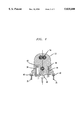
- FIG. 5 illustrates another embodiment of the apparatus for heating water according to the present invention wherein the heater is secured within the appliance housing;
- FIG. 6 illustrates a cross-section of the heater illustrated in FIG. 5 with its details more clearly illustrated.
- the apparatus for heating water of the present invention is generally designated by the reference character 10 and comprises water receptacle 12, means for heating said volume of water such as an electric heater 22, distancing means 26, and securement means 28.
- Heater 22 is shown in FIG. 1 in a secured and operable position when the apparatus 10 is to be operably used to perform its function of steaming and heating.
- Water receptacle 12, which may be of any shape or configuration, is provided with a bottom wall 14 and side walls 15 for retaining a volume of water 20 within its confines.
- Bottom wall 14 has an interior surface 16 proximate water 20 and an exterior surface 18.
- heater 22 comprises an electric heating element encased in an aluminum die cast cartridge, and is fully immersed in water 20 for heating the volume of water 20 within water receptacle 12.
- any type appliance that is suitable for use with an electric heater such as a distiller, humidifier or food steamer may be utilized although, the invention is not limited in this respect.
- heater 22 is further provided with a peripheral grooved portion 40 which is configured to receive distancing means 26 which distances heater 22 out of direct contact with interior surface 16 of bottom wall 14 within water receptacle 12.
- Distancing means 26 is advantageously a circular collar member of high temperature rubber, such as for example silicon rubber.
- the width of the distancing means 26, and thus the degree of distancing off and away from interior surface 16 of the bottom wall 14 is in the range of about 3/8 to 1/2 of an inch, although any suitable width may be utilized to achieve the purpose of distancing the heater 22 from bottom wall 14.
- the width of collar member 26 depends on the type and temperature intensity of the heater used.
- bottom wall 14 may be fabricated out of polypropylene plastic instead of more expensive P.P.S., P.B.T. or polycarbonate resins. Also as shown in FIG.
- a water reservoir as denoted by element 52, is provided which is substantially equal to the height of collar member 26.
- water reservoir 52 provides a high temperature water barrier the width of the collar member 26 between heater 22 and bottom wall 14.
- bottom wall 14 may be fabricated out of an inexpensive polypropylene plastic material.
- the water reservoir 52 prevents meltdown of bottom wall 14 of the water receptacle 12.
- securement pin 29 is inserted through an opening 46 in bottom wall 14 and into an engagement surface 48 contained within heater 22.
- securement pin 29 securely retains heater 22, collar member 26 to interior surface 16 of bottom wall 14.
- Securement pin 29 which may be a screw or any other form of attachment means, has a first end 30 and a second end 32 wherein first end 30 passes through opening 46 in bottom wall 14, preferably for threadable engagement with engagement surface 48 of heater 22.
- a washer or spoked cone 34 may be placed between exterior surface 18 of bottom wall 14 and the head of securement pin 29 so that when securement pin 29 is inserted through opening 46 of bottom wall 14 and when first end 30 of securement pin 29 is engaged with engagement surface 48 of heater 22, second end 32 of securement pin 29 contacts spoked cone 34 and retains spoked cone 34 in place against exterior surface 18 of bottom wall 14.
- collar member 26 is tightly fixed against interior surface 16 of bottom wall 14 to create a fluid tight seal between the volume of water 20 contained within water receptacle 12 and exterior surface 18 of bottom wall 14 of water receptacle 12. As shown in FIG.
- spoked cone 34 may advantageously be configured as an outer support ring 56 having a diameter substantially the same as the diameter of collar member 26, the spoked cone having spoked members 58 which extend downwardly at an angle of approximately 45 degrees towards the center of a central hub 60.
- Hub 60 includes an opening having a diameter that is slightly larger than the diameter of securement pin 29.
- heater 22 is provided with a first opening 36 for receiving a thermostat 42.
- Thermostat 42 is connected to heater 22 so that a heating element 54, as shown in FIG. 2, which is connected to electrical contacts 24 may be disengaged when a predetermined temperature is reached in order to avoid overheating such as when the water 20 in the water receptacle 12 is almost fully evaporated.
- Heater 22 is also provided with a second opening 38 to accommodate a thermofuse 44.
- Thermofuse 44 provides a second safety feature which backs up thermostat 42 in order to shut off heater 22 before water 20 is totally evaporated from the water receptacle 12 in the event the thermostat 42 malfunctions.
- FIGS. 5 and 6 illustrate an alternative embodiment of the electric heater according to the present invention.
- heater 100 includes an outer aluminum cylindrical enclosure 104, which encloses a PTC stone heating element 101, the PTC stone heating element 101 having opposing faces 118, 119, each face having a wire lead 102, 103 welded thereto for conduction of electricity to faces 118, 119.
- Heater 100 shown in greater detail in FIG. 6, further comprises a cap plate 105, preferably a flat piece of aluminum.
- Cap plate 105 has a threaded opening 106 in its center area, and has openings 107, 108 to each side of threaded opening 106, to permit wire leads 102, 103 to pass out from heater enclosure 104.
- Heater enclosure 104 is provided with flange portion 109 which overlaps the perimeter of cap plate 105 and is rolled over cap plate 105 to tightly hold cap plate 105 to heater 100.
- Flange 109 includes a rolled over portion 110 at its extreme which creates a peripheral grooved portion 120 about the cap plate 105.
- Collar member 111 for distancing heater 100 from interior surface 16 of bottom wall 14 of water receptacle 12 and which holds heater 100 in spaced alignment with interior surface 16 of bottom wall 14 of water receptacle 12 is disposed between interior surface 16 of bottom wall 14 of water receptacle 12 and cap plate 105 where it is received in grooved portion 120.
- Collar member 112 preferably a spoked cone, retains heater 100 to bottom wall 14 of water receptacle 12, by a screw 113 which passes through bottom wall 14 of water receptacle 12 and is received in threaded opening 106 in cap plate 105. Tightening screw 113 compresses collar member 111 to create a water-tight seal between heater flange 109 and interior surface 16 of bottom wall of receptacle 12.
- an electrically insulating but thermally conductive material 114 such as, for example, high temperature silicon rubber paste, is filled into void 121 between PTC stone and heater enclosure shell 104.
- Material 114 may be further loaded with a thermally conductive mass such as magnesium oxide grains which help transfer the heat from heater 101 to heater enclosure shell 104 and the surrounding water 20 (shown in FIG. 5).
- a first mica disk 115 is disposed therebetween.
Abstract
Description
Claims (17)
Priority Applications (1)
| Application Number | Priority Date | Filing Date | Title |
|---|---|---|---|
| US08/726,636 US5835680A (en) | 1996-10-07 | 1996-10-07 | Immersion heater and support structure |
Applications Claiming Priority (1)
| Application Number | Priority Date | Filing Date | Title |
|---|---|---|---|
| US08/726,636 US5835680A (en) | 1996-10-07 | 1996-10-07 | Immersion heater and support structure |
Publications (1)
| Publication Number | Publication Date |
|---|---|
| US5835680A true US5835680A (en) | 1998-11-10 |
Family
ID=24919399
Family Applications (1)
| Application Number | Title | Priority Date | Filing Date |
|---|---|---|---|
| US08/726,636 Expired - Fee Related US5835680A (en) | 1996-10-07 | 1996-10-07 | Immersion heater and support structure |
Country Status (1)
| Country | Link |
|---|---|
| US (1) | US5835680A (en) |
Cited By (15)
| Publication number | Priority date | Publication date | Assignee | Title |
|---|---|---|---|---|
| US6243535B1 (en) * | 1997-02-14 | 2001-06-05 | Ecovap S.A. | Steam generator |
| US6275652B1 (en) * | 1999-08-09 | 2001-08-14 | The Holmes Group, Inc. | Heating element for a humidifier |
| US6314237B1 (en) | 2000-05-16 | 2001-11-06 | Appliance Development Corporation | Vapor generator |
| US6473563B2 (en) * | 2000-12-01 | 2002-10-29 | Japan Pionics Co., Ltd. | Vaporizer and apparatus for vaporizing and supplying |
| US6560408B2 (en) | 2001-04-20 | 2003-05-06 | Appliance Development Corporation | Humidifier |
| US20040004299A1 (en) * | 2000-05-16 | 2004-01-08 | Glucksman Dov Z. | Apparatus for conditioning air |
| US20070186368A1 (en) * | 2006-02-10 | 2007-08-16 | Tennant Company | Cleaning apparatus having a functional generator for producing electrochemically activated cleaning liquid |
| US20090301521A1 (en) * | 2008-06-10 | 2009-12-10 | Tennant Company | Steam cleaner using electrolyzed liquid and method therefor |
| US8319654B2 (en) | 2008-06-19 | 2012-11-27 | Tennant Company | Apparatus having electrolysis cell and indicator light illuminating through liquid |
| US8337690B2 (en) | 2007-10-04 | 2012-12-25 | Tennant Company | Method and apparatus for neutralizing electrochemically activated liquids |
| US8603320B2 (en) | 2006-02-10 | 2013-12-10 | Tennant Company | Mobile surface cleaner and method for generating and applying an electrochemically activated sanitizing liquid having O3 molecules |
| US8719999B2 (en) | 2006-02-10 | 2014-05-13 | Tennant Company | Method and apparatus for cleaning surfaces with high pressure electrolyzed fluid |
| WO2014127538A1 (en) * | 2013-02-25 | 2014-08-28 | 广东万和电气有限公司 | Vertical electric water heater |
| US20150063791A1 (en) * | 2012-03-12 | 2015-03-05 | T.P.A. Impex S.P.A. | Boiler for Domestic Appliances and Water Heating Systems With Steam Production for Home and Industrial Use |
| US20150316252A1 (en) * | 2012-12-05 | 2015-11-05 | Coway Co., Ltd. | Steam generator |
Citations (7)
| Publication number | Priority date | Publication date | Assignee | Title |
|---|---|---|---|---|
| GB620384A (en) * | 1947-01-17 | 1949-03-23 | Oswald Adrian Mcdowell | Improvements in thermostatically controlled electric water heaters |
| US3283940A (en) * | 1964-10-21 | 1966-11-08 | Coates | Heater element fitting for pressurized tank |
| DE2951014A1 (en) * | 1978-12-22 | 1980-07-10 | Irca Spa | FASTENING DEVICE FOR HEATING EQUIPMENT |
| US4238666A (en) * | 1978-03-13 | 1980-12-09 | Pomper William R | Portable electric single service beverage heating device |
| US4263470A (en) * | 1978-08-30 | 1981-04-21 | Bulten-Kanthal Ab | Holding device for electrical resistance elements in furnaces |
| US5159659A (en) * | 1991-02-26 | 1992-10-27 | Robertshaw Controls Company | Hot water tank construction, electrically operated heating element construction therefor and methods of making the same |
| US5404803A (en) * | 1992-12-17 | 1995-04-11 | Appliance Development Corporation | Food steamer utensil |
-
1996
- 1996-10-07 US US08/726,636 patent/US5835680A/en not_active Expired - Fee Related
Patent Citations (7)
| Publication number | Priority date | Publication date | Assignee | Title |
|---|---|---|---|---|
| GB620384A (en) * | 1947-01-17 | 1949-03-23 | Oswald Adrian Mcdowell | Improvements in thermostatically controlled electric water heaters |
| US3283940A (en) * | 1964-10-21 | 1966-11-08 | Coates | Heater element fitting for pressurized tank |
| US4238666A (en) * | 1978-03-13 | 1980-12-09 | Pomper William R | Portable electric single service beverage heating device |
| US4263470A (en) * | 1978-08-30 | 1981-04-21 | Bulten-Kanthal Ab | Holding device for electrical resistance elements in furnaces |
| DE2951014A1 (en) * | 1978-12-22 | 1980-07-10 | Irca Spa | FASTENING DEVICE FOR HEATING EQUIPMENT |
| US5159659A (en) * | 1991-02-26 | 1992-10-27 | Robertshaw Controls Company | Hot water tank construction, electrically operated heating element construction therefor and methods of making the same |
| US5404803A (en) * | 1992-12-17 | 1995-04-11 | Appliance Development Corporation | Food steamer utensil |
Cited By (21)
| Publication number | Priority date | Publication date | Assignee | Title |
|---|---|---|---|---|
| US6243535B1 (en) * | 1997-02-14 | 2001-06-05 | Ecovap S.A. | Steam generator |
| US6275652B1 (en) * | 1999-08-09 | 2001-08-14 | The Holmes Group, Inc. | Heating element for a humidifier |
| US6314237B1 (en) | 2000-05-16 | 2001-11-06 | Appliance Development Corporation | Vapor generator |
| WO2001088442A1 (en) | 2000-05-16 | 2001-11-22 | Appliance Development Corporation | Vapor generator |
| US20040004299A1 (en) * | 2000-05-16 | 2004-01-08 | Glucksman Dov Z. | Apparatus for conditioning air |
| US6938886B2 (en) | 2000-05-16 | 2005-09-06 | Appliance Development Corporation | Apparatus for conditioning air |
| US6473563B2 (en) * | 2000-12-01 | 2002-10-29 | Japan Pionics Co., Ltd. | Vaporizer and apparatus for vaporizing and supplying |
| US6560408B2 (en) | 2001-04-20 | 2003-05-06 | Appliance Development Corporation | Humidifier |
| US8156608B2 (en) | 2006-02-10 | 2012-04-17 | Tennant Company | Cleaning apparatus having a functional generator for producing electrochemically activated cleaning liquid |
| US20070186368A1 (en) * | 2006-02-10 | 2007-08-16 | Tennant Company | Cleaning apparatus having a functional generator for producing electrochemically activated cleaning liquid |
| US8603320B2 (en) | 2006-02-10 | 2013-12-10 | Tennant Company | Mobile surface cleaner and method for generating and applying an electrochemically activated sanitizing liquid having O3 molecules |
| US8719999B2 (en) | 2006-02-10 | 2014-05-13 | Tennant Company | Method and apparatus for cleaning surfaces with high pressure electrolyzed fluid |
| US8337690B2 (en) | 2007-10-04 | 2012-12-25 | Tennant Company | Method and apparatus for neutralizing electrochemically activated liquids |
| US20090301521A1 (en) * | 2008-06-10 | 2009-12-10 | Tennant Company | Steam cleaner using electrolyzed liquid and method therefor |
| US8319654B2 (en) | 2008-06-19 | 2012-11-27 | Tennant Company | Apparatus having electrolysis cell and indicator light illuminating through liquid |
| US20150063791A1 (en) * | 2012-03-12 | 2015-03-05 | T.P.A. Impex S.P.A. | Boiler for Domestic Appliances and Water Heating Systems With Steam Production for Home and Industrial Use |
| US9702544B2 (en) * | 2012-03-12 | 2017-07-11 | T.P.A. Impex S.P.A. | Boiler for domestic appliances and water heating systems with steam production for home and industrial use |
| US20150316252A1 (en) * | 2012-12-05 | 2015-11-05 | Coway Co., Ltd. | Steam generator |
| US9958151B2 (en) * | 2012-12-05 | 2018-05-01 | Coway Co., Ltd. | Steam generator |
| WO2014127538A1 (en) * | 2013-02-25 | 2014-08-28 | 广东万和电气有限公司 | Vertical electric water heater |
| CN105026851A (en) * | 2013-02-25 | 2015-11-04 | 广东万和电气有限公司 | Vertical electric water heater |
Similar Documents
| Publication | Publication Date | Title |
|---|---|---|
| US5835680A (en) | Immersion heater and support structure | |
| US5203257A (en) | Food warming vessel for cafeterias, restaurants and the like | |
| US4700050A (en) | Heater clamping arrangement for electrically heated boilers | |
| US2977454A (en) | Electric immersion heater | |
| US3678246A (en) | Liquid heating vessel | |
| US2725460A (en) | Deep fat fryer | |
| CN109744899B (en) | Food preparation machine that heating efficiency is high | |
| US6314237B1 (en) | Vapor generator | |
| US2703358A (en) | Hot cup | |
| US3277277A (en) | Thermostatically controlled electric immersion heater unit | |
| GB2316229A (en) | Cordless liquid heating appliances | |
| JPH0317123Y2 (en) | ||
| US5345059A (en) | Temperature self-regulating, electrically-heated spoon | |
| KR200192151Y1 (en) | Heater using pct | |
| KR940010662B1 (en) | Humidifier using ptc heater | |
| US1913298A (en) | Electric liquid heating apparatus | |
| KR940007846Y1 (en) | Mounting device ptc material in humidifier | |
| KR100244807B1 (en) | Ceramic water-proof heater | |
| KR102255770B1 (en) | Overheat protection device of immersion heaters | |
| JPS6329458Y2 (en) | ||
| RU2244149C2 (en) | Device to warm up diesel fuel in fuel intake | |
| US1060263A (en) | Electrically-heated utensil. | |
| JPS626807B2 (en) | ||
| JPS588181Y2 (en) | electric cooker | |
| WO2005024300A2 (en) | Universal device for checking the water level in steam boilers |
Legal Events
| Date | Code | Title | Description |
|---|---|---|---|
| AS | Assignment |
Owner name: APPLIANCE DEVELOPMENT CORP., MASSACHUSETTS Free format text: ASSIGNMENT OF ASSIGNORS INTEREST;ASSIGNORS:GLUCKSMAN, DOV Z.;WEIDEMANN, KARL H.;REEL/FRAME:008263/0155 Effective date: 19960930 |
|
| REMI | Maintenance fee reminder mailed | ||
| FPAY | Fee payment |
Year of fee payment: 4 |
|
| SULP | Surcharge for late payment | ||
| AS | Assignment |
Owner name: GENERAL ELECTRIC CAPITAL CORPORATION, AS COLLATERA Free format text: SECURITY INTEREST IN LICENSED PATENTS;ASSIGNOR:THE HOLMES GROUP, INC.;REEL/FRAME:015209/0478 Effective date: 20040506 |
|
| REMI | Maintenance fee reminder mailed | ||
| LAPS | Lapse for failure to pay maintenance fees | ||
| STCH | Information on status: patent discontinuation |
Free format text: PATENT EXPIRED DUE TO NONPAYMENT OF MAINTENANCE FEES UNDER 37 CFR 1.362 |
|
| FP | Lapsed due to failure to pay maintenance fee |
Effective date: 20061110 |
|
| FEPP | Fee payment procedure |
Free format text: PETITION RELATED TO MAINTENANCE FEES FILED (ORIGINAL EVENT CODE: PMFP); ENTITY STATUS OF PATENT OWNER: SMALL ENTITY |
|
| FEPP | Fee payment procedure |
Free format text: PETITION RELATED TO MAINTENANCE FEES DISMISSED (ORIGINAL EVENT CODE: PMFS); ENTITY STATUS OF PATENT OWNER: SMALL ENTITY |