US5838793A - Controlling movement of owned parts - Google Patents
Controlling movement of owned parts Download PDFInfo
- Publication number
- US5838793A US5838793A US08/629,980 US62998096A US5838793A US 5838793 A US5838793 A US 5838793A US 62998096 A US62998096 A US 62998096A US 5838793 A US5838793 A US 5838793A
- Authority
- US
- United States
- Prior art keywords
- security code
- replaceable
- parts
- computer
- code
- Prior art date
- Legal status (The legal status is an assumption and is not a legal conclusion. Google has not performed a legal analysis and makes no representation as to the accuracy of the status listed.)
- Expired - Lifetime
Links
Images


Classifications
-
- G—PHYSICS
- G06—COMPUTING; CALCULATING OR COUNTING
- G06F—ELECTRIC DIGITAL DATA PROCESSING
- G06F21/00—Security arrangements for protecting computers, components thereof, programs or data against unauthorised activity
- G06F21/70—Protecting specific internal or peripheral components, in which the protection of a component leads to protection of the entire computer
- G06F21/88—Detecting or preventing theft or loss
-
- G—PHYSICS
- G06—COMPUTING; CALCULATING OR COUNTING
- G06F—ELECTRIC DIGITAL DATA PROCESSING
- G06F11/00—Error detection; Error correction; Monitoring
- G06F11/006—Identification
-
- G—PHYSICS
- G06—COMPUTING; CALCULATING OR COUNTING
- G06F—ELECTRIC DIGITAL DATA PROCESSING
- G06F2207/00—Indexing scheme relating to methods or arrangements for processing data by operating upon the order or content of the data handled
- G06F2207/72—Indexing scheme relating to groups G06F7/72 - G06F7/729
- G06F2207/7219—Countermeasures against side channel or fault attacks
-
- H—ELECTRICITY
- H01—ELECTRIC ELEMENTS
- H01L—SEMICONDUCTOR DEVICES NOT COVERED BY CLASS H10
- H01L2223/00—Details relating to semiconductor or other solid state devices covered by the group H01L23/00
- H01L2223/544—Marks applied to semiconductor devices or parts
- H01L2223/54433—Marks applied to semiconductor devices or parts containing identification or tracking information
- H01L2223/5444—Marks applied to semiconductor devices or parts containing identification or tracking information for electrical read out
Definitions
- the present invention relates to the field of computers and systems security. Specifically this invention is adapted to allow a system to function only with parts designated for that system, in order to prevent theft of replaceable computer parts.
- the conventional solution being used to try to control access to computer parts is to record serial numbers of the parts and the machines and, when doing maintenance on the machine, check the parts against what was in the machine initially.
- serial number tracking Another problem with serial number tracking is that parts are often moved from one machine to another by service personnel, and there is no history of the movement of the parts. Hence, it is impossible to tell if the parts have been stolen or simply misplaced. Also, nothing in this method prevents stolen parts from being used in different computer systems.
- the present invention is directed to an apparatus and method for controlling movement of owned computer parts.
- owned computer parts are identified such that they will only function in one or more computer systems identified to the same owner.
- the present apparatus invention comprises a non-volatile memory device located on each of a plurality of replaceable computer parts. Each non-volatile memory device contains a part security code field.
- the apparatus further comprises a non-volatile system memory device located on the computer system.
- the system memory device contains a system security code field.
- the apparatus further comprises a means for comparison of each part security code field and the system security code field, allowing the system to function with any particular one of the plurality of replaceable computer parts only if a value stored in the particular one part security code field is compatible with a value stored in the system security code field.
- the present invention provides a method for preventing theft of replaceable computer parts.
- This method includes the step of storing a part security code along with an enable bit in a non-volatile memory located on each of a plurality of replaceable computer parts.
- This method further includes the step of storing a system security code in a non-volatile computer system memory.
- the next step compares the part security codes with the system security code if the enable bit is set.
- the final step allows the computer system to function with any particular one of the plurality of replaceable computer parts only if the part security code of the particular one part is compatible with the system security code.
- this invention prevents theft of computer parts by allowing them to work only in computer systems which have a compatible security code with the part. There will be no incentive to steal parts if they are useless in other systems. In addition, if one owner has multiple systems, parts can be exchanged among these systems as long as the system security codes in the systems are compatible.
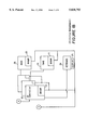
- FIG. 1 is a preferred embodiment of an apparatus showing a computer system
- FIG. 2 is a system view showing the use of a computer program to compare security codes of the system and security codes of the parts;
- FIG. 3 is an enlarged view of FIG. 2, showing an individual computer part and its memory for security code storage;
- FIG. 4 is a flow chart of a preferred method used to compare security code values
- FIG. 5 is a flow chart of a preferred method used to change the security code on a computer part or system, or to disable the security check for a given computer part or system.
- FIG. 1 is a preferred embodiment of the invention showing a block diagram of a computer system.
- This invention is directed to controlling the movement of owned computer parts, by preventing the use of computer parts in any system unless the security code of the part is compatible with the security code of the computer system.
- This invention in further embodiments, controls movement of owned parts in other systems, not limited to only computer systems.
- the codes must be compatible, this means that the system must recognize the code in the part in some manner.
- the codes of the part and the system must be the same to be compatible.
- the system control center for the security system shown is an operation panel 10.
- the operation panel 10 contains a microprocessor 36 and Read Only Memory 35 for sequencing the system power supplies on and off as well as controlling the configuration of the various devices attached to the system.
- the operation panel 10 has non-volatile memory 12.
- the non-volatile memory also holds a system enabling bit 14.
- the storage location for the system security code 13 preferably holds 8 to 16 bytes of data, but could hold any number of bytes.
- the storage location for the system enabling bit 14 is preferably a single bit, but could be any number of bits.
- operation panel 10 operates software contained in Read Only Memory 35 that executes on a microprocessor 36 to do the security checking and allows user control of security code values.
- Operation panel 10 typically interfaces to non-volatile memory 15 of all coded field replaceable units using a serial interface 11.
- other processor platforms can be used to control the security codes.
- field replaceable unit is a term used to refer to a computer part or group of parts which can be replaced.
- field replaceable units may include, but are not limited to, a Central Processing Unit (CPU) 16, one or more memory cards or units 17, one or more Input/Output (I/O) controller cards or units 18, one or more hard disk units 20, and one or more tape storage units 19.
- CPU Central Processing Unit
- I/O Input/Output
- Each coded field replaceable unit contains non-volatile memory 15 for storing a field replaceable unit security code 44, as shown in FIG. 3.
- the non-volatile memory locations 15 also stores a field replaceable unit enabling bit 46.
- FIG. 2 shows a block diagram of an alternative computer system embodying the invention.
- Software in Read Only Memory 35 controls the apparatus by means of the microprocessor 36 through a serial interface 11 with the system non-volatile memory 12 containing the system security code 13 and enabling bit 14, and with the field replaceable unit's non-volatile memory.
- Field replaceable units are shown generically. Some field replaceable units 32 with non-volatile memory 15 reside within the system housing 30, and some field replaceable units 52 with non-volatile memory 15 reside in external cabinets 50.
- FIG. 3 is an enlarged view of a generic field replaceable unit 40. This is representative of all field replaceable units mentioned above.
- the field replaceable unit contains non-volatile memory 15. In a hard disk storage unit 20 of FIG. 1, this non-volatile memory simply may be designated storage on the disk. Other field replaceable units however may require additional storage area for this purpose, in which case Flash or Electrically Erasable Programmable Read Only Memory storage or similar memory is suitable, but not exclusively required.
- the non-volatile memory 15 has locations shown for the field replaceable unit's security code 44. In an alternative embodiment, the non-volatile memory 15 also has a location for a field replaceable unit enabling bit 46.
- the security code location 44 preferably stores 8 to 16 bytes of information, but could store any number of bytes.
- the enabling bit location is usually, but not necessarily, adjacent to the security code location 44, and consists preferably of one bit of storage but could consist of any number of bits of storage.
- FIG. 4 shows a flow diagram for software used in one embodiment of the method for comparing security codes.
- This embodiment utilizes enabling bits on the field replaceable units, which may be used to disable the security for a particular part, so that a part may be temporarily loaned to a system with a different security code.
- This software shown in FIG. 4 checks the security code of all field replaceable units in the system, obtained via serial interface 11, so that units with improper values of the security code, such as stolen units, cannot function in the system.
- the method begins with start step 60, which is activated upon powering up the system or upon adding a field replaceable unit, which often is appropriate since modern computer systems allow hot-plugging, or addition/replacement of computer parts, while the system is powered on.
- decision step 62 which checks a field replaceable unit 40 to determine whether the enabling bit 46 on that particular unit's non-volatile memory 15 is set. If the enabling bit 46 on the unit is not set, the field replaceable unit will function with this or any system, as shown in step 64. The security check for the unit will thus be bypassed, and the next field replaceable unit, if any exist, will be checked in step 72.
- the software will compare the system security code 13 found in non-volatile memory 12 with the field replaceable unit security code 44, shown at decision step 66. If the field replaceable unit security code 44 is not compatible with the system security code 13, this field replaceable unit 40 will not be identified to or configured in the system, as shown in step 68. Therefore, this field replaceable unit will not function with this system and the software next checks additional field replaceable units in step 72.
- step 70 If the field replaceable unit security code 44 is compatible with the system security code 13, this field replaceable unit 40 will be identified to the system and will function properly for its intended purpose in this system, as shown in step 70.
- the software checks in decision step 72 to determine if any additional field replaceable units exist and are connected to the system. If not, the program ends at step 76. If additional field replaceable units exist, the program proceeds along flow line 74 to return to step 62, where the additional field replaceable units are examined in the above manner. In this way, all of the field replaceable units attached to the system can be checked, which is an advantageous aspect of the invention in such a preferred embodiment.
- FIG. 5 shows a flow diagram for software used as an embodiment of the method for controlling the security check.
- the software to change the security features is partially executed in the Central Processing Unit 16 of FIG. 1 and partially in the operation panel software in the Read Only Memory 35.
- the software in the Central Processing Unit 16 would present a screen interface to a display 25 to allow the user to change the security features.
- the screen interface to the display 25 would allow the user to select the removable field replaceable unit 40 whose security field is to be changed, select whether the security field is to be enabled or disabled on the field replaceable unit 40, and allow the system security field to be altered.
- a keyboard 24 is used to allow the user the ability to enter old or new security codes or to select the removable field replaceable unit 40 to operate upon.
- the security code can be altered in many different ways, for example: through a communication link, through a tape, diskette, compact disk Read Only Memory, or any medium capable of storing the old and new codes.
- a communication link through a tape, diskette, compact disk Read Only Memory, or any medium capable of storing the old and new codes.
- a tape diskette
- compact disk Read Only Memory or any medium capable of storing the old and new codes.
- use of the keyboard and display for this task is the preferred embodiment.
- the software code running in the Central Processing Unit 16 will pass the requirements to the operation panel code in the Read Only Memory 35 where the security checks will be done.
- This feature of user changeability of the codes allows the user, usually the owner of the computer system, to control the system security (1) by enabling or disabling the security checks for each individual field replaceable unit, or (2) by changing the security code for the system itself.
- the method begins at start step 80 and proceeds to step 82, where the user is prompted to enter the current system security code, wherein the initial security code may be provided by the manufacturer.
- the security code entered by the user is compared with the system security code 13 stored in the system non-volatile memory 12. If the code entered by the user is not compatible with that stored in the system, the program ends at step 110. Thus, no unauthorized user, or user without knowledge of the proper security code, is allowed access to the control of the security check apparatus.
- step 86 the user is prompted at step 86 with the choice of whether to change the system security code 13. This option would be taken only if all of the field replaceable unit security codes are disabled first, because if the system security code 13 is not compatible with the replaceable part security code 44, the replaceable part security code 44 cannot be altered and the replaceable unit will not work. If the user chooses to do so, they are allowed to change the code by entering it from the keyboard 24 at step 88. After this change is complete, or if the user decides not to change the system security code 13, the program proceeds to step 90, where the user is asked whether or not a field replaceable unit security code is to be changed. If no field replaceable unit is to be changed, the program ends at step 110.
- step 92 the software checks to see if the identified field replaceable unit is identified to the system. If no such field replaceable unit exists, the change cannot be executed, and the program returns to step 90 to allow the user to choose a different field replaceable unit, if desired. If the field replaceable unit enabling bit 46 is not set in step 95, then the code goes to step 98.
- step 96 checks the identified field replaceable unit to determine whether the security code 44 on the identified unit 40 is compatible with the security code 13 on the system. If these are not compatible, the user is not allowed to change the security code or enabling bit on this field replaceable unit, and the program returns to step 90 to prompt for other field replaceable units to be changed.
- the user may alter the enabling bit 46 of the identified field replaceable unit 40 at step 100 if at step 98 the user chooses to do so.
- the system security code 13 is copied into the security code field 44 on the identified field replaceable unit 40.
- the program returns to step 90, and the user is prompted for additional field replaceable units to change, if any are desired.
- system security code 13 may be stored in the operation panel non-volatile memory 12, and the system enabling bit 14 is set.
- Each field replaceable unit that was to be enabled would have a compatible system security code stored in its non-volatile memory 42 with its enable bit 46 set.
- the location where the system security code resides is either fixed in the operation panel 10 or in the security code field 44 in each field replaceable unit 40. If separately stored in each field replaceable unit 40, a voting mechanism could be used, such as two-out-of-three match, to determine the correct system security code 13.
- a sequence field 200 is included as shown in FIG. 3. The sequence field 200 is used to keep track of the number of times the system security code 13 is written into a security code field 44 of a field replaceable unit. The voting mechanism would then include the sequence field 200 and the security code field 44, as both must be the same in two of the three voting units. If a majority vote occurs, the system security code 13 is written into the non-matching parts, and the sequence field 200 of all parts is incremented by one.
- this embodiment prevents the propagation of the system security code 13 into other systems, which would circumvent the security system. Further, this embodiment deals with the situation of replacing the non-volatile system memory device 12, such as when the entire op panel 10 is replaced.
- the data stored in non-volatile memory of the system and field replaceable units may be stored so as to prevent discovery or tampering. If the data is kept in a clear text form, it is easy to copy or alter.
- the data stored is encrypted data, as that term is disclosed and used in pending U.S. application Ser. No. 08/322,246, METHOD AND APPARATUS FOR VALIDATING SYSTEM OPERATION, filed Oct. 12, 1994, by the assignee.
- the cited applications discloses an electronic signature stored with the data. Other data protection means are envisioned, so that the method disclosed in the cited application is not the exclusive means for this task.
- encryption of data or placing an electronic signature with the data is not a requirement of every embodiment of the present invention.
Abstract
Description
Claims (18)
Priority Applications (1)
| Application Number | Priority Date | Filing Date | Title |
|---|---|---|---|
| US08/629,980 US5838793A (en) | 1996-04-09 | 1996-04-09 | Controlling movement of owned parts |
Applications Claiming Priority (1)
| Application Number | Priority Date | Filing Date | Title |
|---|---|---|---|
| US08/629,980 US5838793A (en) | 1996-04-09 | 1996-04-09 | Controlling movement of owned parts |
Publications (1)
| Publication Number | Publication Date |
|---|---|
| US5838793A true US5838793A (en) | 1998-11-17 |
Family
ID=24525269
Family Applications (1)
| Application Number | Title | Priority Date | Filing Date |
|---|---|---|---|
| US08/629,980 Expired - Lifetime US5838793A (en) | 1996-04-09 | 1996-04-09 | Controlling movement of owned parts |
Country Status (1)
| Country | Link |
|---|---|
| US (1) | US5838793A (en) |
Cited By (18)
| Publication number | Priority date | Publication date | Assignee | Title |
|---|---|---|---|---|
| US5982894A (en) * | 1997-02-06 | 1999-11-09 | Authentec, Inc. | System including separable protected components and associated methods |
| US6032257A (en) * | 1997-08-29 | 2000-02-29 | Compaq Computer Corporation | Hardware theft-protection architecture |
| EP1197826A1 (en) * | 2000-09-18 | 2002-04-17 | Kabushiki Kaisha Toshiba | Secured portable electronic device |
| US6487646B1 (en) | 2000-02-29 | 2002-11-26 | Maxtor Corporation | Apparatus and method capable of restricting access to a data storage device |
| US6490667B1 (en) | 2000-09-18 | 2002-12-03 | Kabushiki Kaisha Toshiba | Portable electronic medium |
| US20030065927A1 (en) * | 2001-09-28 | 2003-04-03 | Penner Miles J. | Method and apparatus for copy protecting hardware devices |
| US20030105961A1 (en) * | 2001-11-30 | 2003-06-05 | Peter Zatloukal | Avoiding attachment of an ineligible smart interchangeable cover to an electronic device |
| US6629061B1 (en) * | 2000-07-31 | 2003-09-30 | Avaya Technology Corp. | Automatic concealment of product serialization information |
| US20040044903A1 (en) * | 2002-08-08 | 2004-03-04 | Nec Viewtechnology, Ltd. | Electric equipment, and method and program for preventing unauthorized use of same |
| US6704678B2 (en) | 2002-05-31 | 2004-03-09 | Avaya Technology Corp. | Method and apparatus for downloading correct software to an electrical hardware platform |
| US20040252642A1 (en) * | 2003-06-12 | 2004-12-16 | Larson Thane M. | Method of overflow recovery of I2C packets on an I2C router |
| US20070077915A1 (en) * | 2005-09-30 | 2007-04-05 | Black Greg R | Method and apparatus for module authentication |
| US20080133941A1 (en) * | 2006-11-30 | 2008-06-05 | Texas Instruments Incorporated | Apparatus and method for frustrating unwanted access to data stored with a host device |
| US7548643B2 (en) | 1998-09-11 | 2009-06-16 | Digimarc Corporation | Methods, objects and apparatus employing machine readable data |
| US7606364B1 (en) | 2002-04-23 | 2009-10-20 | Seagate Technology Llc | Disk drive with flexible data stream encryption |
| US20100270916A1 (en) * | 2009-04-28 | 2010-10-28 | Universal Display Corporation | Iridium complex with methyl-d3 substitution |
| US20110107120A1 (en) * | 2009-11-02 | 2011-05-05 | Sony Corporation | Information processing apparatus, power supply control method, program and power supply control system |
| US20110102136A1 (en) * | 2009-11-02 | 2011-05-05 | Sony Corporation | Information processing apparatus, power-supply control method, program, and power-supply control system |
Citations (9)
| Publication number | Priority date | Publication date | Assignee | Title |
|---|---|---|---|---|
| US5006843A (en) * | 1988-12-01 | 1991-04-09 | Werner Hauer | Security module to preclude unauthorized users to operate motor driven equipment and to protect valuable parts of the motor from unauthorized exchange |
| US5229648A (en) * | 1989-08-10 | 1993-07-20 | Autosafe International, Inc. | Multi element security system |
| US5237609A (en) * | 1989-03-31 | 1993-08-17 | Mitsubishi Denki Kabushiki Kaisha | Portable secure semiconductor memory device |
| US5245330A (en) * | 1990-09-17 | 1993-09-14 | U.S. Philips Corporation | Microprocessor-controlled apparatus with improved disabling |
| US5267311A (en) * | 1992-12-08 | 1993-11-30 | Bakhoum Ezzat G | Intelligent diskette for software protection |
| US5297268A (en) * | 1988-06-03 | 1994-03-22 | Dallas Semiconductor Corporation | ID protected memory with a readable/writable ID template |
| US5510992A (en) * | 1994-01-03 | 1996-04-23 | Post N Mail, L.C. | System and method for automatically printing postage on mail |
| US5606507A (en) * | 1994-01-03 | 1997-02-25 | E-Stamp Corporation | System and method for storing, retrieving and automatically printing postage on mail |
| US5686759A (en) * | 1995-09-29 | 1997-11-11 | Intel Corporation | Integrated circuit package with permanent identification of device characteristics and method for adding the same |
-
1996
- 1996-04-09 US US08/629,980 patent/US5838793A/en not_active Expired - Lifetime
Patent Citations (9)
| Publication number | Priority date | Publication date | Assignee | Title |
|---|---|---|---|---|
| US5297268A (en) * | 1988-06-03 | 1994-03-22 | Dallas Semiconductor Corporation | ID protected memory with a readable/writable ID template |
| US5006843A (en) * | 1988-12-01 | 1991-04-09 | Werner Hauer | Security module to preclude unauthorized users to operate motor driven equipment and to protect valuable parts of the motor from unauthorized exchange |
| US5237609A (en) * | 1989-03-31 | 1993-08-17 | Mitsubishi Denki Kabushiki Kaisha | Portable secure semiconductor memory device |
| US5229648A (en) * | 1989-08-10 | 1993-07-20 | Autosafe International, Inc. | Multi element security system |
| US5245330A (en) * | 1990-09-17 | 1993-09-14 | U.S. Philips Corporation | Microprocessor-controlled apparatus with improved disabling |
| US5267311A (en) * | 1992-12-08 | 1993-11-30 | Bakhoum Ezzat G | Intelligent diskette for software protection |
| US5510992A (en) * | 1994-01-03 | 1996-04-23 | Post N Mail, L.C. | System and method for automatically printing postage on mail |
| US5606507A (en) * | 1994-01-03 | 1997-02-25 | E-Stamp Corporation | System and method for storing, retrieving and automatically printing postage on mail |
| US5686759A (en) * | 1995-09-29 | 1997-11-11 | Intel Corporation | Integrated circuit package with permanent identification of device characteristics and method for adding the same |
Cited By (30)
| Publication number | Priority date | Publication date | Assignee | Title |
|---|---|---|---|---|
| US5982894A (en) * | 1997-02-06 | 1999-11-09 | Authentec, Inc. | System including separable protected components and associated methods |
| US6032257A (en) * | 1997-08-29 | 2000-02-29 | Compaq Computer Corporation | Hardware theft-protection architecture |
| US7548643B2 (en) | 1998-09-11 | 2009-06-16 | Digimarc Corporation | Methods, objects and apparatus employing machine readable data |
| US8000518B2 (en) | 1998-09-11 | 2011-08-16 | Digimarc Corporation | Methods, objects and apparatus employing machine readable data |
| US6487646B1 (en) | 2000-02-29 | 2002-11-26 | Maxtor Corporation | Apparatus and method capable of restricting access to a data storage device |
| US6629061B1 (en) * | 2000-07-31 | 2003-09-30 | Avaya Technology Corp. | Automatic concealment of product serialization information |
| US6490667B1 (en) | 2000-09-18 | 2002-12-03 | Kabushiki Kaisha Toshiba | Portable electronic medium |
| EP1197826A1 (en) * | 2000-09-18 | 2002-04-17 | Kabushiki Kaisha Toshiba | Secured portable electronic device |
| US20030065927A1 (en) * | 2001-09-28 | 2003-04-03 | Penner Miles J. | Method and apparatus for copy protecting hardware devices |
| US20030105961A1 (en) * | 2001-11-30 | 2003-06-05 | Peter Zatloukal | Avoiding attachment of an ineligible smart interchangeable cover to an electronic device |
| WO2003048938A1 (en) * | 2001-11-30 | 2003-06-12 | Wildseed, Ltd. | Counterfeit avoidance attachment of a smart interchangeable cover to an electronic device |
| US7606364B1 (en) | 2002-04-23 | 2009-10-20 | Seagate Technology Llc | Disk drive with flexible data stream encryption |
| US6704678B2 (en) | 2002-05-31 | 2004-03-09 | Avaya Technology Corp. | Method and apparatus for downloading correct software to an electrical hardware platform |
| US20040044903A1 (en) * | 2002-08-08 | 2004-03-04 | Nec Viewtechnology, Ltd. | Electric equipment, and method and program for preventing unauthorized use of same |
| US7512992B2 (en) * | 2002-08-08 | 2009-03-31 | Nec Display Solutions, Ltd. | Electric equipment, and method and program for preventing unauthorized use of same |
| US20040252642A1 (en) * | 2003-06-12 | 2004-12-16 | Larson Thane M. | Method of overflow recovery of I2C packets on an I2C router |
| US7630304B2 (en) * | 2003-06-12 | 2009-12-08 | Hewlett-Packard Development Company, L.P. | Method of overflow recovery of I2C packets on an I2C router |
| WO2007040945A3 (en) * | 2005-09-30 | 2007-07-26 | Motorola Inc | Method and apparatus for module authentication |
| WO2007040945A2 (en) * | 2005-09-30 | 2007-04-12 | Motorola Inc. | Method and apparatus for module authentication |
| US20070077915A1 (en) * | 2005-09-30 | 2007-04-05 | Black Greg R | Method and apparatus for module authentication |
| US20080133941A1 (en) * | 2006-11-30 | 2008-06-05 | Texas Instruments Incorporated | Apparatus and method for frustrating unwanted access to data stored with a host device |
| US7711949B2 (en) * | 2006-11-30 | 2010-05-04 | Texas Instruments Incorporated | Apparatus and method for frustrating unwanted access to data with a host device |
| US20100270916A1 (en) * | 2009-04-28 | 2010-10-28 | Universal Display Corporation | Iridium complex with methyl-d3 substitution |
| US20110107120A1 (en) * | 2009-11-02 | 2011-05-05 | Sony Corporation | Information processing apparatus, power supply control method, program and power supply control system |
| US20110102136A1 (en) * | 2009-11-02 | 2011-05-05 | Sony Corporation | Information processing apparatus, power-supply control method, program, and power-supply control system |
| CN102054144A (en) * | 2009-11-02 | 2011-05-11 | 索尼公司 | Information processing apparatus, power-supply control method, program, and power-supply control system |
| US8527784B2 (en) | 2009-11-02 | 2013-09-03 | Sony Corporation | Information processing apparatus, power supply control method, program and power supply control system to define processing depending on types of power supply apparatus connected |
| US8547204B2 (en) * | 2009-11-02 | 2013-10-01 | Sony Corporation | Information processing apparatus, power-supply control method, program, and power supply control system |
| CN102054144B (en) * | 2009-11-02 | 2014-01-22 | 索尼公司 | Information processing apparatus, power-supply control method and power-supply control system |
| US8745422B2 (en) | 2009-11-02 | 2014-06-03 | Sony Corporation | Power supply control method, program and power supply control system capable of exercising power supply control based on the type of a connected power supply apparatus |
Similar Documents
| Publication | Publication Date | Title |
|---|---|---|
| US5838793A (en) | Controlling movement of owned parts | |
| US6012145A (en) | Security system for hard disk drive | |
| JP2755828B2 (en) | Secure application card for sharing application data and procedures between multiple microprocessors | |
| US7111321B1 (en) | Portable computer system with hierarchical and token-based security policies | |
| US5892906A (en) | Apparatus and method for preventing theft of computer devices | |
| EP0558222B1 (en) | Personal computer system with security features and method | |
| US5542044A (en) | Security device for a computer, and methods of constructing and utilizing same | |
| US6286102B1 (en) | Selective wireless disablement for computers passing through a security checkpoint | |
| US6487646B1 (en) | Apparatus and method capable of restricting access to a data storage device | |
| US5432939A (en) | Trusted personal computer system with management control over initial program loading | |
| US5287519A (en) | LAN station personal computer system with controlled data access for normal and unauthorized users and method | |
| CA2325712C (en) | Rfid tagging system for network assets | |
| US5341422A (en) | Trusted personal computer system with identification | |
| US5970227A (en) | Wireless proximity detector security feature | |
| US5805800A (en) | Apparatus and method for controlling storage medium using security capabilities | |
| CA1211542A (en) | Security arrangement for and method of rendering microprocessor-controlled electronic equipment inoperative after occurrence of disabling event | |
| US5771287A (en) | Apparatus and method for secured control of feature set of a programmable device | |
| US5265163A (en) | Computer system security device | |
| US6026492A (en) | Computer system and method to disable same when network cable is removed | |
| JP3671196B2 (en) | Pre-boot security controller | |
| NO309887B1 (en) | Secure memory card | |
| JPH0752389B2 (en) | Computer software usage control device | |
| JPH1083363A (en) | Game program supply system and program rewriting system | |
| US5946497A (en) | System and method for providing microprocessor serialization using programmable fuses | |
| JPS6210745A (en) | Method and apparatus for controlling access to memory |
Legal Events
| Date | Code | Title | Description |
|---|---|---|---|
| AS | Assignment |
Owner name: INTERNATIONAL BUSINESS MACHINES CORPORATION, NEW Y Free format text: ASSIGNMENT OF ASSIGNORS INTEREST;ASSIGNOR:LEWIS, DAVID OTTO;REEL/FRAME:007957/0492 Effective date: 19960403 |
|
| STCF | Information on status: patent grant |
Free format text: PATENTED CASE |
|
| FPAY | Fee payment |
Year of fee payment: 4 |
|
| AS | Assignment |
Owner name: LENOVO (SINGAPORE) PTE LTD.,SINGAPORE Free format text: ASSIGNMENT OF ASSIGNORS INTEREST;ASSIGNOR:INTERNATIONAL BUSINESS MACHINES CORPORATION;REEL/FRAME:016891/0507 Effective date: 20050520 Owner name: LENOVO (SINGAPORE) PTE LTD., SINGAPORE Free format text: ASSIGNMENT OF ASSIGNORS INTEREST;ASSIGNOR:INTERNATIONAL BUSINESS MACHINES CORPORATION;REEL/FRAME:016891/0507 Effective date: 20050520 |
|
| REMI | Maintenance fee reminder mailed | ||
| FPAY | Fee payment |
Year of fee payment: 8 |
|
| SULP | Surcharge for late payment |
Year of fee payment: 7 |
|
| FPAY | Fee payment |
Year of fee payment: 12 |
|
| AS | Assignment |
Owner name: LENOVO PC INTERNATIONAL, HONG KONG Free format text: NUNC PRO TUNC ASSIGNMENT;ASSIGNOR:LENOVO (SINGAPORE) PTE LTD.;REEL/FRAME:037160/0001 Effective date: 20130401 |