US5839157A - Street sweeper pick-up head - Google Patents
Street sweeper pick-up head Download PDFInfo
- Publication number
- US5839157A US5839157A US08/642,196 US64219696A US5839157A US 5839157 A US5839157 A US 5839157A US 64219696 A US64219696 A US 64219696A US 5839157 A US5839157 A US 5839157A
- Authority
- US
- United States
- Prior art keywords
- pick
- upper section
- suction chamber
- head
- nozzle assembly
- Prior art date
- Legal status (The legal status is an assumption and is not a legal conclusion. Google has not performed a legal analysis and makes no representation as to the accuracy of the status listed.)
- Expired - Lifetime
Links
Images


Classifications
-
- E—FIXED CONSTRUCTIONS
- E01—CONSTRUCTION OF ROADS, RAILWAYS, OR BRIDGES
- E01H—STREET CLEANING; CLEANING OF PERMANENT WAYS; CLEANING BEACHES; DISPERSING OR PREVENTING FOG IN GENERAL CLEANING STREET OR RAILWAY FURNITURE OR TUNNEL WALLS
- E01H1/00—Removing undesirable matter from roads or like surfaces, with or without moistening of the surface
- E01H1/08—Pneumatically dislodging or taking-up undesirable matter or small objects; Drying by heat only or by streams of gas; Cleaning by projecting abrasive particles
- E01H1/0827—Dislodging by suction; Mechanical dislodging-cleaning apparatus with independent or dependent exhaust, e.g. dislodging-sweeping machines with independent suction nozzles ; Mechanical loosening devices working under vacuum
- E01H1/0836—Apparatus dislodging all of the dirt by suction ; Suction nozzles
Definitions
- the present invention relates to street sweepers and, more particularly, to street sweepers that utilize a vacuum pick up head.
- conventional vacuum street sweepers and the like typically use at least one and preferably two side rotary brushes and a vacuum pick-up head corresponding to each rotary brush.
- the side brushes dislodge and sweep the debris such as dirt, leaves, gravel and the like between the wheels, into the center and along the longitudinal axis of the sweeper, so that the vacuum pick-up head can convey the debris into a collection hopper.
- a vacuum street sweeper is the WHIRLWIND brand vacuum street sweeper of Elgin Sweeper Company, a subsidiary of Federal Signal Corporation of Elgin, Ill.
- the pick-up head has a nozzle assembly for receiving and conveying the debris to a suction tube and ultimately to a collection hopper.
- the nozzle assembly typically has three sections--a lower or suction chamber, a middle section, and an upper section.
- the lower suction chamber or pick-up head chamber is a generally rectangular box-like chamber defined by front and rear inlets and lateral skid plates. Air is generally introduced into the suction chamber through the front and rear inlets. As the street sweeper moves forward, the nozzle assembly receives the debris through the front inlet at a speed generally equal to the forward velocity of the sweeper and the front air intake speed. The incoming rear inlet air acts to slow the debris from passing through the rear of the suction chamber in order to permit the vacuum the opportunity to pick-up the debris.
- the top of the suction chamber is joined to a middle section which is generally in the shape of a pyramidal frustum.
- the top of the middle section is joined to the third section which is a rectangular to circular transition member adapted to matingly attach to the suction tube.
- the suction tube is internally reinforced, typically with a helical wire or the like, to prevent the suction tube from collapsing in response to the vacuum exerted by the impeller fan located downstream of the collection hopper.
- a support assembly is attached to the nozzle assembly for supporting the nozzle assembly during the vacuum operation and movement of the vehicle.
- the support assembly typically includes a linkage assembly attached between the front of the nozzle and the sweeper frame for pulling the nozzle assembly and a wheel assembly supporting the rear of the nozzle assembly.
- One object of the present invention is to provide a street sweeper having increased effectiveness and efficiency which would provide better collection of debris from a street or surface.
- Another object is to provide a street sweeper which minimizes the noise level due to the pick-up head.
- a further object of the present invention is to provide an improved and more efficient pick-up head which permits the street sweeper to maximize the effectiveness of the fan.
- a related object is to provide an improved suction tube which minimizes noise and increases efficiency.
- Still another object of the present invention is to provide a pick-up head which may be efficiently manufactured using minimal components and efficient aerodynamic shapes.
- Another object of the present invention is to provide a pick-up head which minimizes damage by uneven ground surfaces or objects protruding from the ground surface.
- FIG. 1 is a side elevational view of a street sweeper having a vacuum pick-up head and a suction tube in accordance with the present invention
- FIG. 2 is a perspective view of the vacuum pick-up head shown in FIG. 1;
- FIG. 3 is a side elevational view of the vacuum pick-up head shown in FIG. 1;
- FIG. 4 is a front elevational view of the vacuum pick-up head shown in FIG. 1;
- FIG. 5 is a perspective view of the nozzle assembly
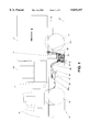
- FIG. 6 is a cross-sectional view of the nozzle assembly taken along line 6--6 of FIG. 4;
- FIG. 7 is a side elevational view of a conventional pick-up head
- FIG. 8 is a front elevational view of the pick-up head shown in FIG. 7;
- FIG. 9 is a stagnation streamline contour of an illustrative pick-up head.
- FIG. 10 is a cross-sectional view of a suction tube in accordance with the present invention.
- the street sweeper 10 having a vacuum pick-up head 12 in accordance with the present invention.
- the street sweeper 10 comprises a standard truck chassis 13 carrying a cab 14, wheels 16, at least one, and preferably two conventional rotary side brushes 18, and a fan or air suction pump 20 which directs debris from the pick-up head 12 into a suction tube 21 and a collection hopper 22.
- the side brushes 18 may be rotated either clockwise or counter-clockwise by conventional hydraulic actuators 24 in order to dislodge and sweep debris such as dirt, leaves, gravel and the like between the wheels 16, into the center and along the longitudinal axis of the sweeper 10.
- the direction of the sweeper 10 is indicated by the arrow designated V.
- the brushes 18 are also pivotally attached to the chassis 13 so that a conventional brush linkage assembly 26 can lower or raise the brushes 18 for sweeping or high speed travel from site to site.
- the linkage assembly 26 can regulate the pressure of the brushes 18 in order to accommodate debris of different sizes and types such as leaves, gravel, rocks or the like.
- the brushes 18 are also pivotally mounted so that the linkage assembly 26 can swing the brushes to the sides of the sweeper 10 in order to adjust the width of the path to be cleaned by the sweeper 10.
- the bristles of the brushes 18 may be made of any suitable material which is durable such as steel or polyurethane.
- the debris is transported into a collection hopper 22.
- the collection hopper 22 may be emptied into a dump truck for later disposal or the sweeper 10 may travel to a dumping area where the collection hopper 22 may be emptied.
- FIGS. 7-8 illustrate a conventional vacuum pick-up head 100 typically used in vacuum street sweepers such the WHIRLWIND brand vacuum street sweeper made by Elgin Sweeper Company in Elgin, Ill.
- This pick-up head 100 typically has a nozzle assembly generally referenced as 102 suspended above the ground surface S by a support assembly 104.
- the support assembly 104 comprises a linkage assembly 106 attached to the front of the nozzle assembly 102 and the chassis 13 and a caster assembly 108 attached to the rear of the nozzle assembly 102.
- the nozzle assembly 102 may have rigid attachment members 106b, 108b to facilitate attachment to the linkage and caster assemblies 106, 108, respectively.
- the attachment member 108b at the rear of the nozzle assembly 102 is pivotally attached to the chassis 13 by a chain 109 and a conventional lifting actuator (not shown) in a known manner to permit the pick-up head 100 to be lowered and raised.
- the nozzle end 106a of the linkage assembly 106 is rigidly attached to the attachment member 106b to permit the nozzle assembly 102 to be pulled by the sweeper 10.
- the caster assembly 108 typically comprises a caster 108a or other type of wheel rearwardly spaced from the nozzle assembly 102.
- the conventional support assembly 104 does not sufficiently protect the nozzle assembly 102 from damage when the sweeper 10 encounters uneven roadway surfaces such train tracks, manhole covers, cracks in the roadway and the like. Attempts to prevent such damage by having the lifting actuator (not shown) raise the nozzle assembly 102 above the surface S are inconvenient and unsatisfactory.
- Conventional skid plates 117 are connected by a plurality of nuts and bolts or the like (not shown) to the side walls 119 of the suction chamber 102a to hold the pick-up head 100 a predetermined distance above the surface S.
- the bottom of the skid plates 117 are typically made of a flexible yet durable material such as rubber which slidably engage the ground surface.
- the skid plates 117 and flexible flaps 114 disposed along the periphery of the suction chamber 102a have been used to minimize damage to the nozzle assembly 102, they permit infiltration of air into the lower section 102a of the nozzle assembly 102 which decreases the effectiveness of the nozzle section 102 and, ultimately, the efficiency of the fan 20.
- the conventional nozzle assembly 102 has front and rear inlets 112, 114 and an upper outlet 116 disposed between the nozzle assembly and a conventional suction tube 120 which communicates with a collection hopper 22 and fan 20 located downstream of the suction tube 120.
- the nozzle assembly 102 has lower, middle and upper sections generally referenced as 102a, 102b, 102c, respectively.
- the lower section 102a sometimes referred to as a pick-up chamber or suction chamber, comprises an elongated, box-like chamber which is generally defined by opposing side walls 119, the front and rear inlets 112, 114, and a top plate 121.
- the width of the suction chamber 102a is limited by the sweeper width, typically about 30 inches.
- the fan 20 creates a vacuum in the suction chamber 102a which draws air in through the front and rear inlets 112, 114. Referring to FIG. 8, the front inlet 112 is narrower than the suction chamber 102a.
- the nozzle assembly 102 receives the debris through the front inlet 112 at a velocity generally equal to the street sweeper speed and the inlet air velocity.
- the size of the front inlet 112 may be adjusted by a damper 118 pivotally attached to the top plate 121 in response to control by actuator 110.
- the air drawn through the rear inlet 114 by the vacuum slows the incoming velocity of the debris so that the vacuum has the opportunity to direct the debris upwards through the relatively narrow opening 124 connecting the suction chamber 102a and the middle section 102b before the debris travels from the front inlet 112 through the rear inlet 114, which may only be about 6 inches.
- the rear inlet 114 extending along the length of the suction chamber 102a, typically has a fixed opening defined by the flexible flaps 122 typically on the order of 3/16 to 1/4 inch high.
- the suction chamber 102a may be fabricated by welding at least 4 plates together.
- the suction chamber 102a is typically welded to the middle chamber 102b, generally shaped in the form of a truncated pyramid formed by at least 4 plates which are also welded together.
- the third section 102c is a rectangular-to-circular transition element joining the truncated pyramid section 102b and the suction tube 120 together.
- the conventional suction tube 120 used in the WHIRLWIND street sweeper shown in FIGS. 1-6 is made of a flexible tube, typically about 11 inches in diameter, which accommodates the movement of the pick-up head 100.
- An internal helical support wire (not shown) is disposed on the interior walls of tube 120 to withstand the vacuum exerted on the tube 120. It will be appreciated that the helical support wire forms internal ridges which create a vortex effect and turbulence which decreases the efficiency of the fan 20.
- Conventional pick-up heads including those of the type described in FIGS. 7-8, have several disadvantages.
- a significant problem is that conventional pick-up heads generate relatively high noise levels which are undesirable in residential and commercial neighborhoods.
- the pick-up head may be capable of picking certain debris off the ground but is subsequently unable to convey the debris through the nozzle assembly and into the collection hopper so that the debris falls to the ground after the fan is turned off.
- the physical configuration of conventional pick-up heads also creates turbulence which decreases the efficiency and effectiveness of the fan 20. In the pick up head shown in FIGS.
- the front inlet 112 is narrower than the width of the suction chamber 102a, forming a short diverging passage, such that air expansion in the suction chamber 102a creates turbulence and decreases air velocity.
- the transition from the suction chamber 102a to the truncated pyramid of the middle section 102b subsequently increases the air velocity and also creates turbulence due to the sharp change from a horizontal air flow in the suction chamber 102a to the relatively vertical air flow in the middle section 102b.
- FIGS. 1-6 illustrate one embodiment of a vacuum pick-up head 12 in accordance with the present invention.
- the illustrated pick-up head 12 comprises a support assembly 28 for suspending the nozzle assembly 30 (shown in FIG. 5) in proximity with the surface S to be cleaned.
- the nozzle assembly 30 has a generally L-shaped cross-section including a bottom section generally referenced as 32 and an upper section generally referenced as 34.
- the bottom section 32 forms the generally horizontal suction chamber, which when viewed from the top, has a generally trapezoidal shape, defined by a front inlet 36, opposing and converging side walls 39 and an exterior vertical rear wall 41.
- the top of the chamber 32 is defined by the top plate 42.
- the side walls 39 converge to the arcuate rear wall 40 which has a front end 40a in close proximity to the ground S and a rear end 40b which transitions upwardly into the upper section 34.
- Skid plates 38 which are attached to the side walls 39 support the front end 40a of the arcuate wall 40 in close proximity with the ground S so as to minimize air flow through the rear of the suction chamber 32 or under the skid plates 38.
- the upper section 34 has a circular cross section and outlet 37 which generally conform with the cross section of the suction tube 21.
- the outlet 37 disposed near the top of the upper section 34 communicates with the suction tube 21, the collection hopper 22 and the fan 20.
- the upper section 34 may have a flange 54 to permit the outlet 37 to be connected to the suction tube 21 in an airtight manner using conventional fasteners such as V-clamp 56, nuts or bolts and the like.
- the illustrated upper section 34 is substantially vertical but may be inclined in other embodiments of the present invention to minimize the transition from the horizontal air flow at the inlet 36 to vertical air flow at the outlet 37.
- the pick-up head 12 may be easily manufactured.
- the nozzle assembly may be fabricated from four stamped sheet metal blanks and one circular spinning in contrast to the prior art pick-up head 100 which required multiple blanks to form the box-like suction chamber 102, the trapezoidal frustum in the middle section 102b and the rectangular to circular transition member in the third section 102c.
- the pick-up head 12 has a relatively low noise level and high sweeping efficiency resulting from the careful control of the velocity and direction of the air flow.
- the cross sectional area of the nozzle assembly 30 remains substantially constant or slightly converging through either the suction chamber 32, the upper section 34, or both.
- the curvature of the rear wall 40 and the orientation of the converging side walls 39 may be designed to control the cross sectional area as desired.
- the smooth internal contour of the nozzle assembly 30 from the horizontal suction chamber 32 to the vertical upper section 34 minimizes the turbulence and non-laminar flow which cause the undesirable noise levels.
- the pick-up head 12 also prevents the changes in air velocity which reduce pressure drops which adversely affect the efficiency of the fan 20.
- the contour of the nozzle assembly 30 permits the velocity of the debris to remain relatively constant after it enters the suction chamber 32. Similarly, in the case of the slightly converging nozzle assembly 30, the debris may be slightly accelerated in order to assist the vacuum in moving it from the horizontal to the vertical direction.
- the nozzle assembly 30 preferably has means for adjusting the size of the inlet 36 in order to permit the pick-up head 12 to adjust the initial inlet air velocity.
- the adjusting means or shutter assembly 44 comprises a shutter plate 46 pivotally attached to the front end of the top plate 42 by hinge 48 or the like.
- one end of an actuator 50 is attached to the shutter plate 46 and the other end is attached to a support frame 52 located on the pick-up head 12.
- the front end 47 of the shutter plate 46 has an upwardly projecting arcuate member to minimize turbulence and noise generation at the inlet.
- a preferred front end 47 consists of a radius of approximately D/4 where D is the suction tube diameter.
- the present pick-up head 12 has eliminated the inefficiencies inherently generated by the opposing front and rear inlets and the sharp transitions.
- a pick-up head made in accordance with the present invention had a significant reduction in measured noise levels to about 96 decibels from about 104 decibels for the prior art pick-up head used in the WHIRLWIND street sweeper. It will be appreciated that the noise level is measured on a logarithmic scale and the 8 decibel reduction represents a 60% sound pressure reduction.
- the pick up head 12, as shown in FIGS. 1-6 had a cross sectional area which varied from about 105 square inches at the inlet to about 88.7 square inches at the outlet.
- the cross-sectional area of the suction chamber 32 varied from about 105 at the inlet 36 to about 91 square inches and the upper section 34 had a circular cross section which remained a constant 88.7 square inches.
- the width at the inlet 36 is about 30 inches to maximize the sweep path of the pick-up head 12.
- the distance from the inlet 36 to the rear wall 41 is about 22 inches which is significantly longer than the prior art pick-up head 120 and maximizes the opportunity for the vacuum to pick up the debris and minimizes the chance that the debris will pass through the rear of the suction chamber 32. It should also be appreciated that the shutter assembly 44 permits the cross sectional area at the inlet 36 to be varied.
- the air flow in the pick-up head 12 is a three dimensional turbulent flow. Few attempts, if any, have been previously made using state of the art analytical techniques to analyze this flow and to optimize the pick-up head geometry.
- a method is provided for selecting design goals for the internal contour of a pick-up head 12 which optimally accommodates the streamline flow pattern to minimize turbulence and boundary layer separation. The selection of the design goals is accomplished by analyzing the flow field streamline patterns produced through the interaction of the vacuum system, which draws air through the pick-up head 12, and contouring the internal walls in accordance with the naturally occurring streamline patterns.
- a fundamental first order approximation of a streamline function of the pick-up head 12 is described by, but not limited to:
- q is the volume flow rate per unit area depth.
- the flow rate, q is 2 ⁇ rV where r is the radius from the sink and V is the radial velocity. Since the streamline function, ⁇ , is constant across a streamline, r may be calculated and graphically plotted for a given flow field.
- FIG. 9 represents an illustrative stagnation streamline contour for a pick-up head which could to be used in a typical street sweeper having the following conditions: the width, length and height of the nozzle assembly is about 30 ⁇ 30 ⁇ 20 inches in order to fit under a chassis of a typical sweeper; the inlet is about 30 inches to maximize the sweep path; the street sweeper operates at about 25 mph; the suction tube is about 11 inches in diameter; and the fan draws about 9,000 cubic feet per minute.
- the streamline profile shown in FIG. 9 represents the design goals for the internal contour of the pick-up head using the above design criteria.
- the nozzle contour width, represented by the y-axis is symmetric about the x-axis.
- the nozzle contour for the illustrative pick-up head would begin at 15 inches indicated by the horizontal line.
- the semi-circle represents the suction tube diameter.
- the height of the nozzle assembly necessary to maintain a constant cross sectional area or a constant flow velocity may be determined since the nozzle width, y, is known.
- the height and the width of the nozzle assembly may be varied to form a desired converging cross sectional area to increase the flow and debris velocity as it travels from the horizontal suction chamber to a vertical or inclined upper section.
- the pick-up head contour match the streamline profile to minimize boundary layer separation and turbulence
- the actual contour may be adjusted to accommodate other design concerns. In order to accommodate manufacturing considerations, for example, it may be desirable to have straight walls instead of the arcuate shape represented by the streamline profile which may be relatively difficult to fabricate. Other considerations may include the actual operational characteristics of the sweeper.
- most vacuum sweepers operate at speeds less than 25 mph, typically about 5 mph.
- Using the illustrated profile with a sweeper which operated at speeds less than 25 mph would cause turbulence in the nozzle assembly.
- the size of the inlet may also have to be varied to accommodate different sized debris or to generate different initial air velocities.
- a suction tube 21 which minimizes noise and increases the efficiency of the fan.
- the suction tube 21 is flexible to permit the movement of the tube 21 resulting from movement of the pick-up head 12 on the cleaning surface S and when the pick-up head 12 is raised during transport.
- the interior wall 21a of the suction tube 21 has a smooth contour to minimize turbulence and swirling flow patterns.
- the suction tube 21 has circumferential or helical stiffening ribs 21b disposed on the external wall of the tube 21.
- the support assembly 28 shown in FIGS. 1-4 comprises a linkage assembly 60 for pulling the front of the nozzle assembly 30, a lift actuator 62 attached to the rear of the nozzle assembly 30 for raising the nozzle assembly 30 during transport, and a wheel assembly 64 attached to the side of the nozzle assembly 30.
- the linkage assembly 60 is attached between the chassis 13 and the attachment member of the nozzle assembly.
- the chassis end 60a of the linkage assembly 60 is pivotally attached to the chassis 13 to accommodate vertical movement of the nozzle assembly 30 resulting from the actuator 62 or variations in the ground surface.
- the nozzle end 60b of the linkage assembly 60 is rigidly attached to the attachment member 20a of the nozzle assembly 30.
- the upper end 62a of the actuator is also attached to the chassis 13 while the lower end 62b is pivotally attached to the attachment member 30a.
- the wheel assembly 64 comprises a pair of wheels 66 disposed on either side of the skid plates 38 and mounted to attachment members 30a.
- the axes of the wheels 66 are preferably mounted in proximity to the longitudinal axis of the front end 40a of the rear wall 40, thereby minimizing damage to the nozzle assembly. It will be appreciated that the wheels 66 maintain the front end 40a of the wall 40 a predetermined distance above the ground S. If the pick-up head 12 encounters uneven road surfaces S, the wheels 66 will raise or lower the front end 40a of the rear wall 40 and minimize damage thereto.
Abstract
Description
ψ=U r sin θ-qθ/2π
Claims (15)
Priority Applications (3)
| Application Number | Priority Date | Filing Date | Title |
|---|---|---|---|
| US08/642,196 US5839157A (en) | 1996-05-06 | 1996-05-06 | Street sweeper pick-up head |
| AU28250/97A AU2825097A (en) | 1996-05-06 | 1997-05-02 | Street sweeper pick-up head |
| PCT/US1997/007453 WO1997042378A1 (en) | 1996-05-06 | 1997-05-02 | Street sweeper pick-up head |
Applications Claiming Priority (1)
| Application Number | Priority Date | Filing Date | Title |
|---|---|---|---|
| US08/642,196 US5839157A (en) | 1996-05-06 | 1996-05-06 | Street sweeper pick-up head |
Publications (1)
| Publication Number | Publication Date |
|---|---|
| US5839157A true US5839157A (en) | 1998-11-24 |
Family
ID=24575596
Family Applications (1)
| Application Number | Title | Priority Date | Filing Date |
|---|---|---|---|
| US08/642,196 Expired - Lifetime US5839157A (en) | 1996-05-06 | 1996-05-06 | Street sweeper pick-up head |
Country Status (3)
| Country | Link |
|---|---|
| US (1) | US5839157A (en) |
| AU (1) | AU2825097A (en) |
| WO (1) | WO1997042378A1 (en) |
Cited By (23)
| Publication number | Priority date | Publication date | Assignee | Title |
|---|---|---|---|---|
| US6584640B2 (en) * | 2001-03-20 | 2003-07-01 | Roger P. Vanderlinden | Large area surface cleaning tool for suctioning both dust and debris |
| US6588058B2 (en) * | 2001-03-20 | 2003-07-08 | Roger P. Vanderlinden | Large area surface cleaning tool |
| US6643894B1 (en) | 2002-02-28 | 2003-11-11 | William C. Dell | High efficiency vacuum cleaning apparatus and method |
| US20080115307A1 (en) * | 2006-11-20 | 2008-05-22 | Phelan Katherine E | Wet And/Or Dry Vacuum With Floor Collector |
| US7426769B2 (en) | 2006-04-20 | 2008-09-23 | Mensch Donald L | Stall and manure vacuum truck |
| US20090089970A1 (en) * | 2007-09-25 | 2009-04-09 | Roger Vanderlinden | Debris-plowing pick-up head for a mobile sweeper |
| US20090293220A1 (en) * | 2008-05-27 | 2009-12-03 | Mensch Donald L | Vacuum truck with collapsible scraper and pivot relief |
| US20100229338A1 (en) * | 2009-03-13 | 2010-09-16 | G.B.D. Corp. | Surface cleaning apparatus |
| US7798177B1 (en) | 2006-09-07 | 2010-09-21 | Superior Tire & Rubber Corporation | Removable transition sleeve for a transition tube of a vacuum sweeper |
| US20100272554A1 (en) * | 2009-04-24 | 2010-10-28 | Mensch Donald L | Tank truck with side-shooting discharge |
| US20110314630A1 (en) * | 2009-03-11 | 2011-12-29 | G. B. D. Corp. | Hand vacuum cleaner with removable dirt chamber |
| US8099827B2 (en) * | 2005-10-07 | 2012-01-24 | Dulevo International S.P.A. | Device for suction of waste and contaminating substances from the ground |
| US8108965B1 (en) * | 2007-08-23 | 2012-02-07 | Reimnitz Richard L | Convertible particulate vacuum attachment |
| US8365346B2 (en) | 2008-12-15 | 2013-02-05 | Ecotech Service Co., Llc | Multi-purpose vacuum unit |
| US20130145578A1 (en) * | 2011-06-13 | 2013-06-13 | Roger P. Vanderlinden | Pick-up head system |
| US20140124000A1 (en) * | 2011-07-15 | 2014-05-08 | Lely Patent N.V. | Manure-removal device |
| DE102013003536A1 (en) * | 2013-03-02 | 2014-09-04 | Aebi Schmidt Deutschland Gmbh | Pick-up sweeper |
| US8904596B1 (en) * | 2013-04-19 | 2014-12-09 | Leslie G. Perry | Oil spill vacuum hose support |
| US11071425B2 (en) | 2017-08-29 | 2021-07-27 | Shop Vac Corporation | Wide-area vacuum nozzle |
| US11896186B1 (en) | 2016-04-11 | 2024-02-13 | Omachron Intellectual Property Inc. | Surface cleaning apparatus |
| US11910984B2 (en) | 2017-07-06 | 2024-02-27 | Omachron Intellectual Property Inc. | Handheld surface cleaning apparatus |
| US11918170B2 (en) | 2016-04-11 | 2024-03-05 | Omachron Intellectual Property Inc. | Surface cleaning apparatus |
| US11969133B2 (en) | 2009-03-11 | 2024-04-30 | Omachron Intellectual Property Inc. | Hand vacuum cleaner |
Families Citing this family (5)
| Publication number | Priority date | Publication date | Assignee | Title |
|---|---|---|---|---|
| DE29914329U1 (en) * | 1999-08-16 | 2000-12-28 | Faun Viatec Gmbh | Suction nozzle |
| DK178772B1 (en) * | 2015-03-31 | 2017-01-09 | Timan As | A cleaning device using suction with a whirlwind effect |
| DE102017105337A1 (en) | 2017-03-14 | 2018-09-20 | Aebi Schmidt Deutschland Gmbh | Self-propelled street cleaning machine |
| DE102018104116B3 (en) | 2018-02-23 | 2019-08-08 | Aebi Schmidt Deutschland Gmbh | sweeper |
| CN108784525A (en) * | 2018-06-19 | 2018-11-13 | 苏州博学智能科技有限公司 | A kind of dust catcher for the air draught ability that is self-regulated |
Citations (23)
| Publication number | Priority date | Publication date | Assignee | Title |
|---|---|---|---|---|
| GB124871A (en) * | 1918-03-26 | 1919-03-26 | Bernard Kern | Improvements relating to Apparatus for the Collection of Surface Refuse from Road Surfaces. |
| US3257786A (en) * | 1964-09-25 | 1966-06-28 | U Bar Ranch | Cotton pick-up apparatus |
| CH423855A (en) * | 1965-06-23 | 1966-11-15 | Aebi & Co Ag | Waste vacuum |
| GB1068938A (en) * | 1963-11-21 | 1967-05-17 | Johnston Brothers Eng | Improvements in or relating to suction nozzles for suction refuse collecting vehicles |
| US3634904A (en) * | 1969-11-20 | 1972-01-18 | Wayne Manufacturing Co | Road sweeper suction and dirt chamber connection |
| US3636585A (en) * | 1969-11-20 | 1972-01-25 | Wayne Manufacturing Co | Runway or street sweeper |
| US4160302A (en) * | 1976-11-18 | 1979-07-10 | Johnston Brothers (Engineering) Limited | Refuse collecting vehicles |
| US4347018A (en) * | 1979-08-09 | 1982-08-31 | Johnston Construction Limited | Lining or relining of tunnels |
| EP0072039A2 (en) * | 1981-08-05 | 1983-02-16 | Boschung Holding A.G. Freiburg | Sweeping machine |
| US4395794A (en) * | 1979-05-09 | 1983-08-02 | Ing. Alfred Schmidt Gmbh | Device to take up refuse by vacuum intake air |
| DE3316953A1 (en) * | 1983-05-09 | 1984-11-15 | Kuka Umwelttechnik GmbH, 8900 Augsburg | Device for cleaning road surfaces or the like |
| EP0083840B1 (en) * | 1981-12-07 | 1985-04-10 | Johnston Engineering Limited | Suction nozzles for suction refuse collecting vehicles |
| GB2164378A (en) * | 1984-09-14 | 1986-03-19 | Johnston Eng Ltd | Suction nozzles for suction refuse collection vehicles |
| WO1986002394A1 (en) * | 1984-10-17 | 1986-04-24 | Ing. Alfred Schmidt Gmbh | Suction duct on a litter collection vehicle |
| WO1987001404A1 (en) * | 1985-08-31 | 1987-03-12 | Morningfield Limited | Cleaning vehicles |
| US4660248A (en) * | 1984-09-12 | 1987-04-28 | Tymco, Inc. | Pickup truck mounted sweeper |
| US4773121A (en) * | 1987-02-27 | 1988-09-27 | Tymco, Inc. | High speed pick-up head |
| GB2202884A (en) * | 1987-04-03 | 1988-10-05 | Johnston Eng Ltd | Road sweeping vehicle |
| US4779303A (en) * | 1986-02-20 | 1988-10-25 | Johnston Engineering Limited | Road sweeping vehicles |
| US4807327A (en) * | 1988-03-24 | 1989-02-28 | Elgin Sweeper Company | Dirt deflector for cleaning heads |
| DE4140926A1 (en) * | 1991-12-09 | 1993-06-17 | Kroll Fahrzeugbau Umwelt | Road sweeping machine with movable suction device - has carrier frame for suction mouth piece supported from vehicle chassis via guide rods providing wide pivot angle |
| DE4143123A1 (en) * | 1991-12-23 | 1993-07-01 | Kroll Fahrzeugbau Umwelt | Street brushing and cleaning machine - has rotary brush with extractor mouthpiece suspended from vehicle chassis by link rods and pneumatic or hydraulic rams. |
| US5363533A (en) * | 1988-04-29 | 1994-11-15 | Tymco, Inc. | Surface sweeping machine with over-the-cab hopper dumping |
Family Cites Families (1)
| Publication number | Priority date | Publication date | Assignee | Title |
|---|---|---|---|---|
| DE8707111U1 (en) * | 1987-05-18 | 1987-07-16 | Mulag Fahrzeugwerk Heinz Woessner Gmbh U. Co Kg, 7605 Bad Peterstal-Griesbach, De |
-
1996
- 1996-05-06 US US08/642,196 patent/US5839157A/en not_active Expired - Lifetime
-
1997
- 1997-05-02 WO PCT/US1997/007453 patent/WO1997042378A1/en active Application Filing
- 1997-05-02 AU AU28250/97A patent/AU2825097A/en not_active Abandoned
Patent Citations (24)
| Publication number | Priority date | Publication date | Assignee | Title |
|---|---|---|---|---|
| GB124871A (en) * | 1918-03-26 | 1919-03-26 | Bernard Kern | Improvements relating to Apparatus for the Collection of Surface Refuse from Road Surfaces. |
| GB1068938A (en) * | 1963-11-21 | 1967-05-17 | Johnston Brothers Eng | Improvements in or relating to suction nozzles for suction refuse collecting vehicles |
| US3257786A (en) * | 1964-09-25 | 1966-06-28 | U Bar Ranch | Cotton pick-up apparatus |
| CH423855A (en) * | 1965-06-23 | 1966-11-15 | Aebi & Co Ag | Waste vacuum |
| US3634904A (en) * | 1969-11-20 | 1972-01-18 | Wayne Manufacturing Co | Road sweeper suction and dirt chamber connection |
| US3636585A (en) * | 1969-11-20 | 1972-01-25 | Wayne Manufacturing Co | Runway or street sweeper |
| US4160302A (en) * | 1976-11-18 | 1979-07-10 | Johnston Brothers (Engineering) Limited | Refuse collecting vehicles |
| US4395794A (en) * | 1979-05-09 | 1983-08-02 | Ing. Alfred Schmidt Gmbh | Device to take up refuse by vacuum intake air |
| US4347018A (en) * | 1979-08-09 | 1982-08-31 | Johnston Construction Limited | Lining or relining of tunnels |
| EP0072039A2 (en) * | 1981-08-05 | 1983-02-16 | Boschung Holding A.G. Freiburg | Sweeping machine |
| EP0083840B1 (en) * | 1981-12-07 | 1985-04-10 | Johnston Engineering Limited | Suction nozzles for suction refuse collecting vehicles |
| DE3316953A1 (en) * | 1983-05-09 | 1984-11-15 | Kuka Umwelttechnik GmbH, 8900 Augsburg | Device for cleaning road surfaces or the like |
| US4660248A (en) * | 1984-09-12 | 1987-04-28 | Tymco, Inc. | Pickup truck mounted sweeper |
| GB2164378A (en) * | 1984-09-14 | 1986-03-19 | Johnston Eng Ltd | Suction nozzles for suction refuse collection vehicles |
| WO1986002394A1 (en) * | 1984-10-17 | 1986-04-24 | Ing. Alfred Schmidt Gmbh | Suction duct on a litter collection vehicle |
| WO1987001404A1 (en) * | 1985-08-31 | 1987-03-12 | Morningfield Limited | Cleaning vehicles |
| US4831684A (en) * | 1985-08-31 | 1989-05-23 | Morningfield Limited | Cleaning vehicles |
| US4779303A (en) * | 1986-02-20 | 1988-10-25 | Johnston Engineering Limited | Road sweeping vehicles |
| US4773121A (en) * | 1987-02-27 | 1988-09-27 | Tymco, Inc. | High speed pick-up head |
| GB2202884A (en) * | 1987-04-03 | 1988-10-05 | Johnston Eng Ltd | Road sweeping vehicle |
| US4807327A (en) * | 1988-03-24 | 1989-02-28 | Elgin Sweeper Company | Dirt deflector for cleaning heads |
| US5363533A (en) * | 1988-04-29 | 1994-11-15 | Tymco, Inc. | Surface sweeping machine with over-the-cab hopper dumping |
| DE4140926A1 (en) * | 1991-12-09 | 1993-06-17 | Kroll Fahrzeugbau Umwelt | Road sweeping machine with movable suction device - has carrier frame for suction mouth piece supported from vehicle chassis via guide rods providing wide pivot angle |
| DE4143123A1 (en) * | 1991-12-23 | 1993-07-01 | Kroll Fahrzeugbau Umwelt | Street brushing and cleaning machine - has rotary brush with extractor mouthpiece suspended from vehicle chassis by link rods and pneumatic or hydraulic rams. |
Non-Patent Citations (2)
| Title |
|---|
| Brochure entitled Elgin Eagle A new era in four wheel mechanical street sweeping begins. (Sep. 1988). * |
| Brochure entitled Elgin Eagle--A new era in four-wheel mechanical street sweeping begins. (Sep. 1988). |
Cited By (31)
| Publication number | Priority date | Publication date | Assignee | Title |
|---|---|---|---|---|
| US6584640B2 (en) * | 2001-03-20 | 2003-07-01 | Roger P. Vanderlinden | Large area surface cleaning tool for suctioning both dust and debris |
| US6588058B2 (en) * | 2001-03-20 | 2003-07-08 | Roger P. Vanderlinden | Large area surface cleaning tool |
| US6643894B1 (en) | 2002-02-28 | 2003-11-11 | William C. Dell | High efficiency vacuum cleaning apparatus and method |
| US8099827B2 (en) * | 2005-10-07 | 2012-01-24 | Dulevo International S.P.A. | Device for suction of waste and contaminating substances from the ground |
| US7426769B2 (en) | 2006-04-20 | 2008-09-23 | Mensch Donald L | Stall and manure vacuum truck |
| US7798177B1 (en) | 2006-09-07 | 2010-09-21 | Superior Tire & Rubber Corporation | Removable transition sleeve for a transition tube of a vacuum sweeper |
| US8627538B2 (en) * | 2006-11-20 | 2014-01-14 | Black & Decker Inc. | Wet and/or dry vacuum with floor collector |
| US20080115307A1 (en) * | 2006-11-20 | 2008-05-22 | Phelan Katherine E | Wet And/Or Dry Vacuum With Floor Collector |
| US8108965B1 (en) * | 2007-08-23 | 2012-02-07 | Reimnitz Richard L | Convertible particulate vacuum attachment |
| US20090089970A1 (en) * | 2007-09-25 | 2009-04-09 | Roger Vanderlinden | Debris-plowing pick-up head for a mobile sweeper |
| US20090293220A1 (en) * | 2008-05-27 | 2009-12-03 | Mensch Donald L | Vacuum truck with collapsible scraper and pivot relief |
| US7891048B2 (en) | 2008-05-27 | 2011-02-22 | Mensch Donald L | Vacuum truck with collapsible scraper and pivot relief |
| US8365346B2 (en) | 2008-12-15 | 2013-02-05 | Ecotech Service Co., Llc | Multi-purpose vacuum unit |
| US9591952B2 (en) * | 2009-03-11 | 2017-03-14 | Omachron Intellectual Property Inc. | Hand vacuum cleaner with removable dirt chamber |
| US11253119B2 (en) | 2009-03-11 | 2022-02-22 | Omachron Intellectual Property Inc. | Hand vacuum cleaner with a removable air treatment member |
| US11969133B2 (en) | 2009-03-11 | 2024-04-30 | Omachron Intellectual Property Inc. | Hand vacuum cleaner |
| US20110314630A1 (en) * | 2009-03-11 | 2011-12-29 | G. B. D. Corp. | Hand vacuum cleaner with removable dirt chamber |
| US10238250B2 (en) | 2009-03-11 | 2019-03-26 | Omachron Intellectual Property Inc. | Hand vacuum cleaner |
| US10105023B2 (en) | 2009-03-11 | 2018-10-23 | Omachron Intellectual Property Inc. | Hand vacuum cleaner |
| US20100229338A1 (en) * | 2009-03-13 | 2010-09-16 | G.B.D. Corp. | Surface cleaning apparatus |
| US8646147B2 (en) | 2009-03-13 | 2014-02-11 | G.B.D. Corp. | Surface cleaning apparatus |
| US20100272554A1 (en) * | 2009-04-24 | 2010-10-28 | Mensch Donald L | Tank truck with side-shooting discharge |
| US20130145578A1 (en) * | 2011-06-13 | 2013-06-13 | Roger P. Vanderlinden | Pick-up head system |
| US20140124000A1 (en) * | 2011-07-15 | 2014-05-08 | Lely Patent N.V. | Manure-removal device |
| US10743513B2 (en) * | 2011-07-15 | 2020-08-18 | Lely Patent N.V. | Manure-removal device |
| DE102013003536A1 (en) * | 2013-03-02 | 2014-09-04 | Aebi Schmidt Deutschland Gmbh | Pick-up sweeper |
| US8904596B1 (en) * | 2013-04-19 | 2014-12-09 | Leslie G. Perry | Oil spill vacuum hose support |
| US11896186B1 (en) | 2016-04-11 | 2024-02-13 | Omachron Intellectual Property Inc. | Surface cleaning apparatus |
| US11918170B2 (en) | 2016-04-11 | 2024-03-05 | Omachron Intellectual Property Inc. | Surface cleaning apparatus |
| US11910984B2 (en) | 2017-07-06 | 2024-02-27 | Omachron Intellectual Property Inc. | Handheld surface cleaning apparatus |
| US11071425B2 (en) | 2017-08-29 | 2021-07-27 | Shop Vac Corporation | Wide-area vacuum nozzle |
Also Published As
| Publication number | Publication date |
|---|---|
| WO1997042378A1 (en) | 1997-11-13 |
| AU2825097A (en) | 1997-11-26 |
Similar Documents
| Publication | Publication Date | Title |
|---|---|---|
| US5839157A (en) | Street sweeper pick-up head | |
| US5596788A (en) | Vacuum sweeper vehicle with lightweight hopper | |
| EP0269632B1 (en) | Cleaning vehicles | |
| EP3610071B1 (en) | Roadway sweeper with multiple sweeping modes | |
| US4110864A (en) | Sweeper hood with transverse air duct and broom compartments | |
| US4193159A (en) | Mobile cleaning apparatus for removing debris from the surface of parking lots and the like | |
| US3881215A (en) | Surface cleaning apparatus | |
| US4310944A (en) | Surface maintenance machine having air recirculation | |
| US5852847A (en) | High-speed pick-up head for a street sweeper | |
| US4099290A (en) | Sweeper with recirculation hood having an unobstructed pickup window | |
| US3837038A (en) | Apparatus for cleaning surfaces | |
| US4206530A (en) | Surface maintenance machine having air recirculation | |
| CN110258409B (en) | Pavement sweeping vehicle | |
| GB2201447A (en) | High speed pick-up head | |
| US9605395B1 (en) | Street sweeper | |
| CN1234941C (en) | Pneumatic dry dust collecting vehicle | |
| EP0449542B1 (en) | Waste collection | |
| CN113882303B (en) | Sweeper, sweeping method and operation mode | |
| US20040177470A1 (en) | Apparatus and method for collection of debris | |
| CN111206533B (en) | A intelligence robot of sweeping floor for municipal works | |
| US2971210A (en) | Mobile industrial suction cleaner | |
| RU2068043C1 (en) | Sweeping equipment | |
| CN111593694A (en) | Double-fan quick operation sweeping vehicle and sweeping method | |
| RU2614878C1 (en) | Small-size municipal vehicle | |
| CN215925824U (en) | Air-blowing type ground and road cleaning machine |
Legal Events
| Date | Code | Title | Description |
|---|---|---|---|
| AS | Assignment |
Owner name: ELGIN SWEPER COMPANY, ILLINOIS Free format text: ASSIGNMENT OF ASSIGNORS INTEREST;ASSIGNORS:STRAUSER, DANIEL P.;FIELD, ROBERT E.;REEL/FRAME:008041/0888;SIGNING DATES FROM 19960703 TO 19960707 |
|
| STCF | Information on status: patent grant |
Free format text: PATENTED CASE |
|
| FPAY | Fee payment |
Year of fee payment: 4 |
|
| FPAY | Fee payment |
Year of fee payment: 8 |
|
| FPAY | Fee payment |
Year of fee payment: 12 |
|
| AS | Assignment |
Owner name: BANK OF MONTREAL, AS COLLATERAL AGENT, ILLINOIS Free format text: SECURITY AGREEMENT;ASSIGNOR:ELGIN SWEEPER COMPANY;REEL/FRAME:026254/0141 Effective date: 20110414 |
|
| AS | Assignment |
Owner name: WELLS FARGO CAPITAL FINANCE, LLC, AS AGENT, ILLINO Free format text: SECURITY AGREEMENT;ASSIGNORS:FEDERAL SIGNAL CORPORATION;JETSTREAM OF HOUSTON, INC.;PIPS TECHNOLOGY INC.;AND OTHERS;REEL/FRAME:027743/0051 Effective date: 20120222 Owner name: TPG SPECIALTY LENDING, INC., AS COLLATERAL AGENT, Free format text: GRANT OF A SECURITY INTEREST - PATENTS;ASSIGNORS:FEDERAL SIGNAL CORPORATION;ELGIN SWEEPER COMPANY;FEDERAL APD INCORPORATED;AND OTHERS;REEL/FRAME:027745/0171 Effective date: 20120222 |
|
| AS | Assignment |
Owner name: ELGIN SWEEPER COMPANY, ILLINOIS Free format text: RELEASE AND REASSIGNMENT OF PATENTS;ASSIGNOR:BANK OF MONTEAL;REEL/FRAME:027756/0262 Effective date: 20120222 |
|
| AS | Assignment |
Owner name: WELLS FARGO BANK, NATIONAL ASSOCIATION (AS ADMINIS Free format text: SECURITY AGREEMENT;ASSIGNOR:ELGIN SWEEPER COMPANY;REEL/FRAME:029996/0737 Effective date: 20130313 |
|
| AS | Assignment |
Owner name: ELGIN SWEEPER COMPANY, ILLINOIS Free format text: RELEASE BY SECURED PARTY;ASSIGNOR:WELLS FARGO CAPITAL FINANCE, LLC;REEL/FRAME:030290/0956 Effective date: 20130313 Owner name: FST OF TENNESSEE, INC., ILLINOIS Free format text: RELEASE BY SECURED PARTY;ASSIGNOR:WELLS FARGO CAPITAL FINANCE, LLC;REEL/FRAME:030290/0956 Effective date: 20130313 Owner name: VACTOR MANUFACTURING, INC., ILLINOIS Free format text: RELEASE BY SECURED PARTY;ASSIGNOR:WELLS FARGO CAPITAL FINANCE, LLC;REEL/FRAME:030290/0956 Effective date: 20130313 Owner name: FST OF CALIFORNIA LLC, ILLINOIS Free format text: RELEASE BY SECURED PARTY;ASSIGNOR:WELLS FARGO CAPITAL FINANCE, LLC;REEL/FRAME:030290/0956 Effective date: 20130313 Owner name: FST OF MICHIGAN, ILLINOIS Free format text: RELEASE BY SECURED PARTY;ASSIGNOR:WELLS FARGO CAPITAL FINANCE, LLC;REEL/FRAME:030290/0956 Effective date: 20130313 Owner name: GUZZLER MANUFACTURING, INC., ILLINOIS Free format text: RELEASE BY SECURED PARTY;ASSIGNOR:WELLS FARGO CAPITAL FINANCE, LLC;REEL/FRAME:030290/0956 Effective date: 20130313 Owner name: FEDERAL SIGNAL CORPORATION, ILLINOIS Free format text: RELEASE BY SECURED PARTY;ASSIGNOR:WELLS FARGO CAPITAL FINANCE, LLC;REEL/FRAME:030290/0956 Effective date: 20130313 Owner name: JETSTREAM OF HOUSTON, LLP, ILLINOIS Free format text: RELEASE BY SECURED PARTY;ASSIGNOR:WELLS FARGO CAPITAL FINANCE, LLC;REEL/FRAME:030290/0956 Effective date: 20130313 |
|
| AS | Assignment |
Owner name: GUZZLER MANUFACTURING, INC., ILLINOIS Free format text: RELEASE BY SECURED PARTY;ASSIGNOR:TPG SPECIALTY LENDING, INC.;REEL/FRAME:030540/0788 Effective date: 20130313 Owner name: FEDERAL SIGNAL CORPORATION, ILLINOIS Free format text: RELEASE BY SECURED PARTY;ASSIGNOR:TPG SPECIALTY LENDING, INC.;REEL/FRAME:030540/0788 Effective date: 20130313 Owner name: VACTOR MANUFACTURING INC., ILLINOIS Free format text: RELEASE BY SECURED PARTY;ASSIGNOR:TPG SPECIALTY LENDING, INC.;REEL/FRAME:030540/0788 Effective date: 20130313 Owner name: FEDERAL SIGNAL CREDIT CORPORATION, ILLINOIS Free format text: RELEASE BY SECURED PARTY;ASSIGNOR:TPG SPECIALTY LENDING, INC.;REEL/FRAME:030540/0788 Effective date: 20130313 Owner name: JETSTREAM OF HOUSTON, LLP, ILLINOIS Free format text: RELEASE BY SECURED PARTY;ASSIGNOR:TPG SPECIALTY LENDING, INC.;REEL/FRAME:030540/0788 Effective date: 20130313 Owner name: FST OF TENNESSEE, INC., ILLINOIS Free format text: RELEASE BY SECURED PARTY;ASSIGNOR:TPG SPECIALTY LENDING, INC.;REEL/FRAME:030540/0788 Effective date: 20130313 Owner name: JETSTREAM OF HOUSTON, INC., ILLINOIS Free format text: RELEASE BY SECURED PARTY;ASSIGNOR:TPG SPECIALTY LENDING, INC.;REEL/FRAME:030540/0788 Effective date: 20130313 Owner name: FST OF CALIFORNIA LLC, ILLINOIS Free format text: RELEASE BY SECURED PARTY;ASSIGNOR:TPG SPECIALTY LENDING, INC.;REEL/FRAME:030540/0788 Effective date: 20130313 Owner name: ELGIN SWEEPER COMPANY, ILLINOIS Free format text: RELEASE BY SECURED PARTY;ASSIGNOR:TPG SPECIALTY LENDING, INC.;REEL/FRAME:030540/0788 Effective date: 20130313 Owner name: FS DEPOT, INC., ILLINOIS Free format text: RELEASE BY SECURED PARTY;ASSIGNOR:TPG SPECIALTY LENDING, INC.;REEL/FRAME:030540/0788 Effective date: 20130313 Owner name: FEDERAL SIGNAL OF TEXAS CORP., ILLINOIS Free format text: RELEASE BY SECURED PARTY;ASSIGNOR:TPG SPECIALTY LENDING, INC.;REEL/FRAME:030540/0788 Effective date: 20130313 Owner name: FEDERAL MERGER CORPORATION, ILLINOIS Free format text: RELEASE BY SECURED PARTY;ASSIGNOR:TPG SPECIALTY LENDING, INC.;REEL/FRAME:030540/0788 Effective date: 20130313 Owner name: FS SUB, LLC, ILLINOIS Free format text: RELEASE BY SECURED PARTY;ASSIGNOR:TPG SPECIALTY LENDING, INC.;REEL/FRAME:030540/0788 Effective date: 20130313 Owner name: FST OF MICHIGAN, ILLINOIS Free format text: RELEASE BY SECURED PARTY;ASSIGNOR:TPG SPECIALTY LENDING, INC.;REEL/FRAME:030540/0788 Effective date: 20130313 |