US5841811A - Quadrature sampling system and hybrid equalizer - Google Patents
Quadrature sampling system and hybrid equalizer Download PDFInfo
- Publication number
- US5841811A US5841811A US08/599,554 US59955496A US5841811A US 5841811 A US5841811 A US 5841811A US 59955496 A US59955496 A US 59955496A US 5841811 A US5841811 A US 5841811A
- Authority
- US
- United States
- Prior art keywords
- signal
- filter
- filters
- quadrature
- inphase
- Prior art date
- Legal status (The legal status is an assumption and is not a legal conclusion. Google has not performed a legal analysis and makes no representation as to the accuracy of the status listed.)
- Expired - Fee Related
Links
Images


Classifications
-
- H—ELECTRICITY
- H03—ELECTRONIC CIRCUITRY
- H03D—DEMODULATION OR TRANSFERENCE OF MODULATION FROM ONE CARRIER TO ANOTHER
- H03D1/00—Demodulation of amplitude-modulated oscillations
- H03D1/22—Homodyne or synchrodyne circuits
-
- H—ELECTRICITY
- H03—ELECTRONIC CIRCUITRY
- H03D—DEMODULATION OR TRANSFERENCE OF MODULATION FROM ONE CARRIER TO ANOTHER
- H03D1/00—Demodulation of amplitude-modulated oscillations
- H03D1/22—Homodyne or synchrodyne circuits
- H03D1/2245—Homodyne or synchrodyne circuits using two quadrature channels
-
- H—ELECTRICITY
- H03—ELECTRONIC CIRCUITRY
- H03D—DEMODULATION OR TRANSFERENCE OF MODULATION FROM ONE CARRIER TO ANOTHER
- H03D3/00—Demodulation of angle-, frequency- or phase- modulated oscillations
- H03D3/007—Demodulation of angle-, frequency- or phase- modulated oscillations by converting the oscillations into two quadrature related signals
- H03D3/009—Compensating quadrature phase or amplitude imbalances
-
- H—ELECTRICITY
- H03—ELECTRONIC CIRCUITRY
- H03D—DEMODULATION OR TRANSFERENCE OF MODULATION FROM ONE CARRIER TO ANOTHER
- H03D2200/00—Indexing scheme relating to details of demodulation or transference of modulation from one carrier to another covered by H03D
- H03D2200/0041—Functional aspects of demodulators
- H03D2200/005—Analog to digital conversion
-
- H—ELECTRICITY
- H03—ELECTRONIC CIRCUITRY
- H03D—DEMODULATION OR TRANSFERENCE OF MODULATION FROM ONE CARRIER TO ANOTHER
- H03D2200/00—Indexing scheme relating to details of demodulation or transference of modulation from one carrier to another covered by H03D
- H03D2200/0041—Functional aspects of demodulators
- H03D2200/0054—Digital filters
-
- H—ELECTRICITY
- H03—ELECTRONIC CIRCUITRY
- H03D—DEMODULATION OR TRANSFERENCE OF MODULATION FROM ONE CARRIER TO ANOTHER
- H03D3/00—Demodulation of angle-, frequency- or phase- modulated oscillations
- H03D3/006—Demodulation of angle-, frequency- or phase- modulated oscillations by sampling the oscillations and further processing the samples, e.g. by computing techniques
Definitions
- the receiver outputs In many coherent sonar, radar, and communication applications, it is useful for the receiver outputs to be converted to baseband inphase and quadrature (denoted by I and Q) signal components. This process is referred to as quadrature sampling.
- DSP Digital Signal Processing
- the I and Q signals are converted to digital signals by analog to digital (A/D) converters.
- FIG. 1 shows a conventional analog quadrature sampler 10.
- the intermediate frequency (IF) input centered around the carrier frequency ⁇ c is mixed down to baseband via mixers 11, 12 by cos2 ⁇ c t and sin2 ⁇ c t local oscillator signals.
- the results are lowpass filtered by filters 13, 14 to eliminate the image signal generated while mixing, and then are passed to A/D converters 15, 16 to produce digital baseband I and Q signals.
- BQS digital baseband quadrature sampling
- FIR finite impulse response
- a quadrature sampling system and method which converts input signals to baseband inphase and quadrature signal components.
- the system includes circuitry which receives the input signal having a frequency centered around a predetermined carrier frequency.
- a signal processor such as an analog to digital converter continuously samples the input signal at a carrier frequency which is centered around a selected ratio, for example (2N+1)/4, of the sampling rate to produce discrete sequences of 2K input samples.
- An inphase signal channel includes a first set of K filters each having respective filter coefficients, and a signal summer which sums the outputs of the first set of K filters to produce the inphase signal component.
- a quadrature signal channel includes a second set of K filters each having respective filter coefficients, and a signal summer which sums the outputs of the second set of K filters to produce the quadrature signal component.
- the input samples are provided to the inphase and quadrature signal channels so that each filter of both channels receives one input sample of each sequence.
- a hybrid quadrature sampling and channel equalization system and method which converts input signals to equalized baseband inphase and quadrature signal components.
- the system includes circuitry which receives the input signal having a frequency centered around a predetermined carrier frequency.
- a signal processor such as an analog to digital converter continuously samples the input signal at a carrier frequency which is centered around a selected ration, for instance (2N+1)/4, of the sampling rate to produce discrete sequences of 2K digital input samples.
- first and second sets of signal processing filter pairs each including an inphase filter having an inphase filter coefficient and a quadrature filter having a quadrature filter coefficient.
- the input samples are alternately switched between the first and second sets of signal processing filter pairs and selected ones of the input samples are applied to each filter pair so that each filter pair receives one digital input sample of each sequence.
- An inphase signal summer is operable for summing the outputs of selected filters from each of the signal processing filter sets to produce the inphase signal component.
- a quadrature signal summer is operable for summing the outputs of selected filters from each of the signal processing filter sets to produce the inphase signal component. The outputs of the filters pairs of each set are selectively provided to the inphase and quadrature signal summers.
- FIG. 1 shows a block diagram of a conventional quadrature sampler
- FIG. 2 shows a block diagram of an exemplary adaptive radar system
- FIG. 3 shows an exemplary functional block diagram of a digital quadrature sampling system
- FIG. 4 shows an alternative exemplary functional block diagram of a digital quadrature sampling system
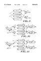
- FIG. 5 shows an exemplary functional block diagram of a digital quadrature sampling system in accordance with the present invention
- FIG. 6 shows an alternative exemplary functional block diagram of a digital quadrature sampling system in accordance with the present invention
- FIGS. 7A-7G show frequency domain graphs of the BQS process
- FIG. 8 shows enlarged versions of the output shown in FIG. 7G with the effect of BQS filter superimposed
- FIG. 9 shows an exemplary functional block diagram of a complex FIR filter
- FIG. 10 shows an exemplary functional block diagram of a hybrid BQS/EQ system in accordance with the present invention
- FIG. 11 shows an alternative exemplary functional block diagram of a hybrid BQS/EQ system in accordance with the present invention
- FIG. 12 shows another alternative exemplary functional block diagram of a hybrid BQS/EQ system in accordance with the present invention.
- FIG. 13 shows yet another alternative exemplary functional block diagram of a hybrid BQS/EQ system in accordance with the present invention.
- FIG. 2 there is shown an exemplary architecture of an adaptive radar system 20 which represents one example of system application for the present invention.
- the RF signal received by the antenna 21 is converted to IF signal by the receiver 22.
- the IF signal is converted by A/D converter 23, and then passed to a baseband quadrature sampler (BQS) module 24 which digitally generates in-phase (I) and quadrature (Q) parts from the A/D output.
- BQS baseband quadrature sampler
- the I/Q pair is then channel equalized by channel equalizer 25, pulse compressed at pulse compressor 26, and provided to an adaptive processor such as space time adaptive processor (STAP processor) 27.
- STAP processor space time adaptive processor
- FIG. 3 shows an exemplary functional block diagram of a digital BQS in accordance with the present invention.
- the quadrature sampler 30 has one A/D converter and digital mixers 32, 33.
- the lowpass filtering is carried out digitally as well with finite impulse response (FIR) filters 34, 35.
- FIR finite impulse response
- the digital N-tap FIR lowpass filters 34, 35 reject the signal beyond ⁇ c /2 in order to eliminate the negative frequency sideband and the DC component.
- the filter output is decimated by a factor of 4 by decimation circuits 36, 37 to produce the digital baseband signal (Nyquist output).
- the quadrature sampler 10 in FIG. 1 requires that the inphase and quadrature channels be closely matched.
- the quadrature sampler 30 utilizing one A/D and digital mixing as in FIG. 3 eliminates the channel matching requirement.
- the disadvantage of the quadrature sampler in FIG. 3 is that it requires the A/D to run at four times the rate of the device shown in FIG. 1. However, as high speed A/D's are now readily available, this is becoming less significant.
- a quadrature sampling system 40 can be configured as shown in FIG. 4 for simplification.
- the system 40 includes A/D converter 41, a processor controlled switch 42, FIR filters 43, 44, and decimation circuits 45, 46.
- the h(n) is the original N-tap filter coefficients, and h I (n) and h Q (n) are N/2 tap filter coefficients related to h(n) by, for example:
- I(2n) and Q(2n) can be rewritten as ##EQU1## where x I (n) and X Q (n) are the inputs to the filters h I (n) and h Q (n) respectively.
- the output of the A/D converter will be referred to as x(n).
- each of I(2n) and Q(2n) is equivalent to the sum of two FIR filter outputs whose throughput is half the rate.
- the inputs are alternately routed to the four filters whose coefficients are
- the input x(n) from A/D converter 51 is alternately directed by processor controlled switch 52 to four different filters 53-56 as shown in FIG. 5.
- the two (N/2)-tap filters of FIG. 3 running at 2 ⁇ c Hz are now replaced by four (N/4)-tap filters running 1/4 as fast, or at ⁇ c Hz.
- the total number of taps do not change from FIG. 4 to FIG. 5, but the filter throughput requirement decreases by a factor of two.
- N is a multiple of 4. That makes all the filters in FIG. 5 symmetrical and easy to design. If N is not a factor of 4, h(n) can be padded with zero's to make it a multiple of 4 in length. In addition, a system using 2K number of (N/2K)-tap filters can easily be configured.
- the cos and sin functions in FIG. 3 can have arbitrary initial phase. In a more general form, these functions would be written as cos(2 ⁇ c t+ ⁇ ) and sin(2 ⁇ c t+ ⁇ ), where ⁇ is the initial phase value. There are four possible values of ⁇ that allow the cos and sin functions to be 1, 0, and -1. These initial values are 0, ⁇ /2, ⁇ , and 3 ⁇ /2. Accordingly, this will set the stage for the possible sets of coefficients for the filters of FIG. 5.
- the quadrature sampling system 50 of FIG. 5 accepts discrete sets of four input samples at a time and produces the corresponding output sample.
- An output sample consists of an I value and a Q value. It is important to ensure which four input samples are processed to produce an output sample. This is due to the fact that the additions by summation circuits 57, 58 in FIG. 5 have to be performed on correct filter outputs. The corresponding filter outputs are added to produce an output sample.
- the four input samples, that are being processed to produce one output sample should go to the filters in a predetermined order.
- Choosing which sample is the first of four input samples is equivalent to choosing which output values are kept after decimation in the scheme of FIG. 3.
- the next input can be the second sample and so on. Therefore, the mapping of the input x(n) to the filters shown in FIG. 5 is only one of several possible mappings.
- the critical advantage of the quadrature sampler 50 of FIG. 5 over the sampler 40 shown in FIG. 4 is that the sampler 50 has approximately half the computational requirement. Although the number of total taps used in FIR filters is the same, the proposed filter has half the throughput requirement on the filters.
- the reduced computational requirement can reduce the size, weight, power, and cost approximately by a factor of two while keeping the sampler size, weight, power, and cost requirement about the same as the conventional sampler.
- FIG. 6 shows an exemplary generalized embodiment of a quadrature sampling system 60 with a decimation factor of 2K in accordance with the present invention.
- Each filter bank 63, 64 includes K filters 63a-63c, 64a-64c with N/2K taps.
- the input x(n) from A/D 61 is alternatively routed by processor controlled switch 62 so that all 2K filters receive one input of the 2K consecutive input samples.
- the input x(n) is also routed so that the input sample alternates between the I set of K filters 63 and the Q set of filters 64.
- the computational savings over that of FIG. 3 is equal to a factor of 4K, while the computational savings over that of FIG. 4 is equal to a factor of K.
- a very useful feature of the proposed quadrature sampler is that its computations are done mostly in FIR filters.
- the FIR filter computation can be very efficiently implemented in VLSI structures. It is also possible to implement FIR filter using Discrete Fourier Transform (DFT) or Fast Fourier Transform (FFT).
- DFT Discrete Fourier Transform
- FFT Fast Fourier Transform
- the quadrature sampler can be implemented mostly in software. Even in software implementation, the proposed quadrature sampler reduces the computation requirement by 50% over the conventional samplers.
- FIGS. 7A-7G show the frequency domain illustration of the BQS process.
- FIG. 7A shows the frequency spectrum at the input of the A/D converter.
- FIG. 7B shows the frequency response of an analog anti-aliasing filter (not shown) which is coupled at the front end of the A/D converter.
- the exemplary 4:1 down-sampling BQS scheme has the advantage that the analog anti-aliasing filter does not require very sharp transition bands.
- the lenient transition band requirement makes it easier for the analog anti-aliasing filter to be very flat and well behaved in the passband and to also have the high stopband rejection.
- the well behaved filter response is easier to equalize, and the high stopband rejection increases the signal to noise ratio.
- the filter's passband can be extended slightly beyond the signal band to provide some safety margin to make sure that the filter response is well behaved at the signal band edges.
- FIG. 7C shows the frequency spectrum at the output of the A/D converter.
- FIG. 7D is the frequency spectrum after the digital baseband conversion.
- FIG. 7E shows the frequency response of the BQS filter.
- FIG. 7F shows the frequency spectrum after BQS filtering, and
- FIG. 7G shows the frequency spectrum after decimation by 4:1.
- FIG. 8 shows enlarged versions of the output shown in FIG. 7G with the effect of BQS filter superimposed.
- the filter shape is plotted in dotted lines. Because the BQS filter is implemented digitally, the filter responses are identically matched in all the channels.
- the filter gain should be sufficiently low at the ends of the transition bands. It will be appreciated that the transition band is from the passband edge to the passband edge, and not from the passband edge to Nyquist frequency of ⁇ c /2. This is due to interest only in preventing aliasing into the passband.
- the number of taps needed for the lowpass BQS FIR filter depends on the requirements on passband ripple, stopband rejection, and transition width. Generally, low passband ripple, high stopband rejection, and low transition width are desired. Also desired is low passband signal loss, which depends on the passband shape.
- low passband ripple is generally desired in a BQS filter, it is usually not the limiting factor in, for example, applications involving radar performance.
- the passband ripples are exactly matched in all the channels because the BQS filters are implemented digitally. Therefore, the passband ripple does not effect the cancellation ratio.
- very large passband ripple will result in signal distortion. A reasonable practice is to keep the passband ripple below a few tenths of a dB.
- stopband rejection is more critical to the BQS filter operation. Insufficient stopband rejection causes aliasing. However, very high stopband rejection requires too many taps on the filter. How much stopband rejection is required depends very heavily on the system specifications.
- the low transition width results in low I/Q output sampling rate. Reduced data rate reduces computational requirement in subsequent processing tasks such as channel equalization, pulse compression, adaptive nulling, etc.
- the lower transition width also results in lower A/D sampling rate, since the A/D sampling rate is equal to four times the I/Q sampling rate.
- making transition width very small requires many filter taps, and one has to make tradeoffs between transition width and hardware complexity.
- the passband edge can be defined as the 3dB point of the filter instead of having all of the passband within the passband ripple.
- the filter design has to make proper tradeoffs between passband ripple, stopband rejection, transition width, passband signal loss, and hardware complexity.
- FIG. 9 shows an exemplary complex FIR filter 100 which is implemented using four FIRs 101-104 with their outputs combined with summation circuits 105, 106 as shown in FIG. 8.
- Two of the integer filters 101, 102 contain the in-phase part of coefficients and the other two filters 103,104 contain the quadrature coefficients.
- the channel equalization filter equalizes channel responses of the receiver and an A/D converter.
- a test signal is injected at the front of the receiver and the A/D output data is used to compute the equalization coefficients.
- the equalization filter equalizes everything in the injection path including filters, circulators, amplifiers, connectors, cables, A/D, etc.
- the anti-aliasing filter normally has relatively sharp frequency cutoff characteristics. In the process of achieving sharp cutoff characteristics, the anti-aliasing filter can end up with a significant channel mismatch. Other components generally have relatively flat frequency response around the passband and do not cause as significant mismatches. Therefore, how many taps are needed for channel equalization depends on what kind of analog filter is used as the anti-aliasing filter.
- FIG. 10 The functional block diagram of an exemplary hybrid BQS/EQ system 110 is shown in FIG. 10.
- the input IF signal which is centered around (2N+1)/4 of the A/D sampling rate, is sampled by an A/D converter 111.
- the sampled data is then digitally mixed to produce the baseband in-phase and quadrature components by respective digital mixers 112, 113.
- the I/Q signals are then N-tap complex FIR filtered with FIRs 114a, 114b, 115a, 115b to eliminate the negative frequency sideband and the DC component as well as to equalize the passband response.
- the filter outputs are then decimated by a factor of 4 by decimation circuits 118, 119 to produce the equalized digital baseband signal.
- the system 120 includes an A/D converter 121, a processor controlled switch 122 for switching odd and even values between the FIR filters 123a, 123b, 124a, 124b, summation circuits 125, 126, and decimation circuits 127, 128.
- the h I (n) and h Q (n) are the original N-tap filter coefficients.
- the h Ia (n) h Ib (n) h Qa (n) and h Qb (n) are the N/2 tap filter coefficients related to h I (n) and h Q (n) by, for example:
- the four N-tap filters in FIG. 10 are now replaced by eight (N/4)-tap filters running 1/4 as fast.
- the outputs of the filters are alternately applied to summation circuits 137, 138 to produce the I and Q components.
- n mod4 2
- n mod4 0
- the lower filter bank alternates such that the outputs from the FIRs with the I coefficient are applied to the Q summation circuit, and the negative value of the outputs from the filters with the Q coefficient are applied to the I summation circuit. It will be appreciated by those skilled in the art that other switching schemes are possible.
- FIG. 13 shows another alternative embodiment of an exemplary generalized hybrid BQS/EQ system 140 with a decimation factor of 2K in accordance with the present invention.
- Each filter bank 143, 144 includes K I filters 143a-c, 144a-c and K Q filters 143d-f, 144d-f, each with N/2K taps.
- the input x(n) from A/D 141 is alternatively routed by processor controlled switch 142 so that all 4K filters receive one input of the 2K consecutive input samples.
- the input x(n) is also routed so that two of the filters receive identical input, and so that the input sample alternates between the upper bank of K filters 143 and the lower bank of filters 144.
- the computational savings over that of FIG. 10 is equal to a factor of 4K, while the computational savings over that of FIG. 11 is equal to a factor of K.
Landscapes
- Engineering & Computer Science (AREA)
- Power Engineering (AREA)
- Digital Transmission Methods That Use Modulated Carrier Waves (AREA)
Abstract
A quadrature sampling system and method (BQS) and a hybrid quadrature sampling and channel equalization system and method (BQS/EQ) which convert input signals to baseband inphase and quadrature signal components. The BQS system includes an inphase signal channel including a first set of K filters, and a signal summer which sums the outputs of the first set of K filters to produce the inphase signal component; a quadrature signal channel including a second set of K filters, and a signal summer which sums the outputs of the second set of K filters to produce the quadrature signal component; and a controlled switch which provides input samples to the inphase and quadrature signal channels so that each filter of both channels receives one input sample of each sequence. The BQS/EQ system includes first and second sets of signal processing filter pairs, each pair including an inphase and a quadrature filter. A controlled switch alternately switches input samples between the first and second sets of signal processing filter pairs and applies selected ones of the input samples to each filter pair so that each filter pair receives one input sample of each sequence. The outputs of the filters pairs of each set are selectively provided to the inphase and quadrature signal summers.
Description
This invention was made with government support under Contract No. F19628-90-C-0002 awarded by the Air Force. The government has certain rights in the invention.
This is a continuation of application Ser. No. 08/320,164 filed on Oct. 7, 1994 now abandoned.
In many coherent sonar, radar, and communication applications, it is useful for the receiver outputs to be converted to baseband inphase and quadrature (denoted by I and Q) signal components. This process is referred to as quadrature sampling. When the application uses Digital Signal Processing (DSP), the I and Q signals are converted to digital signals by analog to digital (A/D) converters.
FIG. 1 shows a conventional analog quadrature sampler 10. The intermediate frequency (IF) input centered around the carrier frequency ƒc is mixed down to baseband via mixers 11, 12 by cos2πƒc t and sin2πƒc t local oscillator signals. The results are lowpass filtered by filters 13, 14 to eliminate the image signal generated while mixing, and then are passed to A/ D converters 15, 16 to produce digital baseband I and Q signals.
It is an object of the present invention to provide a digital baseband quadrature sampling (BQS) system, which is configured with finite impulse response (FIR) filters.
It is another object of the present invention to provide efficient BQS module architecture, which has half the computational requirement of the conventional architectures.
It is yet another object of the present invention to provide a new hybrid filter architecture, which combines the BQS and EQ filter into one hybrid filter, and which is far more efficient than the conventional hybrid filter architectures.
According to one embodiment of the present invention there is provided a quadrature sampling system and method which converts input signals to baseband inphase and quadrature signal components. The system includes circuitry which receives the input signal having a frequency centered around a predetermined carrier frequency. A signal processor such as an analog to digital converter continuously samples the input signal at a carrier frequency which is centered around a selected ratio, for example (2N+1)/4, of the sampling rate to produce discrete sequences of 2K input samples. An inphase signal channel includes a first set of K filters each having respective filter coefficients, and a signal summer which sums the outputs of the first set of K filters to produce the inphase signal component. A quadrature signal channel includes a second set of K filters each having respective filter coefficients, and a signal summer which sums the outputs of the second set of K filters to produce the quadrature signal component. The input samples are provided to the inphase and quadrature signal channels so that each filter of both channels receives one input sample of each sequence.
According to another embodiment of the present invention there is provided a hybrid quadrature sampling and channel equalization system and method which converts input signals to equalized baseband inphase and quadrature signal components. The system includes circuitry which receives the input signal having a frequency centered around a predetermined carrier frequency. A signal processor such as an analog to digital converter continuously samples the input signal at a carrier frequency which is centered around a selected ration, for instance (2N+1)/4, of the sampling rate to produce discrete sequences of 2K digital input samples. There is provided first and second sets of signal processing filter pairs each including an inphase filter having an inphase filter coefficient and a quadrature filter having a quadrature filter coefficient. The input samples are alternately switched between the first and second sets of signal processing filter pairs and selected ones of the input samples are applied to each filter pair so that each filter pair receives one digital input sample of each sequence. An inphase signal summer is operable for summing the outputs of selected filters from each of the signal processing filter sets to produce the inphase signal component. A quadrature signal summer is operable for summing the outputs of selected filters from each of the signal processing filter sets to produce the inphase signal component. The outputs of the filters pairs of each set are selectively provided to the inphase and quadrature signal summers.
FIG. 1 shows a block diagram of a conventional quadrature sampler;
FIG. 2 shows a block diagram of an exemplary adaptive radar system;
FIG. 3 shows an exemplary functional block diagram of a digital quadrature sampling system;
FIG. 4 shows an alternative exemplary functional block diagram of a digital quadrature sampling system;
FIG. 5 shows an exemplary functional block diagram of a digital quadrature sampling system in accordance with the present invention;
FIG. 6 shows an alternative exemplary functional block diagram of a digital quadrature sampling system in accordance with the present invention;
FIGS. 7A-7G show frequency domain graphs of the BQS process;
FIG. 8 shows enlarged versions of the output shown in FIG. 7G with the effect of BQS filter superimposed;
FIG. 9 shows an exemplary functional block diagram of a complex FIR filter;
FIG. 10 shows an exemplary functional block diagram of a hybrid BQS/EQ system in accordance with the present invention;
FIG. 11 shows an alternative exemplary functional block diagram of a hybrid BQS/EQ system in accordance with the present invention;
FIG. 12 shows another alternative exemplary functional block diagram of a hybrid BQS/EQ system in accordance with the present invention; and
FIG. 13 shows yet another alternative exemplary functional block diagram of a hybrid BQS/EQ system in accordance with the present invention.
With reference now to FIG. 2, there is shown an exemplary architecture of an adaptive radar system 20 which represents one example of system application for the present invention. The RF signal received by the antenna 21 is converted to IF signal by the receiver 22. The IF signal is converted by A/D converter 23, and then passed to a baseband quadrature sampler (BQS) module 24 which digitally generates in-phase (I) and quadrature (Q) parts from the A/D output. The I/Q pair is then channel equalized by channel equalizer 25, pulse compressed at pulse compressor 26, and provided to an adaptive processor such as space time adaptive processor (STAP processor) 27.
There are numerous alternative approaches for implementing the quadrature sampling technique. FIG. 3 shows an exemplary functional block diagram of a digital BQS in accordance with the present invention. The quadrature sampler 30 has one A/D converter and digital mixers 32, 33. The lowpass filtering is carried out digitally as well with finite impulse response (FIR) filters 34, 35. Assuming the A/D sampling rate ƒs is equal to 4/(2N+1)ƒc, i.e., the input IF signal is centered around (2N+1)/4 of the A/D sampling rate, then digital 1, 0 and -1 values can be used for the local oscillator signals cos2πƒc t and sin2πƒc t. This configuration greatly simplifies the digital mixing operations to produce the baseband in-phase (I) and quadrature (Q) components. The digital N-tap FIR lowpass filters 34, 35 reject the signal beyond ±ƒc /2 in order to eliminate the negative frequency sideband and the DC component. The filter output is decimated by a factor of 4 by decimation circuits 36, 37 to produce the digital baseband signal (Nyquist output).
The quadrature sampler 10 in FIG. 1 requires that the inphase and quadrature channels be closely matched. The quadrature sampler 30 utilizing one A/D and digital mixing as in FIG. 3 eliminates the channel matching requirement. The disadvantage of the quadrature sampler in FIG. 3 is that it requires the A/D to run at four times the rate of the device shown in FIG. 1. However, as high speed A/D's are now readily available, this is becoming less significant.
When 1, 0 and -1 values are to be used for the mixing signals cos2πƒc t and sin2πƒc t in FIG. 3, half of the filter inputs are zeros. Accordingly, a quadrature sampling system 40 can be configured as shown in FIG. 4 for simplification. The system 40 includes A/D converter 41, a processor controlled switch 42, FIR filters 43, 44, and decimation circuits 45, 46. The h(n) is the original N-tap filter coefficients, and hI (n) and hQ (n) are N/2 tap filter coefficients related to h(n) by, for example:
h.sub.I (n)=(-1).sup.n+1 h(2n+1)
h.sub.Q (n)=(-1).sup.n+1 h(2n)n=0,1 . . . ,(N/2)-1
It will be appreciated that since hI (n) and hQ (n) are followed by a decimation by a factor of two, half the filter outputs are discarded. The even numbered samples are switched to go to the hI (n) filter and the odd numbered samples go to the hQ (n) filter. The "odd" and "even" can be reversed in FIG. 4, and the system operates just as well. This quadrature sampling technique has half the computational requirement as the scheme shown in FIG. 3.
FIG. 5 shows an exemplary embodiment of a quadrature sampling system 50 in accordance with the present invention which reduces the digital computation requirement by a factor of two compared to the scheme in FIG. 4. Since hI (n) and hQ (n) filters of FIG. 4 are followed by the decimation by a factor of two, 50% of the filter outputs are discarded. Assume now that only the even numbered points form the outputs I(n) and Q(n) are used. That means I(2n) and Q(2n) need to be computed but I(2n+1) and Q(2n+1) don't need to be computed, where n=0,1,2, . . . ,(N/4)-1. The I(2n) and Q(2n) can be rewritten as ##EQU1## where xI (n) and XQ (n) are the inputs to the filters hI (n) and hQ (n) respectively. The output of the A/D converter will be referred to as x(n). Notice that each of I(2n) and Q(2n) is equivalent to the sum of two FIR filter outputs whose throughput is half the rate. Using a polyphase filtering technique, further optimization can be made to result in the system as shown in FIG. 4. The inputs are alternately routed to the four filters whose coefficients are
h.sub.Ia (n)=h.sub.I (2n+1)
h.sub.Ib (n)=h.sub.I (2n)n=0,1, . . . (N/4)-1
and
h.sub.Qa (n)=h.sub.Q (2n+1)
h.sub.Qb (n)=h.sub.Q (2n)n=0,1, . . . (N/4)-1
Accordingly, the input x(n) from A/D converter 51 is alternately directed by processor controlled switch 52 to four different filters 53-56 as shown in FIG. 5. The two (N/2)-tap filters of FIG. 3 running at 2ƒc Hz are now replaced by four (N/4)-tap filters running 1/4 as fast, or at ƒc Hz. The total number of taps do not change from FIG. 4 to FIG. 5, but the filter throughput requirement decreases by a factor of two.
It will be appreciated that in the illustrated exemplary embodiment of FIG. 5, N is a multiple of 4. That makes all the filters in FIG. 5 symmetrical and easy to design. If N is not a factor of 4, h(n) can be padded with zero's to make it a multiple of 4 in length. In addition, a system using 2K number of (N/2K)-tap filters can easily be configured.
The cos and sin functions in FIG. 3 can have arbitrary initial phase. In a more general form, these functions would be written as cos(2πƒc t+φ) and sin(2πƒc t+φ), where φ is the initial phase value. There are four possible values of φ that allow the cos and sin functions to be 1, 0, and -1. These initial values are 0, π/2, π, and 3π/2. Accordingly, this will set the stage for the possible sets of coefficients for the filters of FIG. 5.
The quadrature sampling system 50 of FIG. 5 accepts discrete sets of four input samples at a time and produces the corresponding output sample. An output sample consists of an I value and a Q value. It is important to ensure which four input samples are processed to produce an output sample. This is due to the fact that the additions by summation circuits 57, 58 in FIG. 5 have to be performed on correct filter outputs. The corresponding filter outputs are added to produce an output sample.
Once the set of filter coefficients are chosen, the four input samples, that are being processed to produce one output sample, should go to the filters in a predetermined order. There are various ways to group the input x(n) into sets for the four samples mentioned above. For example, in the input grouping, the first sample can be n(mod4)=0, n(mod4)=1, n(mod4)=2, or n(mod4)=3. Choosing which sample is the first of four input samples is equivalent to choosing which output values are kept after decimation in the scheme of FIG. 3. Once the first of four samples is chosen, the next input can be the second sample and so on. Therefore, the mapping of the input x(n) to the filters shown in FIG. 5 is only one of several possible mappings.
The critical advantage of the quadrature sampler 50 of FIG. 5 over the sampler 40 shown in FIG. 4 is that the sampler 50 has approximately half the computational requirement. Although the number of total taps used in FIR filters is the same, the proposed filter has half the throughput requirement on the filters. The reduced computational requirement can reduce the size, weight, power, and cost approximately by a factor of two while keeping the sampler size, weight, power, and cost requirement about the same as the conventional sampler.
FIG. 6 shows an exemplary generalized embodiment of a quadrature sampling system 60 with a decimation factor of 2K in accordance with the present invention. Each filter bank 63, 64 includes K filters 63a-63c, 64a-64c with N/2K taps. The input x(n) from A/D 61 is alternatively routed by processor controlled switch 62 so that all 2K filters receive one input of the 2K consecutive input samples. The input x(n) is also routed so that the input sample alternates between the I set of K filters 63 and the Q set of filters 64. The computational savings over that of FIG. 3 is equal to a factor of 4K, while the computational savings over that of FIG. 4 is equal to a factor of K.
A very useful feature of the proposed quadrature sampler is that its computations are done mostly in FIR filters. The FIR filter computation can be very efficiently implemented in VLSI structures. It is also possible to implement FIR filter using Discrete Fourier Transform (DFT) or Fast Fourier Transform (FFT).
In some applications involving relatively low data rates, the quadrature sampler can be implemented mostly in software. Even in software implementation, the proposed quadrature sampler reduces the computation requirement by 50% over the conventional samplers.
Now for illustrative purposes and assuming a radar application where ƒs =4ƒc, the following description pertains to the operation of the BQS of FIG. 3. FIGS. 7A-7G show the frequency domain illustration of the BQS process. FIG. 7A shows the frequency spectrum at the input of the A/D converter. FIG. 7B shows the frequency response of an analog anti-aliasing filter (not shown) which is coupled at the front end of the A/D converter. The exemplary 4:1 down-sampling BQS scheme has the advantage that the analog anti-aliasing filter does not require very sharp transition bands. The lenient transition band requirement makes it easier for the analog anti-aliasing filter to be very flat and well behaved in the passband and to also have the high stopband rejection. The well behaved filter response is easier to equalize, and the high stopband rejection increases the signal to noise ratio. The filter's passband can be extended slightly beyond the signal band to provide some safety margin to make sure that the filter response is well behaved at the signal band edges.
FIG. 7C shows the frequency spectrum at the output of the A/D converter. FIG. 7D is the frequency spectrum after the digital baseband conversion. FIG. 7E shows the frequency response of the BQS filter. FIG. 7F shows the frequency spectrum after BQS filtering, and FIG. 7G shows the frequency spectrum after decimation by 4:1.
FIG. 8 shows enlarged versions of the output shown in FIG. 7G with the effect of BQS filter superimposed. The filter shape is plotted in dotted lines. Because the BQS filter is implemented digitally, the filter responses are identically matched in all the channels. In order to prevent aliasing into the passband, the filter gain should be sufficiently low at the ends of the transition bands. It will be appreciated that the transition band is from the passband edge to the passband edge, and not from the passband edge to Nyquist frequency of ƒc /2. This is due to interest only in preventing aliasing into the passband.
The number of taps needed for the lowpass BQS FIR filter depends on the requirements on passband ripple, stopband rejection, and transition width. Generally, low passband ripple, high stopband rejection, and low transition width are desired. Also desired is low passband signal loss, which depends on the passband shape.
Although low passband ripple is generally desired in a BQS filter, it is usually not the limiting factor in, for example, applications involving radar performance. The passband ripples are exactly matched in all the channels because the BQS filters are implemented digitally. Therefore, the passband ripple does not effect the cancellation ratio. However, very large passband ripple will result in signal distortion. A reasonable practice is to keep the passband ripple below a few tenths of a dB.
The stopband rejection is more critical to the BQS filter operation. Insufficient stopband rejection causes aliasing. However, very high stopband rejection requires too many taps on the filter. How much stopband rejection is required depends very heavily on the system specifications.
The low transition width results in low I/Q output sampling rate. Reduced data rate reduces computational requirement in subsequent processing tasks such as channel equalization, pulse compression, adaptive nulling, etc. The lower transition width also results in lower A/D sampling rate, since the A/D sampling rate is equal to four times the I/Q sampling rate. However, making transition width very small requires many filter taps, and one has to make tradeoffs between transition width and hardware complexity.
One can also reduce the number of filter taps without increasing I/Q sampling rate by accepting some passband signal loss. For example, the passband edge can be defined as the 3dB point of the filter instead of having all of the passband within the passband ripple. In general, the filter design has to make proper tradeoffs between passband ripple, stopband rejection, transition width, passband signal loss, and hardware complexity.
The channel equalization (EQ) of the I and Q components requires a complex FIR filter configuration with programmable coefficients. FIG. 9 shows an exemplary complex FIR filter 100 which is implemented using four FIRs 101-104 with their outputs combined with summation circuits 105, 106 as shown in FIG. 8. Two of the integer filters 101, 102 contain the in-phase part of coefficients and the other two filters 103,104 contain the quadrature coefficients.
For example, in conventional UHF radar applications, the channel equalization filter equalizes channel responses of the receiver and an A/D converter. A test signal is injected at the front of the receiver and the A/D output data is used to compute the equalization coefficients. The equalization filter equalizes everything in the injection path including filters, circulators, amplifiers, connectors, cables, A/D, etc.
Normally, the most critical element to be equalized is the anti-aliasing filter. The reason being that the anti-aliasing filter has relatively sharp frequency cutoff characteristics. In the process of achieving sharp cutoff characteristics, the anti-aliasing filter can end up with a significant channel mismatch. Other components generally have relatively flat frequency response around the passband and do not cause as significant mismatches. Therefore, how many taps are needed for channel equalization depends on what kind of analog filter is used as the anti-aliasing filter.
It is possible to combine BQS and EQ filters into one hybrid complex FIR filter. Accordingly, an efficient hybrid filter architecture, which reduces the computational requirement by several fold, is described hereinafter. The functional block diagram of an exemplary hybrid BQS/EQ system 110 is shown in FIG. 10. The input IF signal, which is centered around (2N+1)/4 of the A/D sampling rate, is sampled by an A/D converter 111. The sampled data is then digitally mixed to produce the baseband in-phase and quadrature components by respective digital mixers 112, 113. The I/Q signals are then N-tap complex FIR filtered with FIRs 114a, 114b, 115a, 115b to eliminate the negative frequency sideband and the DC component as well as to equalize the passband response. The filter outputs are then decimated by a factor of 4 by decimation circuits 118, 119 to produce the equalized digital baseband signal.
Four N-tap FIR filters are used to implement one N-tap complex FIR filter.
Since half the filter inputs in FIG. 10 are zeroes, a simplification of the system is shown by exemplary system 120 in FIG. 11. The system 120 includes an A/D converter 121, a processor controlled switch 122 for switching odd and even values between the FIR filters 123a, 123b, 124a, 124b, summation circuits 125, 126, and decimation circuits 127, 128. The hI (n) and hQ (n) are the original N-tap filter coefficients. The hIa (n) hIb (n) hQa (n) and hQb (n) are the N/2 tap filter coefficients related to hI (n) and hQ (n) by, for example:
h.sub.Ia (n)=(-1).sup.n+1 h.sub.I (2n+1)
h.sub.Ib (n)=(-1).sup.n+1 h.sub.I (2n)
h.sub.Qa (n)=(-1).sup.n+1 h.sub.Q (2n+1)
h.sub.Qb (n)=(-1).sup.n+1 h.sub.Q (2n)n=0,1, . . . ,(N/2)-1
At this point, it will be appreciated that since hI (n) and hQ (n) are followed by a decimation by a factor of two, half of the filter outputs are discarded. Using a polyphase filtering technique, further optimization can be made to configure an exemplary hybrid BQS/EQ system 130 in accordance with the present invention as is shown in FIG. 12. The discrete sets of inputs from A/D converter 131 are alternately routed by processor controlled switch 132 to the eight filters 133a-b, 134a-b, 135a-b, 136a-b, whose respective coefficients are, for example:
h.sub.Ia1 (n)=h.sub.Ia (2n)
h.sub.Ia2 (n)=h.sub.Ia (2n+1)
h.sub.Ib1 (n)=h.sub.Ib (2n)
h.sub.Ib2 (n)=h.sub.Ib (2n+1)
h.sub.Qa1 (n)=h.sub.Qa (2n)
h.sub.Qa2 (n)=h.sub.Qa (2n+1)
h.sub.Qa1 (n)=h.sub.Qb (2n)
h.sub.Qa2 (n)=h.sub.Qb (2n+1)n=0, 1, . . . ,(N/4)-1
The four N-tap filters in FIG. 10 are now replaced by eight (N/4)-tap filters running 1/4 as fast. The outputs of the filters are alternately applied to summation circuits 137, 138 to produce the I and Q components. For example, with consecutive mapping values n mod4=2, n mod4=0, n mod4=3, and n mod4=1, the output is switched such that the upper filter bank has the outputs from the FIRs with an I coefficient applied to the I summation circuit 137, and the outputs from the FIRs with a Q coefficient are applied to the Q summation circuit 138. The lower filter bank alternates such that the outputs from the FIRs with the I coefficient are applied to the Q summation circuit, and the negative value of the outputs from the filters with the Q coefficient are applied to the I summation circuit. It will be appreciated by those skilled in the art that other switching schemes are possible.
The total number of taps do not change from FIG. 11 to FIG. 12, but the filter throughput requirement decreases by a factor of two. Overall, the computational requirements required is reduced by a factor of eight from FIG. 10 to FIG. 12.
FIG. 13 shows another alternative embodiment of an exemplary generalized hybrid BQS/EQ system 140 with a decimation factor of 2K in accordance with the present invention. Each filter bank 143, 144 includes K I filters 143a-c, 144a-c and K Q filters 143d-f, 144d-f, each with N/2K taps. The input x(n) from A/D 141 is alternatively routed by processor controlled switch 142 so that all 4K filters receive one input of the 2K consecutive input samples. The input x(n) is also routed so that two of the filters receive identical input, and so that the input sample alternates between the upper bank of K filters 143 and the lower bank of filters 144. The computational savings over that of FIG. 10 is equal to a factor of 4K, while the computational savings over that of FIG. 11 is equal to a factor of K.
In comparing the efficiency of the separate BQS/EQ filters versus the efficiency of the hybrid filter in a case where k=2, a system with N BQS taps and M EQ taps will be considered. Most of the degrees of freedom in the BQS filter are used to reject the stopband. Therefore, the equivalent hybrid filter would need approximately N taps for stopband attenuation. For the EQ filter, most of the degrees of freedom can be made to equalize the passband by appropriate weighting. Therefore, the equivalent hybrid filter would need approximately M taps for passband equalization. Therefore, the equivalent hybrid filter would need N+M total taps. A system with N-tap BQS filter and M-tap EQ filter needs N+4M real taps running at the I/Q sampling rate. An equivalent hybrid filter with N+M complex taps needs 2(N+M) real taps running at the I/Q sampling rate. Therefore, if the BQS tap-count is much larger than the EQ tap-count, the separate filter approach is more efficient. However, if the EQ tap-count is much larger than the BQS tap-count, then the hybrid filter approach is more efficient. When the BQS filter tap-count is approximately twice the EQ filter tap-count (N=2M), the separate and hybrid approaches would be comparable.
However, the hybrid filter will probably perform slightly better than the separate filters when N=2M. This is because several degrees of freedom in the BQS filter were used on the passband even though most of the degrees of freedom were used in the stopband. These several degrees of freedom do not perform passband equalization or stopband rejection. Therefore, the hybrid filter may use these several extra degrees of freedom for additional stopband attenuation and/or passband equalization. Whether the hybrid filter actually performs better needs to be verified by experiments. In addition, computing the hybrid filter coefficients requires more computation than computing the EQ filter coefficients, since the EQ filter has much fewer taps.
The foregoing description has been set forth to illustrate the invention and is not intended to be limiting. Since modifications of the described embodiments incorporating the spirit and substance of the invention may occur to persons skilled in the art, the scope of the invention should be limited solely with reference to the appended claims and equivalents thereof.
Claims (13)
1. A quadrature sampling system which converts input signals to baseband inphase and quadrature signal components, said system comprising:
a signal receiver which receives said input signal having a frequency centered around a predetermined carrier frequency;
a signal processor which continuously samples said input signal at a ratio of said carrier frequency to produce discrete sequences of 2K input samples, where K is an integer;
an inphase signal channel including a first set of K filters each having respective filter coefficients, said first set of filters arranged to receive said discrete sequences, and a first signal summer which sums the outputs of said first set of K filters to produce said inphase signal component;
a quadrature signal channel including a second set of K filters each having respective filter coefficients, said second set of filters arranged to receive said discrete sequences, and a second signal summer which sums the outputs of said second set of K filters to produce said quadrature signal component; and
means for providing said input samples to said inphase and quadrature signal channels so that each filter of both channels receives one input sample of each sequence.
2. The system of claim 1, wherein said signal processor comprises an analog-to-digital converter which generates digital input samples.
3. The system of claim 1, wherein said signal processor continuously samples said input signal at a sampling frequency of 4/(2N+1) of said carrier frequency, where N is an integer.
4. The system of claim 1, wherein each of said filters comprises N/2K taps, where N is an integer.
5. The system of claim 1, wherein said providing means operates to alternately switch said input samples of each sequence between said inphase and quadrature signal channels.
6. A method of quadrature sampling by converting input signals to baseband inphase and quadrature signal components, said method comprising:
receiving said input signal having a frequency centered around a predetermined carrier frequency;
continuously sampling said input signal at a ratio of said carrier frequency and producing discrete sequences of 2K input samples, where K is an integer;
applying selected portions of said discrete sequences at an inphase signal channel including a first set of K filters each having respective filter coefficients, said first set of filters arranged to receive said discrete sequences;
summing the outputs of said first set of K filters to produce said inphase signal component;
applying selected portions of said discrete sequences to a quadrature signal channel including a second set of K filters each having respective filter coefficients, said second set of filters arranged to receive said discrete sequences;
summing the outputs of said second set of K filters to produce said quadrature signal component; and
alternately providing said input samples of each sequence between said inphase and quadrature signal channels and for applying alternate ones of the input samples to a selected one of said filters for each channel so that each filter receives one input sample of each sequence.
7. A hybrid quadrature sampling and channel equalization system which converts input signals to equalized baseband inphase and quadrature signal components, said system comprising:
a receiver which receives said input signal having a frequency centered around a predetermined carrier frequency;
a signal processor which continuously samples said input signal at a ratio of said carrier frequency to produce discrete sequences of 2K input samples, where K is an integer;
first and second sets of K signal processing filter pairs, each filter pair including an inphase filter having an inphase filter coefficient and a quadrature filter having a quadrature filter coefficient, said first and second set of filter pairs arranged to receive said discrete sequences;
means for alternately switching said input samples between said first and second sets of K signal processing filter pairs and for applying selected ones of the input samples to each filter pair so that each filter pair receives one input sample of each sequence;
an inphase signal summer which sums the outputs of selected filters from each of said signal processing filter pairs to produce said inphase signal component;
a quadrature signal summer which sums the outputs of selected filters from each of said signal processing filter sets to produce said inphase signal component; and
means for selectively providing the outputs of each of said filters of said first and second sets to said inphase and quadrature signal summers.
8. The system of claim 7, wherein said signal processor comprises an analog-to-digital converter which generates digital input samples.
9. The system of claim 7, wherein said signal processor continuously samples said input signal at a sampling frequency of 4/(2N+1) of said carrier frequency, where N is an integer.
10. The system of claim 7, wherein each of said filters comprises N/2K taps, where N is an integer.
11. The system of claim 7, wherein said selective providing means operates to provide the outputs of the inphase filters of said first filter pair set to said inphase signal summer and the outputs of quadrature filters of said first set to said quadrature signal summer.
12. The system of claim 11, wherein said selective providing means further operates to provide the negative value of the outputs of the inphase filters of said second filter pair set to said quadrature signal summer and the outputs of quadrature filters of said second set to said inphase signal summer.
13. A method of quadrature sampling and channel equalization for converting input signals to equalized baseband inphase and quadrature signal components, said method comprising:
receiving said input signal having a frequency centered around a predetermined carrier frequency;
continuously sampling said input signal at a ratio of said carrier frequency and producing discrete sequences of 2K input samples, where K is an integer;
alternately switching said input samples between first and second sets of K signal processing filter pairs, each filter pair including an inphase filter having an inphase filter coefficient and a quadrature filter having a quadrature filter coefficient, said first and second set of filters arranged to receive said discrete sequences;
applying selected ones of the input samples to each filter pair so that each filter pair receives one digital input sample of each sequence;
selectively providing the outputs of said filter pairs of said first and second sets to inphase and quadrature signal summers; and
summing the outputs of selected filters from each of said signal processing filter pairs to produce said inphase signal component, and summing the outputs of selected filters from each of said signal processing filter sets to produce said inphase signal component.
Priority Applications (1)
| Application Number | Priority Date | Filing Date | Title |
|---|---|---|---|
| US08/599,554 US5841811A (en) | 1994-10-07 | 1996-02-28 | Quadrature sampling system and hybrid equalizer |
Applications Claiming Priority (2)
| Application Number | Priority Date | Filing Date | Title |
|---|---|---|---|
| US32016494A | 1994-10-07 | 1994-10-07 | |
| US08/599,554 US5841811A (en) | 1994-10-07 | 1996-02-28 | Quadrature sampling system and hybrid equalizer |
Related Parent Applications (1)
| Application Number | Title | Priority Date | Filing Date |
|---|---|---|---|
| US32016494A Continuation | 1994-10-07 | 1994-10-07 |
Publications (1)
| Publication Number | Publication Date |
|---|---|
| US5841811A true US5841811A (en) | 1998-11-24 |
Family
ID=23245162
Family Applications (1)
| Application Number | Title | Priority Date | Filing Date |
|---|---|---|---|
| US08/599,554 Expired - Fee Related US5841811A (en) | 1994-10-07 | 1996-02-28 | Quadrature sampling system and hybrid equalizer |
Country Status (2)
| Country | Link |
|---|---|
| US (1) | US5841811A (en) |
| WO (1) | WO1996011527A1 (en) |
Cited By (47)
| Publication number | Priority date | Publication date | Assignee | Title |
|---|---|---|---|---|
| US5999575A (en) * | 1996-01-18 | 1999-12-07 | Daihen Corporation | Channel separating filter apparatus, PSK demodulator apparatus and PSK receiver apparatus each equipped with channel separating filter apparatus |
| US6049573A (en) * | 1997-12-11 | 2000-04-11 | Massachusetts Institute Of Technology | Efficient polyphase quadrature digital tuner |
| WO2001018954A1 (en) * | 1999-09-10 | 2001-03-15 | Raytheon Company | System for down-converting a signal using a discrete fourier-transform calculation and method |
| US6272174B1 (en) * | 1997-11-04 | 2001-08-07 | Rockwell Collins, Inc. | Multiple frequency bin processing |
| WO2000064042A3 (en) * | 1999-04-16 | 2001-10-25 | Parkervision Inc | Device for frequency down-converting using undersamling, and method |
| US6496134B1 (en) * | 1999-09-28 | 2002-12-17 | Ando Electric Co., Ltd. | Frequency spectrum method and frequency spectrum analyzer |
| US6542722B1 (en) | 1998-10-21 | 2003-04-01 | Parkervision, Inc. | Method and system for frequency up-conversion with variety of transmitter configurations |
| US6560301B1 (en) | 1998-10-21 | 2003-05-06 | Parkervision, Inc. | Integrated frequency translation and selectivity with a variety of filter embodiments |
| US6580902B1 (en) | 1998-10-21 | 2003-06-17 | Parkervision, Inc. | Frequency translation using optimized switch structures |
| US6647250B1 (en) | 1998-10-21 | 2003-11-11 | Parkervision, Inc. | Method and system for ensuring reception of a communications signal |
| US6650264B1 (en) | 1999-03-10 | 2003-11-18 | Cirrus Logic, Inc. | Quadrature sampling architecture and method for analog-to-digital converters |
| US6686830B1 (en) * | 2000-06-28 | 2004-02-03 | Applied Wireless Identifications Group | Homodyne I/Q transceiver for a spread spectrum reader |
| US6694128B1 (en) | 1998-08-18 | 2004-02-17 | Parkervision, Inc. | Frequency synthesizer using universal frequency translation technology |
| US6704549B1 (en) | 1999-03-03 | 2004-03-09 | Parkvision, Inc. | Multi-mode, multi-band communication system |
| US6704558B1 (en) | 1999-01-22 | 2004-03-09 | Parkervision, Inc. | Image-reject down-converter and embodiments thereof, such as the family radio service |
| US6721375B1 (en) * | 1998-11-23 | 2004-04-13 | Robert Bosch Gmbh | Method and device for compensating phase delays |
| US6768372B2 (en) * | 2002-12-20 | 2004-07-27 | Intel Corporation | Analog filter architecture |
| US6798351B1 (en) | 1998-10-21 | 2004-09-28 | Parkervision, Inc. | Automated meter reader applications of universal frequency translation |
| US6813485B2 (en) | 1998-10-21 | 2004-11-02 | Parkervision, Inc. | Method and system for down-converting and up-converting an electromagnetic signal, and transforms for same |
| US20060109941A1 (en) * | 2004-10-29 | 2006-05-25 | KEELE D B Jr | Log-sampled filter system |
| US20070035380A1 (en) * | 2004-11-18 | 2007-02-15 | Overhultz Gary L | Systems and methods for monitoring open stock merchandising |
| US20070071131A1 (en) * | 2004-11-18 | 2007-03-29 | Pyne John W | Switched phase receiver for a long range RFID system |
| EP1777811A1 (en) * | 2005-10-19 | 2007-04-25 | CSEM Centre Suisse d'Electronique et de Microtechnique SA | Device and method for the demodulation of modulated electric signals |
| US20080232511A1 (en) * | 2007-03-22 | 2008-09-25 | Infineon Technologies | Combined mixer and polyphase decimator |
| US7653145B2 (en) | 1999-08-04 | 2010-01-26 | Parkervision, Inc. | Wireless local area network (WLAN) using universal frequency translation technology including multi-phase embodiments and circuit implementations |
| US7653158B2 (en) | 2001-11-09 | 2010-01-26 | Parkervision, Inc. | Gain control in a communication channel |
| US7693230B2 (en) | 1999-04-16 | 2010-04-06 | Parkervision, Inc. | Apparatus and method of differential IQ frequency up-conversion |
| US7724845B2 (en) | 1999-04-16 | 2010-05-25 | Parkervision, Inc. | Method and system for down-converting and electromagnetic signal, and transforms for same |
| US7773688B2 (en) | 1999-04-16 | 2010-08-10 | Parkervision, Inc. | Method, system, and apparatus for balanced frequency up-conversion, including circuitry to directly couple the outputs of multiple transistors |
| US7822401B2 (en) | 2000-04-14 | 2010-10-26 | Parkervision, Inc. | Apparatus and method for down-converting electromagnetic signals by controlled charging and discharging of a capacitor |
| US7865177B2 (en) | 1998-10-21 | 2011-01-04 | Parkervision, Inc. | Method and system for down-converting an electromagnetic signal, and transforms for same, and aperture relationships |
| US7894789B2 (en) | 1999-04-16 | 2011-02-22 | Parkervision, Inc. | Down-conversion of an electromagnetic signal with feedback control |
| US7991815B2 (en) | 2000-11-14 | 2011-08-02 | Parkervision, Inc. | Methods, systems, and computer program products for parallel correlation and applications thereof |
| US8019291B2 (en) | 1998-10-21 | 2011-09-13 | Parkervision, Inc. | Method and system for frequency down-conversion and frequency up-conversion |
| US8160196B2 (en) | 2002-07-18 | 2012-04-17 | Parkervision, Inc. | Networking methods and systems |
| WO2012080795A1 (en) * | 2010-12-16 | 2012-06-21 | Telefonaktiebolaget Lm Ericsson (Publ) | Integrated demodulator, filter and decimator (dfd) for a radio receiver |
| US8233855B2 (en) | 1998-10-21 | 2012-07-31 | Parkervision, Inc. | Up-conversion based on gated information signal |
| US8295406B1 (en) | 1999-08-04 | 2012-10-23 | Parkervision, Inc. | Universal platform module for a plurality of communication protocols |
| US8407061B2 (en) | 2002-07-18 | 2013-03-26 | Parkervision, Inc. | Networking methods and systems |
| US8543074B1 (en) | 2012-04-17 | 2013-09-24 | Telefonaktiebolaget Lm Ericsson (Publ) | Frequency agile digital radio receiver |
| US8817854B2 (en) | 2012-10-12 | 2014-08-26 | Innoventure L.P. | Phase sector based RF signal decimation |
| US9225368B2 (en) | 2012-10-12 | 2015-12-29 | Innoventure L.P. | Periodic time segment sequence based signal generation |
| WO2016016409A1 (en) * | 2014-07-30 | 2016-02-04 | Thales | Digital frequency converter and method of processing in a digital frequency converter |
| US9264268B2 (en) | 2012-10-12 | 2016-02-16 | Innoventure L.P. | Periodic time segment sequence based decimation |
| US9484969B2 (en) | 2012-10-12 | 2016-11-01 | Innoventure L.P. | Delta-pi signal acquisition |
| US9484968B2 (en) | 2012-10-12 | 2016-11-01 | Innoventure L.P. | Post conversion mixing |
| US11885874B2 (en) * | 2018-12-19 | 2024-01-30 | Semiconductor Components Industries, Llc | Acoustic distance measuring circuit and method for low frequency modulated (LFM) chirp signals |
Families Citing this family (1)
| Publication number | Priority date | Publication date | Assignee | Title |
|---|---|---|---|---|
| JPH10313260A (en) * | 1997-05-13 | 1998-11-24 | Matsushita Electric Ind Co Ltd | Receiver |
Citations (11)
| Publication number | Priority date | Publication date | Assignee | Title |
|---|---|---|---|---|
| US4691176A (en) * | 1986-03-17 | 1987-09-01 | General Electric Company | Adaptive carrier tracking circuit |
| US4779054A (en) * | 1987-08-17 | 1988-10-18 | General Electric Company | Digital inphase/quadrature product detector |
| US4821294A (en) * | 1987-07-08 | 1989-04-11 | California Institute Of Technology | Digital signal processor and processing method for GPS receivers |
| US4910467A (en) * | 1988-11-02 | 1990-03-20 | Motorola, Inc. | Method and apparatus for decoding a quadrature modulated signal |
| US4922506A (en) * | 1988-01-11 | 1990-05-01 | Sicom Corporation | Compensating for distortion in a communication channel |
| US4975927A (en) * | 1988-11-10 | 1990-12-04 | Nec Corporation | Demodulator with composite transversal equalizer and eye detection clock synchronizer |
| EP0445335A1 (en) * | 1990-03-09 | 1991-09-11 | Deutsche ITT Industries GmbH | Device and method for increasing the clock rate of a fir filter |
| US5081521A (en) * | 1990-04-13 | 1992-01-14 | Faroudja Y C | NTSC color television system with improved chroma bandwidth and chroma ringing reduction |
| US5111202A (en) * | 1991-03-28 | 1992-05-05 | Itt Corporation | Extended dynamic range quadrature detector with parallel channel arrangement |
| US5200978A (en) * | 1990-05-18 | 1993-04-06 | Siemens Telecomunicazioni S.P.A | Process for actuation of multi-level digital modulation by a digital signal processor |
| US5298908A (en) * | 1987-11-27 | 1994-03-29 | Unisys Corporation | Interference nulling system for antennas |
-
1995
- 1995-09-26 WO PCT/US1995/012251 patent/WO1996011527A1/en active Application Filing
-
1996
- 1996-02-28 US US08/599,554 patent/US5841811A/en not_active Expired - Fee Related
Patent Citations (11)
| Publication number | Priority date | Publication date | Assignee | Title |
|---|---|---|---|---|
| US4691176A (en) * | 1986-03-17 | 1987-09-01 | General Electric Company | Adaptive carrier tracking circuit |
| US4821294A (en) * | 1987-07-08 | 1989-04-11 | California Institute Of Technology | Digital signal processor and processing method for GPS receivers |
| US4779054A (en) * | 1987-08-17 | 1988-10-18 | General Electric Company | Digital inphase/quadrature product detector |
| US5298908A (en) * | 1987-11-27 | 1994-03-29 | Unisys Corporation | Interference nulling system for antennas |
| US4922506A (en) * | 1988-01-11 | 1990-05-01 | Sicom Corporation | Compensating for distortion in a communication channel |
| US4910467A (en) * | 1988-11-02 | 1990-03-20 | Motorola, Inc. | Method and apparatus for decoding a quadrature modulated signal |
| US4975927A (en) * | 1988-11-10 | 1990-12-04 | Nec Corporation | Demodulator with composite transversal equalizer and eye detection clock synchronizer |
| EP0445335A1 (en) * | 1990-03-09 | 1991-09-11 | Deutsche ITT Industries GmbH | Device and method for increasing the clock rate of a fir filter |
| US5081521A (en) * | 1990-04-13 | 1992-01-14 | Faroudja Y C | NTSC color television system with improved chroma bandwidth and chroma ringing reduction |
| US5200978A (en) * | 1990-05-18 | 1993-04-06 | Siemens Telecomunicazioni S.P.A | Process for actuation of multi-level digital modulation by a digital signal processor |
| US5111202A (en) * | 1991-03-28 | 1992-05-05 | Itt Corporation | Extended dynamic range quadrature detector with parallel channel arrangement |
Non-Patent Citations (34)
| Title |
|---|
| Bellanger, Maurice G., Georges Bonnerot and Michel Coudreuse, "Digital Filtering by Polyphase Network: Application to Sample-Rate Alteration and Filter Banks", IEEE Transactions on Acoustics, Speech and Signal Processing, vol. ASSP-24, No. 2, Apr. 1976, pp. 109-114. |
| Bellanger, Maurice G., Georges Bonnerot and Michel Coudreuse, Digital Filtering by Polyphase Network: Application to Sample Rate Alteration and Filter Banks , IEEE Transactions on Acoustics, Speech and Signal Processing , vol. ASSP 24, No. 2, Apr. 1976, pp. 109 114. * |
| Brown, Jr., J.L., "On Quadrature Sampling of Bandpass Signals", IEEE Transactions on Aerospace and Electronic Systems, vol. AES-15, No. 3, May 1979, pp. 366-371. |
| Brown, Jr., J.L., On Quadrature Sampling of Bandpass Signals , IEEE Transactions on Aerospace and Electronic Systems , vol. AES 15, No. 3, May 1979, pp. 366 371. * |
| Considine, V., "Digital Complex Sampling", Electronics Letters, Aug. 4, 1983, vol. 19, No. 16, pp. 608-609. |
| Considine, V., Digital Complex Sampling , Electronics Letters , Aug. 4, 1983, vol. 19, No. 16, pp. 608 609. * |
| Grace, O.D., and S.P. Pitt, "Quadrature Sampling of High-Frequency Waveforms", The Journal of the Acoustical Society of America, vol. 44, No. 5, 1968, pp. 1453-1454. |
| Grace, O.D., and S.P. Pitt, Quadrature Sampling of High Frequency Waveforms , The Journal of the Acoustical Society of America , vol. 44, No. 5, 1968, pp. 1453 1454. * |
| Horiguchi, Toshio, "A Full Digital Phase Delay Compensation Beam-Forming Scheme for Ultrasonic Imaging Using Arrays", NEC Res. & Develop., No. 88, Jan. 1988, pp. 47-56. |
| Horiguchi, Toshio, A Full Digital Phase Delay Compensation Beam Forming Scheme for Ultrasonic Imaging Using Arrays , NEC Res. & Develop. , No. 88, Jan. 1988, pp. 47 56. * |
| Liu, Hulin, Arif Ghafoor and Peter H. Stockmann, "A New Quadrature Sampling and Processing Approach", IEEE Transactions on Aerospace and Electronic Systems, vol. 25, No. 5, Sep. 1989, pp. 733-748. |
| Liu, Hulin, Arif Ghafoor and Peter H. Stockmann, A New Quadrature Sampling and Processing Approach , IEEE Transactions on Aerospace and Electronic Systems , vol. 25, No. 5, Sep. 1989, pp. 733 748. * |
| Lu, Chung H., "Polyphase FIR Filters for the Demodulation of Chrominance Signals", IEEE ISCAS, 1988, pp. 2313-2316. |
| Lu, Chung H., Polyphase FIR Filters for the Demodulation of Chrominance Signals , IEEE ISCAS , 1988, pp. 2313 2316. * |
| Marino, Jos e B. and Enrique Masgrau, Sampling In Phase and Quadrature Components of Band Pass Signals , Signal Processing , vol. 20, No. 2, Jun. 1990, pp. 121 125 & cover page. * |
| Marino, Jose B. and Enrique Masgrau, "Sampling In-Phase and Quadrature Components of Band-Pass Signals", Signal Processing, vol. 20, No. 2, Jun. 1990, pp. 121-125 & cover page. |
| Pellon, Leopold E., "A Double Nyquist Digital Product Detector for Quadrature Sampling", IEEE Transactions on Signal Processing, vol. 40, No. 7, Jul. 1992, pp. 1670-1681. |
| Pellon, Leopold E., A Double Nyquist Digital Product Detector for Quadrature Sampling , IEEE Transactions on Signal Processing , vol. 40, No. 7, Jul. 1992, pp. 1670 1681. * |
| Rader, Charles M., "A Simple Method for Sampling In-Phase and Quadrature Components", IEEE Transactions on Aerospace and Electronic Systems, vol. AES-20, No. 6, Nov. 1984, pp. 821-824. |
| Rader, Charles M., A Simple Method for Sampling In Phase and Quadrature Components , IEEE Transactions on Aerospace and Electronic Systems , vol. AES 20, No. 6, Nov. 1984, pp. 821 824. * |
| Rice, D.W. and K.H. Wu, "Quadrature Sampling With High Dynamic Range", IEEE Transactions on Aerospace and Electronic Systems, vol. AES-18, No. 4, Nov. 1982, pp. 736-739. |
| Rice, D.W. and K.H. Wu, Quadrature Sampling With High Dynamic Range , IEEE Transactions on Aerospace and Electronic Systems , vol. AES 18, No. 4, Nov. 1982, pp. 736 739. * |
| Sadr, Ramin and William J. Hurd, "Digital Carrier Demodulation for the DSN Advanced Receiver", TDA Progress Report, Jet Propulsion Lab. & NASA Case No. NPO-17628, Jan.-Mar. 1988, pp. 1a-16a, pp. i-ii, & table of contents pp. 1-2. |
| Sadr, Ramin and William J. Hurd, Digital Carrier Demodulation for the DSN Advanced Receiver , TDA Progress Report , Jet Propulsion Lab. & NASA Case No. NPO 17628, Jan. Mar. 1988, pp. 1a 16a, pp. i ii, & table of contents pp. 1 2. * |
| Saulnier, Gary J., Charles McD. Puckette, IV, Richard C. Gaus, Jr., Robert J. Dunki Jacobs and Timothy E. Thiel, A VLSI Demodulator for Digital RF Network Applications: Theory and Results , IEEE Journal on Selected Areas in Communications , vol. 8, No. 8, Oct. 1990, pp. 1500 1511. * |
| Saulnier, Gary J., Charles McD. Puckette, IV, Richard C. Gaus, Jr., Robert J. Dunki-Jacobs and Timothy E. Thiel, "A VLSI Demodulator for Digital RF Network Applications: Theory and Results", IEEE Journal on Selected Areas in Communications, vol. 8, No. 8, Oct. 1990, pp. 1500-1511. |
| Teitelbaum, Kenneth, "A Flexible Processor for a Digital Adaptive Array Radar", Proceedings of the 1991 IEEE National Radar Conference, Los Angeles, CA, Mar. 12-13, 1991, pp. 103-107, & Briefing on Group 49 Processor, cover & p. 2. |
| Teitelbaum, Kenneth, A Flexible Processor for a Digital Adaptive Array Radar , Proceedings of the 1991 IEEE National Radar Conference , Los Angeles, CA, Mar. 12 13, 1991, pp. 103 107, & Briefing on Group 49 Processor, cover & p. 2. * |
| Thomas, J.B., B. Rayhrer and L.E. Young, "Sampling Downconverter for Radio-Frequency Signals", NASA Jet Propulsion Laboratory Progress Report, JPL & NASA Case No. NPO-17530, pp. i, 1, 1a-16a. |
| Thomas, J.B., B. Rayhrer and L.E. Young, Sampling Downconverter for Radio Frequency Signals , NASA Jet Propulsion Laboratory Progress Report , JPL & NASA Case No. NPO 17530, pp. i, 1, 1a 16a. * |
| Waters, W.M. and B.R. Jarrett, "Bandpass Signal Sampling and Coherent Detection", IEEE Transactions on Aerospace and Electronic Systems, vol. AES-18, No. 4, Nov. 1982, pp. 731-736. |
| Waters, W.M. and B.R. Jarrett, Bandpass Signal Sampling and Coherent Detection , IEEE Transactions on Aerospace and Electronic Systems , vol. AES 18, No. 4, Nov. 1982, pp. 731 736. * |
| Webb, Richard C., "If Signal Sampling Improves Receiver Detection Accuracy", Microwaves & RF, Mar. 1989, pp. 99-103. |
| Webb, Richard C., If Signal Sampling Improves Receiver Detection Accuracy , Microwaves & RF , Mar. 1989, pp. 99 103. * |
Cited By (90)
| Publication number | Priority date | Publication date | Assignee | Title |
|---|---|---|---|---|
| US5999575A (en) * | 1996-01-18 | 1999-12-07 | Daihen Corporation | Channel separating filter apparatus, PSK demodulator apparatus and PSK receiver apparatus each equipped with channel separating filter apparatus |
| US6272174B1 (en) * | 1997-11-04 | 2001-08-07 | Rockwell Collins, Inc. | Multiple frequency bin processing |
| US6049573A (en) * | 1997-12-11 | 2000-04-11 | Massachusetts Institute Of Technology | Efficient polyphase quadrature digital tuner |
| US6694128B1 (en) | 1998-08-18 | 2004-02-17 | Parkervision, Inc. | Frequency synthesizer using universal frequency translation technology |
| US7936022B2 (en) | 1998-10-21 | 2011-05-03 | Parkervision, Inc. | Method and circuit for down-converting a signal |
| US6687493B1 (en) | 1998-10-21 | 2004-02-03 | Parkervision, Inc. | Method and circuit for down-converting a signal using a complementary FET structure for improved dynamic range |
| US8190108B2 (en) | 1998-10-21 | 2012-05-29 | Parkervision, Inc. | Method and system for frequency up-conversion |
| US8160534B2 (en) | 1998-10-21 | 2012-04-17 | Parkervision, Inc. | Applications of universal frequency translation |
| US6542722B1 (en) | 1998-10-21 | 2003-04-01 | Parkervision, Inc. | Method and system for frequency up-conversion with variety of transmitter configurations |
| US6560301B1 (en) | 1998-10-21 | 2003-05-06 | Parkervision, Inc. | Integrated frequency translation and selectivity with a variety of filter embodiments |
| US6580902B1 (en) | 1998-10-21 | 2003-06-17 | Parkervision, Inc. | Frequency translation using optimized switch structures |
| US6647250B1 (en) | 1998-10-21 | 2003-11-11 | Parkervision, Inc. | Method and system for ensuring reception of a communications signal |
| US7697916B2 (en) | 1998-10-21 | 2010-04-13 | Parkervision, Inc. | Applications of universal frequency translation |
| US8019291B2 (en) | 1998-10-21 | 2011-09-13 | Parkervision, Inc. | Method and system for frequency down-conversion and frequency up-conversion |
| US7693502B2 (en) | 1998-10-21 | 2010-04-06 | Parkervision, Inc. | Method and system for down-converting an electromagnetic signal, transforms for same, and aperture relationships |
| US8190116B2 (en) | 1998-10-21 | 2012-05-29 | Parker Vision, Inc. | Methods and systems for down-converting a signal using a complementary transistor structure |
| US7937059B2 (en) | 1998-10-21 | 2011-05-03 | Parkervision, Inc. | Converting an electromagnetic signal via sub-sampling |
| US8233855B2 (en) | 1998-10-21 | 2012-07-31 | Parkervision, Inc. | Up-conversion based on gated information signal |
| US8340618B2 (en) | 1998-10-21 | 2012-12-25 | Parkervision, Inc. | Method and system for down-converting an electromagnetic signal, and transforms for same, and aperture relationships |
| US7826817B2 (en) | 1998-10-21 | 2010-11-02 | Parker Vision, Inc. | Applications of universal frequency translation |
| US6836650B2 (en) | 1998-10-21 | 2004-12-28 | Parkervision, Inc. | Methods and systems for down-converting electromagnetic signals, and applications thereof |
| US7865177B2 (en) | 1998-10-21 | 2011-01-04 | Parkervision, Inc. | Method and system for down-converting an electromagnetic signal, and transforms for same, and aperture relationships |
| US6798351B1 (en) | 1998-10-21 | 2004-09-28 | Parkervision, Inc. | Automated meter reader applications of universal frequency translation |
| US6813485B2 (en) | 1998-10-21 | 2004-11-02 | Parkervision, Inc. | Method and system for down-converting and up-converting an electromagnetic signal, and transforms for same |
| US6721375B1 (en) * | 1998-11-23 | 2004-04-13 | Robert Bosch Gmbh | Method and device for compensating phase delays |
| US6704558B1 (en) | 1999-01-22 | 2004-03-09 | Parkervision, Inc. | Image-reject down-converter and embodiments thereof, such as the family radio service |
| US6704549B1 (en) | 1999-03-03 | 2004-03-09 | Parkvision, Inc. | Multi-mode, multi-band communication system |
| US6650264B1 (en) | 1999-03-10 | 2003-11-18 | Cirrus Logic, Inc. | Quadrature sampling architecture and method for analog-to-digital converters |
| US7773688B2 (en) | 1999-04-16 | 2010-08-10 | Parkervision, Inc. | Method, system, and apparatus for balanced frequency up-conversion, including circuitry to directly couple the outputs of multiple transistors |
| US8077797B2 (en) | 1999-04-16 | 2011-12-13 | Parkervision, Inc. | Method, system, and apparatus for balanced frequency up-conversion of a baseband signal |
| KR100745235B1 (en) * | 1999-04-16 | 2007-08-01 | 파커비전, 인크. | Method and system for down-converting an electromagnetic signal, and transforms for same |
| US8594228B2 (en) | 1999-04-16 | 2013-11-26 | Parkervision, Inc. | Apparatus and method of differential IQ frequency up-conversion |
| US7929638B2 (en) | 1999-04-16 | 2011-04-19 | Parkervision, Inc. | Wireless local area network (WLAN) using universal frequency translation technology including multi-phase embodiments |
| AU767668B2 (en) * | 1999-04-16 | 2003-11-20 | Parkervision, Inc. | Device for frequency down-converting using undersampling, and method |
| WO2000064042A3 (en) * | 1999-04-16 | 2001-10-25 | Parkervision Inc | Device for frequency down-converting using undersamling, and method |
| US8229023B2 (en) | 1999-04-16 | 2012-07-24 | Parkervision, Inc. | Wireless local area network (WLAN) using universal frequency translation technology including multi-phase embodiments |
| US8224281B2 (en) | 1999-04-16 | 2012-07-17 | Parkervision, Inc. | Down-conversion of an electromagnetic signal with feedback control |
| US8036304B2 (en) | 1999-04-16 | 2011-10-11 | Parkervision, Inc. | Apparatus and method of differential IQ frequency up-conversion |
| US8223898B2 (en) | 1999-04-16 | 2012-07-17 | Parkervision, Inc. | Method and system for down-converting an electromagnetic signal, and transforms for same |
| US7894789B2 (en) | 1999-04-16 | 2011-02-22 | Parkervision, Inc. | Down-conversion of an electromagnetic signal with feedback control |
| US7724845B2 (en) | 1999-04-16 | 2010-05-25 | Parkervision, Inc. | Method and system for down-converting and electromagnetic signal, and transforms for same |
| US7693230B2 (en) | 1999-04-16 | 2010-04-06 | Parkervision, Inc. | Apparatus and method of differential IQ frequency up-conversion |
| US7653145B2 (en) | 1999-08-04 | 2010-01-26 | Parkervision, Inc. | Wireless local area network (WLAN) using universal frequency translation technology including multi-phase embodiments and circuit implementations |
| US8295406B1 (en) | 1999-08-04 | 2012-10-23 | Parkervision, Inc. | Universal platform module for a plurality of communication protocols |
| US6452982B1 (en) | 1999-09-10 | 2002-09-17 | Raytheon Company | Method and system for-down-converting a signal |
| GB2369507A (en) * | 1999-09-10 | 2002-05-29 | Raytheon Co | System for down-converting a signal using a discrete fourier-transform calculation and method |
| GB2369507B (en) * | 1999-09-10 | 2004-01-21 | Raytheon Co | Improved method and system for down-converting a signal |
| WO2001018954A1 (en) * | 1999-09-10 | 2001-03-15 | Raytheon Company | System for down-converting a signal using a discrete fourier-transform calculation and method |
| US6496134B1 (en) * | 1999-09-28 | 2002-12-17 | Ando Electric Co., Ltd. | Frequency spectrum method and frequency spectrum analyzer |
| US7822401B2 (en) | 2000-04-14 | 2010-10-26 | Parkervision, Inc. | Apparatus and method for down-converting electromagnetic signals by controlled charging and discharging of a capacitor |
| US8295800B2 (en) | 2000-04-14 | 2012-10-23 | Parkervision, Inc. | Apparatus and method for down-converting electromagnetic signals by controlled charging and discharging of a capacitor |
| US6686830B1 (en) * | 2000-06-28 | 2004-02-03 | Applied Wireless Identifications Group | Homodyne I/Q transceiver for a spread spectrum reader |
| US7991815B2 (en) | 2000-11-14 | 2011-08-02 | Parkervision, Inc. | Methods, systems, and computer program products for parallel correlation and applications thereof |
| US8446994B2 (en) | 2001-11-09 | 2013-05-21 | Parkervision, Inc. | Gain control in a communication channel |
| US7653158B2 (en) | 2001-11-09 | 2010-01-26 | Parkervision, Inc. | Gain control in a communication channel |
| US8407061B2 (en) | 2002-07-18 | 2013-03-26 | Parkervision, Inc. | Networking methods and systems |
| US8160196B2 (en) | 2002-07-18 | 2012-04-17 | Parkervision, Inc. | Networking methods and systems |
| US6768372B2 (en) * | 2002-12-20 | 2004-07-27 | Intel Corporation | Analog filter architecture |
| US20060109941A1 (en) * | 2004-10-29 | 2006-05-25 | KEELE D B Jr | Log-sampled filter system |
| US7555081B2 (en) * | 2004-10-29 | 2009-06-30 | Harman International Industries, Incorporated | Log-sampled filter system |
| US20070035380A1 (en) * | 2004-11-18 | 2007-02-15 | Overhultz Gary L | Systems and methods for monitoring open stock merchandising |
| US20070071131A1 (en) * | 2004-11-18 | 2007-03-29 | Pyne John W | Switched phase receiver for a long range RFID system |
| US7535337B2 (en) | 2004-11-18 | 2009-05-19 | Goliath Solutions, Llc | Systems and methods for monitoring open stock merchandising |
| US7671671B2 (en) | 2005-10-19 | 2010-03-02 | Mesa Imaging Ag | Device and method for the demodulation of modulated electric signals |
| US20080247033A1 (en) * | 2005-10-19 | 2008-10-09 | Mesa Imaging Ag | Device and Method for the Demodulation of Modulated Electric Signals |
| WO2007045107A1 (en) * | 2005-10-19 | 2007-04-26 | Mesa Imaging Ag | Device and method for the demodulation of modulated electric signals |
| EP1777811A1 (en) * | 2005-10-19 | 2007-04-25 | CSEM Centre Suisse d'Electronique et de Microtechnique SA | Device and method for the demodulation of modulated electric signals |
| WO2008054765A3 (en) * | 2006-10-31 | 2008-07-24 | Goliath Solutions Llc | Switched phase receiver for a long range rfid system |
| WO2008054765A2 (en) * | 2006-10-31 | 2008-05-08 | Goliath Solutions, Llc | Switched phase receiver for a long range rfid system |
| US7881405B2 (en) * | 2007-03-22 | 2011-02-01 | Infineon Technologies Ag | Combined mixer and polyphase decimator |
| US20080232511A1 (en) * | 2007-03-22 | 2008-09-25 | Infineon Technologies | Combined mixer and polyphase decimator |
| DE102008014754B4 (en) * | 2007-03-22 | 2017-05-04 | Infineon Technologies Ag | Combined mixer and multiphase decimator |
| US8514979B2 (en) * | 2010-12-16 | 2013-08-20 | Telefonaktiebolaget Lm Ericsson (Publ) | Integrated demodulator, filter and decimator (DFD) for a radio receiver |
| WO2012080795A1 (en) * | 2010-12-16 | 2012-06-21 | Telefonaktiebolaget Lm Ericsson (Publ) | Integrated demodulator, filter and decimator (dfd) for a radio receiver |
| US20120155575A1 (en) * | 2010-12-16 | 2012-06-21 | Telefonaktiebolaget Lm Ericsson (Publ) | Integrated demodulator, filter and decimator (dfd) for a radio receiver |
| US8543074B1 (en) | 2012-04-17 | 2013-09-24 | Telefonaktiebolaget Lm Ericsson (Publ) | Frequency agile digital radio receiver |
| WO2013156836A3 (en) * | 2012-04-17 | 2014-01-23 | Telefonaktiebolaget Lm Ericsson (Publ) | A frequency agile digital radio receiver |
| US8817854B2 (en) | 2012-10-12 | 2014-08-26 | Innoventure L.P. | Phase sector based RF signal decimation |
| US9225368B2 (en) | 2012-10-12 | 2015-12-29 | Innoventure L.P. | Periodic time segment sequence based signal generation |
| US9264268B2 (en) | 2012-10-12 | 2016-02-16 | Innoventure L.P. | Periodic time segment sequence based decimation |
| US9374116B2 (en) | 2012-10-12 | 2016-06-21 | David K Nienaber | Software defined radio technique |
| US9479206B2 (en) | 2012-10-12 | 2016-10-25 | Innoventure L.P. | Time segment based software defined radio system |
| US9484969B2 (en) | 2012-10-12 | 2016-11-01 | Innoventure L.P. | Delta-pi signal acquisition |
| US9484968B2 (en) | 2012-10-12 | 2016-11-01 | Innoventure L.P. | Post conversion mixing |
| US9490944B2 (en) | 2012-10-12 | 2016-11-08 | Innoventure L.P. | Phase sector based RF signal acquisition |
| US9100181B2 (en) | 2012-10-12 | 2015-08-04 | Innoventure L.P. | Interleaved phase sector based RF signal decimation |
| WO2016016409A1 (en) * | 2014-07-30 | 2016-02-04 | Thales | Digital frequency converter and method of processing in a digital frequency converter |
| FR3024618A1 (en) * | 2014-07-30 | 2016-02-05 | Thales Sa | DIGITAL FREQUENCY CONVERTER AND PROCESSING METHOD IN DIGITAL FREQUENCY CONVERTER |
| US10230331B2 (en) | 2014-07-30 | 2019-03-12 | Thales | Digital frequency converter and method of processing in a digital frequency converter |
| US11885874B2 (en) * | 2018-12-19 | 2024-01-30 | Semiconductor Components Industries, Llc | Acoustic distance measuring circuit and method for low frequency modulated (LFM) chirp signals |
Also Published As
| Publication number | Publication date |
|---|---|
| WO1996011527A1 (en) | 1996-04-18 |
Similar Documents
| Publication | Publication Date | Title |
|---|---|---|
| US5841811A (en) | Quadrature sampling system and hybrid equalizer | |
| Kwentus et al. | Application of filter sharpening to cascaded integrator-comb decimation filters | |
| US5596609A (en) | Parallel cascaded integrator-comb filter | |
| US7145972B2 (en) | Polyphase channelization system | |
| US6393451B2 (en) | Flexibility enhancement to the modified fast convolution algorithm | |
| JPH10505208A (en) | Receiver with quadrature component reduction and digital signal processing method | |
| US7035888B2 (en) | Digital sampling rate converter for compensation for drop of in-band signal | |
| US5831879A (en) | Digital transmit filter | |
| AU591181B2 (en) | Digital radio frequency receiver | |
| Samueli et al. | A VLSI architecture for a high-speed all-digital quadrature modulator and demodulator for digital radio applications | |
| US6731690B2 (en) | Methods and apparatus for transmultiplexing a multi-channel signal | |
| US7248189B2 (en) | Programmable sample rate conversion engine for wideband systems | |
| WO2006052782A2 (en) | Architecture for multiple-antenna systems | |
| US7514993B2 (en) | IQ demodulator | |
| US6647075B1 (en) | Digital tuner with optimized clock frequency and integrated parallel CIC filter and local oscillator | |
| WO2002086755A1 (en) | Method and apparatus for parallel signal processing | |
| EP1693954B1 (en) | Demodulation circuit for use in receiver using IF sampling scheme | |
| EP1114537B1 (en) | Reduced complexity and increased flexibility modified fast convolution algorithm | |
| Jou et al. | Low-power multirate architecture for IF digital frequency down converter | |
| EP3435550B1 (en) | Digital up-converter and method therefor | |
| Harris et al. | An efficient channelizer tree for portable software defined radios | |
| JP3441255B2 (en) | Signal generation device and transmission device using the same | |
| Gray et al. | Parallel VLSI equalizer architectures for multi-Gbps satellite communications | |
| RU2168281C2 (en) | Process of formation of quadrature channels and device for its realization ( versions ) | |
| EP1082833A2 (en) | Device for modulation and demodulation in a multi-carrier system |
Legal Events
| Date | Code | Title | Description |
|---|---|---|---|
| FPAY | Fee payment |
Year of fee payment: 4 |
|
| FPAY | Fee payment |
Year of fee payment: 8 |
|
| REMI | Maintenance fee reminder mailed | ||
| LAPS | Lapse for failure to pay maintenance fees | ||
| STCH | Information on status: patent discontinuation |
Free format text: PATENT EXPIRED DUE TO NONPAYMENT OF MAINTENANCE FEES UNDER 37 CFR 1.362 |
|
| FP | Expired due to failure to pay maintenance fee |
Effective date: 20101124 |