US5844327A - Apparatus and method for optimizing power distributed in a broadband signal system - Google Patents
Apparatus and method for optimizing power distributed in a broadband signal system Download PDFInfo
- Publication number
- US5844327A US5844327A US08/802,026 US80202697A US5844327A US 5844327 A US5844327 A US 5844327A US 80202697 A US80202697 A US 80202697A US 5844327 A US5844327 A US 5844327A
- Authority
- US
- United States
- Prior art keywords
- power
- inverter
- output
- power supply
- rectifier
- Prior art date
- Legal status (The legal status is an assumption and is not a legal conclusion. Google has not performed a legal analysis and makes no representation as to the accuracy of the status listed.)
- Expired - Lifetime
Links
- 238000000034 method Methods 0.000 title claims description 17
- 238000009826 distribution Methods 0.000 claims abstract description 49
- 230000008878 coupling Effects 0.000 claims abstract description 7
- 238000010168 coupling process Methods 0.000 claims abstract description 7
- 238000005859 coupling reaction Methods 0.000 claims abstract description 7
- 230000008859 change Effects 0.000 claims description 47
- 238000012544 monitoring process Methods 0.000 claims description 13
- 238000004891 communication Methods 0.000 claims description 8
- 238000012986 modification Methods 0.000 claims description 4
- 230000004048 modification Effects 0.000 claims description 4
- 230000009467 reduction Effects 0.000 claims description 4
- 230000004044 response Effects 0.000 claims description 4
- 230000003750 conditioning effect Effects 0.000 claims description 3
- 238000002955 isolation Methods 0.000 claims description 2
- 239000004020 conductor Substances 0.000 claims 8
- 238000001914 filtration Methods 0.000 claims 3
- 230000015556 catabolic process Effects 0.000 claims 2
- 238000006731 degradation reaction Methods 0.000 claims 2
- 230000002401 inhibitory effect Effects 0.000 claims 2
- 230000005540 biological transmission Effects 0.000 claims 1
- 238000005457 optimization Methods 0.000 claims 1
- VNWKTOKETHGBQD-UHFFFAOYSA-N methane Chemical compound C VNWKTOKETHGBQD-UHFFFAOYSA-N 0.000 description 10
- 238000005259 measurement Methods 0.000 description 9
- 238000010586 diagram Methods 0.000 description 8
- 238000006243 chemical reaction Methods 0.000 description 6
- 239000003990 capacitor Substances 0.000 description 5
- 239000003345 natural gas Substances 0.000 description 5
- 238000004458 analytical method Methods 0.000 description 4
- 238000007599 discharging Methods 0.000 description 4
- 238000012423 maintenance Methods 0.000 description 4
- 230000000007 visual effect Effects 0.000 description 4
- 239000000835 fiber Substances 0.000 description 3
- ATUOYWHBWRKTHZ-UHFFFAOYSA-N Propane Chemical compound CCC ATUOYWHBWRKTHZ-UHFFFAOYSA-N 0.000 description 2
- 230000002411 adverse Effects 0.000 description 2
- 230000009286 beneficial effect Effects 0.000 description 2
- 230000008901 benefit Effects 0.000 description 2
- 230000000295 complement effect Effects 0.000 description 2
- 230000007257 malfunction Effects 0.000 description 2
- 238000007726 management method Methods 0.000 description 2
- 230000005055 memory storage Effects 0.000 description 2
- XLYOFNOQVPJJNP-UHFFFAOYSA-N water Substances O XLYOFNOQVPJJNP-UHFFFAOYSA-N 0.000 description 2
- 230000002159 abnormal effect Effects 0.000 description 1
- 238000003491 array Methods 0.000 description 1
- 230000001143 conditioned effect Effects 0.000 description 1
- 230000002950 deficient Effects 0.000 description 1
- 230000000994 depressogenic effect Effects 0.000 description 1
- 238000001514 detection method Methods 0.000 description 1
- 238000005868 electrolysis reaction Methods 0.000 description 1
- 239000002360 explosive Substances 0.000 description 1
- 230000006870 function Effects 0.000 description 1
- 239000007789 gas Substances 0.000 description 1
- 239000003502 gasoline Substances 0.000 description 1
- 238000009499 grossing Methods 0.000 description 1
- 239000001294 propane Substances 0.000 description 1
- 238000004353 relayed correlation spectroscopy Methods 0.000 description 1
- 230000008439 repair process Effects 0.000 description 1
- 238000012384 transportation and delivery Methods 0.000 description 1
- 238000013024 troubleshooting Methods 0.000 description 1
- 238000009423 ventilation Methods 0.000 description 1
- 238000012795 verification Methods 0.000 description 1
Images


Classifications
-
- H—ELECTRICITY
- H02—GENERATION; CONVERSION OR DISTRIBUTION OF ELECTRIC POWER
- H02J—CIRCUIT ARRANGEMENTS OR SYSTEMS FOR SUPPLYING OR DISTRIBUTING ELECTRIC POWER; SYSTEMS FOR STORING ELECTRIC ENERGY
- H02J3/00—Circuit arrangements for ac mains or ac distribution networks
- H02J3/38—Arrangements for parallely feeding a single network by two or more generators, converters or transformers
-
- H—ELECTRICITY
- H02—GENERATION; CONVERSION OR DISTRIBUTION OF ELECTRIC POWER
- H02J—CIRCUIT ARRANGEMENTS OR SYSTEMS FOR SUPPLYING OR DISTRIBUTING ELECTRIC POWER; SYSTEMS FOR STORING ELECTRIC ENERGY
- H02J13/00—Circuit arrangements for providing remote indication of network conditions, e.g. an instantaneous record of the open or closed condition of each circuitbreaker in the network; Circuit arrangements for providing remote control of switching means in a power distribution network, e.g. switching in and out of current consumers by using a pulse code signal carried by the network
- H02J13/00006—Circuit arrangements for providing remote indication of network conditions, e.g. an instantaneous record of the open or closed condition of each circuitbreaker in the network; Circuit arrangements for providing remote control of switching means in a power distribution network, e.g. switching in and out of current consumers by using a pulse code signal carried by the network characterised by information or instructions transport means between the monitoring, controlling or managing units and monitored, controlled or operated power network element or electrical equipment
- H02J13/00016—Circuit arrangements for providing remote indication of network conditions, e.g. an instantaneous record of the open or closed condition of each circuitbreaker in the network; Circuit arrangements for providing remote control of switching means in a power distribution network, e.g. switching in and out of current consumers by using a pulse code signal carried by the network characterised by information or instructions transport means between the monitoring, controlling or managing units and monitored, controlled or operated power network element or electrical equipment using a wired telecommunication network or a data transmission bus
-
- H—ELECTRICITY
- H02—GENERATION; CONVERSION OR DISTRIBUTION OF ELECTRIC POWER
- H02J—CIRCUIT ARRANGEMENTS OR SYSTEMS FOR SUPPLYING OR DISTRIBUTING ELECTRIC POWER; SYSTEMS FOR STORING ELECTRIC ENERGY
- H02J9/00—Circuit arrangements for emergency or stand-by power supply, e.g. for emergency lighting
- H02J9/04—Circuit arrangements for emergency or stand-by power supply, e.g. for emergency lighting in which the distribution system is disconnected from the normal source and connected to a standby source
- H02J9/06—Circuit arrangements for emergency or stand-by power supply, e.g. for emergency lighting in which the distribution system is disconnected from the normal source and connected to a standby source with automatic change-over, e.g. UPS systems
- H02J9/062—Circuit arrangements for emergency or stand-by power supply, e.g. for emergency lighting in which the distribution system is disconnected from the normal source and connected to a standby source with automatic change-over, e.g. UPS systems for AC powered loads
-
- H—ELECTRICITY
- H02—GENERATION; CONVERSION OR DISTRIBUTION OF ELECTRIC POWER
- H02J—CIRCUIT ARRANGEMENTS OR SYSTEMS FOR SUPPLYING OR DISTRIBUTING ELECTRIC POWER; SYSTEMS FOR STORING ELECTRIC ENERGY
- H02J1/00—Circuit arrangements for dc mains or dc distribution networks
- H02J1/10—Parallel operation of dc sources
- H02J1/108—Parallel operation of dc sources using diodes blocking reverse current flow
-
- H—ELECTRICITY
- H02—GENERATION; CONVERSION OR DISTRIBUTION OF ELECTRIC POWER
- H02J—CIRCUIT ARRANGEMENTS OR SYSTEMS FOR SUPPLYING OR DISTRIBUTING ELECTRIC POWER; SYSTEMS FOR STORING ELECTRIC ENERGY
- H02J13/00—Circuit arrangements for providing remote indication of network conditions, e.g. an instantaneous record of the open or closed condition of each circuitbreaker in the network; Circuit arrangements for providing remote control of switching means in a power distribution network, e.g. switching in and out of current consumers by using a pulse code signal carried by the network
- H02J13/00006—Circuit arrangements for providing remote indication of network conditions, e.g. an instantaneous record of the open or closed condition of each circuitbreaker in the network; Circuit arrangements for providing remote control of switching means in a power distribution network, e.g. switching in and out of current consumers by using a pulse code signal carried by the network characterised by information or instructions transport means between the monitoring, controlling or managing units and monitored, controlled or operated power network element or electrical equipment
- H02J13/00016—Circuit arrangements for providing remote indication of network conditions, e.g. an instantaneous record of the open or closed condition of each circuitbreaker in the network; Circuit arrangements for providing remote control of switching means in a power distribution network, e.g. switching in and out of current consumers by using a pulse code signal carried by the network characterised by information or instructions transport means between the monitoring, controlling or managing units and monitored, controlled or operated power network element or electrical equipment using a wired telecommunication network or a data transmission bus
- H02J13/00017—Circuit arrangements for providing remote indication of network conditions, e.g. an instantaneous record of the open or closed condition of each circuitbreaker in the network; Circuit arrangements for providing remote control of switching means in a power distribution network, e.g. switching in and out of current consumers by using a pulse code signal carried by the network characterised by information or instructions transport means between the monitoring, controlling or managing units and monitored, controlled or operated power network element or electrical equipment using a wired telecommunication network or a data transmission bus using optical fiber
-
- Y—GENERAL TAGGING OF NEW TECHNOLOGICAL DEVELOPMENTS; GENERAL TAGGING OF CROSS-SECTIONAL TECHNOLOGIES SPANNING OVER SEVERAL SECTIONS OF THE IPC; TECHNICAL SUBJECTS COVERED BY FORMER USPC CROSS-REFERENCE ART COLLECTIONS [XRACs] AND DIGESTS
- Y02—TECHNOLOGIES OR APPLICATIONS FOR MITIGATION OR ADAPTATION AGAINST CLIMATE CHANGE
- Y02B—CLIMATE CHANGE MITIGATION TECHNOLOGIES RELATED TO BUILDINGS, e.g. HOUSING, HOUSE APPLIANCES OR RELATED END-USER APPLICATIONS
- Y02B90/00—Enabling technologies or technologies with a potential or indirect contribution to GHG emissions mitigation
- Y02B90/20—Smart grids as enabling technology in buildings sector
-
- Y—GENERAL TAGGING OF NEW TECHNOLOGICAL DEVELOPMENTS; GENERAL TAGGING OF CROSS-SECTIONAL TECHNOLOGIES SPANNING OVER SEVERAL SECTIONS OF THE IPC; TECHNICAL SUBJECTS COVERED BY FORMER USPC CROSS-REFERENCE ART COLLECTIONS [XRACs] AND DIGESTS
- Y02—TECHNOLOGIES OR APPLICATIONS FOR MITIGATION OR ADAPTATION AGAINST CLIMATE CHANGE
- Y02E—REDUCTION OF GREENHOUSE GAS [GHG] EMISSIONS, RELATED TO ENERGY GENERATION, TRANSMISSION OR DISTRIBUTION
- Y02E40/00—Technologies for an efficient electrical power generation, transmission or distribution
- Y02E40/70—Smart grids as climate change mitigation technology in the energy generation sector
-
- Y—GENERAL TAGGING OF NEW TECHNOLOGICAL DEVELOPMENTS; GENERAL TAGGING OF CROSS-SECTIONAL TECHNOLOGIES SPANNING OVER SEVERAL SECTIONS OF THE IPC; TECHNICAL SUBJECTS COVERED BY FORMER USPC CROSS-REFERENCE ART COLLECTIONS [XRACs] AND DIGESTS
- Y02—TECHNOLOGIES OR APPLICATIONS FOR MITIGATION OR ADAPTATION AGAINST CLIMATE CHANGE
- Y02E—REDUCTION OF GREENHOUSE GAS [GHG] EMISSIONS, RELATED TO ENERGY GENERATION, TRANSMISSION OR DISTRIBUTION
- Y02E60/00—Enabling technologies; Technologies with a potential or indirect contribution to GHG emissions mitigation
-
- Y—GENERAL TAGGING OF NEW TECHNOLOGICAL DEVELOPMENTS; GENERAL TAGGING OF CROSS-SECTIONAL TECHNOLOGIES SPANNING OVER SEVERAL SECTIONS OF THE IPC; TECHNICAL SUBJECTS COVERED BY FORMER USPC CROSS-REFERENCE ART COLLECTIONS [XRACs] AND DIGESTS
- Y04—INFORMATION OR COMMUNICATION TECHNOLOGIES HAVING AN IMPACT ON OTHER TECHNOLOGY AREAS
- Y04S—SYSTEMS INTEGRATING TECHNOLOGIES RELATED TO POWER NETWORK OPERATION, COMMUNICATION OR INFORMATION TECHNOLOGIES FOR IMPROVING THE ELECTRICAL POWER GENERATION, TRANSMISSION, DISTRIBUTION, MANAGEMENT OR USAGE, i.e. SMART GRIDS
- Y04S10/00—Systems supporting electrical power generation, transmission or distribution
- Y04S10/12—Monitoring or controlling equipment for energy generation units, e.g. distributed energy generation [DER] or load-side generation
-
- Y—GENERAL TAGGING OF NEW TECHNOLOGICAL DEVELOPMENTS; GENERAL TAGGING OF CROSS-SECTIONAL TECHNOLOGIES SPANNING OVER SEVERAL SECTIONS OF THE IPC; TECHNICAL SUBJECTS COVERED BY FORMER USPC CROSS-REFERENCE ART COLLECTIONS [XRACs] AND DIGESTS
- Y04—INFORMATION OR COMMUNICATION TECHNOLOGIES HAVING AN IMPACT ON OTHER TECHNOLOGY AREAS
- Y04S—SYSTEMS INTEGRATING TECHNOLOGIES RELATED TO POWER NETWORK OPERATION, COMMUNICATION OR INFORMATION TECHNOLOGIES FOR IMPROVING THE ELECTRICAL POWER GENERATION, TRANSMISSION, DISTRIBUTION, MANAGEMENT OR USAGE, i.e. SMART GRIDS
- Y04S20/00—Management or operation of end-user stationary applications or the last stages of power distribution; Controlling, monitoring or operating thereof
- Y04S20/12—Energy storage units, uninterruptible power supply [UPS] systems or standby or emergency generators, e.g. in the last power distribution stages
-
- Y—GENERAL TAGGING OF NEW TECHNOLOGICAL DEVELOPMENTS; GENERAL TAGGING OF CROSS-SECTIONAL TECHNOLOGIES SPANNING OVER SEVERAL SECTIONS OF THE IPC; TECHNICAL SUBJECTS COVERED BY FORMER USPC CROSS-REFERENCE ART COLLECTIONS [XRACs] AND DIGESTS
- Y04—INFORMATION OR COMMUNICATION TECHNOLOGIES HAVING AN IMPACT ON OTHER TECHNOLOGY AREAS
- Y04S—SYSTEMS INTEGRATING TECHNOLOGIES RELATED TO POWER NETWORK OPERATION, COMMUNICATION OR INFORMATION TECHNOLOGIES FOR IMPROVING THE ELECTRICAL POWER GENERATION, TRANSMISSION, DISTRIBUTION, MANAGEMENT OR USAGE, i.e. SMART GRIDS
- Y04S40/00—Systems for electrical power generation, transmission, distribution or end-user application management characterised by the use of communication or information technologies, or communication or information technology specific aspects supporting them
- Y04S40/12—Systems for electrical power generation, transmission, distribution or end-user application management characterised by the use of communication or information technologies, or communication or information technology specific aspects supporting them characterised by data transport means between the monitoring, controlling or managing units and monitored, controlled or operated electrical equipment
- Y04S40/124—Systems for electrical power generation, transmission, distribution or end-user application management characterised by the use of communication or information technologies, or communication or information technology specific aspects supporting them characterised by data transport means between the monitoring, controlling or managing units and monitored, controlled or operated electrical equipment using wired telecommunication networks or data transmission busses
Definitions
- the present invention relates to a broadband signal system and more particularly to an apparatus and method for optimizing power distributed in a broadband signal system.
- a head-end that supplies broadband signals over a distribution network to a plurality of consumers at remote sites.
- the head-end typically receives or generates broadband signals and provides them to distribution nodes over one or more trunk lines. From the distribution nodes, the broadband signals are typically distributed over coaxial cables known as feeder lines to a termination node. Between the distribution and termination nodes, consumers ⁇ tap ⁇ a feeder line to receive the broadband signals at a remote site.
- NIUs network interface units
- CATV operators control the access to the system through network interface units (NIUs).
- the NIUs are typically located on the outside of a consumer's home so they may be readily accessible by the CATV system service personnel.
- CATV operators Rather than rely on power from a consumer's circuit, CATV operators prefer to supply electrical power to the NIUs through the same coaxial cable that provides the broadband signal. However, if the NIUs experience a loss of power, the consumer cannot remedy the problem by resetting a circuit breaker or calling the local electric utility company. Instead, the consumer must contact the CATV operator and a service representative must visit the consumer site to trace the cause of a power loss. This increases the number of unscheduled maintenance calls. Because the service representative must visit the site to learn the full extent of problem attributing to the power loss, a long period of time is required for troubleshooting a power loss. Therefore, it is essential that the power supplied by the CATV operators be highly reliable, and that field failures in the power distribution or power supplies be infrequent, easy to locate, fast to repair and have minimal or no impact on the consumers.
- the present invention is directed to a broadband system comprising a plurality of nodes coupled to the broadband system for receipt of a broadband signal.
- Each node comprises a power supply having a plurality of power outlets to supply power to a plurality of distribution lines coupled to said node, and a combiner for coupling the broadband signal to each power outlet for each distribution line.
- the power supply further comprises a controller for monitoring a plurality of status elements in a broadband system to control said broadband system and to detect system operation errors.
- the present invention is further directed at a redundant bus switched (RBST) power supply, in which the main power (Mains), back-up batteries and auxiliary power units are diode isolated from each other and connected to the output via redundant power bus; thus providing for a power supply capable of continuous operation even during the failure, removal and/or maintenance of the rectifier or the DC auxiliary source.
- Said RBST power supply also dispenses with the need to float charge the batteries, allowing the use of various charging regimens which may be more beneficial to the batteries and extends their life.
- the present invention is further directed to a method for optimizing power distributed in a broadband system comprising a plurality of nodes coupled to the broadband system for receipt of a broadband signal.
- Each node comprises a power supply having a plurality of power outlets to supply power to a plurality of distribution lines coupled to the node, and a combiner for coupling said broadband signal to each power outlet for each distribution line.
- the method comprises the steps of monitoring a plurality of status elements in the node, detecting critical changes in the status elements which indicate a reduction of power supplied to at least one of the distribution lines, identifying the source of the critical change, modifying operation parameters of the critical change source so that power supplied to the distribution line returns to a normal operating level, and transmitting the status elements to the broadband system.
- FIG. 1 is a block diagram of a CATV system which delivers power and broadband signals to consumer sites;
- FIG. 2 is a block diagram of the power conversion portion of a prior art power supply used in the CATV system
- FIG. 3 is a block diagram of the power conversion portion of a preferred embodiment of the power supply used in the CATV system
- FIG. 4 is a block diagram of a preferred embodiment of the power supply used in the CATV system
- FIG. 5 is a block diagram of the controller interface with the power supply and memory devices
- FIG. 6 is a map of the memory device
- FIG. 7 is a diagram depicting control and data flow for the controller
- FIG. 8A, 8B and 8C are flow charts for a first priority task
- FIG. 9 is a flow chart for a second priority task
- FIG. 10 is a flow chart for a third priority task.
- FIG. 1 shows a CATV broadband signal system that effectively delivers power to subscriber sites.
- System 10 includes a broadband signal source 12 which supplies broadband signals, such as video broadcast services, to one or more trunks 20.
- the broadcast services are transmitted over trunk 20 which may be a fiber optic cable.
- trunk 20 which may be a fiber optic cable.
- Each trunk 20 is coupled to one or more fiber/coaxial distribution nodes 22, only one of which is shown for clarity.
- the fiber optic cables are coupled to coaxial cable feeder lines 24 for distribution of the broadband signal and power to consumer sites 26.
- Each feeder line 24 terminates into a termination block 18.
- Taps 16 divert a portion of the broadband signals to a consumer site 26.
- the diverted signals are coupled to a network interface unit (NIU) 28 which controls the signals that may be accessed by a consumer site 26.
- Amplifiers 14 maintain the broadband signals at an adequate level so subsequent sites 26 can tap the signals.
- System 10 may also be a communication system such as a telephone utility where the signal source
- a power supply 30 (refer to FIG. 4) is preferably provided at nodes 22 to generate a slowly varying AC trapezoidal waveform.
- Power supply 30 may receive power from an electric utility, and convert said power to a low frequency AC. Delivering power at the low frequency AC reduces electrolysis at the NIU 28.
- the preferred power output is a low frequency trapezoidal waveform, with a frequency of 1 to 10 Hz, although frequencies of up to approximately 60 Hz may be used.
- the RMS power delivered by the preferred trapezoidal waveform to amplifiers 16 and NIUs 28 is greater than that typically delivered by sinusoidal AC waveforms at the same peak voltage, thus reducing operating costs for system 10.
- Power supply 30 may be further supplemented with battery backup and/or a generator, to supply power in the event of a power outage. Thus, the delivery of power from the distribution node 22 is made more reliable.
- FIG. 2 is a block diagram of the power conversion portion 300 of a prior art power supply used in the CATV system.
- the system has a common power bus 302 and 304 interconnecting the rectifier 306, the DC auxiliary source 308 and the battery 310.
- Common bus 302 and 304 is connected to the inverter 312.
- the rectifier 306 converts mains power 314 to DC, which power is transmitted to the inverter 312 for subsequent inversion and conditioning to then supply system power to the subscribers.
- the power from the rectifier 306 is also used to maintain the charge of the battery 310.
- the battery 310 since the system shares a common bus, the battery 310 must be charged using a floating charge regime. Floating charge requires the application of a constant voltage to a storage battery. Said voltage must be sufficient to maintain an approximately constant state of charge while the battery is idle. For adequate battery life, floating charge requires the application of a constant, carefully controlled, ripple free voltage. Though conditioning or smoothing out the output power is usually relegated to the inverter 312, float charging the battery 310 places tight restrictions on the power output from the rectifier 306, thus increasing the price of the rectifier, reducing the life of the battery, or both.
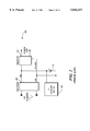
- FIG. 3 is a block diagram of the power conversion portion 330 of a preferred embodiment of the power supply used in the CATV system.
- the preferred embodiment system has redundant power bus 302, 303, 304 and 305 interconnecting the rectifier 306, the DC auxiliary source 308, the battery 310 and the inverter 320.
- the system further comprises a charger 316 and a filter 318.
- filter 318 is represented by a capacitor 320, though the filter 318 could be a more complex type of filter, commonly known in the industry.
- a novel aspect of the preferred embodiment is that the various units comprising the power conversion are diode isolated from each other.
- the inverter 320 is shown to consist of an H-bridge and two diodes 321 and 322.
- the rectifier 306 converts mains power 314 to DC, which power is transmitted to the inverter 320 for subsequent inversion and system power.
- the power from rectifier 306 does not directly charge the battery 310. Instead, battery 310 is charged by power conditioned by the charger 316.
- FIGS. 2 and 3 Other significant differences between this preferred embodiment and the prior art are evident by comparing FIGS. 2 and 3.
- a short circuit of the DC auxiliary source 308 would completely disrupt power to the subscribers.
- the power from the rectifier 306 and the auxiliary power source are isolated from each other.
- a short circuit of the DC auxiliary source 308 would have no adverse impact on the power supplied to the inverter 320, and thus would have no adverse impact on the power supplied to the subscribers.
- the isolation of the battery 310 from the rectifier 306 output power dispenses with the need to float charge battery 310, since the battery charging is independent of rectification. This allows the use of various charging regimens which may be more beneficial to the battery and extends its life.
- the subject invention results in increased battery life.
- One of the factors that affects battery life is how frequently the battery power is tapped.
- FIG. 2 even a short duration glitch or voltage drop on the AC mains power 314 would cause the battery 310 to have to supply power to the inverter 320.
- These short duration power glitches which may occur often, decrease the battery life.
- the system shown in FIG. 3 allows the battery 310 to be float charged at a voltage level that is lower than the AC mains voltage 314. Note that in FIG. 2, the battery 310 cannot be float charged at a voltage level lower than the rectifier 306 output, since the voltage across the battery is the same as rectifier 306 voltage output.
- the filter 318 will smooth out the power and continue supplying power to the inverter 320.
- the battery power will not be tapped unless the voltage output from the filter 318 drops below the battery voltage. This reduces the frequency in which battery 310 is tapped, thereby increasing its life.
- Supply 30 includes an AC distribution panel 32, input rectifiers 34, and power inverters 36.
- a fifth inverter 36R is a redundant inverter to replace one of the other inverters 36 if one becomes defective.
- AC distribution panel 32 delivers AC power, such as that supplied by electric utilities, to rectifiers 34.
- Rectifiers 34 convert the AC voltage to DC and supply it to inverters 36 through leads 60.
- the output of each inverter 36 is coupled through a combiner 40 to coaxial cables 24 to deliver output power.
- Combiner 40 also supplies broadband signals received from a trunk transceiver 44 to the coaxial cables 24.
- battery 50 may supply DC power to rectifiers 34, battery 50 may be used to provide DC power, instead of the AC power from distribution panel 32.
- Battery 50 supplies power to inverters 36 through leads 50A.
- a charger module 48 and motor generator 52 further enhance the reliability of battery.
- Generator 52 may operate on natural gas, propane, or gasoline.
- Charger module 48 monitors the battery voltage and activates motor generator 52 if it senses a voltage drop below a predetermined threshold, thus maintaining battery 50 at or near capacity.
- controller 46 exchanges control and status information with the inverters 36, charger 48, and generator 52 through bus 78.
- the communication protocol between controller 46 and devices 36, 48 and 52 is designed to support efficient, low baud rate communication, preferably up to 1200 baud, between the controller 46 and up to preferably sixteen devices, although more may be supported in accordance with the principles of the present invention.
- devices 36, 48, and 52 transmit when polled by controller 46.
- the communications may be interrupt driven or utilize a token passing protocol.
- each device 36, 48, and 52 is logically considered by controller 46 to consist of a memory array, such as 36M, 48M and 52M.
- Each memory array, such as memory array 52M is divided into working registers 54, non-volatile storage 56, and volatile storage 58.
- controller 46 accesses memory storage 58 through working registers 54.
- Control data written to working registers 54 is written to volatile storage 58 and echoed back to the controller 46 to enable immediate verification that data was transferred without error.
- Devices 36, 38 and 52 retrieve the control data from its corresponding memory array 36M, 48M or 52M, execute the control operation indicated by the control data, and acknowledge execution of the control operation by clearing at least one bit of the control data byte stored in memory array 36M, 48M or 52M.
- controller 46 obtains status information from devices 36, 48, and 52. Each device 36, 48 and 52 writes status data into its corresponding memory array 36M, 48M and 52M. Controller 46 monitors the operation of the power supply 30 through each memory array 36M, 48M and 52M, receives status information from each memory array 36M, 48M and 52M, and feeds back the status information to central office 12 through trunk transceiver 44 and trunk 20. Status data read from volatile storage 58 or non-volatile storage 56 results in the return of two identical data elements to the controller 46 for verifying data integrity.
- memory arrays 36M, 48M, and 52M are partitioned such that a corresponding device 36, 48, and 52 has an array of preferably byte size registers assigned to store status, control and device specific information.
- Column 82 represents a hexadecimal address for indexing into an array
- column 84 is a general description of an array register
- column 86 indicates controller 46 Read/Write access rights to an array register
- column 88 indicates the type of memory storage, volatile 56 or non-volatile 58, used for an array register.
- a memory array 36M, 48M and 52M further comprises a communication error register 90, a critical status register 92, a plurality of status registers 94, a plurality of control registers 96, a plurality of parametric measurement registers 98, a plurality of calibration factor registers 100, a plurality of calibrated parametric setting registers 102, and a plurality of uncalibrated parametric setting registers 104.
- a device 36, 48 and 52 initializes the contents of its error register 90 to zero at power-up. Upon detection of a communication error, device 36, 48 and 52 increment the contents of its corresponding error register 90.
- Controller 46 reads critical status register 92, preferably on a timed interval, to detect status changes in a device 36, 48, or 52 without analyzing the status registers 94.
- a device 36, 48 or 52 experiences a status change
- status data is written into one of the status registers 94.
- the device 36, 48, or 52 updates critical status register 92 to identify the type of detected status change.
- an update of the critical status register 92 occurs when power supply 30 experiences a loss or reduction in the power supplied to a consumer site 26.
- controller 46 modifies operation of a device 36, 38, or 52 by writing control data to a control register 96.
- Device 36, 48 and 52 stores parametric measurements, that is, actual output parameters of a device 36, 48 or 52 in registers 98. Parametric measurements are signed 2's complement binary numbers.
- the controller 46 reads a parametric measurement register 98 and multiplies the measurement by a bit weight to obtain a fixed or floating point value.
- error register 90, critical status register 92, status registers 94, control registers 96 and parametric measurement registers 98 are preferably stored in volatile memory 56.
- Nonvolatile memory 58 preferably contains parametric setting registers 102, 104, and calibration registers 100.
- Parametric settings are unsigned 2's complement binary numbers created by controller 46 to select a desired output of a device 36, 48, 52.
- Controller 46 divides a fixed or floating number by bit weight, rounds the result, and stores a signed calibration factor corresponding to the parametric readings and settings.
- Each parametric measurement found in register 98 and each calibrated parametric setting found in register 102 has a corresponding calibration factor.
- the contents of a calibration register 100 are added to the contents of a corresponding measurement 98, or setting 102 register to create a signed result which corrects for hardware offset errors.
- Table 1 illustrates system 10 data useful in monitoring output power to sites 26. Those skilled in the art appreciate that this list is not exhaustive and other types of data may be measured and monitored to control the power output and still achieve similar results.
- controller 46 has a scheduler 110 and a plurality of tasks 112, 114, 116 operating in a multi-tasking environment.
- Scheduler 110 executes each of the plurality of tasks 112, 114 and 116 for maximum utilization of the network bandwidth.
- Each task 112, 114 and 116 is assigned a priority level and a selected duration of time of the network bandwidth so that the controller 46 may efficiently determine critical changes in power distributed through the CATV system 10.
- the top priority task 112 continuously monitors critical status register 92 of each active inverter 36M. In the worst case, for a scan of the critical status 92 for each active inverter 36M, scheduler 110 schedules approximately 80% of the network bandwidth.
- the second priority task 114 monitors the critical status register 92 of the generator 52M. In worst case, scheduler 110 schedules approximately 10% of the network bandwidth for monitoring the status of generator 52. For other less time critical functions, such as monitoring the battery charger 48, controlling the battery heater, or executing a power-up sequence, scheduler 110 schedules the remaining network bandwidth.
- controller 46 scans the contents of the critical status register 92 of an active inverter's memory array 36M for a change in the status of the inverter 36 (Step 120). If a status change is not detected, controller 46 advances to the next active inverter's memory array 36M (Step 122). If a status change is not reported by any active inverter 36, control returns to the scheduler 110. If a status change is detected (Step 124), controller 46 must first interrogate the appropriate status bytes (Steps 126, 142 and 154, in FIGS.
- Step 128 determines if the change is benign; that is, if the change does not require intervention of service by controller 46 (Step 128); or whether the change requires further analysis by controller 46. Changes are considered benign as long as output power, even unipolar power, is being supplied to the loads. Benign changes are handled locally by inverter 36 without requiring further handling by the first priority task 112 (Step 130). Pseudocode for the INV -- HANDLER subroutine is shown in Table II.
- the status data for an inverter 36 may include a signal that an inverter's 36 negative return or positive return switch is shorted or one or more of the inverters attempted to switch output polarities at the wrong time.
- the inverter 36 then waits for a predetermined period to verify if the SYNC line corresponding to the error polarity goes high. If the SYNC line goes high within a time-out period, a valid error occurred and the inverter will lock itself in the non-errored polarity and attempt to restart the output in unipolar mode.
- the inverter 36 If, on the other hand, the line stays low for the time-out period, the error was probably set by noise, or one or more of the inverters 36 failed. In this case, a single retry of the same polarity is issued to inverter 36. If the restart is successful then the status is cleared. If the error occurs a second time, the inverter 36 will lock itself in the non-errored polarity and attempt to restart the output in unipolar mode. If the inverter 36 locks itself in the non-errored polarity and attempts to restart the output in unipolar mode and an error results, the inverter 36 will disable its output and wait for intervention by the first priority task 112. If no error occurs, the output will remain in unipolar mode until intervention by the first priority task 112.
- controller 46 calls the HANDLE -- SELF -- INHIBIT subroutine (Step 133). If the status byte 94 indicates that the inverter heatsink or inverter module ambient temperature reaches a critical level (Step 134), controller 46 calls the HANDLE -- CRIT -- TEMP subroutine (Step 135). If the status byte 94 indicates an over-current condition with the inverter 36 (Step 136), controller 46 calls the OVER -- CURRENT subroutine (Step 137).
- Step 138 If the status byte 94 indicates a run-down battery and the inverter 36 is in battery mode (Step 138), inverter 36 is enabled by a RESET signal from controller 46 (Step 139). If the status byte 94 indicates an overvoltage condition with the inverter 36 (Step 140), controller 46 calls the OVER -- VOLTAGE subroutine (Step 141).
- controller 46 if a status change is detected in the second status byte 94 (Step 142), controller 46 interrogates each bit in the status register 94 to identify the changed condition. If the status byte 94 indicates the H-bridge return is via the positive polarity switch (Step 144), controller calls the HANDLE -- HBRIDGE subroutine (Step 145). If the status byte 94 indicates that the inverter 36 is operating in unipolar mode (Step 146), controller 46 calls the HANDLE -- UNIPOLAR subroutine (Step 147).
- controller 46 calls the SYNC -- TIME -- OUT subroutine (Step 149).
- Step 150 If status byte 94 indicates a time out while the inverter waits for the POS/NEG sync lines to go high (Step 150), inverter 36 defaults to unipolar mode (Step 151). If the status byte 94 indicates there is no measurable load on the inverter 36 output due to a load failure, a redundancy failure, or open output circuit breaker (Step 152), controller 46 calls the NO -- LOAD subroutine (Step 153).
- controller 46 if a status change is detected in the third status byte 94 (Step 154), controller 46 interrogates each bit in the status register 94 to identify the changed condition. If the status byte 94 indicates a de-energized relay as the result of an inverter 36 electrical malfunction (Step 156) controller 46 calls the HANDLE -- RELAY subroutine (Step 157). If the status byte 94 indicates a de-energized SCR due to the different potentials of the rectifier bulk DC capacitors and the inverter bulk DC filter capacitors (Step 158), controller 46 calls the HANDLE -- SCR subroutine (Step 159). If the status byte 94 indicates the inverter plug is disconnected (Step 160), controller 46 calls the HANDLE -- PLUG subroutine (Step 161).
- controller 46 scans the contents of the critical status register 92 (Step 200) of the generators memory array 52M for a change in the status of the generator 52 (Step 202). If a status change is not detected, control returns to the scheduler 110 (Step 204). If a status change is detected (Step 202), controller 46 must first interrogate the status byte and determine if the change is benign; that is, the change does not require intervention or service by controller 46, or whether the change requires further analysis by controller 46. If the status byte 94 indicates a natural gas leak (Step 206) controller 46 calls the HANDLE -- GAS -- LEAK subroutine (Step 207). If the status byte 94 indicates an abnormal condition that results in a failure of the generator (Step 208), controller 46 calls the HANDLE -- GEN -- FAIL subroutine (Step 209).
- controller 46 calls the HANDLE -- WATER -- DET subroutine (Step 211).
- controller 46 calls the GEN -- RUN subroutine (Step 213). If the status byte 94 indicates a starting battery charger error (Step 214), controller 46 calls the HANDLE -- CHARGER subroutine (Step 215). If the status byte 94 indicates a loss of natural gas pressure (Step 216), controller 46 calls the HANDLE -- GAS -- LOSS subroutine (Step 217). If the status byte 94 indicates an open enclosure door (Step 218), controller 46 calls the DOOR -- OPEN subroutine (Step 219).
- a third priority level task 114 is assigned the least amount of execution time.
- the scheduler 110 will handle requests for service by a third priority task 114 on a first come, first served basis.
- a third priority task 114 may include a task which interrogates the battery charger 48 for status changes.
- a flow chart for such a third priority task 114 executed by controller 46 is shown in FIG. 10. Initially, controller 46 scans the contents of the critical status register 92 (Step 240) of the battery charger's memory array 48M for a change in the status of the battery charger 48 (Step 242). If a status change is not detected, control returns to the scheduler 110 (Step 244).
- controller 46 If a status change is detected (Step 242), controller 46 must first interrogate the status byte 94 and determine if the change is benign; that is, the change does not require intervention or service by the controller 46, or whether the change requires further analysis by the controller 46. If the status byte 94 indicates the output current limit relay is de-energized (Step 246), controller 46 calls the HANDLE -- DEENERGIZED -- OUTRLY subroutine (Step 247). If the input current limit relay is de-energized (Step 248), controller 46 calls the HANDLE -- DEENERGIZED -- INRLY subroutine (Step 249).
- controller 46 calls the HANDLE -- CHARGER -- INHIBIT subroutine (Step 251). If the manual reset button is depressed (Step 252), controller 46 calls the MANUAL -- RESET subroutine (Step 253). If the overvoltage protection circuit operates (Step 254), controller 46 calls the OVER -- VOLTAGE subroutine (Step 255). If the charger enables a fan (Step 256), the controller 46 calls the FAN -- ENABLED subroutine (Step 257).
- controller 46 calls the VOLT -- DROP subroutine (Step 259). If the battery is discharging (Step 260), controller 46 calls the BATT -- DISCHARGE subroutine (Step 261). If the charger plug is disconnected, (Step 262), controller 46 calls the CHARGER -- UNPLUG subroutine (Step 263). If there is a failure of the fan output fuse (Step 264), controller 46 calls the FAN -- OUT -- FUSE subroutine (Step 265).
- controller 46 calls the INVALID -- PAR subroutine (Step 267). If the rectifier circuit breaker is tripped or the rectifier is unplugged (Step 268), controller 46 calls the RECT -- BREAK -- TRIP subroutine (Step 269). If the status change indicates an open fuse (Step 270), controller 46 calls the OPEN -- FUSE subroutine (Step 271).
- a third priority task 116 may also include a routine that analyzes the rectifier currents to detect failure of a rectifier or its AC input. Further, a third priority task 116 may include a battery thermal management routine responsible for analysis of battery compartment temperature compared to outdoor air temperature and controlling the battery heaters to maintain a minimum temperature on the battery case. If where the outdoor air is cooler than the battery compartment air and the battery compartment air temperature is higher than a predetermined upper limit, a routine enables the battery compartment ventilation fan. Finally, a third priority task 116 may include a battery charging profile management routine responsible for modifying the battery charger output to optimize battery float levels versus temperature and to implement various charging schemes. While the battery is discharging, this routine accumulates discharging amp-hours.
Abstract
Description
                                  TABLE I
__________________________________________________________________________
       CHARGER    INVERTER     GENERATOR
__________________________________________________________________________
       de-energized output
                  inverter electrical
                               natural gas leak,
Status current limit relay,
                  malfunction, generator failure,
Data   de-energized input
                  inverter output inhibited
                               open enclosure door,
       current limit relay,
                  critical heatsink or ambient
                               water in generator
       charger inhibited,
                  temperature, cabin,
       charger running in
                  output inhibited due to
                               generator running,
       boost mode,
                  overcurrent, generator charging
       manual reset switch
                  inverter output inhibited due
                               error,
       selected,  to run-down battery,
                               loss of natural gas
       real-time status of the
                  output inhibited due to
                               pressure,
       manual reset switch,
                  overvoltage error,
                               maintenance service
       active overvoltage
                  H-bridge return via positive
                               required.
       protection circuit,
                  polarity switch,
       critical heatsink or
                  inverter operating in unipolar
       ambient temperature,
                  mode,
       fan enabled,
                  time-out while waiting for the
       input voltage drop
                  SYNC signal time-out while
       below threshold level,
                  waiting for POS/NEG signal,
       discharging battery,
                  no measurable load on the
       disconnected plug,
                  inverter output,
       blown fuse,
                  de-energized input current
       out-of-range setup
                  limit SCRs,
       parameter, disconnected plug,
       rectifier unplugged,
                  visual indicator lamp enabled
       visual indicator lamp
       enabled
       inhibit charger output,
                  inhibit inverter output,
                               start generator,
Control Data
       enable visual indicator
                  select unipolar output
                               emergency generator
       lamp       operation,   shutdown,
                  start inverter in negative
                               enter power down
                  polarity,    mode
                  enable visual indicator lamp
Parametric
       input capacitor voltage,
                  battery input voltage,
                               generator starting
Measurements
       output capacitor voltage,
                  H-bridge input voltage,
                               battery voltage
       output current to battery,
                  output crest current,
       battery discharge
                  output crest voltage,
       current, heatsink
                  heatsink temperature,
       temperature,
                  internal air temperature
       internal temperature,
       rectifier output currents,
       rectifier circuit breaker
       voltage drop
Parametric
       output voltage,
                  peak current limit setting,
Settings
       output current limit,
                  output crest voltage setting,
       DAC output half-cycle time,
                  output rise time, shutdown
                  threshold,
                  current limit shutdown delay,
                  retry delay,
                  retry count
__________________________________________________________________________
              TABLE II
______________________________________
IF (inverter's return switch shorted or improper output polarity switch)
 {
 Set SYNCH.sub.-- TIMEOUT counter;
 Wait for SYNC line high signal;
 IF (SYNCH TIMEOUT>O)
  {valid error; inverter restarts output in unipolar mode;}
 ELSE
  {retry inverter;}
  IF (retry successful)
  {clear STATUS bit;}
  ELSE
  {restart output in unipolar mode;}
  IF (error)
   {inhibit inverter output; }
 }
______________________________________
Claims (32)
Priority Applications (3)
| Application Number | Priority Date | Filing Date | Title |
|---|---|---|---|
| US08/802,026 US5844327A (en) | 1996-08-21 | 1997-02-18 | Apparatus and method for optimizing power distributed in a broadband signal system |
| AU40801/97A AU4080197A (en) | 1996-08-21 | 1997-08-21 | Apparatus and method for optimizing power distributed in a broadband signal system |
| PCT/US1997/014714 WO1998008288A1 (en) | 1996-08-21 | 1997-08-21 | Apparatus and method for optimizing power distributed in a broadband signal system |
Applications Claiming Priority (2)
| Application Number | Priority Date | Filing Date | Title |
|---|---|---|---|
| US2424896P | 1996-08-21 | 1996-08-21 | |
| US08/802,026 US5844327A (en) | 1996-08-21 | 1997-02-18 | Apparatus and method for optimizing power distributed in a broadband signal system |
Publications (1)
| Publication Number | Publication Date |
|---|---|
| US5844327A true US5844327A (en) | 1998-12-01 |
Family
ID=26698230
Family Applications (1)
| Application Number | Title | Priority Date | Filing Date |
|---|---|---|---|
| US08/802,026 Expired - Lifetime US5844327A (en) | 1996-08-21 | 1997-02-18 | Apparatus and method for optimizing power distributed in a broadband signal system |
Country Status (3)
| Country | Link |
|---|---|
| US (1) | US5844327A (en) |
| AU (1) | AU4080197A (en) |
| WO (1) | WO1998008288A1 (en) |
Cited By (35)
| Publication number | Priority date | Publication date | Assignee | Title |
|---|---|---|---|---|
| WO1999028847A1 (en) * | 1997-11-28 | 1999-06-10 | Diebold, Incorporated | Financial transaction apparatus and method that identifies an authorized user's appearance and voice |
| WO2000034836A1 (en) * | 1998-12-11 | 2000-06-15 | Caterpillar Inc. | An operating center for industrial equipment |
| GB2355350A (en) * | 1999-10-15 | 2001-04-18 | Alpha Tech Inc | Multiple output UPS |
| FR2808905A1 (en) * | 2000-05-15 | 2001-11-16 | Paul Ortais | DEVICE FOR DATA TRANSFER ON AN INTERMITTENT DIRECT CURRENT NETWORK |
| US20030197485A1 (en) * | 2002-04-22 | 2003-10-23 | Michael Miller | Battery adapter |
| US6735704B1 (en) | 2000-10-20 | 2004-05-11 | International Business Machines Corporation | Autonomic control of power subsystems in a redundant power system |
| US20050057100A1 (en) * | 2003-09-12 | 2005-03-17 | Crusius Steven Carl | DC power backup |
| US20050085212A1 (en) * | 2003-10-16 | 2005-04-21 | Arkadiy Peker | High power architecture for power over Ethernet |
| US20050122140A1 (en) * | 2003-10-16 | 2005-06-09 | Arkadiy Peker | High power architecture for power over Ethernet |
| US6941274B1 (en) * | 1997-11-28 | 2005-09-06 | Diebold, Incorporated | Automated transaction machine |
| US20050194838A1 (en) * | 2004-03-03 | 2005-09-08 | Evans Wetmore | System and method for reducing radiation when distributing broadband communication signals over power lines |
| US20050197094A1 (en) * | 2003-10-16 | 2005-09-08 | Yair Darshan | High power classification for power over Ethernet |
| WO2005107035A2 (en) * | 2004-04-30 | 2005-11-10 | Siemens Aktiengesellschaft | Power supply device |
| US20060019629A1 (en) * | 2004-01-22 | 2006-01-26 | Yuval Berson | Redundant powered device circuit |
| WO2006052217A1 (en) * | 2004-11-09 | 2006-05-18 | St Electronics (Info-Comm Systems) Pte. Ltd. | Redundant power supply for power-over-ethernet |
| US20060103137A1 (en) * | 2000-08-14 | 2006-05-18 | Aloys Wobben | Wind power installation |
| US20060265524A1 (en) * | 2003-04-09 | 2006-11-23 | Volker Fricke | Method and apparatus for data logging |
| US20070135970A1 (en) * | 2005-12-08 | 2007-06-14 | General Electric Company | System and method for providing reactive power support with distributed energy resource inverter |
| US20080078436A1 (en) * | 2006-09-28 | 2008-04-03 | Jack Nachamkin | Integrated voltaic energy system |
| US20080106100A1 (en) * | 2006-11-06 | 2008-05-08 | Abb Oy | Method and arrangement in wind power plant |
| US20100009724A1 (en) * | 2008-07-10 | 2010-01-14 | Steve Fischer | Cell site power generation |
| US7962772B2 (en) | 2008-02-07 | 2011-06-14 | Ainet Registry, Llc | Backup power system and method |
| US20110140683A1 (en) * | 2008-08-17 | 2011-06-16 | Hulda Transformers | Power booster for cable systems |
| US20130141051A1 (en) * | 2011-12-05 | 2013-06-06 | Jin-Wook Kang | Energy storage system and method for controlling the same |
| US8575779B2 (en) | 2010-02-18 | 2013-11-05 | Alpha Technologies Inc. | Ferroresonant transformer for use in uninterruptible power supplies |
| EA020927B1 (en) * | 2011-10-13 | 2015-02-27 | Сергей Петрович Сергеев | United electrical supply device with the dc bus |
| US8983546B2 (en) | 2009-07-24 | 2015-03-17 | T-Mobile Usa, Inc. | Rectifier circuit management system, for use in cell site power systems |
| US9030045B2 (en) | 2011-01-23 | 2015-05-12 | Alpha Technologies Inc. | Switching systems and methods for use in uninterruptible power supplies |
| US9234916B2 (en) | 2012-05-11 | 2016-01-12 | Alpha Technologies Inc. | Status monitoring cables for generators |
| US9543758B1 (en) * | 2013-11-22 | 2017-01-10 | Sprint Communications Company L.P. | Adaptive battery power distribution to remote radio heads in long term evolution (LTE) networks |
| US10074981B2 (en) | 2015-09-13 | 2018-09-11 | Alpha Technologies Inc. | Power control systems and methods |
| US10110387B2 (en) | 2013-06-27 | 2018-10-23 | Philips Lighting Holding B.V. | Powered device and power distribution system comprising the powered device |
| US10381867B1 (en) | 2015-10-16 | 2019-08-13 | Alpha Technologeis Services, Inc. | Ferroresonant transformer systems and methods with selectable input and output voltages for use in uninterruptible power supplies |
| US10635122B2 (en) | 2017-07-14 | 2020-04-28 | Alpha Technologies Services, Inc. | Voltage regulated AC power supply systems and methods |
| US11301024B2 (en) | 2017-02-03 | 2022-04-12 | Shure Acquisition Holdings, Inc. | System and methods for detecting and monitoring power characteristics amongst connected devices in a conferencing system |
Families Citing this family (6)
| Publication number | Priority date | Publication date | Assignee | Title |
|---|---|---|---|---|
| US7827418B2 (en) * | 2005-01-25 | 2010-11-02 | Linear Technology Corporation | Controlling power distribution among multiple wires in communication cable |
| CN100486287C (en) * | 2005-04-30 | 2009-05-06 | 华为技术有限公司 | Remote power supply system |
| ITBO20090822A1 (en) * | 2009-12-24 | 2011-06-25 | Stilrossi Sas Di Lino Rossi & C | INTEGRATED DEVICE WITH DOUBLE INVERTER |
| CN102170169A (en) * | 2011-03-30 | 2011-08-31 | 株洲南车时代电气股份有限公司 | Power-supply system of vehicle-mounted auxiliary inverter power source |
| US10396554B2 (en) * | 2017-02-13 | 2019-08-27 | The Boeing Company | Power distribution control within a modular converter system using efficiency calculations |
| CN110048449B (en) * | 2019-03-19 | 2021-12-10 | 尚特杰电力科技有限公司 | Micro-grid off-grid and on-grid rapid conversion system and method |
Citations (12)
| Publication number | Priority date | Publication date | Assignee | Title |
|---|---|---|---|---|
| US3909560A (en) * | 1973-03-05 | 1975-09-30 | Kabel Metallwerke Ghh | Method and system for providing power to booster amplifiers in h.f. cable network |
| FR2491704A1 (en) * | 1980-10-03 | 1982-04-09 | Constr Telephoniques | Uses differential amplifier and generator - giving spaced voltage pulses to power line to reduce consumption and avoid noise generation |
| WO1990007235A1 (en) * | 1988-12-13 | 1990-06-28 | Stern Telecommunications Corporation | Cable systems or the like |
| US5332927A (en) * | 1991-02-11 | 1994-07-26 | Best Power Technology, Inc. | Power supply system for a telecommunication system |
| US5410720A (en) * | 1992-10-28 | 1995-04-25 | Alpha Technologies | Apparatus and methods for generating an AC power signal for cable TV distribution systems |
| US5436822A (en) * | 1992-07-31 | 1995-07-25 | Scientific-Atlanta, Inc. | Polarity reversing DC power supply for remotely located equipment |
| GB2288891A (en) * | 1994-04-18 | 1995-11-01 | Power Guard Inc | RMS regulation of trapezoidal voltage |
| US5467384A (en) * | 1993-05-28 | 1995-11-14 | U S West Advanced Technologies, Inc. | Method and apparatus for providing power to a coaxial cable network |
| US5477091A (en) * | 1991-11-27 | 1995-12-19 | Merlin Gerin | High quality electrical power distribution system |
| US5483108A (en) * | 1992-06-29 | 1996-01-09 | France Telecom Etablissement Autonome De Droit Public | Uninterrupted distributed storage supply system |
| US5592030A (en) * | 1993-08-19 | 1997-01-07 | Adahan; Carmeli | Power supply for energizing DC load from AC or DC source |
| US5642002A (en) * | 1993-10-29 | 1997-06-24 | Alpha Technologies | Apparatus and methods for generating uninterruptible AC power signals |
-
1997
- 1997-02-18 US US08/802,026 patent/US5844327A/en not_active Expired - Lifetime
- 1997-08-21 AU AU40801/97A patent/AU4080197A/en not_active Abandoned
- 1997-08-21 WO PCT/US1997/014714 patent/WO1998008288A1/en active Application Filing
Patent Citations (12)
| Publication number | Priority date | Publication date | Assignee | Title |
|---|---|---|---|---|
| US3909560A (en) * | 1973-03-05 | 1975-09-30 | Kabel Metallwerke Ghh | Method and system for providing power to booster amplifiers in h.f. cable network |
| FR2491704A1 (en) * | 1980-10-03 | 1982-04-09 | Constr Telephoniques | Uses differential amplifier and generator - giving spaced voltage pulses to power line to reduce consumption and avoid noise generation |
| WO1990007235A1 (en) * | 1988-12-13 | 1990-06-28 | Stern Telecommunications Corporation | Cable systems or the like |
| US5332927A (en) * | 1991-02-11 | 1994-07-26 | Best Power Technology, Inc. | Power supply system for a telecommunication system |
| US5477091A (en) * | 1991-11-27 | 1995-12-19 | Merlin Gerin | High quality electrical power distribution system |
| US5483108A (en) * | 1992-06-29 | 1996-01-09 | France Telecom Etablissement Autonome De Droit Public | Uninterrupted distributed storage supply system |
| US5436822A (en) * | 1992-07-31 | 1995-07-25 | Scientific-Atlanta, Inc. | Polarity reversing DC power supply for remotely located equipment |
| US5410720A (en) * | 1992-10-28 | 1995-04-25 | Alpha Technologies | Apparatus and methods for generating an AC power signal for cable TV distribution systems |
| US5467384A (en) * | 1993-05-28 | 1995-11-14 | U S West Advanced Technologies, Inc. | Method and apparatus for providing power to a coaxial cable network |
| US5592030A (en) * | 1993-08-19 | 1997-01-07 | Adahan; Carmeli | Power supply for energizing DC load from AC or DC source |
| US5642002A (en) * | 1993-10-29 | 1997-06-24 | Alpha Technologies | Apparatus and methods for generating uninterruptible AC power signals |
| GB2288891A (en) * | 1994-04-18 | 1995-11-01 | Power Guard Inc | RMS regulation of trapezoidal voltage |
Cited By (74)
| Publication number | Priority date | Publication date | Assignee | Title |
|---|---|---|---|---|
| US6941274B1 (en) * | 1997-11-28 | 2005-09-06 | Diebold, Incorporated | Automated transaction machine |
| US6023688A (en) * | 1997-11-28 | 2000-02-08 | Diebold, Incorporated | Transaction apparatus and method that identifies an authorized user by appearance and voice |
| US20100102118A1 (en) * | 1997-11-28 | 2010-04-29 | Natarajan Ramachandran | Banking transaction machine that operates responsive to data bearing records |
| US8011572B2 (en) | 1997-11-28 | 2011-09-06 | Diebold, Incorporated | Banking transaction machine that operates responsive to data bearing records |
| WO1999028847A1 (en) * | 1997-11-28 | 1999-06-10 | Diebold, Incorporated | Financial transaction apparatus and method that identifies an authorized user's appearance and voice |
| WO2000034836A1 (en) * | 1998-12-11 | 2000-06-15 | Caterpillar Inc. | An operating center for industrial equipment |
| GB2355350A (en) * | 1999-10-15 | 2001-04-18 | Alpha Tech Inc | Multiple output UPS |
| US6288916B1 (en) | 1999-10-15 | 2001-09-11 | Alpha Technologies, Inc. | Multiple output uninterruptible alternating current power supplies for communications system |
| GB2355350B (en) * | 1999-10-15 | 2004-04-14 | Alpha Tech Inc | Multiple output uninterruptible power supplies for communications systems |
| FR2808905A1 (en) * | 2000-05-15 | 2001-11-16 | Paul Ortais | DEVICE FOR DATA TRANSFER ON AN INTERMITTENT DIRECT CURRENT NETWORK |
| EP1156594A1 (en) * | 2000-05-15 | 2001-11-21 | Paul Ortais | Data transfer over an intermittently DC powered network |
| US7102248B2 (en) * | 2000-08-14 | 2006-09-05 | Aloys Wobben | Wind power installation |
| EP1312153B1 (en) * | 2000-08-14 | 2009-01-21 | Aloys Wobben | Wind power plant |
| US20060103137A1 (en) * | 2000-08-14 | 2006-05-18 | Aloys Wobben | Wind power installation |
| US6735704B1 (en) | 2000-10-20 | 2004-05-11 | International Business Machines Corporation | Autonomic control of power subsystems in a redundant power system |
| US20030197485A1 (en) * | 2002-04-22 | 2003-10-23 | Michael Miller | Battery adapter |
| US7610398B2 (en) * | 2003-04-09 | 2009-10-27 | International Business Machines Corporation | Method and system for data logging |
| US20100042683A1 (en) * | 2003-04-09 | 2010-02-18 | International Business Machines Corporation | System for data logging |
| US20060265524A1 (en) * | 2003-04-09 | 2006-11-23 | Volker Fricke | Method and apparatus for data logging |
| US8046406B2 (en) | 2003-04-09 | 2011-10-25 | International Business Machines Corporation | System for data logging |
| GB2406978B (en) * | 2003-09-12 | 2006-07-19 | Chamberlain Group Inc | DC power backup |
| US20050057100A1 (en) * | 2003-09-12 | 2005-03-17 | Crusius Steven Carl | DC power backup |
| GB2406978A (en) * | 2003-09-12 | 2005-04-13 | Chamberlain Group Inc | DC power backup for a barrier movement operator |
| US7786619B2 (en) | 2003-09-12 | 2010-08-31 | The Chamberlain Group, Inc. | DC power backup |
| US7492059B2 (en) | 2003-10-16 | 2009-02-17 | Microsemi Corp.—Analog Mixed Signal Group Ltd. | High power architecture for power over ethernet |
| US7299368B2 (en) | 2003-10-16 | 2007-11-20 | Microsemi Corp.-Analog Mixed Signal Group Ltd. | High power architecture for power over Ethernet |
| US20050197094A1 (en) * | 2003-10-16 | 2005-09-08 | Yair Darshan | High power classification for power over Ethernet |
| US20050085212A1 (en) * | 2003-10-16 | 2005-04-21 | Arkadiy Peker | High power architecture for power over Ethernet |
| US7460889B2 (en) | 2003-10-16 | 2008-12-02 | Microsemi Corp.—Analog Mixed Signal Group Ltd. | High power classification for power over Ethernet |
| US20050122140A1 (en) * | 2003-10-16 | 2005-06-09 | Arkadiy Peker | High power architecture for power over Ethernet |
| US20060019629A1 (en) * | 2004-01-22 | 2006-01-26 | Yuval Berson | Redundant powered device circuit |
| US7509114B2 (en) | 2004-01-22 | 2009-03-24 | Microsemi Corp. - Analog Mixed Signal Group Ltd. | Redundant powered device circuit |
| US7088232B2 (en) * | 2004-03-03 | 2006-08-08 | Evans Wetmore | System and method for reducing radiation when distributing broadband communication signals over power lines |
| US20050194838A1 (en) * | 2004-03-03 | 2005-09-08 | Evans Wetmore | System and method for reducing radiation when distributing broadband communication signals over power lines |
| WO2005107035A2 (en) * | 2004-04-30 | 2005-11-10 | Siemens Aktiengesellschaft | Power supply device |
| US7631204B2 (en) | 2004-04-30 | 2009-12-08 | Siemens Aktiengessellschaft | Power supply device having communication channels with different types of communication connections |
| WO2005107035A3 (en) * | 2004-04-30 | 2006-01-26 | Siemens Ag | Power supply device |
| US20080086649A1 (en) * | 2004-04-30 | 2008-04-10 | Dieter Hublitz | Power Supply Device |
| US20080100141A1 (en) * | 2004-11-09 | 2008-05-01 | St. Electronics (Info-Comm Stystems) Pte.Ltd. | Redundant Power Supply For Power-Over-Ethernet |
| WO2006052217A1 (en) * | 2004-11-09 | 2006-05-18 | St Electronics (Info-Comm Systems) Pte. Ltd. | Redundant power supply for power-over-ethernet |
| US20070135970A1 (en) * | 2005-12-08 | 2007-06-14 | General Electric Company | System and method for providing reactive power support with distributed energy resource inverter |
| US7508173B2 (en) * | 2005-12-08 | 2009-03-24 | General Electric Company | System and method for providing reactive power support with distributed energy resource inverter |
| US20080078436A1 (en) * | 2006-09-28 | 2008-04-03 | Jack Nachamkin | Integrated voltaic energy system |
| US7893346B2 (en) * | 2006-09-28 | 2011-02-22 | Jack Nachamkin | Integrated voltaic energy system |
| US8097970B2 (en) * | 2006-11-06 | 2012-01-17 | Abb Oy | Method and arrangement in wind power plant |
| US20080106100A1 (en) * | 2006-11-06 | 2008-05-08 | Abb Oy | Method and arrangement in wind power plant |
| US7962772B2 (en) | 2008-02-07 | 2011-06-14 | Ainet Registry, Llc | Backup power system and method |
| US10433245B2 (en) | 2008-07-10 | 2019-10-01 | T-Mobile Usa, Inc. | Cell site power generation |
| US20100009724A1 (en) * | 2008-07-10 | 2010-01-14 | Steve Fischer | Cell site power generation |
| US11082917B2 (en) | 2008-07-10 | 2021-08-03 | T-Mobile Usa, Inc. | Cell site power generation |
| US8729732B2 (en) * | 2008-07-10 | 2014-05-20 | T-Mobile Usa, Inc. | Cell site power generation |
| US9386518B2 (en) | 2008-07-10 | 2016-07-05 | T-Mobile Usa, Inc. | Cell site power generation |
| US8415822B2 (en) | 2008-08-17 | 2013-04-09 | Hulda Transformers | Power booster for cable systems |
| US20110140683A1 (en) * | 2008-08-17 | 2011-06-16 | Hulda Transformers | Power booster for cable systems |
| US8983546B2 (en) | 2009-07-24 | 2015-03-17 | T-Mobile Usa, Inc. | Rectifier circuit management system, for use in cell site power systems |
| US9603089B2 (en) | 2009-07-24 | 2017-03-21 | T-Mobile Usa, Inc. | Rectifier circuit management system, such as for use in cell site power systems |
| US8575779B2 (en) | 2010-02-18 | 2013-11-05 | Alpha Technologies Inc. | Ferroresonant transformer for use in uninterruptible power supplies |
| US10819144B2 (en) | 2010-02-18 | 2020-10-27 | Alpha Technologies Services, Inc. | Ferroresonant transformer for use in uninterruptible power supplies |
| US9633781B2 (en) | 2010-02-18 | 2017-04-25 | Alpha Technologies Inc. | Ferroresonant transformer for use in uninterruptible power supplies |
| US9812900B2 (en) | 2011-01-23 | 2017-11-07 | Alpha Technologies Inc. | Switching systems and methods for use in uninterruptible power supplies |
| US10355521B2 (en) | 2011-01-23 | 2019-07-16 | Alpha Technologies Services, Inc. | Switching systems and methods for use in uninterruptible power supplies |
| US9030045B2 (en) | 2011-01-23 | 2015-05-12 | Alpha Technologies Inc. | Switching systems and methods for use in uninterruptible power supplies |
| EA020927B1 (en) * | 2011-10-13 | 2015-02-27 | Сергей Петрович Сергеев | United electrical supply device with the dc bus |
| US9362750B2 (en) * | 2011-12-05 | 2016-06-07 | Samsung Sdi Co., Ltd. | Energy storage system and method for controlling the same |
| US20130141051A1 (en) * | 2011-12-05 | 2013-06-06 | Jin-Wook Kang | Energy storage system and method for controlling the same |
| US9234916B2 (en) | 2012-05-11 | 2016-01-12 | Alpha Technologies Inc. | Status monitoring cables for generators |
| US10110387B2 (en) | 2013-06-27 | 2018-10-23 | Philips Lighting Holding B.V. | Powered device and power distribution system comprising the powered device |
| RU2672619C2 (en) * | 2013-06-27 | 2018-11-16 | Филипс Лайтинг Холдинг Б.В. | Powered device and power distribution system comprising powered device |
| US9543758B1 (en) * | 2013-11-22 | 2017-01-10 | Sprint Communications Company L.P. | Adaptive battery power distribution to remote radio heads in long term evolution (LTE) networks |
| US10074981B2 (en) | 2015-09-13 | 2018-09-11 | Alpha Technologies Inc. | Power control systems and methods |
| US10790665B2 (en) | 2015-09-13 | 2020-09-29 | Alpha Technologies Services, Inc. | Power control systems and methods |
| US10381867B1 (en) | 2015-10-16 | 2019-08-13 | Alpha Technologeis Services, Inc. | Ferroresonant transformer systems and methods with selectable input and output voltages for use in uninterruptible power supplies |
| US11301024B2 (en) | 2017-02-03 | 2022-04-12 | Shure Acquisition Holdings, Inc. | System and methods for detecting and monitoring power characteristics amongst connected devices in a conferencing system |
| US10635122B2 (en) | 2017-07-14 | 2020-04-28 | Alpha Technologies Services, Inc. | Voltage regulated AC power supply systems and methods |
Also Published As
| Publication number | Publication date |
|---|---|
| WO1998008288A1 (en) | 1998-02-26 |
| AU4080197A (en) | 1998-03-06 |
Similar Documents
| Publication | Publication Date | Title |
|---|---|---|
| US5844327A (en) | Apparatus and method for optimizing power distributed in a broadband signal system | |
| US6854065B2 (en) | Loadshedding uninterruptible power supply | |
| US7269753B2 (en) | Mapping power system components | |
| US6628207B1 (en) | Method and apparatus for detecting and reporting a power outage | |
| JP4481506B2 (en) | Improved structured cable system | |
| JP4691036B2 (en) | Power conversion for variable load | |
| US8344546B2 (en) | Power supply unit directly connected to backup direct current power source | |
| JP2006500897A (en) | Power management system for variable load | |
| KR20080099320A (en) | Systems and methods for providing and managing high-availability power infrastructures with flexible load prioritization | |
| US7334139B2 (en) | Power supply control apparatus, power supply control system, and administration apparatus | |
| ZA200106533B (en) | Improved structure cabling system. | |
| US20050271128A1 (en) | Distributed SCADA system for remote monitoring and control of access points utilizing an intelligent uninterruptible power supply system for a WISP network | |
| JP6194262B2 (en) | DC power supply device and power supply control method | |
| US20220224152A1 (en) | Communication power supply system | |
| US20160294188A1 (en) | Energy supply system and conductor loop enclosure | |
| JP2001069668A (en) | Power management device | |
| CN114421601B (en) | Power supply system and control method and control device thereof | |
| TW201712995A (en) | DC backup equipment | |
| US9979228B2 (en) | Energy management apparatus and method of controlling the same | |
| KR20180114739A (en) | Method for managing Energy Storage System | |
| CN108899911B (en) | Direct current power transformation system | |
| CN211880158U (en) | Power supply system | |
| US20230246479A1 (en) | Power disconnect system and method | |
| CN211628042U (en) | Wisdom street lamp monitored control system | |
| CN108988341B (en) | Power distribution equipment fault adjusting method and device |
Legal Events
| Date | Code | Title | Description |
|---|---|---|---|
| AS | Assignment |
Owner name: ANTEC CORPORATION, ILLINOIS Free format text: ASSIGNMENT OF ASSIGNORS INTEREST;ASSIGNOR:BATSON, JOHN GARY;REEL/FRAME:008658/0848 Effective date: 19961126 |
|
| STCF | Information on status: patent grant |
Free format text: PATENTED CASE |
|
| AS | Assignment |
Owner name: CIT GROUP BUSINESS/CREDIT, INC., THE, GEORGIA Free format text: GRANT OF PATENT SECURITY INTEREST;ASSIGNOR:ARRIS INTERNATIONAL, INC.;REEL/FRAME:012059/0793 Effective date: 20010803 |
|
| FPAY | Fee payment |
Year of fee payment: 4 |
|
| AS | Assignment |
Owner name: ARRIS INTERNATIONAL, INC., GEORGIA Free format text: RELEASE OF SECURITY INTEREST IN PATENTS;ASSIGNOR:CIT GROUP/BUSINESS CREDIT, INC., THE;REEL/FRAME:014491/0701 Effective date: 20040202 |
|
| FPAY | Fee payment |
Year of fee payment: 8 |
|
| FPAY | Fee payment |
Year of fee payment: 12 |
|
| AS | Assignment |
Owner name: ARRIS GROUP, INC., GEORGIA Free format text: MERGER;ASSIGNOR:ARRIS INTERNATIONAL, INC.;REEL/FRAME:029766/0054 Effective date: 20061101 |
|
| AS | Assignment |
Owner name: ARRIS ENTERPRISES, INC., GEORGIA Free format text: MERGER;ASSIGNOR:ARRIS GROUP, INC.;REEL/FRAME:030223/0244 Effective date: 20130416 |
|
| AS | Assignment |
Owner name: BANK OF AMERICA, N.A., AS ADMINISTRATIVE AGENT, IL Free format text: SECURITY AGREEMENT;ASSIGNORS:ARRIS GROUP, INC.;ARRIS ENTERPRISES, INC.;ARRIS SOLUTIONS, INC.;AND OTHERS;REEL/FRAME:030498/0023 Effective date: 20130417 Owner name: BANK OF AMERICA, N.A., AS ADMINISTRATIVE AGENT, ILLINOIS Free format text: SECURITY AGREEMENT;ASSIGNORS:ARRIS GROUP, INC.;ARRIS ENTERPRISES, INC.;ARRIS SOLUTIONS, INC.;AND OTHERS;REEL/FRAME:030498/0023 Effective date: 20130417 |
|
| AS | Assignment |
Owner name: ARRIS ENTERPRISES LLC, PENNSYLVANIA Free format text: CHANGE OF NAME;ASSIGNOR:ARRIS ENTERPRISES INC;REEL/FRAME:041995/0031 Effective date: 20151231 |
|
| AS | Assignment |
Owner name: JERROLD DC RADIO, INC., PENNSYLVANIA Free format text: TERMINATION AND RELEASE OF SECURITY INTEREST IN PATENTS;ASSIGNOR:BANK OF AMERICA, N.A., AS ADMINISTRATIVE AGENT;REEL/FRAME:048825/0294 Effective date: 20190404 Owner name: GIC INTERNATIONAL CAPITAL LLC, PENNSYLVANIA Free format text: TERMINATION AND RELEASE OF SECURITY INTEREST IN PATENTS;ASSIGNOR:BANK OF AMERICA, N.A., AS ADMINISTRATIVE AGENT;REEL/FRAME:048825/0294 Effective date: 20190404 Owner name: 4HOME, INC., PENNSYLVANIA Free format text: TERMINATION AND RELEASE OF SECURITY INTEREST IN PATENTS;ASSIGNOR:BANK OF AMERICA, N.A., AS ADMINISTRATIVE AGENT;REEL/FRAME:048825/0294 Effective date: 20190404 Owner name: ARRIS SOLUTIONS, INC., PENNSYLVANIA Free format text: TERMINATION AND RELEASE OF SECURITY INTEREST IN PATENTS;ASSIGNOR:BANK OF AMERICA, N.A., AS ADMINISTRATIVE AGENT;REEL/FRAME:048825/0294 Effective date: 20190404 Owner name: TEXSCAN CORPORATION, PENNSYLVANIA Free format text: TERMINATION AND RELEASE OF SECURITY INTEREST IN PATENTS;ASSIGNOR:BANK OF AMERICA, N.A., AS ADMINISTRATIVE AGENT;REEL/FRAME:048825/0294 Effective date: 20190404 Owner name: ARRIS HOLDINGS CORP. OF ILLINOIS, INC., PENNSYLVAN Free format text: TERMINATION AND RELEASE OF SECURITY INTEREST IN PATENTS;ASSIGNOR:BANK OF AMERICA, N.A., AS ADMINISTRATIVE AGENT;REEL/FRAME:048825/0294 Effective date: 20190404 Owner name: UCENTRIC SYSTEMS, INC., PENNSYLVANIA Free format text: TERMINATION AND RELEASE OF SECURITY INTEREST IN PATENTS;ASSIGNOR:BANK OF AMERICA, N.A., AS ADMINISTRATIVE AGENT;REEL/FRAME:048825/0294 Effective date: 20190404 Owner name: QUANTUM BRIDGE COMMUNICATIONS, INC., PENNSYLVANIA Free format text: TERMINATION AND RELEASE OF SECURITY INTEREST IN PATENTS;ASSIGNOR:BANK OF AMERICA, N.A., AS ADMINISTRATIVE AGENT;REEL/FRAME:048825/0294 Effective date: 20190404 Owner name: GIC INTERNATIONAL HOLDCO LLC, PENNSYLVANIA Free format text: TERMINATION AND RELEASE OF SECURITY INTEREST IN PATENTS;ASSIGNOR:BANK OF AMERICA, N.A., AS ADMINISTRATIVE AGENT;REEL/FRAME:048825/0294 Effective date: 20190404 Owner name: CCE SOFTWARE LLC, PENNSYLVANIA Free format text: TERMINATION AND RELEASE OF SECURITY INTEREST IN PATENTS;ASSIGNOR:BANK OF AMERICA, N.A., AS ADMINISTRATIVE AGENT;REEL/FRAME:048825/0294 Effective date: 20190404 Owner name: POWER GUARD, INC., PENNSYLVANIA Free format text: TERMINATION AND RELEASE OF SECURITY INTEREST IN PATENTS;ASSIGNOR:BANK OF AMERICA, N.A., AS ADMINISTRATIVE AGENT;REEL/FRAME:048825/0294 Effective date: 20190404 Owner name: ACADIA AIC, INC., PENNSYLVANIA Free format text: TERMINATION AND RELEASE OF SECURITY INTEREST IN PATENTS;ASSIGNOR:BANK OF AMERICA, N.A., AS ADMINISTRATIVE AGENT;REEL/FRAME:048825/0294 Effective date: 20190404 Owner name: BIG BAND NETWORKS, INC., PENNSYLVANIA Free format text: TERMINATION AND RELEASE OF SECURITY INTEREST IN PATENTS;ASSIGNOR:BANK OF AMERICA, N.A., AS ADMINISTRATIVE AGENT;REEL/FRAME:048825/0294 Effective date: 20190404 Owner name: ARRIS ENTERPRISES, INC., PENNSYLVANIA Free format text: TERMINATION AND RELEASE OF SECURITY INTEREST IN PATENTS;ASSIGNOR:BANK OF AMERICA, N.A., AS ADMINISTRATIVE AGENT;REEL/FRAME:048825/0294 Effective date: 20190404 Owner name: GENERAL INSTRUMENT CORPORATION, PENNSYLVANIA Free format text: TERMINATION AND RELEASE OF SECURITY INTEREST IN PATENTS;ASSIGNOR:BANK OF AMERICA, N.A., AS ADMINISTRATIVE AGENT;REEL/FRAME:048825/0294 Effective date: 20190404 Owner name: LEAPSTONE SYSTEMS, INC., PENNSYLVANIA Free format text: TERMINATION AND RELEASE OF SECURITY INTEREST IN PATENTS;ASSIGNOR:BANK OF AMERICA, N.A., AS ADMINISTRATIVE AGENT;REEL/FRAME:048825/0294 Effective date: 20190404 Owner name: THE GI REALTY TRUST 1996, PENNSYLVANIA Free format text: TERMINATION AND RELEASE OF SECURITY INTEREST IN PATENTS;ASSIGNOR:BANK OF AMERICA, N.A., AS ADMINISTRATIVE AGENT;REEL/FRAME:048825/0294 Effective date: 20190404 Owner name: AEROCAST, INC., PENNSYLVANIA Free format text: TERMINATION AND RELEASE OF SECURITY INTEREST IN PATENTS;ASSIGNOR:BANK OF AMERICA, N.A., AS ADMINISTRATIVE AGENT;REEL/FRAME:048825/0294 Effective date: 20190404 Owner name: GENERAL INSTRUMENT AUTHORIZATION SERVICES, INC., P Free format text: TERMINATION AND RELEASE OF SECURITY INTEREST IN PATENTS;ASSIGNOR:BANK OF AMERICA, N.A., AS ADMINISTRATIVE AGENT;REEL/FRAME:048825/0294 Effective date: 20190404 Owner name: IMEDIA CORPORATION, PENNSYLVANIA Free format text: TERMINATION AND RELEASE OF SECURITY INTEREST IN PATENTS;ASSIGNOR:BANK OF AMERICA, N.A., AS ADMINISTRATIVE AGENT;REEL/FRAME:048825/0294 Effective date: 20190404 Owner name: BROADBUS TECHNOLOGIES, INC., PENNSYLVANIA Free format text: TERMINATION AND RELEASE OF SECURITY INTEREST IN PATENTS;ASSIGNOR:BANK OF AMERICA, N.A., AS ADMINISTRATIVE AGENT;REEL/FRAME:048825/0294 Effective date: 20190404 Owner name: MOTOROLA WIRELINE NETWORKS, INC., PENNSYLVANIA Free format text: TERMINATION AND RELEASE OF SECURITY INTEREST IN PATENTS;ASSIGNOR:BANK OF AMERICA, N.A., AS ADMINISTRATIVE AGENT;REEL/FRAME:048825/0294 Effective date: 20190404 Owner name: GENERAL INSTRUMENT INTERNATIONAL HOLDINGS, INC., P Free format text: TERMINATION AND RELEASE OF SECURITY INTEREST IN PATENTS;ASSIGNOR:BANK OF AMERICA, N.A., AS ADMINISTRATIVE AGENT;REEL/FRAME:048825/0294 Effective date: 20190404 Owner name: NETOPIA, INC., PENNSYLVANIA Free format text: TERMINATION AND RELEASE OF SECURITY INTEREST IN PATENTS;ASSIGNOR:BANK OF AMERICA, N.A., AS ADMINISTRATIVE AGENT;REEL/FRAME:048825/0294 Effective date: 20190404 Owner name: ARRIS GROUP, INC., PENNSYLVANIA Free format text: TERMINATION AND RELEASE OF SECURITY INTEREST IN PATENTS;ASSIGNOR:BANK OF AMERICA, N.A., AS ADMINISTRATIVE AGENT;REEL/FRAME:048825/0294 Effective date: 20190404 Owner name: SETJAM, INC., PENNSYLVANIA Free format text: TERMINATION AND RELEASE OF SECURITY INTEREST IN PATENTS;ASSIGNOR:BANK OF AMERICA, N.A., AS ADMINISTRATIVE AGENT;REEL/FRAME:048825/0294 Effective date: 20190404 Owner name: ARRIS KOREA, INC., PENNSYLVANIA Free format text: TERMINATION AND RELEASE OF SECURITY INTEREST IN PATENTS;ASSIGNOR:BANK OF AMERICA, N.A., AS ADMINISTRATIVE AGENT;REEL/FRAME:048825/0294 Effective date: 20190404 Owner name: SUNUP DESIGN SYSTEMS, INC., PENNSYLVANIA Free format text: TERMINATION AND RELEASE OF SECURITY INTEREST IN PATENTS;ASSIGNOR:BANK OF AMERICA, N.A., AS ADMINISTRATIVE AGENT;REEL/FRAME:048825/0294 Effective date: 20190404 Owner name: NEXTLEVEL SYSTEMS (PUERTO RICO), INC., PENNSYLVANI Free format text: TERMINATION AND RELEASE OF SECURITY INTEREST IN PATENTS;ASSIGNOR:BANK OF AMERICA, N.A., AS ADMINISTRATIVE AGENT;REEL/FRAME:048825/0294 Effective date: 20190404 Owner name: MODULUS VIDEO, INC., PENNSYLVANIA Free format text: TERMINATION AND RELEASE OF SECURITY INTEREST IN PATENTS;ASSIGNOR:BANK OF AMERICA, N.A., AS ADMINISTRATIVE AGENT;REEL/FRAME:048825/0294 Effective date: 20190404 Owner name: GENERAL INSTRUMENT AUTHORIZATION SERVICES, INC., PENNSYLVANIA Free format text: TERMINATION AND RELEASE OF SECURITY INTEREST IN PATENTS;ASSIGNOR:BANK OF AMERICA, N.A., AS ADMINISTRATIVE AGENT;REEL/FRAME:048825/0294 Effective date: 20190404 Owner name: GENERAL INSTRUMENT INTERNATIONAL HOLDINGS, INC., PENNSYLVANIA Free format text: TERMINATION AND RELEASE OF SECURITY INTEREST IN PATENTS;ASSIGNOR:BANK OF AMERICA, N.A., AS ADMINISTRATIVE AGENT;REEL/FRAME:048825/0294 Effective date: 20190404 Owner name: ARRIS HOLDINGS CORP. OF ILLINOIS, INC., PENNSYLVANIA Free format text: TERMINATION AND RELEASE OF SECURITY INTEREST IN PATENTS;ASSIGNOR:BANK OF AMERICA, N.A., AS ADMINISTRATIVE AGENT;REEL/FRAME:048825/0294 Effective date: 20190404 Owner name: NEXTLEVEL SYSTEMS (PUERTO RICO), INC., PENNSYLVANIA Free format text: TERMINATION AND RELEASE OF SECURITY INTEREST IN PATENTS;ASSIGNOR:BANK OF AMERICA, N.A., AS ADMINISTRATIVE AGENT;REEL/FRAME:048825/0294 Effective date: 20190404 |
|
| AS | Assignment |
Owner name: WILMINGTON TRUST, NATIONAL ASSOCIATION, AS COLLATE Free format text: PATENT SECURITY AGREEMENT;ASSIGNOR:ARRIS ENTERPRISES LLC;REEL/FRAME:049820/0495 Effective date: 20190404 Owner name: JPMORGAN CHASE BANK, N.A., NEW YORK Free format text: TERM LOAN SECURITY AGREEMENT;ASSIGNORS:COMMSCOPE, INC. OF NORTH CAROLINA;COMMSCOPE TECHNOLOGIES LLC;ARRIS ENTERPRISES LLC;AND OTHERS;REEL/FRAME:049905/0504 Effective date: 20190404 Owner name: JPMORGAN CHASE BANK, N.A., NEW YORK Free format text: ABL SECURITY AGREEMENT;ASSIGNORS:COMMSCOPE, INC. OF NORTH CAROLINA;COMMSCOPE TECHNOLOGIES LLC;ARRIS ENTERPRISES LLC;AND OTHERS;REEL/FRAME:049892/0396 Effective date: 20190404 Owner name: WILMINGTON TRUST, NATIONAL ASSOCIATION, AS COLLATERAL AGENT, CONNECTICUT Free format text: PATENT SECURITY AGREEMENT;ASSIGNOR:ARRIS ENTERPRISES LLC;REEL/FRAME:049820/0495 Effective date: 20190404 |