US5847545A - Dual A/C and D/C input powered portable battery charger - Google Patents
Dual A/C and D/C input powered portable battery charger Download PDFInfo
- Publication number
- US5847545A US5847545A US08/802,721 US80272197A US5847545A US 5847545 A US5847545 A US 5847545A US 80272197 A US80272197 A US 80272197A US 5847545 A US5847545 A US 5847545A
- Authority
- US
- United States
- Prior art keywords
- battery charger
- input terminals
- voltage
- shell
- direct current
- Prior art date
- Legal status (The legal status is an assumption and is not a legal conclusion. Google has not performed a legal analysis and makes no representation as to the accuracy of the status listed.)
- Expired - Lifetime
Links
Images


Classifications
-
- H—ELECTRICITY
- H01—ELECTRIC ELEMENTS
- H01R—ELECTRICALLY-CONDUCTIVE CONNECTIONS; STRUCTURAL ASSOCIATIONS OF A PLURALITY OF MUTUALLY-INSULATED ELECTRICAL CONNECTING ELEMENTS; COUPLING DEVICES; CURRENT COLLECTORS
- H01R29/00—Coupling parts for selective co-operation with a counterpart in different ways to establish different circuits, e.g. for voltage selection, for series-parallel selection, programmable connectors
-
- H—ELECTRICITY
- H02—GENERATION; CONVERSION OR DISTRIBUTION OF ELECTRIC POWER
- H02J—CIRCUIT ARRANGEMENTS OR SYSTEMS FOR SUPPLYING OR DISTRIBUTING ELECTRIC POWER; SYSTEMS FOR STORING ELECTRIC ENERGY
- H02J7/00—Circuit arrangements for charging or depolarising batteries or for supplying loads from batteries
- H02J7/0042—Circuit arrangements for charging or depolarising batteries or for supplying loads from batteries characterised by the mechanical construction
-
- H—ELECTRICITY
- H02—GENERATION; CONVERSION OR DISTRIBUTION OF ELECTRIC POWER
- H02J—CIRCUIT ARRANGEMENTS OR SYSTEMS FOR SUPPLYING OR DISTRIBUTING ELECTRIC POWER; SYSTEMS FOR STORING ELECTRIC ENERGY
- H02J7/00—Circuit arrangements for charging or depolarising batteries or for supplying loads from batteries
- H02J7/02—Circuit arrangements for charging or depolarising batteries or for supplying loads from batteries for charging batteries from ac mains by converters
-
- H—ELECTRICITY
- H02—GENERATION; CONVERSION OR DISTRIBUTION OF ELECTRIC POWER
- H02J—CIRCUIT ARRANGEMENTS OR SYSTEMS FOR SUPPLYING OR DISTRIBUTING ELECTRIC POWER; SYSTEMS FOR STORING ELECTRIC ENERGY
- H02J2207/00—Indexing scheme relating to details of circuit arrangements for charging or depolarising batteries or for supplying loads from batteries
- H02J2207/20—Charging or discharging characterised by the power electronics converter
-
- H—ELECTRICITY
- H02—GENERATION; CONVERSION OR DISTRIBUTION OF ELECTRIC POWER
- H02J—CIRCUIT ARRANGEMENTS OR SYSTEMS FOR SUPPLYING OR DISTRIBUTING ELECTRIC POWER; SYSTEMS FOR STORING ELECTRIC ENERGY
- H02J2207/00—Indexing scheme relating to details of circuit arrangements for charging or depolarising batteries or for supplying loads from batteries
- H02J2207/40—Indexing scheme relating to details of circuit arrangements for charging or depolarising batteries or for supplying loads from batteries adapted for charging from various sources, e.g. AC, DC or multivoltage
Definitions
- the present invention generally relates to battery chargers, and in particular to dual power battery chargers.
- An increasingly common class of portable electronic devices includes personal communication devices such as portable cellular phones. Virtually all cellular phones utilize rechargeable battery packs which a user can recharge periodically as needed.
- DC-operated rechargers designed to operate from a DC power source such as automobile batteries.
- DC-operated rechargers include a dedicated adapter designed to interface with standard cigarette-lighter receptacles utilized in automobiles. As such, while traveling, a user must utilize a DC-operated recharger to recharge batteries.
- an AC-powered battery recharger In order to recharge batteries at homes or offices where an AC power source is available, a user must utilize an AC-powered battery recharger.
- an AC-powered battery recharger includes an adapter to interface with standard wall power outlet units installed in homes or offices.
- the AC-powered rechargers also include transformer circuits for transforming standard 110 volt or 220 volt AC voltage to 12 volt DC voltage required for recharging batteries.
- DC-powered rechargers are designed to operate on direct current and only interface with standard cigarette-lighter housings, a user cannot utilize DC-powered rechargers to recharge batteries from an AC power source.
- AC-powered battery chargers are designed to operate on alternating current and to interface with standard wall power outlet units, a user cannot utilize AC-powered battery rechargers with DC power sources such as cigarette-lighter receptacles.
- a user who requires the ability to recharge batteries both from DC power sources in automobiles, and from AC power sources must, disadvantageously, purchase and maintain both a DC-powered recharger and an AC-powered recharger.
- a user who desires to have both AC and DC recharging capabilities in a location other than the user's residence or office must inconveniently transport the user's AC-powered recharger from the residence or office to the other locations. Therefore, not only is it costly to purchase and maintain two different recharger devices, the user must constantly keep track of the location at which the user's AC-powered recharger unit resides.
- the present invention satisfies these needs.
- the present invention provides a dual power battery charger for charging a rechargeable battery having power input terminals.
- the battery charger comprises: (a) a battery charger shell; (b) a first set of input terminals for electrical connection to a direct current power source at a first voltage; (c) a second set of input terminals for electrical connection to an alternating current power source at a second voltage; (d) a set of output terminals for electrical connection to the power input terminals of the rechargeable battery; (e) a first converter circuit electrically connected between the first set of input terminals and the output terminals of the battery charger for converting a direct current at the first voltage to a direct current at a third voltage suitable for charging the battery; and (f) a second converter circuit electrically connected between the second set of input terminals and the first set of input terminals of the battery charger for converting an alternating current at the second voltage to a direct current at the first voltage.
- the battery charger further comprises an alternating current adapter for interfacing the battery charger to an alternating current power outlet, wherein the adapter is electrically connected to the second set of input terminals.
- the alternating current adapter comprises two prongs for interface with a residential wall power outlet unit.
- the battery charger further comprises a direct current adapter for interfacing the battery charger to a direct current power outlet, wherein the adapter is electrically connected to the first set of input terminals.
- the direct current adapter can interface with an automobile cigarette-lighter receptacle.
- the battery charger further comprises a shell for housing the first and second set of input terminals, the output terminals, and the first and the second converter circuits. The alternating current adapter and the direct current adapter can be externally attached to the housing.
- the direct current adapter is pivotably attached to the housing for the battery charger and is rotatable about the housing in an arc.
- the alternating current adaptor is also pivotably connected to the adapter housing and is rotatable about the housing in an arc.
- the battery charger of the present invention comprises: (a) a first set of input terminals for electrical connection to an alternating current power source at a first voltage; (b) a second set of input terminals for electrical connection to a direct current power source at a second voltage; (c) a set of output terminals for electrical connection to the power input terminals of the rechargeable battery; (d) a first converter circuit electrically connected between the first set of input terminals and the output terminals of the battery charger for converting an alternating current at the first voltage to a direct current at a third voltage suitable for charging the battery; and (e) a second converter circuit electrically connected between the second set of input terminals and the output terminals of the battery charger for converting a direct current at the second voltage to a direct current at the third voltage suitable for charging the battery.
- FIG. 1 is a block diagram of a dual power battery charger according to the present invention
- FIG. 2 is a perspective elevation view of a dual power battery charger according to the present invention.
- FIG. 3 is a side elevation view of the battery charger of FIG. 2;
- FIG. 4 is a bottom elevation view of the battery charger of FIG. 2;
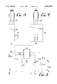
- FIG. 5 is a perspective elevation view of another embodiment of the battery charger of the present invention.
- FIG. 6 is a side elevation view of the battery charger of FIG. 5;
- FIG. 7 is a bottom elevation view of the battery charger of FIG. 5;
- FIG. 8 is an embodiment of a direct current converter circuit utilized in the battery charger of the present invention.
- FIG. 9 is a block circuit diagram of an embodiment of an alternating current converter circuit utilized in the battery charger of the present invention.
- FIG. 10 is a block diagram of another embodiment of the battery charger of the present invention.
- FIG. 11 is a perspective view of the battery charger according to the present invention, with the direct current adaptor pivotably connected to the battery charger housing.
- the battery charger 10 comprises: (a) a first set of input terminals 12 for electrical connection to a direct current power source at a first voltage; (b) a second set of input terminals 14 for electrical connection to an alternating current power source at a second voltage; (c) a set of output terminals 16 for electrical connection to the power input terminals of the rechargeable battery; (d) a first converter circuit 18 electrically connected between the first set of input terminals 12 and the output terminals 16 of the battery charger 10 for converting a direct current at the first voltage to a direct current at a third voltage suitable for charging the battery; and (e) a second converter circuit 20 electrically connected between the second set of input terminals 14 and the first set of input terminals 12 of the battery charger 10 for converting an alternating current at the second voltage to a direct current at the first voltage.
- the first converter circuit 18 and the second converter circuit 20 are
- the battery charger 10 preferably further comprises a shell 22 for housing the components of the battery charger 10 discussed above.
- the battery charger 10 further comprises an alternating current adapter 24 for interfacing the battery charger 10 to an alternating current power outlet, wherein the adapter 24 is electrically connected to the second set of input terminals 14.
- the alternating current adapter 24 comprises two prongs 26 for interface with a residential power outlet unit.
- a NEMA 5-15P plug standard 125VAC, 10A can be utilized.
- the battery charger 10 further comprises a direct current adapter 28 for interfacing the battery charger 10 to a direct current power outlet, wherein the adapter 28 is electrically connected to the first set of input terminals 12.
- the direct current adapter 28 comprises an apparatus for interface with an automobile cigarette-lighter receptacle.
- a cigarette lighter adapter (1215VDC, 15a) can be utilized.
- the alternating current adapter 24 and the direct current adapter 28 are externally attached to the shell 22 and are electrically connected to the first converter circuit 18 and the second converter circuit 20 through the shell 22, respectively.
- the battery charger 10 of the present invention can be plugged into an automobile's cigarette-lighter housing for recharging batteries while traveling, and can also be plugged into wall power outlet units to recharge batteries using alternating current.
- the alternating current adapter 24 comprises two prongs 26 slidably disposed in the shell 22. To plug the battery charger 10 into a wall power outlet unit, the prongs are exposed by sliding them out of the shell 22. Sliding prongs are readily available from many manufacturers.
- the alternating current adapter 24 comprises a set of prongs 26 rotatably attached to the shell 22. Rotating prongs are readily available from many manufacturers. To plug the battery charger 10 into a wall power outlet unit, the prongs 26 are rotated away from the shell 22 to expose the prongs.
- the embodiment of the battery charger 10 shown in FIGS. 5-7 is the same as the embodiment of the battery charger 10 shown in FIGS. 2-4.
- the circuit comprises a pair of input terminals 30 for connection to a direct current power source, and a pair of output terminals 32 for providing a direct current for charging a battery.
- the circuit further comprises resistors R1, R2 (3.6K), and Rsc (0.33); capacitors Co (470 ⁇ F LYTIC), C5 (100 ⁇ F 25 V POLARIZED LYTIC), and CT2 (470 PF FILM); transformer L3 (220 ⁇ H); zener diode D5 (1N5819); and integrated circuit U2 (MOTOROLA MC34063).
- the circuit components are electrically interconnected as shown in FIG. 8.
- the IC U2 is a monolithic control circuit including functions required for DC to DC converters.
- U2 includes an internal temperature compensated reference, comparator, controlled duty cycle oscillator with an active current limit circuit, driver and high current output switch.
- the oscillator in the IC U2 is composed of a current source and sink which charges and discharges the external timing capacitor CT2 between an upper and lower preset threshold.
- the typical charge and discharge currents are 35 ⁇ A and 200 ⁇ A respectively, yielding about a 1 to 6 ratio.
- the ramp-up period is 6 times longer than that of the ramp-down period.
- the upper threshold is equal to the internal reference voltage of 1.25 volts and the lower is approximately equal to 0.75 V.
- the oscillator runs continuously at a rate controlled by the selected value of the capacitor CT2.
- the first converter circuit 18 utilizes a step-down converter.
- the inductor L3 is switched across the input voltage through an internal switch within the integrated circuit U2. When the switch is turned off, the inductor L3 discharges to the output capacitor C 0 .
- a regulated DC output voltage is obtained across the capacitor C 0 and is controlled by varying the on time of the switch.
- the capacitor CT2 is used to set the on time of the switch.
- the capacitor C5 is the input filter capacitor and is rated for about 35 V DC.
- the resistors R1 and R2 are used to set the output voltage value.
- the resistor R SC is used to set the maximum output current value.
- the switch in the IC U2 interrupts the input voltage and provides a variable duty cycle squarewave to a simple LC filter formed by L3 and C 0 .
- the filter averages the squarewaves producing a dc output voltage that can be set to any level less than the input by controlling the percent conduction time of the switch to that of the total switching cycle time.
- the IC U2 achieves regulation by varying the on-time (T on ) and the total switching cycle time.
- T on the on-time
- the inductor L3 current IL3 is zero, and the output voltage Vout is at its nominal value.
- the output voltage across capacitor C 0 will eventually decay below nominal because it is the only component supply current into the external load. This voltage deficiency is monitored by the switching control circuit and causes it to drive the switch into saturation.
- the voltage across the inductor is equal to Vin-Vsat-Vout and the peak current at any instant is:
- the converter circuit comprises a pair of input terminals 34 for electrical connection to an AC power source, and a pair of output terminals 36 for providing direct current to the first converter circuit 18 as shown in FIG. 1.
- the second converter circuit 20 further comprises resistors Ron (330K 400 V), Roff (150K), and Rs (2M); capacitors C1 (0.15 ⁇ F FILM), C2 (22 ⁇ F 35 V LYTIC), C3 (1 ⁇ F POLARIZED LYTIC), C4 (2.2 ⁇ F 450 V POLARIZED LYTIC), CT1 (150 PF FILM); diodes D1 (1N4937), D2 (1N4937), D3 (1N4935), D4 (1N4006); inductors L1 (1 mH 400 V), L2 (70 ⁇ H); MOSFET transistor Q1; fuse F1 (0.25 A FUSE); and integrated circuit U1 (MOTOROLA UCC3889).
- the circuit components are electrically interconnected as shown in FIG. 9. All of the circuit components for the first converter circuit 18 are readily available as recognized by practitioners in the art.
- the converter circuit converts an input alternating current at the second voltage ranging from about 80 volts to about 265 volts to a direct current at the first voltage of about 12 volts.
- the converter circuit utilizes a cascaded Flyback Converter operated in the discontinuous current mode. Two Flyback stages in series are used to perform voltage transformation.
- the first Flyback stage includes the inductor L1 which is switched across the input voltage when the MOSFET Q1 turns on. Energy stored is in inductor L1 as current rises linearly, until the MOSFET Q1 is turned off. The inductor L1 then discharges into the capacitor C1 with the diode D1 conducting. In steady state operation, the switching action of the MOSFET Q1 develops a net direct current voltage across the capacitor C1, which is the output capacitor of the first Flyback Converter stage.
- the second Flyback Converter stage includes the inductor L2 which is switched across the capacitor C1 while the MOSFET Q1 is on.
- the voltage across the inductor L2 is negative with respect to ground, and energy is stored in the inductor L2 as the current rises linearly.
- the MOSFET Q1 is turned off, the inductor L2 discharges into the capacitor C2.
- a regulated direct current output voltage is obtained across the capacitor C2 which can be controlled by varying the on-time of the MOSFET Q1.
- the capacitor C3 maintains the voltage supply for the integrated circuit U1 within the integrated circuit U1's UVLO hysteresis region when the second Flyback Converter begins operation.
- the capacitor C4 is a bulk input capacitor and is rated at or above 450 VCD, and the diodes D1 through D4 are 800 volt type diodes.
- diode switching speed is not critical. However, the diodes should have recovery times at or below 0.25 ms.
- standard 1N4937 type 600 volt diodes can be used in high-voltage switching, and lower-voltage 1N4935 diodes can be used as output diodes.
- the timing capacitor CT1, and resistors Ron and Roff are used to set the operating frequency value of the circuit.
- the resistor R1 is rated for about 400 volts.
- the resistor Rs is connected in parallel with the timing capacitor CT1 and is used to discharge the capacitor CT1 when the converter output voltage goes to 0.
- the placement of the resistor Rs also sets the maximum OFF-time of the MOSFET Q1 and only is used to program the minimum frequency for start-up phase of the converter and for short-circuit protection.
- the battery charger 10 includes: (a) a set of AC input terminals 38, (b) a set of DC input terminals 40, (c) a set of output terminals 42, (d) an AC to DC converter 44 electrically connected between the AC input terminals 38 and the output terminals 42, and (e) a DC to DC converter 46 electrically connected between the DC input terminals 40 and the output terminals 42.
- the AC to DC converter 44 converts an AC voltage in the range of about 80-265 volts to a direct current voltage of about 12 volts suitable for charging batteries.
- the DC to DC converter 46 converts a DC voltage of about 25 volts to a DC output voltage of about 12 volts.
- the circuit diagrams for the AC to DC and DC to DC converters illustrated in FIGS. 8 and 9, respectively, can be utilized for the AC converter 44 and DC converter 46 of the embodiment of the battery charger 10 shown in FIG. 10.
- the battery charger 10 can further comprise: (a) an AC adapter 24 electrically connected to the AC input terminals 38, (b) a DC adapter 28 electrically connected to the DC input terminals 40, and a (c) housing 22, all as described above.
- the direct current adaptor 28 is connected to the shell 22 for housing the battery charger circuit by a pivot mechanism 48.
- the direct current adapter 28 is rotatable about the pivot within an arc angle, such as 180°.
- the pivot mechanism 48 allows the direct current adapter 28 to be plugged into an automobile cigarette receptacle without obstruction by the housing 22, and also allows for compact storage of the battery charger by folding the direct current adapter 28 adjacent the housing 22 when the battery charger is not in use.
- a user inserts the direct current adapter 28 into the car's cigarette receptacle.
- the battery charger 10 can charge a battery in approximately four to five hours.
- the user inserts the alternating current adapter prongs 26 directly into a wall power outlet receptacle.
- the battery charger 10 charges a cellular phone battery described above in approximately eight to ten hours.
- the battery charger 10 utilizes the phone's data port or a charge port to eliminate the need for a bulky desktop housing to hold the phone.
- the dimensions for the housing do not exceed 3" ⁇ 1" ⁇ 2" (L ⁇ H ⁇ W).
- the above embodiments of the invention are only a few possible examples of the battery charger 10 of the present invention. It needs to be understood that the present invention is not limited to operation in accordance with the embodiments discussed in this description, and that one skilled in the art would readily understand how to modify the invention as disclosed to obtain equivalent results without departing from the spirit and scope of the present invention.
- the sliding or rotating AC prongs for the AC adapter can be replaced by a power cord attached to a plug for interface with wall outlet units.
Abstract
Description
Vout=Vin(% T.sub.on)=Vin(T.sub.on /T.sub.on +T.sub.off)
IL=(Vin-Vsat-Vout/L)t
Claims (13)
Priority Applications (2)
| Application Number | Priority Date | Filing Date | Title |
|---|---|---|---|
| US08/802,721 US5847545A (en) | 1996-02-20 | 1997-02-20 | Dual A/C and D/C input powered portable battery charger |
| GB9718924A GB2322486B (en) | 1997-02-20 | 1997-09-05 | Improvements in or relating to a battery charger |
Applications Claiming Priority (2)
| Application Number | Priority Date | Filing Date | Title |
|---|---|---|---|
| US60363496A | 1996-02-20 | 1996-02-20 | |
| US08/802,721 US5847545A (en) | 1996-02-20 | 1997-02-20 | Dual A/C and D/C input powered portable battery charger |
Related Parent Applications (1)
| Application Number | Title | Priority Date | Filing Date |
|---|---|---|---|
| US60363496A Continuation-In-Part | 1996-02-20 | 1996-02-20 |
Publications (1)
| Publication Number | Publication Date |
|---|---|
| US5847545A true US5847545A (en) | 1998-12-08 |
Family
ID=25184514
Family Applications (1)
| Application Number | Title | Priority Date | Filing Date |
|---|---|---|---|
| US08/802,721 Expired - Lifetime US5847545A (en) | 1996-02-20 | 1997-02-20 | Dual A/C and D/C input powered portable battery charger |
Country Status (2)
| Country | Link |
|---|---|
| US (1) | US5847545A (en) |
| GB (1) | GB2322486B (en) |
Cited By (87)
| Publication number | Priority date | Publication date | Assignee | Title |
|---|---|---|---|---|
| US5982149A (en) * | 1998-11-26 | 1999-11-09 | Shih; Hung-Ming | Device of a micro mobile phone battery charger |
| US6127803A (en) * | 1999-04-12 | 2000-10-03 | Ceramate Technical Co., Ltd. | Multi-purpose electric charging apparatus |
| US6134125A (en) * | 1999-05-17 | 2000-10-17 | Stmicroelectronics, Inc. | AC and DC input power supply |
| US6362987B1 (en) | 2000-12-27 | 2002-03-26 | John Yurek | Wall mounted electrical outlet receptacle for providing low voltage DC current |
| KR20020067997A (en) * | 2002-05-27 | 2002-08-24 | 다마전자 주식회사 | Apparatus for charging power in mobile terminal |
| US6478628B1 (en) * | 1998-04-21 | 2002-11-12 | Teco Industries Company Limited | Cigarette lighter socket adapter with improved contact, dual sockets, and/or movable plug |
| US6483273B1 (en) * | 2001-02-21 | 2002-11-19 | Conwave, Inc. | AC-powered recharging device for cigarette lighter-adapted rechargeable appliances |
| US6510067B1 (en) * | 2000-11-03 | 2003-01-21 | Cisco Technology, Inc. | System, method and apparatus for protecting consumer electronic devices from brownouts and short duration power outages |
| WO2003026377A2 (en) * | 2001-09-28 | 2003-04-03 | Phosphor Electronics Co. Ltd. | Ac/dc charger for mobile phone |
| WO2003041189A2 (en) * | 2001-11-09 | 2003-05-15 | France Telecom | Method and device for supplying electric power to an appliance |
| WO2003055047A2 (en) * | 2001-12-05 | 2003-07-03 | Montante Charles J | Dual input voltage adapter system and method |
| US20030193476A1 (en) * | 2002-04-11 | 2003-10-16 | Ho-Lung Lu | Structure of rechargeable wireless mouse |
| US20030218445A1 (en) * | 2002-05-21 | 2003-11-27 | Behar Brad M. | Portable electronic device carrier and charger |
| US20030230934A1 (en) * | 2002-06-17 | 2003-12-18 | Cordelli Gary Gerard | Modular power supply with multiple and interchangeable output units for AC- and DC-powered equipment |
| US6751482B1 (en) * | 1997-06-19 | 2004-06-15 | Byard G. Nilsson | Wireless mobile telephone system with alternative power instruments and DTMF Capability |
| US6767256B1 (en) | 2003-03-12 | 2004-07-27 | Motorola, Inc. | Cigarette lighted adaptor with mechanical stepper joint |
| US6781249B2 (en) * | 2001-08-29 | 2004-08-24 | Hewlett-Packard Development Company, L.P. | Retrofittable power supply |
| US20040164704A1 (en) * | 2003-02-24 | 2004-08-26 | Tai-Her Yang | Integrated charger with multi-form input sources |
| US20050110455A1 (en) * | 2003-11-05 | 2005-05-26 | Fu-I Yang | Integrated charger for use in a car |
| FR2865321A1 (en) * | 2004-01-20 | 2005-07-22 | Cie Du Cap | Battery charging device for scooter or motorcycle, has electronic interface controlling and adapting current or voltage provided by battery of motor vehicle or charged battery of scooter or motorcycle, to battery to be charged |
| US6923686B1 (en) * | 2004-03-19 | 2005-08-02 | Lucent Trans Electronic Co. Ltd. | Rotatable onboard mobile phone charger |
| US6956353B1 (en) * | 2002-10-11 | 2005-10-18 | Orrin Edward Klitzner | Universal battery charger for cellular telephones and other battery operated devices |
| US6994592B1 (en) | 2004-08-27 | 2006-02-07 | Hop-On Wireless, Inc. | Universal charging apparatus |
| US7035126B1 (en) * | 2002-06-10 | 2006-04-25 | Comarco Wireless Technologies, Inc. | Programmable power supply capable of receiving AC and DC power input |
| US20060262580A1 (en) * | 2005-12-14 | 2006-11-23 | Jeng-Fuh Liu | Adapter and method of detecting and adjusting voltages and currents |
| US20060276236A1 (en) * | 2005-04-01 | 2006-12-07 | Vector Products, Inc. | Cigarette lighter adapter device that interfaces with an external device via a port interface |
| US7189473B2 (en) | 2003-06-03 | 2007-03-13 | Eastway Fair Company Limited | Battery venting system |
| US20070080663A1 (en) * | 2005-10-11 | 2007-04-12 | Jeff Obering | Portable charger with a rechargeable back-up battery |
| CN1312822C (en) * | 2002-08-23 | 2007-04-25 | 宇东电浆科技股份有限公司 | Battery charger capable of switching several power supplies |
| US20070091656A1 (en) * | 2005-10-13 | 2007-04-26 | Amir Navid | Power adapter |
| US7212420B2 (en) * | 2002-02-12 | 2007-05-01 | Sheng Hsin Liao | Universal serial bus voltage transformer |
| US20070126290A1 (en) * | 2005-11-01 | 2007-06-07 | Jaynes Stephen R | Systems and methods for powering an electronic device from selectable power sources |
| US20070170785A1 (en) * | 2006-01-26 | 2007-07-26 | Mccoy Bryan W | AC/DC converter having single detectable input |
| US20070182628A1 (en) * | 2006-01-19 | 2007-08-09 | Scott Pomerantz | Satellite-positioning-system tracking device and method for determining a position of the same |
| US20070202724A1 (en) * | 2006-02-24 | 2007-08-30 | Credo Technology Corporation | Isolated dual AC-DC plug |
| EP1845590A1 (en) * | 2006-04-11 | 2007-10-17 | Modern Sense Ltd | Universal battery charger and/or power adaptor |
| US20080048613A1 (en) * | 2006-08-09 | 2008-02-28 | Honeywell International Inc. | Voltage regulator in a battery block |
| US20080137386A1 (en) * | 2006-12-06 | 2008-06-12 | Det International Holding Limited | Portable power supply apparatus capable of receiving ac or dc input power |
| US20080150480A1 (en) * | 2006-10-13 | 2008-06-26 | Amir Navid | Video game controller charging system |
| US20080157715A1 (en) * | 2006-01-07 | 2008-07-03 | Egate-International Gmbh | Plug-type charger for small electrical device |
| US20080211310A1 (en) * | 2006-12-06 | 2008-09-04 | Det International Holding Limited | Portable power supply apparatus capable of receiving ac or dc input power |
| US20080258642A1 (en) * | 2007-04-20 | 2008-10-23 | Bharat Patel | Lamp base with electrical device recharging receptacle and method |
| US20090026843A1 (en) * | 2005-11-16 | 2009-01-29 | Dae-Young Youn | Portable apparatus of emergency power supply and battery charger |
| US20090045774A1 (en) * | 2007-08-13 | 2009-02-19 | Technuity, Inc. | Multiple interfaces for a rechargeable battery pack |
| US7556203B2 (en) | 2005-06-27 | 2009-07-07 | Hand Held Products, Inc. | Method and system for linking a wireless hand held optical reader with a base unit or other wireless device |
| US20090309542A1 (en) * | 2008-06-17 | 2009-12-17 | Huang-Chiang Hung | Multi-input charger |
| US20090315513A1 (en) * | 2008-06-20 | 2009-12-24 | Superior Communications | Vehicle power charger |
| US7686216B2 (en) | 2006-06-13 | 2010-03-30 | Hand Held Products, Inc. | Method and apparatus for uniquely associating a bar code reading terminal to a cash register in a retail store network |
| US20100127669A1 (en) * | 2007-06-11 | 2010-05-27 | Toyota Jidosha Kabushiki Kaisha | Control device and control method for electric system |
| US7741809B2 (en) | 2006-01-06 | 2010-06-22 | Milwaukee Electric Tool Corporation | Electrical component including a battery receptacle for including a battery |
| US7835534B2 (en) | 2003-10-14 | 2010-11-16 | Robert Bosch Gmbh | Battery charging jobsite lunchbox |
| US7868590B2 (en) | 2001-11-09 | 2011-01-11 | Milwaukee Electric Tool Corporation | Electrical component, such as a radio, MP3 player, audio component, battery charger, radio/charger, MP3 player/radio, MP3 player/charger or MP3 player/radio/charger, having a selectively connectable battery charger |
| US20110095728A1 (en) * | 2009-10-28 | 2011-04-28 | Superior Communications, Inc. | Method and apparatus for recharging batteries in a more efficient manner |
| US8213204B2 (en) * | 2009-04-01 | 2012-07-03 | Comarco Wireless Technologies, Inc. | Modular power adapter |
| US20120275206A1 (en) * | 2001-10-22 | 2012-11-01 | Apple Inc. | Power adapters for powering and/or charging peripheral devices |
| US20130082533A1 (en) * | 2009-11-20 | 2013-04-04 | Freescale Semiconductor, Inc. | Systems and methods for delivering power in response to a connection event |
| US20130150134A1 (en) * | 2011-10-06 | 2013-06-13 | Anthem Grand Llc | Smart Phone and/or Consumer Electronics Device Charger System |
| US20130171879A1 (en) * | 2011-12-30 | 2013-07-04 | Hon Hai Precision Industry Co., Ltd. | Charger with removable cap |
| ITMI20120176A1 (en) * | 2012-02-08 | 2013-08-09 | F & B Internat S R L | POWER SUPPLY |
| US8604752B2 (en) | 2003-10-14 | 2013-12-10 | Robert Bosch Gmbh | Portable battery charging and audio unit |
| US20130328526A1 (en) * | 2012-06-07 | 2013-12-12 | Navajo Manufacturing Company, Inc. | Compact car charger |
| US20140152257A1 (en) * | 2012-12-03 | 2014-06-05 | Garold C. Miller | Compact portable battery charger |
| US20140192456A1 (en) * | 2012-02-01 | 2014-07-10 | Dell Products L.P. | Systems and methods for coupling ac power to a rack-level power infrastructure |
| US20150028797A1 (en) * | 2013-03-20 | 2015-01-29 | Garold C. Miller | Portable Power Charger with Power Input and Power Output Connection Interfaces |
| US20150130403A1 (en) * | 2013-11-13 | 2015-05-14 | Google Technology Holdings LLC | Battery-charging device and method of manufacturing same |
| WO2015157857A1 (en) * | 2014-04-14 | 2015-10-22 | Siemens Canada Limited | Power supply circuit with active under-voltage protection |
| USD758965S1 (en) * | 2015-02-03 | 2016-06-14 | Jerry Jen | Charging adapter |
| US20160211682A1 (en) * | 2009-11-19 | 2016-07-21 | Tseng-Lu Chien | Plug-In AC Outlet Electric Device Has Replaceable Rechargeable Battery |
| US9413179B2 (en) * | 2013-07-09 | 2016-08-09 | Yeoshua Sorias | Detachably integrated battery charger for mobile cell phones and like devices |
| CN105897007A (en) * | 2016-04-16 | 2016-08-24 | 合肥博雷电气有限公司 | Large power microwave device testing power supply |
| USD787440S1 (en) * | 2014-12-11 | 2017-05-23 | Christopher Pignotti | Combination USB charger |
| US9692247B2 (en) * | 2009-03-09 | 2017-06-27 | Advanced Wireless Innovations Llc | Apparatus and method for powering a mobile device |
| US9715607B2 (en) | 2010-02-11 | 2017-07-25 | Advanced Wireless Innovations Llc | Apparatus and methods for communicating power and data with electronic devices |
| US9866044B1 (en) * | 2015-12-08 | 2018-01-09 | Paulette Bell | Combined vehicle and standard electrical outlet charger |
| US9893543B2 (en) | 2011-08-10 | 2018-02-13 | Halo2Cloud, LLC | Portable power charger |
| US9899850B2 (en) | 2014-08-29 | 2018-02-20 | Flextronics Ap, Llc | Vehicle based portable charging device |
| CN108110851A (en) * | 2018-01-12 | 2018-06-01 | 武汉中电通信有限责任公司 | A kind of intelligent charger |
| USD823800S1 (en) * | 2017-03-08 | 2018-07-24 | Mathew Inskeep | Inverter |
| US20190013686A1 (en) * | 2017-07-07 | 2019-01-10 | EcoFlow Technology Limited | Mobile power source |
| US10236706B2 (en) | 2009-07-12 | 2019-03-19 | Advanced Wireless Innovations Llc | Configurable apparatus and methods for supplying power and data to electronic devices |
| DE102017122241A1 (en) * | 2017-09-26 | 2019-03-28 | Hans-Peter Wilfer | plug connector |
| USD845243S1 (en) | 2017-10-02 | 2019-04-09 | Google Llc | Plug |
| USD873212S1 (en) * | 2017-03-14 | 2020-01-21 | Philip Morris Products S.A. | Charging unit |
| US10855086B2 (en) | 2004-01-15 | 2020-12-01 | Comarco Wireless Systems Llc | Power supply equipment utilizing interchangeable tips to provide power and a data signal to electronic devices |
| USD913948S1 (en) | 2019-05-09 | 2021-03-23 | Halo International Sezc, Ltd. | Portable charger |
| US11473741B2 (en) | 2007-05-31 | 2022-10-18 | Aaron Chien | LED light has built-in air related part(s) |
| US11552485B2 (en) | 2019-01-08 | 2023-01-10 | Bollinger Industries, Inc. | Fold-flat car charger interface |
Families Citing this family (6)
| Publication number | Priority date | Publication date | Assignee | Title |
|---|---|---|---|---|
| GB2346268B (en) * | 1999-01-18 | 2002-12-11 | Mark Loughborough | Power supplies |
| US20020000789A1 (en) * | 2000-04-21 | 2002-01-03 | Haba Chaz G | Charger assembly |
| US7072200B2 (en) | 2002-06-10 | 2006-07-04 | Comarco Wireless Technologies, Inc. | Cradle for receiving an adapter |
| US7402986B2 (en) | 2004-07-26 | 2008-07-22 | Wolfson Microelectronics Plc | Power supply circuit for portable battery powered device |
| GB2416605A (en) * | 2004-07-26 | 2006-02-01 | Wolfson Ltd | Dual power bus for battery powered device |
| EP1737099B1 (en) | 2005-06-20 | 2015-03-11 | BlackBerry Limited | Power management systems and methods for a mobile device |
Citations (11)
| Publication number | Priority date | Publication date | Assignee | Title |
|---|---|---|---|---|
| DE823052C (en) * | 1950-01-28 | 1951-12-06 | Dixma Ab | Axle coupling that can be engaged and disengaged |
| US4160941A (en) * | 1977-12-01 | 1979-07-10 | American Safety Equipment Corporation | Multi-purpose battery charger |
| EP0038376A2 (en) * | 1980-04-21 | 1981-10-28 | Elmar H. Will | Battery operated electric handtool |
| WO1982004355A1 (en) * | 1981-05-29 | 1982-12-09 | Peter Frederick Barker | Rechargeable battery system |
| US4922178A (en) * | 1987-08-31 | 1990-05-01 | Motorola, Inc. | Dual source rechargeable battery |
| EP0510300A2 (en) * | 1991-04-25 | 1992-10-28 | ERICH JÄGER GmbH & Co. KG | Pocket lamp |
| US5160879A (en) * | 1991-10-08 | 1992-11-03 | Curtis Manufacturing Company, Inc. | Safe, rechargeable, battery-containing power pack and method |
| US5414610A (en) * | 1993-06-21 | 1995-05-09 | Ast Research, Inc. | Universal power converter with single, shared power transformation circuit |
| US5499187A (en) * | 1995-04-03 | 1996-03-12 | Arinc Research Corporation | Voltage sensing, autoselecting aircraft power supply interface |
| US5510691A (en) * | 1994-04-13 | 1996-04-23 | Xtend Micro Products, Inc | Modular power supply and modular interconnect system for portable electronic equipment |
| US5610497A (en) * | 1994-12-01 | 1997-03-11 | Ericsson Inc. | Method and apparatus for providing continuous power to a battery powered device during battery transfer |
Family Cites Families (1)
| Publication number | Priority date | Publication date | Assignee | Title |
|---|---|---|---|---|
| GB823052A (en) * | 1955-10-15 | 1959-11-04 | Waldemar Witte | Improvements in or relating to pocket lamps or the like low current utilization devices |
-
1997
- 1997-02-20 US US08/802,721 patent/US5847545A/en not_active Expired - Lifetime
- 1997-09-05 GB GB9718924A patent/GB2322486B/en not_active Expired - Fee Related
Patent Citations (12)
| Publication number | Priority date | Publication date | Assignee | Title |
|---|---|---|---|---|
| DE823052C (en) * | 1950-01-28 | 1951-12-06 | Dixma Ab | Axle coupling that can be engaged and disengaged |
| US4160941A (en) * | 1977-12-01 | 1979-07-10 | American Safety Equipment Corporation | Multi-purpose battery charger |
| EP0038376A2 (en) * | 1980-04-21 | 1981-10-28 | Elmar H. Will | Battery operated electric handtool |
| US4514790A (en) * | 1980-04-21 | 1985-04-30 | Elmar Will | Rechargeable power pack and a pocket lamp for use therewith |
| WO1982004355A1 (en) * | 1981-05-29 | 1982-12-09 | Peter Frederick Barker | Rechargeable battery system |
| US4922178A (en) * | 1987-08-31 | 1990-05-01 | Motorola, Inc. | Dual source rechargeable battery |
| EP0510300A2 (en) * | 1991-04-25 | 1992-10-28 | ERICH JÄGER GmbH & Co. KG | Pocket lamp |
| US5160879A (en) * | 1991-10-08 | 1992-11-03 | Curtis Manufacturing Company, Inc. | Safe, rechargeable, battery-containing power pack and method |
| US5414610A (en) * | 1993-06-21 | 1995-05-09 | Ast Research, Inc. | Universal power converter with single, shared power transformation circuit |
| US5510691A (en) * | 1994-04-13 | 1996-04-23 | Xtend Micro Products, Inc | Modular power supply and modular interconnect system for portable electronic equipment |
| US5610497A (en) * | 1994-12-01 | 1997-03-11 | Ericsson Inc. | Method and apparatus for providing continuous power to a battery powered device during battery transfer |
| US5499187A (en) * | 1995-04-03 | 1996-03-12 | Arinc Research Corporation | Voltage sensing, autoselecting aircraft power supply interface |
Cited By (139)
| Publication number | Priority date | Publication date | Assignee | Title |
|---|---|---|---|---|
| US6751482B1 (en) * | 1997-06-19 | 2004-06-15 | Byard G. Nilsson | Wireless mobile telephone system with alternative power instruments and DTMF Capability |
| US6478628B1 (en) * | 1998-04-21 | 2002-11-12 | Teco Industries Company Limited | Cigarette lighter socket adapter with improved contact, dual sockets, and/or movable plug |
| US5982149A (en) * | 1998-11-26 | 1999-11-09 | Shih; Hung-Ming | Device of a micro mobile phone battery charger |
| US6127803A (en) * | 1999-04-12 | 2000-10-03 | Ceramate Technical Co., Ltd. | Multi-purpose electric charging apparatus |
| US6134125A (en) * | 1999-05-17 | 2000-10-17 | Stmicroelectronics, Inc. | AC and DC input power supply |
| US6510067B1 (en) * | 2000-11-03 | 2003-01-21 | Cisco Technology, Inc. | System, method and apparatus for protecting consumer electronic devices from brownouts and short duration power outages |
| US6362987B1 (en) | 2000-12-27 | 2002-03-26 | John Yurek | Wall mounted electrical outlet receptacle for providing low voltage DC current |
| US6483273B1 (en) * | 2001-02-21 | 2002-11-19 | Conwave, Inc. | AC-powered recharging device for cigarette lighter-adapted rechargeable appliances |
| US6781249B2 (en) * | 2001-08-29 | 2004-08-24 | Hewlett-Packard Development Company, L.P. | Retrofittable power supply |
| WO2003026377A2 (en) * | 2001-09-28 | 2003-04-03 | Phosphor Electronics Co. Ltd. | Ac/dc charger for mobile phone |
| KR20030027345A (en) * | 2001-09-28 | 2003-04-07 | (주)포스퍼전자 | A cellular phone charger using altering current and direct current |
| WO2003026377A3 (en) * | 2001-09-28 | 2003-11-20 | Phosphor Electronics Co Ltd | Ac/dc charger for mobile phone |
| US20120275206A1 (en) * | 2001-10-22 | 2012-11-01 | Apple Inc. | Power adapters for powering and/or charging peripheral devices |
| US8674558B2 (en) * | 2001-10-22 | 2014-03-18 | Apple Inc. | Power adapters for powering and/or charging peripheral devices |
| US10312704B2 (en) | 2001-10-22 | 2019-06-04 | Apple Inc. | Power adapters for powering and/or charging peripheral devices |
| WO2003041189A2 (en) * | 2001-11-09 | 2003-05-15 | France Telecom | Method and device for supplying electric power to an appliance |
| US7868590B2 (en) | 2001-11-09 | 2011-01-11 | Milwaukee Electric Tool Corporation | Electrical component, such as a radio, MP3 player, audio component, battery charger, radio/charger, MP3 player/radio, MP3 player/charger or MP3 player/radio/charger, having a selectively connectable battery charger |
| US8203307B2 (en) | 2001-11-09 | 2012-06-19 | Milwaukee Electric Tool Corporation | Audio and charging system with audio device, power tool battery, and external battery charger |
| WO2003041189A3 (en) * | 2001-11-09 | 2004-03-04 | France Telecom | Method and device for supplying electric power to an appliance |
| US20030197425A1 (en) * | 2001-12-05 | 2003-10-23 | Montante Charles J. | Dual input voltage adapter system and method |
| WO2003055047A3 (en) * | 2001-12-05 | 2003-08-07 | Charles J Montante | Dual input voltage adapter system and method |
| WO2003055047A2 (en) * | 2001-12-05 | 2003-07-03 | Montante Charles J | Dual input voltage adapter system and method |
| US7212420B2 (en) * | 2002-02-12 | 2007-05-01 | Sheng Hsin Liao | Universal serial bus voltage transformer |
| US20030193476A1 (en) * | 2002-04-11 | 2003-10-16 | Ho-Lung Lu | Structure of rechargeable wireless mouse |
| US20030218445A1 (en) * | 2002-05-21 | 2003-11-27 | Behar Brad M. | Portable electronic device carrier and charger |
| KR20020067997A (en) * | 2002-05-27 | 2002-08-24 | 다마전자 주식회사 | Apparatus for charging power in mobile terminal |
| US7035126B1 (en) * | 2002-06-10 | 2006-04-25 | Comarco Wireless Technologies, Inc. | Programmable power supply capable of receiving AC and DC power input |
| US20030230934A1 (en) * | 2002-06-17 | 2003-12-18 | Cordelli Gary Gerard | Modular power supply with multiple and interchangeable output units for AC- and DC-powered equipment |
| CN1312822C (en) * | 2002-08-23 | 2007-04-25 | 宇东电浆科技股份有限公司 | Battery charger capable of switching several power supplies |
| US6956353B1 (en) * | 2002-10-11 | 2005-10-18 | Orrin Edward Klitzner | Universal battery charger for cellular telephones and other battery operated devices |
| US20040164704A1 (en) * | 2003-02-24 | 2004-08-26 | Tai-Her Yang | Integrated charger with multi-form input sources |
| US6767256B1 (en) | 2003-03-12 | 2004-07-27 | Motorola, Inc. | Cigarette lighted adaptor with mechanical stepper joint |
| US7189473B2 (en) | 2003-06-03 | 2007-03-13 | Eastway Fair Company Limited | Battery venting system |
| US8604752B2 (en) | 2003-10-14 | 2013-12-10 | Robert Bosch Gmbh | Portable battery charging and audio unit |
| US7835534B2 (en) | 2003-10-14 | 2010-11-16 | Robert Bosch Gmbh | Battery charging jobsite lunchbox |
| US20050110455A1 (en) * | 2003-11-05 | 2005-05-26 | Fu-I Yang | Integrated charger for use in a car |
| US11586233B2 (en) | 2004-01-15 | 2023-02-21 | Comarco Wireless Systems Llc | Power supply systems |
| US10855086B2 (en) | 2004-01-15 | 2020-12-01 | Comarco Wireless Systems Llc | Power supply equipment utilizing interchangeable tips to provide power and a data signal to electronic devices |
| US10855087B1 (en) | 2004-01-15 | 2020-12-01 | Comarco Wireless Systems Llc | Power supply systems |
| US10951042B2 (en) | 2004-01-15 | 2021-03-16 | Comarco Wireless Systems Llc | Power supply systems |
| FR2865321A1 (en) * | 2004-01-20 | 2005-07-22 | Cie Du Cap | Battery charging device for scooter or motorcycle, has electronic interface controlling and adapting current or voltage provided by battery of motor vehicle or charged battery of scooter or motorcycle, to battery to be charged |
| US6923686B1 (en) * | 2004-03-19 | 2005-08-02 | Lucent Trans Electronic Co. Ltd. | Rotatable onboard mobile phone charger |
| US20060046576A1 (en) * | 2004-08-27 | 2006-03-02 | Hop-On Wireless, Inc. | Universal charging apparatus |
| US6994592B1 (en) | 2004-08-27 | 2006-02-07 | Hop-On Wireless, Inc. | Universal charging apparatus |
| US20060276236A1 (en) * | 2005-04-01 | 2006-12-07 | Vector Products, Inc. | Cigarette lighter adapter device that interfaces with an external device via a port interface |
| US7338328B2 (en) * | 2005-04-01 | 2008-03-04 | The Black & Decker Corporation | Cigarette lighter adapter device that interfaces with an external device via a port interface |
| US7556203B2 (en) | 2005-06-27 | 2009-07-07 | Hand Held Products, Inc. | Method and system for linking a wireless hand held optical reader with a base unit or other wireless device |
| US20070080663A1 (en) * | 2005-10-11 | 2007-04-12 | Jeff Obering | Portable charger with a rechargeable back-up battery |
| US20070091656A1 (en) * | 2005-10-13 | 2007-04-26 | Amir Navid | Power adapter |
| US20070126290A1 (en) * | 2005-11-01 | 2007-06-07 | Jaynes Stephen R | Systems and methods for powering an electronic device from selectable power sources |
| US7859133B2 (en) * | 2005-11-16 | 2010-12-28 | Smart Power Solutions Inc. | Portable apparatus of emergency power supply and battery charger |
| US20090026843A1 (en) * | 2005-11-16 | 2009-01-29 | Dae-Young Youn | Portable apparatus of emergency power supply and battery charger |
| US20060262580A1 (en) * | 2005-12-14 | 2006-11-23 | Jeng-Fuh Liu | Adapter and method of detecting and adjusting voltages and currents |
| US7741809B2 (en) | 2006-01-06 | 2010-06-22 | Milwaukee Electric Tool Corporation | Electrical component including a battery receptacle for including a battery |
| US20080157715A1 (en) * | 2006-01-07 | 2008-07-03 | Egate-International Gmbh | Plug-type charger for small electrical device |
| US20070182628A1 (en) * | 2006-01-19 | 2007-08-09 | Scott Pomerantz | Satellite-positioning-system tracking device and method for determining a position of the same |
| US8022867B2 (en) * | 2006-01-19 | 2011-09-20 | Broadcom Corporation | Satellite-positioning-system tracking device and method for determining a position of the same |
| US20070170785A1 (en) * | 2006-01-26 | 2007-07-26 | Mccoy Bryan W | AC/DC converter having single detectable input |
| US7388305B2 (en) * | 2006-01-26 | 2008-06-17 | Mobility Electronics, Inc. | AC/DC converter having single detectable input |
| US20070202724A1 (en) * | 2006-02-24 | 2007-08-30 | Credo Technology Corporation | Isolated dual AC-DC plug |
| EP1999540A2 (en) * | 2006-02-24 | 2008-12-10 | Robert Bosch GmbH | Isolated dual ac-dc plug |
| US7438574B2 (en) | 2006-02-24 | 2008-10-21 | Robert Bosch Gmbh | Isolated dual AC-DC plug |
| EP1999540A4 (en) * | 2006-02-24 | 2011-11-16 | Bosch Gmbh Robert | Isolated dual ac-dc plug |
| EP1845590A1 (en) * | 2006-04-11 | 2007-10-17 | Modern Sense Ltd | Universal battery charger and/or power adaptor |
| US7686216B2 (en) | 2006-06-13 | 2010-03-30 | Hand Held Products, Inc. | Method and apparatus for uniquely associating a bar code reading terminal to a cash register in a retail store network |
| US20080048613A1 (en) * | 2006-08-09 | 2008-02-28 | Honeywell International Inc. | Voltage regulator in a battery block |
| US8143848B2 (en) | 2006-10-13 | 2012-03-27 | Nyko Technologies, Inc. | Video game controller charging system having a docking structure |
| US20080150480A1 (en) * | 2006-10-13 | 2008-06-26 | Amir Navid | Video game controller charging system |
| US8633675B2 (en) | 2006-10-13 | 2014-01-21 | Nyko Technologies, Inc. | Video game controller charging system having a docking structure |
| US9705344B2 (en) | 2006-10-13 | 2017-07-11 | Nyko Technologies, Inc. | Video game controller charging system having a docking structure |
| US8536832B2 (en) | 2006-10-13 | 2013-09-17 | Nyko Technologies, Inc. | Video game controller charging system having a docking structure |
| US9174121B2 (en) | 2006-10-13 | 2015-11-03 | Nyko Technologies, Inc. | Video game controller charging system having a docking structure |
| US8378630B2 (en) | 2006-10-13 | 2013-02-19 | Nyko Technologies, Inc. | Video game controller charging system having a docking structure |
| US20080137386A1 (en) * | 2006-12-06 | 2008-06-12 | Det International Holding Limited | Portable power supply apparatus capable of receiving ac or dc input power |
| US20080211310A1 (en) * | 2006-12-06 | 2008-09-04 | Det International Holding Limited | Portable power supply apparatus capable of receiving ac or dc input power |
| US7736033B2 (en) * | 2007-04-20 | 2010-06-15 | Bharat Patel | Lamp base with electrical device recharging receptacle and method |
| US20080258642A1 (en) * | 2007-04-20 | 2008-10-23 | Bharat Patel | Lamp base with electrical device recharging receptacle and method |
| US11473741B2 (en) | 2007-05-31 | 2022-10-18 | Aaron Chien | LED light has built-in air related part(s) |
| US20100127669A1 (en) * | 2007-06-11 | 2010-05-27 | Toyota Jidosha Kabushiki Kaisha | Control device and control method for electric system |
| US8183837B2 (en) * | 2007-06-11 | 2012-05-22 | Toyota Jidosha Kabushiki Kaisha | Control device and control method for electric system |
| US20090045774A1 (en) * | 2007-08-13 | 2009-02-19 | Technuity, Inc. | Multiple interfaces for a rechargeable battery pack |
| US7880431B2 (en) * | 2007-08-13 | 2011-02-01 | Technuity, Inc. | Multiple interfaces for a rechargeable battery pack |
| US20090309542A1 (en) * | 2008-06-17 | 2009-12-17 | Huang-Chiang Hung | Multi-input charger |
| US8446125B2 (en) | 2008-06-20 | 2013-05-21 | Superior Communications, Inc. | Vehicle power charger |
| US20090315513A1 (en) * | 2008-06-20 | 2009-12-24 | Superior Communications | Vehicle power charger |
| US9831703B2 (en) | 2009-03-09 | 2017-11-28 | Advanced Wireless Innovations Llc | Apparatus and method for communicating data and power with electronic devices |
| US9735604B2 (en) | 2009-03-09 | 2017-08-15 | Advanced Wireless Innovations Llc | Apparatus and method for communicating data and power with electronic devices |
| US9692247B2 (en) * | 2009-03-09 | 2017-06-27 | Advanced Wireless Innovations Llc | Apparatus and method for powering a mobile device |
| US8213204B2 (en) * | 2009-04-01 | 2012-07-03 | Comarco Wireless Technologies, Inc. | Modular power adapter |
| US10236706B2 (en) | 2009-07-12 | 2019-03-19 | Advanced Wireless Innovations Llc | Configurable apparatus and methods for supplying power and data to electronic devices |
| US8836282B2 (en) | 2009-10-28 | 2014-09-16 | Superior Communications, Inc. | Method and apparatus for recharging batteries in a more efficient manner |
| US8653789B2 (en) | 2009-10-28 | 2014-02-18 | Superior Communications, Inc. | Method and apparatus for recharging batteries in a more efficient manner |
| US20110095728A1 (en) * | 2009-10-28 | 2011-04-28 | Superior Communications, Inc. | Method and apparatus for recharging batteries in a more efficient manner |
| US20160211682A1 (en) * | 2009-11-19 | 2016-07-21 | Tseng-Lu Chien | Plug-In AC Outlet Electric Device Has Replaceable Rechargeable Battery |
| US20130082533A1 (en) * | 2009-11-20 | 2013-04-04 | Freescale Semiconductor, Inc. | Systems and methods for delivering power in response to a connection event |
| US9214807B2 (en) * | 2009-11-20 | 2015-12-15 | Freescale Semiconductor, Inc. | Systems and methods for delivering power in response to a connection event |
| US10664028B2 (en) | 2010-02-11 | 2020-05-26 | Advanced Wireless Innovations, Llc | Apparatus and methods for communicating power and data with electronic devices |
| US9715607B2 (en) | 2010-02-11 | 2017-07-25 | Advanced Wireless Innovations Llc | Apparatus and methods for communicating power and data with electronic devices |
| US9893543B2 (en) | 2011-08-10 | 2018-02-13 | Halo2Cloud, LLC | Portable power charger |
| US9130384B2 (en) * | 2011-10-06 | 2015-09-08 | Prong, Inc. | Smart phone and/or consumer electronics device charger system |
| US20130150134A1 (en) * | 2011-10-06 | 2013-06-13 | Anthem Grand Llc | Smart Phone and/or Consumer Electronics Device Charger System |
| US8784137B2 (en) * | 2011-12-30 | 2014-07-22 | Fu Tai Hua Industry (Shenzhen) Co., Ltd. | Charger with removable cap |
| US20130171879A1 (en) * | 2011-12-30 | 2013-07-04 | Hon Hai Precision Industry Co., Ltd. | Charger with removable cap |
| US20140192456A1 (en) * | 2012-02-01 | 2014-07-10 | Dell Products L.P. | Systems and methods for coupling ac power to a rack-level power infrastructure |
| US9661777B2 (en) | 2012-02-01 | 2017-05-23 | Dell Products L.P. | Systems and methods for coupling AC power to a rack-level power infrastructure |
| US9438012B2 (en) | 2012-02-01 | 2016-09-06 | Dell Products L.P. | Systems and methods for coupling AC power to a rack-level power infrastructure |
| US9172219B2 (en) * | 2012-02-01 | 2015-10-27 | Dell Products L.P. | Systems and methods for coupling AC power to a rack-level power infrastructure |
| ITMI20120176A1 (en) * | 2012-02-08 | 2013-08-09 | F & B Internat S R L | POWER SUPPLY |
| US20130328526A1 (en) * | 2012-06-07 | 2013-12-12 | Navajo Manufacturing Company, Inc. | Compact car charger |
| US8988040B2 (en) * | 2012-06-07 | 2015-03-24 | Navajo Manufacturing Company, Inc. | Compact car charger |
| US11005279B2 (en) * | 2012-12-03 | 2021-05-11 | Halo2Cloud, LLC | Compact portable battery charger |
| USD708131S1 (en) * | 2012-12-03 | 2014-07-01 | Halo2Cloud Llc | Portable power charger with retractable power input connectors |
| WO2014089006A1 (en) * | 2012-12-03 | 2014-06-12 | Halo2Cloud Llc | Compact portable battery charger |
| US20140152257A1 (en) * | 2012-12-03 | 2014-06-05 | Garold C. Miller | Compact portable battery charger |
| US10218213B2 (en) | 2013-03-20 | 2019-02-26 | Halo International SEZC Ltd. | Portable power charger with power input and power output connection interfaces |
| US10707694B2 (en) * | 2013-03-20 | 2020-07-07 | Halo International SEZC Ltd. | Portable power charger with power input and power output connection interfaces |
| US9793750B2 (en) * | 2013-03-20 | 2017-10-17 | Halo2Cloud Llc | Portable power charger with power input and power output connection interfaces |
| US20150028797A1 (en) * | 2013-03-20 | 2015-01-29 | Garold C. Miller | Portable Power Charger with Power Input and Power Output Connection Interfaces |
| US20190190307A1 (en) * | 2013-03-20 | 2019-06-20 | Halo International SEZC Ltd. | Portable power charger with power input and power output connection interfaces |
| US20160322858A1 (en) * | 2013-03-20 | 2016-11-03 | Halo2Cloud Llc | Portable power charger with power input and power output connection interfaces |
| US9385549B2 (en) * | 2013-03-20 | 2016-07-05 | Halo2Cloud, LLC. | Portable power charger with power input and power output connection interfaces |
| US9413179B2 (en) * | 2013-07-09 | 2016-08-09 | Yeoshua Sorias | Detachably integrated battery charger for mobile cell phones and like devices |
| US9318904B2 (en) * | 2013-11-13 | 2016-04-19 | Google Technology Holdings LLC | Battery-charging device and method of manufacturing same |
| US20150130403A1 (en) * | 2013-11-13 | 2015-05-14 | Google Technology Holdings LLC | Battery-charging device and method of manufacturing same |
| WO2015157857A1 (en) * | 2014-04-14 | 2015-10-22 | Siemens Canada Limited | Power supply circuit with active under-voltage protection |
| US9742187B2 (en) | 2014-04-14 | 2017-08-22 | Siemens Canada Limited | Power supply circuit with active under-voltage protection |
| US9899850B2 (en) | 2014-08-29 | 2018-02-20 | Flextronics Ap, Llc | Vehicle based portable charging device |
| USD787440S1 (en) * | 2014-12-11 | 2017-05-23 | Christopher Pignotti | Combination USB charger |
| USD758965S1 (en) * | 2015-02-03 | 2016-06-14 | Jerry Jen | Charging adapter |
| US9866044B1 (en) * | 2015-12-08 | 2018-01-09 | Paulette Bell | Combined vehicle and standard electrical outlet charger |
| CN105897007A (en) * | 2016-04-16 | 2016-08-24 | 合肥博雷电气有限公司 | Large power microwave device testing power supply |
| USD823800S1 (en) * | 2017-03-08 | 2018-07-24 | Mathew Inskeep | Inverter |
| USD873212S1 (en) * | 2017-03-14 | 2020-01-21 | Philip Morris Products S.A. | Charging unit |
| US20190013686A1 (en) * | 2017-07-07 | 2019-01-10 | EcoFlow Technology Limited | Mobile power source |
| DE102017122241A1 (en) * | 2017-09-26 | 2019-03-28 | Hans-Peter Wilfer | plug connector |
| USD845243S1 (en) | 2017-10-02 | 2019-04-09 | Google Llc | Plug |
| CN108110851A (en) * | 2018-01-12 | 2018-06-01 | 武汉中电通信有限责任公司 | A kind of intelligent charger |
| US11552485B2 (en) | 2019-01-08 | 2023-01-10 | Bollinger Industries, Inc. | Fold-flat car charger interface |
| USD913948S1 (en) | 2019-05-09 | 2021-03-23 | Halo International Sezc, Ltd. | Portable charger |
Also Published As
| Publication number | Publication date |
|---|---|
| GB2322486B (en) | 2001-07-25 |
| GB2322486A (en) | 1998-08-26 |
| GB9718924D0 (en) | 1997-11-12 |
Similar Documents
| Publication | Publication Date | Title |
|---|---|---|
| US5847545A (en) | Dual A/C and D/C input powered portable battery charger | |
| US5150032A (en) | Combined charging and supply circuit | |
| US7141954B2 (en) | Li-ion/Li-polymer battery charger configured to be DC-powered from multiple types of wall adapters | |
| US7560903B2 (en) | Apparatus and method for discharging electrical energy storage cells | |
| WO1995019654A1 (en) | Uninterruptible power supply | |
| JPH04340337A (en) | Uninterruptible power supply | |
| US20120268098A1 (en) | Power converter with hold up | |
| US6232749B1 (en) | Battery pack | |
| US20170229897A1 (en) | Devices and methods for portable energy storage | |
| US6044002A (en) | Flyback converter with limited output power | |
| EP1012898B1 (en) | Battery charger | |
| KR100405710B1 (en) | Electric automobile battery charging equipment | |
| EP3379685A1 (en) | Jump starter apparatus for recharging discharged battery of transportation means | |
| JP3040642U (en) | 2 power supply type battery charger | |
| US6353310B1 (en) | DC/DC charge and supply converting module | |
| GB2243961A (en) | DC-DC Power supply circuit | |
| CN100365906C (en) | DC-DC converting charging apparatus | |
| US11876458B2 (en) | Hybrid charger and inverter system | |
| US5973938A (en) | Switched-mode power supply | |
| CN1169600A (en) | Dual power battery charger | |
| WO2023048775A1 (en) | Hybrid charger and inverter system | |
| Cox | A universal power converter for emergency charging of electric vehicle batteries | |
| JP2002374668A (en) | Step-up dc-dc converter and portable terminal using the same | |
| Ballou | Power Supplies | |
| CN116352660A (en) | Electric tool |
Legal Events
| Date | Code | Title | Description |
|---|---|---|---|
| AS | Assignment |
Owner name: SYNAPSE PHARMACEUTICAL INTERNATIONAL, INC., CANADA Free format text: ASSIGNMENT OF ASSIGNORS INTEREST;ASSIGNOR:VINER, NORMAN M.;REEL/FRAME:008418/0622 Effective date: 19970221 |
|
| STCF | Information on status: patent grant |
Free format text: PATENTED CASE |
|
| FPAY | Fee payment |
Year of fee payment: 4 |
|
| REMI | Maintenance fee reminder mailed | ||
| FPAY | Fee payment |
Year of fee payment: 8 |
|
| FPAY | Fee payment |
Year of fee payment: 12 |
|
| AS | Assignment |
Owner name: BANK OF AMERICA, N.A., OREGON Free format text: SECURITY INTEREST;ASSIGNOR:SUPERIOR COMMUNICATIONS, INC.;REEL/FRAME:033791/0414 Effective date: 20140918 |