US5848485A - System for determining the position of a tool mounted on pivotable arm using a light source and reflectors - Google Patents
System for determining the position of a tool mounted on pivotable arm using a light source and reflectors Download PDFInfo
- Publication number
- US5848485A US5848485A US08/774,203 US77420396A US5848485A US 5848485 A US5848485 A US 5848485A US 77420396 A US77420396 A US 77420396A US 5848485 A US5848485 A US 5848485A
- Authority
- US
- United States
- Prior art keywords
- light
- reflectors
- transceiver
- arm
- machine
- Prior art date
- Legal status (The legal status is an assumption and is not a legal conclusion. Google has not performed a legal analysis and makes no representation as to the accuracy of the status listed.)
- Expired - Lifetime
Links
Images
Classifications
-
- E—FIXED CONSTRUCTIONS
- E02—HYDRAULIC ENGINEERING; FOUNDATIONS; SOIL SHIFTING
- E02F—DREDGING; SOIL-SHIFTING
- E02F3/00—Dredgers; Soil-shifting machines
- E02F3/04—Dredgers; Soil-shifting machines mechanically-driven
- E02F3/28—Dredgers; Soil-shifting machines mechanically-driven with digging tools mounted on a dipper- or bucket-arm, i.e. there is either one arm or a pair of arms, e.g. dippers, buckets
- E02F3/36—Component parts
- E02F3/42—Drives for dippers, buckets, dipper-arms or bucket-arms
- E02F3/43—Control of dipper or bucket position; Control of sequence of drive operations
- E02F3/435—Control of dipper or bucket position; Control of sequence of drive operations for dipper-arms, backhoes or the like
Definitions
- the present invention relates generally to a system used in controlling the operation of a pivotable arm mounting a tool, more particularly, to a laser based system for determining the position of a tool mounted on the pivotable arm of a machine and, even more particularly, to a laser based system and method where a laser transceiver and a plurality of laser light reflectors are mounted on the machine for determining the position of such a tool.
- Laser-based systems have been used in various position control applications. For example, laser-based systems have been increasingly utilized in the construction industry to control the operation of earthmoving equipment, such as the digging depth of an excavating machine.
- One such system is disclosed in U.S. Pat. No. 3,997,071 issued to Teach.
- angle transducers are mounted between each of the major pivotal axes to measure the angles between an outreach boom and the horizontal, the outreach boom and a downreach boom, and the downreach boom and a line drawn to the digging teeth of the bucket.
- This angular information is then processed in accordance with trigonometric equations to provide a continuous indication of the depth of the digging teeth of the bucket relative to the mounting axis of the outreach boom.
- the absolute depth of the digging teeth may be determined by measuring the elevation of the mounting axis of the outreach boom relative to a reference plane defined by a rotating laser beam.
- a moveable mast mounted on the mounting axis of the downreach boom has a beam sensor which is continually adjusted such that a defined section of the beam sensor is impinged by the rotating laser beam. Movement of the mast is monitored to determine the elevation of the mounting axis of the outreach boom for which the absolute elevation of the digging teeth of the digging bucket can be determined and displayed.
- a tilt sensor may be mounted on the excavator cab to compensate for any side-to-side slope of the excavating machine.
- each of the above described laser-based systems are relatively expensive and complicated. Due to the complexity of these systems, they are difficult to install on typical excavator-type earthmoving machines. Their complexity also makes these prior systems susceptible to premature failure, especially when used under the adverse working conditions often encountered at a construction site, in particular, the working conditions typically encountered by an earthmoving excavator. In addition, to provide accurate control of the digging depth of the bucket, each component of such complex systems has to be extremely accurate. Furthermore, the accuracy and speed of prior art systems using a laser beam sensing mast is reduced because of the various means used to maintain the mast in a vertical position.
- the present invention is broadly directed to an apparatus and method for accurately determining the position of a tool mounted at the end of a pivotable arm forming part of a machine, for example, a bucket or other construction tool mounted on an arm which is pivotally attached to a piece of construction equipment, such as the base or platform of a high lift concrete pump and different earthmoving machines, including, but not limited to, various types of excavators, shovels and front-end loaders.
- the present position determining system is of relatively simple construction, inexpensive, rugged and readily installed, even on construction equipment located outdoors at a job site.
- the present invention is described with regard to the particular application of controlling the position of a bucket on an earthmoving machine. However, the present invention is not intended to be so limited; such description is for the purpose of example only.
- an apparatus for determining the position of the tool on such a machine includes a plurality of light reflectors mounted in a known relationship on at least one of the platform, the arm and the tool of the machine for indicating movement of the arm and the tool. Each reflector is operatively adapted for reflecting light back toward a light source.
- a light transceiver is mounted on the machine in a known relationship to the reflectors.
- the light transceiver is operatively adapted for transmitting a beam of light to illuminate each of the reflectors and thereby generate reflected light from each reflector.
- the light transceiver is also adapted to detect the reflected light from each of the reflectors and to detect the angular orientation of this reflective light.
- the light transceiver is further adapted to generate at least one output signal in response to its detecting the reflected light from each reflector and the corresponding angular orientation.
- a computer determines the position of the tool using the output signals from the reflectors. It is desirable for the computer to compute the position of the tool by determining the geometric relationship between the various reflectors, using the output signals.
- the light transceiver is a laser light transceiver, in particular, the kind that transmits a rotating beam of laser light, forming a plane of laser light, that illuminates each of the reflectors sequentially.
- One way of determining the geometric relationship between the reflectors is to adapt the transceiver to detect the angular orientation of each reflected beam of light, and thus of each reflector, relative to a known index position (i.e., the angle between an index position and the reflected light for each reflector).
- the index position is along the rotation of the beam of light.
- the orientation of the arm, and therefore the position of the tool can be determined by knowing the angular relationship between the reflectors, where each reflector and the transceiver are mounted on the machine, and the geometry of the machine.
- each of the reflectors remains in position across the plane of laser light, the position of the tool can be determined regardless of whether the plane in which the arm operates is vertically, horizontally or otherwise oriented (i.e., slanted). If the sequence in which each reflector is illuminated varies during the operation of the machine, then each reflector may need to be operatively adapted for encoding the light it reflects in order to uniquely identify each reflector to the computer. However, the need for encoding the reflected light can be avoided by positioning the laser transceiver and reflectors so that the reflectors are illuminated in the same sequence for each rotation of the beam of light, throughout the operation of the machine.
- each of the reflectors and for the light transceiver prefferably be mounted on the machine in a known geometric relationship to at least one of the pivot points of the arm.
- the computer can then be adapted to compute the position of the tool using the known geometric relationship between the light transceiver, the reflectors and the pivot points.
- the light transceiver is mounted on the arm or elsewhere on the machine depends, at least in part, upon the particular type of machine having its tool monitored. In either case, it is desirable to locate the light transceiver on the machine within each circle described, at least in part, by the movement of those reflectors which are rotatable about at least one of the pivot points associated with the arm.
- the angle of each arm segment can be uniquely defined by a single angle measurement computed from the light transceiver output.
- the present invention can be used with an automatic or manually operated machine.
- the present invention can be operatively adapted to determine the location of the machine relative to a spacial reference point. For example, by measuring or otherwise knowing the elevation of an earthmoving machine relative to a reference grade elevation, the computer can be adapted to compute the position of the earthmoving bucket relative to the reference grade elevation. When the earthmoving machine is being operated with its platform at the same distance above the grade elevation, the position of the bucket relative to this grade elevation can be determined by simply measuring the distance between the platform and the grade elevation. The computer then utilizes this measured distance in computing the position of the bucket relative to the grade elevation.
- this elevation measurement can be obtained using a level reference laser system or a global positioning system (GPS), each of which is well known and, therefore, described in only limited detail herein.
- GPS global positioning system
- the arm of some machines includes a first arm segment and a second arm segment.
- the first arm segment has a rear end pivotally attached to a base or platform at a first pivot point and a leading end pivotally attached to a rear end of the second arm segment at a second pivot point.
- the leading end of the second arm segment is then pivotally attached to the tool at a third pivot point.
- One tool position determining system that can be used with this type of machine includes at least one first reflector mounted on the machine. It is desirable for two first reflectors to be used, with each first reflector indicating rotational movement of the first arm segment about the first pivot point. When two first reflectors are used, it has been found desirable for one of the first reflectors to be mounted at an elevated position above the other first reflector.
- a second reflector is mounted on the arm for indicating movement of the second arm segment.
- a third reflector is mounted on the arm for indicating movement of the tool.
- the present system for determining the position of a bucket, or other tool exhibits a number of advantages.
- the present invention can use position measuring components (e.g., the light reflectors) of relatively simple and rugged construction at those locations on the arm, such as its leading end, which are exposed to the greatest risk of being damaged.
- the present invention is capable of withstanding the adverse working conditions often encountered in many applications, such as the working conditions of an earthmoving excavator at a construction site.
- the present invention is also capable of determining the position of the tool with an accuracy of up to approximately ⁇ 1 cm, at least in part, because it can employ laser technology in its position measuring.
- the present system is simple to install, even on construction equipment, such as conventional earthmoving machines, and simple to set up at a job-site, even outdoors.
- the present system can be used with a variety of machines which have a tool mounted on a pivotable arm, including different types of construction equipment and robotic arms.
- the present invention can be used with such a pivotable arm regardless of the angle of the plane the arm moves in.
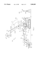
- FIG. 1 is a side view of an earthmoving excavator mounting a tool position determining apparatus according to the present invention, with the excavator arm shown in two configurations;
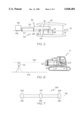
- FIG. 2 is a top schematic view of the earthmoving excavator of FIG. 1, with its tool position determining apparatus mounted thereto;
- FIG. 3 is a side diagrammatic view, with parts broken away, revealing the internal workings of a laser light transmitting and detecting mechanism used in one embodiment of a tool position determining apparatus of the present invention
- FIG. 4 is an enlarged partial top view of a rotating member illustrated in FIG. 3;
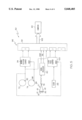
- FIG. 5 is a schematic block diagram of a hardware interface, controlled by software, which supports one embodiment of the tool position determining apparatus of the present invention
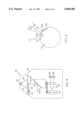
- FIG. 6 is a side view of one embodiment of a reference measuring system according to the principles of the present invention using a level reference laser system
- FIG. 7 is a plan view of a reference ruler used in calibrating a tool position determining apparatus according to the present invention.
- the present invention is broadly directed to an apparatus and method for accurately determining the position of a tool mounted at the end of a pivotable arm forming part of a machine.
- the present invention is herein described in terms of its use on one form of an earthmoving machine, an excavator 10. It is understood that the principles of the present invention are also applicable for use with other types of earthmoving machines including shovels and front-end loaders, construction equipment including high-lift concrete pumps, and other machines employing an arm pivotally mounted to a base at one end and mounting a tool at its other end.
- the present invention can be utilized regardless of whether the machine is mobile or fixed in place.
- the excavator 10 is of the full-track variety and includes a base or platform 12, a cab 14 fixedly mounted on the platform 12 and a segmented arm 16 pivotally attached to and extending out beyond the platform 12.
- arm 16 is shown in a forward extended configuration and (in phantom) in a raised extended configuration.
- Arm 16 has an elbow shaped first arm segment or boom 18 and a second arm segment or dipper stick 20.
- the rear end of the boom 18 is pivotally attached to platform 12 at a first pivot point or axis 22 (shown hidden behind the cab 14) and its leading end is pivotally attached to the rear end of stick 20 at a second pivot point or axis 24.
- a tool or bucket 26 is pivotally attached to the leading end of stick 20 at a third pivot point or axis 28.
- the bucket 26 has a set of teeth 30 positioned along its leading edge for digging into the earth.
- At least one actuating mechanism or first hydraulic cylinder unit 32 is used to pivot the boom 18 about point 22.
- Unit 32 has a cylinder 34 with a rear end pivotally attached to the platform 12 and a rod 36 with a leading end pivotally attached to the boom 18.
- a second cylinder unit 38 for pivoting stick 20 about point 24 has a cylinder 40 with a rear end pivotally attached to the boom 18 and a rod 42 with a leading end pivotally attached to the stick 20.
- a third cylinder unit 44 is used to pivot the bucket 26 about the point 28.
- Cylinder unit 44 has a cylinder 46 with a rear end pivotally attached to the stick 20 at a fourth pivot point or axis 47 and a rod 48 with a leading end pivotally attached to a conventional bucket mechanism 37 at a fifth pivot point or axis 49.
- the bucket mechanism 37 includes a pair of first legs 39 disposed between a pair of second legs 41. One end of each leg 39 and 41 is mounted for rotation to the end of rod 48 along the pivot axis 49. The other end of each leg 39 is mounted for rotation to the back of the bucket 26 at a sixth pivot point or axis 43, and the other end of each leg 41 is mounted for rotation near the leading end, one on either side, of the stick 20 at a seventh pivot point or axis 45.
- an apparatus 50 for determining the position of the bucket 26, in particular the tip of its teeth 30, includes a laser light transceiver 52, at least one first laser light retroreflector 54, a second laser light retroreflector 56, and a third laser light retroreflector 57, all mounted on the machine 10.
- a transceiver 52 examples include U.S. Pat. Nos. 5,076,690 and 5,301,005, which are both incorporated herein by reference in their entirety.
- Each of the reflective targets 54-57 can, for example, be made disposable by being comprised of a thin walled tube (e.g., made of aluminum, PVC fiberglass composite, etc.) having a coating of reflective material on one end and threads on the other end.
- the threaded end of each such target is screwed into a socket (e.g., made of stainless steel) permanently welded or otherwise mounted to the desired location on the machine 10. If it is ever damaged, this type of target can be unscrewed and replaced.
- a socket e.g., made of stainless steel
- Each of the reflectors or targets 54-57 is operatively adapted for reflecting laser light back toward a light source.
- the transceiver 52 is operatively adapted for transmitting a rotating beam of laser light 60 to illuminate and thereby generate reflected laser light 61 from each of the reflectors 54-57 during each rotation of the laser beam 60.
- Laser beam 60 should be of an appropriate size so that the resulting reflected laser light 61 from each of the reflectors 54-57 is able to create discernible START signals and END signals. Since they lie along substantially the same line of travel, the rotating beam of laser light 60 from transceiver 52 and the resulting beam of reflected laser light 61 from each of the reflectors 54-57 are jointly depicted by the same reference line.
- the transceiver 52 is also adapted for detecting the reflected laser light 61 and the angular orientation of the reflected laser light 61 from each reflector 54-57.
- the transceiver 52 is further adapted for generating at least one output signal every time it detects the reflected laser light 61 and its corresponding angular orientation from each reflector 54-57.
- These output signals from the transceiver 52 are continuously transmitted to a computer 62 which is operatively adapted to determine the position of the bucket 26, in particular the tip of its teeth 30, from the output signals as well as stored data on the geometry of the machine 10 and the locations of the transceiver 52 and reflectors 54-57 on the machine 10.
- the computer 62 includes a microprocessor, such as a Motorola 68233, having a suitable memory for storing the software and data necessary to determine the position of the tip of the bucket teeth 30 from the output signals generated with each rotation of the laser beam 60.
- a microprocessor such as a Motorola 68233
- a listing of an exemplary software program for performing such a tool position computation, including the angle measurements, in accordance with the present invention is included following the detailed description.
- the tool position determining function of apparatus 50 can be performed by one or more computer elements positioned wholly or partly on or remote from the machine 10.
- part or all of the computing function could be incorporated into the transceiver unit 52.
- all of the output signals (generated in response to the reflected light 61 from each reflector 54-57 and the corresponding angular orientations) that are detected during each revolution of the beam of light 60, could be combined into one signal, with this one signal being sent to another computer element located remote from the transceiver for subsequent computation to determine the position of bucket 26.
- Each reflector 54-57 is preferably a passive structure, though active sensors may be used as well.
- One type of passive reflector envisioned is a simple tubular or solid bar of suitable material having a circular cross-section and an outer surface that is reflective to laser light (e.g., a steel tube of about 2 inches in diameter, with a polished chrome outer surface).
- the use of such passive reflectors 54-57 reduces the cost and improves the overall ruggedness and service life of the apparatus 50.
- a reflector of such simple construction will be more difficult to damage to the point of affecting the operation of apparatus 50.
- Such ruggedness is particularly necessary for the reflector 57 mounted near the bucket 26, because it is the most exposed and vulnerable to being damaged.
- Such passive reflectors 54-57 can also be easily welded or otherwise attached to the machine 10 to facilitate installation of the apparatus 50.
- a desirable placement of apparatus 50 for the machine 10 shown in FIGS. 1 and 2, includes mounting the transceiver 52 about half way along boom 18 just after its bend.
- One first reflector 54 is mounted near the rear end of the boom motion cylinder 34, about half-way up the front of the cab 14.
- the other first reflector 55 is mounted on the top of the cab 14, in about the middle of its roof and rearward of reflector 54.
- the second reflector 56 is mounted on the stick 20, near the rear end of the bucket motion cylinder 46.
- the third reflector 57 is mounted near the leading end of the bucket motion rod 48 so as to move when the bucket 26 is moved. Satisfactory results have been obtained when the third reflector 57 is mounted between the pivot points 45 and 49, on the second leg 41 located on the same side as the transceiver 52. This location has been found particularly desirable for the apparatus setup procedure described further on below.
- the desirability of the above placement of the transceiver 52 and reflectors 54-57 on a conventional excavator 10 has been proven by using computer simulation, and the results of the computer simulation were verified with actual prototype (i.e., hardware) testing.
- the reflectors 56 and 57 could be mounted to one end of the pivot pins at pivot points 47 and 49, respectfully. However, the pivot pins used in most earthmoving machines, including excavator 10, often fail while in use and must be replaced. Therefore, it is advisable not to mount any of the reflectors 54-57 directly onto a pivot pin.
- the first reflector 54 becomes invisible to the transceiver 52 (i.e., is no longer in line to reflect the beam of light 60) when the boom 18 is pivoted upward beyond a certain point. At that point, only the first reflector 55 on the top of the cab 14 can be seen by the transceiver 52 (i.e., is able to reflect light beam 60). When this occurs, the transceiver 52 begins to generate output signals from the reflected light 61 from reflector 55. These output signals, resulting from reflector 55, are transmitted to the computer 62 and used to determine the position of the bucket 26, in particular the tip of its teeth 30, as described above.
- the output signals from transceiver 52 it is desirable for the output signals from transceiver 52 to be generated only when reflected light 61 is being detected.
- the transceiver 52 used in this embodiment of apparatus 50, is the kind that transmits a rotating beam of laser light 60 that forms a plane 59 of laser light so as to illuminate each of the reflectors 54-57 sequentially (see FIGS. 2 and 3).
- the transceiver 52 transmits a generally vertical plane 59 of laser light substantially parallel to the generally vertical plane in which arm 16 operates (i.e., the plane of the sheet on which FIG. 1 is illustrated).
- the position of the bucket 26 can be determined regardless of whether the operating plane of the arm 16 is oriented vertically, at an angle, or even horizontally.
- each reflector 54-57 may need to be operatively adapted for encoding, or otherwise identifying, the light it reflects in order to uniquely identify to the computer 62 which reflector 54-57 each output signal is associated with.
- the need for bar-coded, or otherwise self-identifying, reflectors can be avoided if the reflectors 54-57 remain in position to be illuminated in the same sequence for each rotation of the beam of light 60, throughout the operating range of motion of the arm 16 (i.e., if the angle ranges in which the transceiver 52 can see the reflectors 54-57 do not overlap).
- the position of the tip of the bucket teeth 30 relative to the platform 12 of machine 10 can be determined once the orientation of the arm 16 (i.e., of the bucket 26 and arm segments 18 and 20) is known.
- the orientation of the arm 16 can be determined using conventional mathematical methods, once the dimensions of the machine 10 (in particular the arm 16), the location of the transceiver 52 and each reflector 54-57 relative to the pivot points 22, 24 and 28, and the geometric relationship between the reflectors 54-57 is determined.
- the dimensions of the machine 10 and the locations of the transceiver 52 and reflectors 54-57 can be measured and stored in the memory of computer 62.
- a setup procedure has been developed which can be used to avoid measuring the relative distances and locations of the various components of the apparatus 10 (i.e., transceiver 52 and reflectors 54-57) on a machine 10.
- the transceiver 52 may be adapted to detect the angular orientation of each reflected beam of light 61 and thus of each reflector 54-57 relative to a known index position, shown as line 63 in FIG. 1, along the path of rotation of the beam of light 60. That is, the angular orientations detected are the angles A 1 , A 2 , A 3 and A 4 between the index position 63 and the reflected light 61 from each reflector 54-57, respectively.
- the first reflector 54 would be in position to always reflect light beam 60. In this way, the other first reflector 55 could be eliminated.
- positioning the first reflector 54 on the cab at this location results in relatively small differences between the various angles A 1 being detected as the arm 16 is articulated. Such small angular differences reduce the accuracy of the computer calculations using the angles A 1 .
- the differences between the various angles A 1 being detected become larger, thereby improving the accuracy of the computer calculations (i.e., optimizing the strength of the figures).
- first reflectors 54 and 55 for the excavator 10 in the locations shown in FIGS. 1 and 2, can help to ensure that the various angles of the boom 18, relative to the excavator platform 12, are being accurately and unambiguously determined.
- the second and third reflectors 56 and 57 are similarly located to maximize the difference between the various angles A 3 and A 4 , respectively.
- the reflectors 54-57 will be illuminated in the same sequence during each rotation of laser beam 60.
- the transceiver 52 is located within each circle described, at least in part, by the movement of reflectors 56 and 57 as they rotate about pivot points 22 and 24, respectively.
- the angle of each arm segment 18 and 20, relative to the platform 12 can be uniquely defined by a single angle measurement computed from the output signals of the transceiver 52.
- the transceiver 52 can be mounted on the cab 14 or elsewhere on the platform 12. In this way, the circles described by the movement of the reflectors 56 and 57 on such machines are large enough to encompass the transceiver 52, even though the transceiver 52 is not mounted on the arm 16.
- the apparatus 50 can be used with an automatic or manually operated machine 10. It is envisioned that the transceiver 52 will be powered off of a portion of the existing electrical system of the machine 10. For example, the transceiver 52 can be electrically connected to the machine's lights. The lights on a typical excavator 10 are often mounted on the front of the cab 14 near the arm 16.
- the apparatus 50 To aid an operator in controlling the position of the bucket 26, it is desirable for the apparatus 50 to include some kind of a display for graphically, pictorially or otherwise visually indicating the position of the tip of the bucket teeth 30 relative to a grade elevation, in response to the position computations performed by the computer 62.
- a basic graphical user interface (GUI) software program can be used in displaying the orientation of the arm 16, according to conventional software techniques. Such GUI programs are well known and, therefore, not described in detail herein.
- the GUI software can be run externally on a separate laptop or on any other suitable computer. It is desirable for the GUI program to be the type that runs under MS Windows and which displays a schematic drawing of the arm 16 on a display window.
- the Y-axis and X-axis position i.e., the elevation and extension
- the Y-axis and X-axis position i.e., the elevation and extension
- a horizontal line indicating the ground surface level
- a second thicker line representing the desired digging depth
- any suitable laser transmitting and detecting mechanism can be used for the laser transceiver 52, such as that manufactured by Spectra-Physics Laserplane, Inc., the assignee of the present application, Model No. 2190, under the trademark CAPSYTM (Computer Aided Positioning System).
- a housing 64 is used to contain one example of such a transceiver 52.
- This transceiver 52 includes an electric motor 66 mounted to rotate a shaft 68.
- a member 70, such as a code wheel, and a light diverting mirror 72 are mounted on the shaft 68.
- a member pick up element 92 detects the rotation of the member 70 and the passage of an index element 73 mounted on member 70.
- index element 73 may be of any configuration which produces a reference pulse that is distinguishable from signals produced by pickup elements 84 (see discussion below).
- an index pickup element 96 can be used with an index wheel 74, separately mounted to shaft 68, for providing the single reference pulse.
- a solid state laser 76 directs the beam of light 60 onto the rotating mirror 72 so that a plane of rotating light is created.
- the orientation of this plane of light i.e., vertical, tilted or horizontal
- An advantage of this type of transceiver 52 is that a precisely oriented plane is not essential for the angle calculations.
- the present invention can be used on arms which move up and down in a vertical plane, side to side in a horizontal plane or at any angle therebetween.
- the rotating laser beam 60 strikes the reflectors 54-57 during each revolution of the shaft 68, the resulting reflected light 61 travels back to the transceiver 52 and is directed by the mirror 72, along substantially the same path as that originally followed by beam 60, to a suitable detector, such as a photo detector 78.
- the photo detector 78 transforms the reflected light 61 into an analog signal.
- This analog signal is then transmitted to a signal processor 80 (see FIG. 5), which outputs two digital signals, for reasons discussed below. It may be desirable for the rotating mirror 72 to divert the reflected light beam 61 through a collimating lens 82, or other suitable structure, for focusing the reflected light 61 toward the photo detector 78.
- the time it takes for one complete rotation of beam 60 is directly related to a total angle of 360 degrees.
- the angles A 1 , A 2 , A 3 and A 4 between the reflectors 54-57 and the index position 63 can thus, theoretically, be determined by adding about half of the time that each reflector 54-57 remains illuminated by beam 60 (i.e., the time that reflected light 61 from each reflector 54-57 is being detected) with the time between the detection of the index position 63 (whether indicated by the reference pulse provided by the index element 73 or wheel 74) and the moment in time that the reflection of beam 60 by each reflector 54-57 begins, respectively.
- the orientation of the arm 16, and thus the location of the bucket 26 and its teeth 30, can then be calculated from these angles A 1 , A 2 , A 3 and A 4 once the geometric relationship between the transceiver 52, the reflectors 54-57 and the machine 10 is known.
- the member or code wheel 70 has a plurality of angularly positioned elements, such as in the form of apertures 84 spaced around its periphery.
- the index element 73 provides an indication of the index position 63.
- the apertures 84 divide a revolution of the wheel 70 into a plurality of generally equal partial revolutions.
- the code wheel 70 may divide a revolution into one thousand generally equal parts positioned approximately 0.36 degrees apart by spacing one thousand elements or apertures 84 around the periphery of the member 70. The size and spacing of these apertures 84 are greatly exaggerated in the drawing for clarity of illustration.
- ⁇ 84a is the measured angle between the index position 63 and the aperture 84a
- ⁇ 84b is the measured angle between the index position 63 and the aperture 84b
- Tm is the time elapsed between passage of the previous aperture, here aperture 84a, and the moment M in time that the reflected light 61 strikes the sensor or photodetector 78
- Tcw is the time it takes the code wheel 70 to move between element 84a and element 84b.
- the use of the code wheel 70 and the motor 66 by the transceiver 52 is supported by a hardware interface 86.
- An event occurs every time an aperture 84 on the code wheel 70 passes or one of the reflectors 54-57 commences or ends a reflection of the beam of light 60. Due to the high precision time measurements required between each adjacent pair of apertures 84, a reference clock 88 is used in keeping a record of an event. If an event occurred during this time, it is stored in a circuit 90, such as a 32 bit first-in-first-out circuit. The circuit 90 records the movement of the code wheel 70 at register zero.
- the actual element or aperture 84 which is currently passing is sensed at the member or code wheel pickup element 92 and counted by a member rotation counter 94.
- the member pick up element 92 in response to the index element 73, sends an index position signal to reset the member rotation counter 94. If the index wheel 74 is used, the index pickup element 96 sends the index position signal to reset the counter 94.
- the member pickup element 92 is operatively adapted for detecting movement of each of the elements 84 past a predetermined point as the member 70 rotates. It is desirable for the pickup element 92, and if applicable pickup element 96, to comprise a light source paired with a photodetector element.
- the signal processor 80 is operatively adapted to detect when receiving optics 98, here consisting of collimating lens 82 and photodetector 78, is either commencing or ending receipt of the reflected light 61 from the reflectors 54-57.
- the signal processor 80 can transform the analog signal from photodetector 78 into two digital signals which are received at register 1 of circuit 90.
- the first digital signal represents a START signal which indicates that the reflection of beam 60 from one of the reflectors 54-57 to the transceiver 52 is commencing, and the second digital signal is an END signal which indicates that the reflection is ending.
- the signal processor 80 is operatively adapted to digitize the analog signal from the photodetector 78.
- the digital signal is then analyzed to determine when a reflection of the beam 60 from one of the reflectors 54-57 is starting and when the reflection is ending. Such analysis may include indicating successive START and END signals as the digital signal exceeds and falls below a certain value.
- register 2 receives signals for measuring the time elapsing between the passage of the last aperture 84 and an event, which event may be the time Tm or the time Tcw shown in FIG. 4.
- a clock pulse counter 100 is reset at every passage of an aperture 84 as detected by the element 92 and, consequently, the counter 100 counts the time elapsing between the passage of each pair of adjacent elements 84.
- Information regarding the capacity of circuit 90 is stored in register 3.
- the circuit 90 stores the information received and provides an output signal 102 to the computer 62, which includes a microprocessor having a memory.
- the computer 62 is responsive to the output signal 102 and computes the coordinates of the reflectors 54-57 relative to the machine 10. After determining the position of at least reflectors 54, 56 and 57, the computer 62 can compute the orientation of the bucket 26 and the position of the teeth 30 relative to the platform 12 of machine 10 because the geometric relationship between the reflectors and the machine is in the computer memory.
- each reflector may have a unique series of START and END signals resulting from the transceiver 52 detecting reflective light from each bar in the code as the laser beam 60 sweeps past the reflector.
- an elevation measuring system it is desirable for an elevation measuring system to be used with the bucket position determining apparatus 50 in order to determine the location of the bucket 26 relative to a spacial reference point, such as a reference grade elevation 104.
- a spacial reference point such as a reference grade elevation 104.
- the software of the computer 62 can be adapted to compute the position of the bucket 26 relative to the grade elevation 104.
- the position of the bucket 26 relative to this grade elevation 104 can be determined by simply measuring this distance and storing it in the computer 62.
- the computer 62 can be programmed to then utilize this measured distance in computing the position of the bucket 26 relative to the grade elevation 104.
- GPS global positioning system
- the GPS 103 is operatively adapted for making at least determinations about the elevation of machine 10 by providing the computer with a signal indicative of the position of a point on the machine 10 relative to the grade elevation. It may be desirable to use a GPS 103 capable of making three-dimensional position location determinations, with centimeter accuracy.
- GPS global positioning system
- the location of the machine 10 can be determined anywhere on the surface of the job site.
- the location of the bucket 26 on the surface of the job site can be determined by using the apparatus 50 as described above.
- a typical global positioning system 103 includes a plurality of time-synchronized satellites broadcasting signals indicating their orbital position above the earth.
- a reference receiver 106 is positioned remotely from the machine 10 at a known elevation relative to the reference grade elevation 104.
- the receiver 106 has a first antenna 108 for receiving signals from the satellites.
- a secondary receiver 110 is mounted at a known location on the machine 10 and has a second antenna 112 for also receiving signals from the satellites.
- the second antenna 112 is in communication with and is free to move with respect to the first antenna 108.
- At least one GPS computer is associated with at least one of the receivers 106 and 110, is programmed to collect and analyze signals received by each antenna 108 and 112, and calculates at least the difference in elevation between the two antennas 108 and 112.
- the computer 62 can be programmed to utilize this calculated elevation difference in computing the position of the bucket 26 relative to the grade elevation 104. It may also be desirable for the GPS computer to calculate the location of the two antennas 108 and 112 in three dimensions, relative to one another.
- the GPS computer can be separate from or form a part of the computer 62 and can be remote from or mounted on the machine 10.
- the elevation measuring system can also be a level reference laser system 114, such as that disclosed in U.S. Pat. No. 5,375,663, which is incorporated herein by reference in its entirety.
- a typical level reference laser system 114 includes a laser transmitter 116 mounted remotely from the machine 10 for transmitting a beam of laser light and a laser receiver 118 mounted at a known location on the platform 12 of the machine 10 for detecting the laser beam.
- the transmitter 116 rotates the beam of laser light to form a reference plane of laser light 120 a known distance above the reference grade 104. It is desirable for the transmitter 116 to be operatively adapted so that the laser reference plane 120 remains substantially parallel to the reference grade 104.
- the receiver 118 has a plurality of sensors disposed along its length in a known relationship to the platform 12, with at least one sensor crossing and being illuminated by the laser reference plane 120 at all times during the operation of the machine 10. Each sensor detects when it is illuminated and sends a corresponding signal to a computer, such as computer 62, indicating the distance between the reference plane 120 and the platform 12.
- the computer 62 can be programmed to utilize this signal in computing the position of the bucket 26 relative to the grade elevation 104, by knowing the relationship between the reference plane 120 and the reference grade 104.
- the level reference laser system 114 may include a dual axis x-y sensor 122 mounted on the platform 12 of machine 10.
- the sensor 122 provides the computer 62 with signals corresponding to the pitch of the platform 12 (indicated by the arrows 123).
- the computer 62 can be programmed to utilize the detected distance between the reference plane 120 and the platform 12, indicated by signals from the sensors of receiver 118, with the signals from the sensor 122 to determine the angle or slant of the platform 12 relative to the reference plane 120 of laser light, and thereby relative to the reference grade 104.
- Excavator specific parameters include specific dimensions of the excavator 10, in particular the dimensions of the arm 16.
- the specific parameters that are relevant to the type of excavator 10 shown in FIG. 1 include the effective lengths of the boom 18 and of the stick 20, and the dimensions of the bucket mechanism elements 39 and 41.
- the installation specific parameters describe how the apparatus 50 is mounted on the excavator 10 and typically vary for each installation of the apparatus 50, even for the same type of excavator 10.
- the installation specific parameters include the relative distances and locations of the various components of the apparatus 50 such as, for example, the location of the transceiver 52 on the boom 18, the location of the first reflectors 54 and 55 on the excavator cab 14, the location of the second reflector 56 on the stick 20 and the location of the third reflector 57 on the bucket mechanism 37.
- the above described specific parameters may be different for different types of apparatus 50 and machines 10.
- the above installation specific parameters can either be measured or otherwise obtained during the installation of the apparatus 50.
- the excavator specific parameters can either be measured directly or obtained from the equipment specifications from the manufacturer of the excavator 10. Making actual measurements of the excavator 10 can be difficult and time consuming, and sometimes almost impossible. Such dimensions can be easily and quickly obtained from the excavator's technical specifications, but these may prove inaccurate due to significant differences between the actual dimensions of the excavator 10 and its designed dimensions. In addition, the dimensions of the excavator 10 will likely change with time as a result of the normal wear and tear typically experienced by earthmoving equipment.
- a setup procedure for use during the installation of the apparatus 50 on a typical hydraulic earthmoving excavator 10 has been developed to determine many of the dimensional relationships (i.e., parameters), without having to make actual measurements.
- this setup procedure can be used to at least determine the installation specific parameters.
- this setup procedure can also be used to subsequently verify or confirm these parameters, as part of a periodic maintenance procedure.
- one embodiment of the above setup procedure includes using a set of three light reflectors with known relative locations to calculate the unknown locations of the reflective targets 54-57.
- a reference ruler 124 can be used which includes three reflectors 126, 127 and 128.
- this setup procedure uses numerical calculation techniques similar to those that can be used in operating the transceiver 52, as is explained in the previously incorporated U.S. Pat. No. 5,076,690.
- Each reflector 126-128 is retroreflective so as to reflect laser light back toward a light source.
- the reflectors 126-128 can be self-identifying, such as with unique bar code patterns on their reflective surfaces 130.
- the reflectors 126-128 can also be the anonymous type of a simple reflective construction.
- the distance between each of the reflectors 126-128 is fixed and known. Satisfactory results have been obtained by using a 3400 mm long reference ruler having the middle reflector 127 mounted 1600 mm from one end of the ruler 124 and 1800 mm from the other end of the ruler 124. Satisfactory results should also be obtained when the center reflector 127 is mounted exactly in the middle of the ruler 124.
- One exemplary setup procedure includes a boom motion step, a stick motion step and a bucket motion step.
- the excavator 10 In the boom motion step, it is desirable for the excavator 10 to be parked on a flat surface. This flat surface need not be horizontal.
- the ruler 124 is then positioned on the ground in front of the excavator 10, beneath the arm 16, so that the reflectors 126-128 of the ruler 124 are aligned with the plane 59 of laser light 60 emitted by the laser transceiver 52. That is, the reflectors 126-128 are in position to reflect the laser beam 60 back to the transceiver 52.
- a LaserEye® receiver (not shown), such as that manufactured by Spectra-Physics Laserplane, Inc., the assignee of the present application, Model No. 1175, can be used to locate the laser plane 59 for alignment with the reflectors 126-128.
- the excavator boom 18 is rotated about its pivot point 22 from its lowest possible configuration (i.e., the fully extended view of arm 16 on the bottom of FIG. 1), through a number of intermediate positions and to the highest configuration where all of the reflectors 54-57 remain visible to the transceiver 52.
- the angle measuring capability of the transceiver 52 is used to make a set of two or more angle measurements of the reflectors 126-128 relative to the index position 63.
- Each set of angles is stored and used to average out small disturbances and instabilities of the reflector position sensing system of the transceiver 52 that may affect the angle measurements of the ruler reflectors 126-128 at each boom position. For each incremental rotation of the boom 18, it may be necessary to wait 10-20 seconds or so in order to allow vibrations of the excavator arm 16 to dampen out before angular measurements of the ruler reflectors 126-128 are taken. It may also be necessary to wait for vibrations to dampen out after moving the stick 20, as described below. The stick 20 and the bucket 26 are kept relatively stationary throughout the rotations of boom 18.
- a number of the installation specific parameters can be calculated using the data provided by the above described boom motion step and the exemplary software program, for performing the setup procedure, included herein. These calculated parameters include: (1) the location of the boom pivot point 22 relative to the reference ruler 124 (i.e., the surface of the ground 104 on which the ruler 124 lies) and, therefore, the elevation of the pivot point 22 relative to the ground surface level 104; (2) the radius of the arc or curve defined by the various positions of the transceiver 52 as the boom 18 is rotated (i.e., the distance between the boom pivot point 22 and the transceiver 52); (3) the location of either first reflector 54 and 55 relative to the boom pivot point 22 and the reference ruler 124 on the ground 104; and (4) the value of the constant reference angle between the transceiver index position 63 and the boom pivot point 22.
- the distance between the reflectors 126-128 on the ruler 124 and by measuring the angle between each reflector 126-128, with the angle measuring capabilities of transceiver 52 can be determined using the position determining capabilities of the transceiver 52 (i.e., the position computing capabilities of the computer 62).
- the distance between the transceiver 52 and the boom pivot point 22 can be easily and accurately determined, without having to actually measure the distance, by plotting this curve and using simple geometric principles to locate the point of rotation 22.
- the reference ruler 124 is mounted to the stick 20, for example, on the second and third reflectors 56 and 57, rather than being positioned on the ground.
- the ruler 124 is oriented lengthwise along the length of the stick 20, with its reflectors 126-128 in line with the laser plane 59.
- the exact location of the ruler 124 on the stick 20 is not necessarily critical because the angle measurements of its reflectors 126-128 and of the targets 45, 56 and 57 can provide the information needed to determine the relationship between the ruler 124 and the reflective targets 56 and 57.
- the angle measurements from the temporary reference reflector at point 45 may not be necessary to determining this relationship.
- the trajectory or path followed by the ruler 124 can be calculated. Knowing the trajectory followed by the ruler 124 and the angular relationship between all of the reflectors 126-128, 45, 56 and 57 enables the relationship between the ruler 124 and the targets 56 and 57 to be determined.
- the ruler 124 is mounted behind the reflective targets 56 and 57 such that the targets 56 and 57 and the ruler reflectors 126-128 are able to reflect the laser light 60 from the transceiver 52.
- a temporary reference reflector (not shown), similar to the reflective targets 56 and 57, can be mounted at pivot point 45, for example, by being threaded into an existing threaded hole at point 45.
- the boom 18 is fixed at an arbitrary configuration which allows the stick 20 to rotate through its full range without the bucket 26 hitting the ground 104.
- the bucket 26 is kept relatively stationary throughout the rotation of the stick 20. With the boom 18 and the bucket 26 kept stationary, the stick 20 is rotated about its pivot point 24, through its full range of motion. As with the boom motion step, the stick 20 is rotated incrementally to approximately 20 positions within its full range of motion, with a set of two or more angle measurements being made at each position of the stick 20.
- a number of installation specific parameters can be calculated using the data provided by the above described stick motion step and the exemplary software program, for performing the setup procedure, included herein. These calculated parameters include: (1) the distance between the transceiver 52 and the stick pivot point 24; (2) the distance between the pivot point 24 and the second reflector 56; (3) the angle 56-24-45 defined by two lines diverging from the pivot point 24, one extending to the reflector 56 and the other to the pivot point 45; (4) the location of the reflector 56 relative to the pivot points 24 and 45, which is determined by using the distance and angle of parameters (2) and (3), above; (5) the value of the constant reference angle between the transceiver index position 63 and the stick pivot point 24; and (6) the distance between the pivot point 45 and the third reflector 57, using the temporary reference reflector mounted at the pivot point 45.
- the location of the transceiver 52 on the boom 18 can be calculated using the distance between the pivot points 22 and 24, the distance between the transceiver 52 and the point 22, and the distance between the transceiver 52 and the point 24.
- the distance between the points 22 and 24 can be obtained by making measurements or from the excavator's technical specification.
- the distances between the transceiver 52 and the two pivot points 22 and 24 can be obtained as described above.
- the spacial orientation of the ruler 124 (i.e., of the stick 20) can be determined, in addition to the distance between the ruler 124 and the transceiver 52.
- the angle between the index position 63 and any unknown reflector on the stick 20 i.e., targets 56 and 57, and the reference reflector temporarily mounted at the pivot point 45
- the new position of the ruler 124 is calculated, by again averaging multiple angle measurements for each of its three reflectors 126-128 and for each of the reflectors 45, 56 and 57 on the stick 20.
- the data on the orientation of the ruler 124 and the angle corresponding to one of the stick reflectors 45, 56 or 57 is enough to set up an equation with one unknown, i.e., the distance between the transceiver 52 and the stick reflector 45, 56 or 57 in question.
- a number of angle measurements are taken at each position of the stick 20 to provide enough data to ensure an accurate solution of the equation and, thereby, obtain the distance from the transceiver 52 and the applicable stick reflector 45, 56 or 57.
- the distance from the center of the third reflector 57 and the bucket mechanism pivot point 49 is measured.
- This third step in the exemplary setup procedure enables the parameters to be determined which describe the bucket mechanism 37.
- the only installation dependent parameter that has to be determined is the angle 49-45-57 defined by two diverging lines from the pivot point 45, one extending to the pivot point 49 and the other to the target 57.
- the most convenient method of determining the dimensions of the bucket mechanism 37 is to use the technical specifications of the excavator 10. However, it may be more accurate to measure the necessary dimensions. Accordingly, the angle 49-45-57 is determined by measuring the length (i.e., distance) of each side of the triangle defined by the pivot points 45 and 49 and the target 57.
- the above-described setup procedure is effective, uncomplicated and has been performed in as little as half of an hour.
- This exemplary setup procedure can be performed by one person and the use of special equipment and tools can be kept to a minimum. Three accessories are used during the procedure; a reference ruler with three targets attached to it, a reference reflector that can be mounted at the pivot point 45, and some form of distance measuring device, such as vernier calipers or a tape measure.
- the general principles described above in this exemplary setup procedure may be applicable to setting up various types of machines suitable for being used with the present apparatus. Accordingly, these principles are not intended to be limited to being used with excavators or other types of earthmoving equipment.
- the present invention for determining the position of a bucket, or other tool, mounted on the end of an arm exhibits a number of advantages.
- the present invention can use position measuring components (e.g., the light reflective targets 54-57) of relatively simple and rugged, or at least easily replaceable, construction. These components can be mounted at those locations on the arm which are exposed to the greatest risk of being damaged, very often arm's leading end. In this way, the present invention is better able to withstand the adverse working conditions often encountered in many applications, such as excavating earth at a construction site.
- the present invention is also capable of determining the position of the tool with a high degree of accuracy, at least in part, because it can employ laser technology in its position measuring. Accuracies of up to approximately ⁇ 1 cm in grade or elevation (i.e., in the Y-axis) and ⁇ 2 cm in extension (i.e., in the X-axis) have been obtained. With time, the degree of accuracy obtained may be affected by a number of effects, such as wear of the bucket teeth 30, slack in the joints of the arm 16, normal wear and tear of the transceiver 52 or the reflectors 54-57 (e.g., a reflector being bent).
- the above described installation setup procedure can be used to recalibrate the apparatus 50 whenever the accuracy of the present invention comes into question or as part of a routine maintenance procedure.
- the present invention is simple to install, even on construction equipment, such as conventional earthmoving machines, and simple to setup, even at an outdoor job-site.
- the present invention can be used with a variety of machines which have a tool mounted on a pivotable arm, including different types of construction equipment and robotic arms.
- the present invention can be used with such a pivotable arm regardless of the orientation of the plane in which the arm moves.
- the following is an exemplary software program, to be stored in the computer 62, (1) for controlling the hardware interface 86 and (2) for using a calibration table of the transceiver's reflector position sensing system: ##SPC1##
- the following is an exemplary software program, to be stored in the computer 62, (3) for performing reference angle measurements using the transceiver 52, for all of the reflectors 54-57, and using the calibration table of the transceiver's reflector position sensing system: ##SPC2##
- the following is an exemplary software program, to be stored in the computer 62, (4) for performing a setup procedure for installing and subsequently recalibrating the apparatus 50 on a typical earthmoving excavator 10 and (5) computing the coordinates of the reflectors 54-57 relative to the transceiver 52 and the position of the tip of the teeth 30 of bucket 26 relative to the machine 10 and a spacial reference point (i.e., the ground 104): ##SPC3##
Abstract
Description
Angle=∠84a+(Tm/Tcw)*(∠84b-∠84a)
Claims (28)
Priority Applications (1)
| Application Number | Priority Date | Filing Date | Title |
|---|---|---|---|
| US08/774,203 US5848485A (en) | 1996-12-27 | 1996-12-27 | System for determining the position of a tool mounted on pivotable arm using a light source and reflectors |
Applications Claiming Priority (1)
| Application Number | Priority Date | Filing Date | Title |
|---|---|---|---|
| US08/774,203 US5848485A (en) | 1996-12-27 | 1996-12-27 | System for determining the position of a tool mounted on pivotable arm using a light source and reflectors |
Publications (1)
| Publication Number | Publication Date |
|---|---|
| US5848485A true US5848485A (en) | 1998-12-15 |
Family
ID=25100529
Family Applications (1)
| Application Number | Title | Priority Date | Filing Date |
|---|---|---|---|
| US08/774,203 Expired - Lifetime US5848485A (en) | 1996-12-27 | 1996-12-27 | System for determining the position of a tool mounted on pivotable arm using a light source and reflectors |
Country Status (1)
| Country | Link |
|---|---|
| US (1) | US5848485A (en) |
Cited By (59)
| Publication number | Priority date | Publication date | Assignee | Title |
|---|---|---|---|---|
| US6016616A (en) * | 1993-11-11 | 2000-01-25 | J. Mastenbroek & Company Limited | Sensor positioning apparatus for trench excavator |
| US6122601A (en) * | 1996-03-29 | 2000-09-19 | The Penn State Research Foundation | Compacted material density measurement and compaction tracking system |
| US6209232B1 (en) * | 1996-09-04 | 2001-04-03 | Shin Caterpillar Mitsubishi Ltd. | Construction machine with function of measuring finishing accuracy of floor face smoothed thereby |
| US6263595B1 (en) * | 1999-04-26 | 2001-07-24 | Apache Technologies, Inc. | Laser receiver and angle sensor mounted on an excavator |
| US6336077B1 (en) * | 1999-06-07 | 2002-01-01 | BOUCHER GAéTAN | Automatic monitoring and display system for use with a diggins machine |
| US6336280B1 (en) * | 2000-06-29 | 2002-01-08 | Mississippi State University | Self-propelled rotary excavator |
| US6366345B1 (en) * | 2000-01-28 | 2002-04-02 | Mitsubishi Denki Kabushiki Kaisia | Monitor for montoring periphery of vehicle |
| US6418364B1 (en) * | 2000-12-13 | 2002-07-09 | Caterpillar Inc. | Method for determining a position and heading of a work machine |
| US6435283B1 (en) | 1998-06-17 | 2002-08-20 | Kabushiki Kaisha Topcon | Rotary laser irradiating apparatus and construction machine control system |
| US20030137658A1 (en) * | 2002-01-21 | 2003-07-24 | Fumio Ohtomo | Construction machine control system |
| US6633286B1 (en) * | 2000-09-01 | 2003-10-14 | Rockwell Collins, Inc. | Method and apparatus for providing a monitor deployment |
| US6691437B1 (en) | 2003-03-24 | 2004-02-17 | Trimble Navigation Limited | Laser reference system for excavating machine |
| US6711838B2 (en) * | 2002-07-29 | 2004-03-30 | Caterpillar Inc | Method and apparatus for determining machine location |
| US6728619B2 (en) * | 2000-03-31 | 2004-04-27 | Hitachi Construction Machinery Co., Ltd. | Failure measure outputting method, output system, and output device |
| US6741343B2 (en) * | 1998-02-10 | 2004-05-25 | Toolz, Ltd. | Level with angle and distance measurement apparatus |
| US6862509B2 (en) * | 2000-12-01 | 2005-03-01 | Putzmeister Aktiengesellschaft | Device for operating the articulated mast of a large manipulator |
| US20050187731A1 (en) * | 1997-11-28 | 2005-08-25 | Lars Ericsson | Device and method for determining the position of a working part |
| US20050197756A1 (en) * | 1998-11-27 | 2005-09-08 | Taylor Arthur J. | Method and system for performing non-contact based determination of the position of an implement |
| US20060012777A1 (en) * | 2004-07-13 | 2006-01-19 | Talbot Nicholas C | Combination laser system and global navigation satellite system |
| US7012237B1 (en) | 2003-10-29 | 2006-03-14 | Apache Technologies, Inc. | Modulated laser light detector |
| US20060085118A1 (en) * | 2004-10-20 | 2006-04-20 | Leica Geosystems Ag | Method and apparatus for monitoring a load condition of a dragline |
| US20060123673A1 (en) * | 2004-11-23 | 2006-06-15 | Caterpillar Inc. | Grading control system |
| US20060201007A1 (en) * | 2005-03-14 | 2006-09-14 | Piekutowski Richard P | Method and apparatus for machine element control |
| US20070052950A1 (en) * | 2004-07-13 | 2007-03-08 | Trimble Navigation Limited | Navigation system using both GPS and laser reference |
| US20080015811A1 (en) * | 2006-07-12 | 2008-01-17 | Apache Technologies, Inc. | Handheld laser light detector with height correction, using a GPS receiver to provide two-dimensional position data |
| US7323673B1 (en) | 2005-03-16 | 2008-01-29 | Apache Technologies, Inc. | Modulated laser light detector with discrete fourier transform algorithm |
| EP1983305A1 (en) | 2007-04-20 | 2008-10-22 | Agatec | Independent position sensor and system for determining the position of a work engine tool by means of position sensors |
| US20090058401A1 (en) * | 2007-08-31 | 2009-03-05 | Caterpillar Inc. | Machine with a position-sensing system |
| US20090112472A1 (en) * | 2007-10-26 | 2009-04-30 | Deere & Company | Three Dimensional Feature Location From An Excavator |
| US20090158625A1 (en) * | 2007-12-21 | 2009-06-25 | Caterpillar Trimble Control Technologies Llc | Control system for tool coupling |
| WO2009121122A1 (en) * | 2008-04-01 | 2009-10-08 | Cmte Development Limited | A method for position-calibration of a digging assembly for electric mining shovels |
| US20100096148A1 (en) * | 2008-10-21 | 2010-04-22 | Agatec | Independent position sensor and a system to determine the position of a tool on a works machine using position sensors |
| US20100215434A1 (en) * | 2009-02-20 | 2010-08-26 | Caterpillar Trimble Control Technologies Llc | Wireless sensor with kinetic energy power arrangement |
| US20100222970A1 (en) * | 2007-10-18 | 2010-09-02 | Sumitomo Heavy Industries, Ltd. | Turning drive control apparatus and construction machine including the same |
| US7838808B1 (en) | 2005-03-16 | 2010-11-23 | Trimble Navigation Limited | Laser light detector with reflection rejection algorithm |
| US20100312428A1 (en) * | 2003-03-20 | 2010-12-09 | Roberge Andre C | Gnss guidance and machine control |
| US20110196583A1 (en) * | 2008-11-03 | 2011-08-11 | Putzmeister Engineering Gmbh | Mobile work machine having support booms |
| US8639416B2 (en) | 2003-03-20 | 2014-01-28 | Agjunction Llc | GNSS guidance and machine control |
| US8768558B2 (en) | 2007-01-05 | 2014-07-01 | Agjunction Llc | Optical tracking vehicle control system and method |
| US8817238B2 (en) | 2007-10-26 | 2014-08-26 | Deere & Company | Three dimensional feature location from an excavator |
| DE112007000285B4 (en) * | 2006-02-01 | 2014-10-23 | Trimble Navigation Ltd. | Position indicating guide control system and method for the same |
| US8930091B2 (en) | 2010-10-26 | 2015-01-06 | Cmte Development Limited | Measurement of bulk density of the payload in a dragline bucket |
| US20150161872A1 (en) * | 2010-02-01 | 2015-06-11 | Trimble Navigation Limited | Worksite proximity warning |
| US20150299989A1 (en) * | 2012-11-20 | 2015-10-22 | Komatsu Ltd. | Working machine and method of measuring work amount of working machine |
| US9211832B1 (en) * | 2012-05-16 | 2015-12-15 | S.A.S. Of Luxemburg, Ltd. | Salvage hold down attachment for excavators |
| US9222771B2 (en) | 2011-10-17 | 2015-12-29 | Kla-Tencor Corp. | Acquisition of information for a construction site |
| US9227820B2 (en) | 2010-02-01 | 2016-01-05 | Trimble Navigation Limited | Sensor unit system |
| US9248998B2 (en) | 2010-02-01 | 2016-02-02 | Trimble Navigation Limited | Lifting device with load hazard avoidance using a sensor coupled with the load line |
| US9442476B2 (en) | 2011-06-30 | 2016-09-13 | Rockwell Automation Technologies, Inc. | Multiple deployment of applications with multiple configurations in an industrial automation environment |
| US20160290834A1 (en) * | 2013-11-21 | 2016-10-06 | Ecovacs Robotics Co. Ltd. | Distance measuring device and method thereof for seeking distance measuring starting point |
| US9880562B2 (en) | 2003-03-20 | 2018-01-30 | Agjunction Llc | GNSS and optical guidance and machine control |
| US9995017B1 (en) * | 2016-12-08 | 2018-06-12 | Caterpillar Trimble Control Technologies Llc | Excavator implement length and angle offset determination using a laser distance meter |
| US10106994B2 (en) * | 2013-04-09 | 2018-10-23 | Ttcontrol Gmbh | Control system and method for controlling the orientation of a segment of a manipulator |
| US10358788B2 (en) * | 2016-12-21 | 2019-07-23 | Caterpillar Trimble Control Technologies Llc | Excavator implement angle determination using a laser distance meter |
| US10458099B2 (en) | 2004-08-26 | 2019-10-29 | Caterpillar Trimble Control Technologies Llc | Auto recognition of at least one standoff target to determine position information for a mobile machine |
| US20200080287A1 (en) * | 2017-07-14 | 2020-03-12 | Komatsu Ltd. | Work machine system and control method |
| CN110939135A (en) * | 2019-11-19 | 2020-03-31 | 中交疏浚技术装备国家工程研究中心有限公司 | Positioning and orientation method and system applied to slope paving engineering machinery operation |
| USRE48527E1 (en) | 2007-01-05 | 2021-04-20 | Agjunction Llc | Optical tracking vehicle control system and method |
| US20220316172A1 (en) * | 2021-03-30 | 2022-10-06 | Darrell Cobb | Backhoe Camera Assembly |
Citations (16)
| Publication number | Priority date | Publication date | Assignee | Title |
|---|---|---|---|---|
| US3997071A (en) * | 1975-08-14 | 1976-12-14 | Laserplane Corporation | Method and apparatus for indicating effective digging depth of a backhoe |
| US4129224A (en) * | 1977-09-15 | 1978-12-12 | Laserplane Corporation | Automatic control of backhoe digging depth |
| US4288196A (en) * | 1979-06-14 | 1981-09-08 | Sutton Ii James O | Computer controlled backhoe |
| US4393606A (en) * | 1980-08-30 | 1983-07-19 | Friedrich Wilh. Schwing Gmbh | Excavator with laser position indicator |
| US4888890A (en) * | 1988-11-14 | 1989-12-26 | Spectra-Physics, Inc. | Laser control of excavating machine digging depth |
| US4895440A (en) * | 1988-08-22 | 1990-01-23 | Spectra-Physics, Inc. | Laser-based measurement system |
| US5000564A (en) * | 1990-03-09 | 1991-03-19 | Spectra-Physics, Inc. | Laser beam measurement system |
| US5076690A (en) * | 1990-05-14 | 1991-12-31 | Spectra-Physics Laserplane, Inc. | Computer aided positioning system and method |
| US5100229A (en) * | 1990-08-17 | 1992-03-31 | Spatial Positioning Systems, Inc. | Spatial positioning system |
| US5177489A (en) * | 1989-09-26 | 1993-01-05 | Magnavox Electronic Systems Company | Pseudolite-aided method for precision kinematic positioning |
| US5301005A (en) * | 1993-02-10 | 1994-04-05 | Spectra-Physics Laserplane, Inc. | Method and apparatus for determining the position of a retroreflective element |
| US5375663A (en) * | 1993-04-01 | 1994-12-27 | Spectra-Physics Laserplane, Inc. | Earthmoving apparatus and method for grading land providing continuous resurveying |
| US5438771A (en) * | 1994-05-10 | 1995-08-08 | Caterpillar Inc. | Method and apparatus for determining the location and orientation of a work machine |
| US5579102A (en) * | 1991-06-17 | 1996-11-26 | Spatial Positioning Systems, Inc. | Transmitter and receiver units for spatial position measurement system |
| US5600436A (en) * | 1994-01-05 | 1997-02-04 | Caterpillar Inc. | Apparatus and system for determining terrestrial position |
| US5666792A (en) * | 1994-12-30 | 1997-09-16 | Mullins; Donald B. | Remotely guided brush cutting, chipping and clearing apparatus and method |
-
1996
- 1996-12-27 US US08/774,203 patent/US5848485A/en not_active Expired - Lifetime
Patent Citations (17)
| Publication number | Priority date | Publication date | Assignee | Title |
|---|---|---|---|---|
| US3997071A (en) * | 1975-08-14 | 1976-12-14 | Laserplane Corporation | Method and apparatus for indicating effective digging depth of a backhoe |
| US4129224A (en) * | 1977-09-15 | 1978-12-12 | Laserplane Corporation | Automatic control of backhoe digging depth |
| US4288196A (en) * | 1979-06-14 | 1981-09-08 | Sutton Ii James O | Computer controlled backhoe |
| US4393606A (en) * | 1980-08-30 | 1983-07-19 | Friedrich Wilh. Schwing Gmbh | Excavator with laser position indicator |
| US4895440A (en) * | 1988-08-22 | 1990-01-23 | Spectra-Physics, Inc. | Laser-based measurement system |
| US4888890A (en) * | 1988-11-14 | 1989-12-26 | Spectra-Physics, Inc. | Laser control of excavating machine digging depth |
| US5177489A (en) * | 1989-09-26 | 1993-01-05 | Magnavox Electronic Systems Company | Pseudolite-aided method for precision kinematic positioning |
| US5000564A (en) * | 1990-03-09 | 1991-03-19 | Spectra-Physics, Inc. | Laser beam measurement system |
| US5076690A (en) * | 1990-05-14 | 1991-12-31 | Spectra-Physics Laserplane, Inc. | Computer aided positioning system and method |
| US5100229A (en) * | 1990-08-17 | 1992-03-31 | Spatial Positioning Systems, Inc. | Spatial positioning system |
| US5110202A (en) * | 1990-08-17 | 1992-05-05 | Spatial Positioning Systems, Inc. | Spatial positioning and measurement system |
| US5579102A (en) * | 1991-06-17 | 1996-11-26 | Spatial Positioning Systems, Inc. | Transmitter and receiver units for spatial position measurement system |
| US5301005A (en) * | 1993-02-10 | 1994-04-05 | Spectra-Physics Laserplane, Inc. | Method and apparatus for determining the position of a retroreflective element |
| US5375663A (en) * | 1993-04-01 | 1994-12-27 | Spectra-Physics Laserplane, Inc. | Earthmoving apparatus and method for grading land providing continuous resurveying |
| US5600436A (en) * | 1994-01-05 | 1997-02-04 | Caterpillar Inc. | Apparatus and system for determining terrestrial position |
| US5438771A (en) * | 1994-05-10 | 1995-08-08 | Caterpillar Inc. | Method and apparatus for determining the location and orientation of a work machine |
| US5666792A (en) * | 1994-12-30 | 1997-09-16 | Mullins; Donald B. | Remotely guided brush cutting, chipping and clearing apparatus and method |
Cited By (104)
| Publication number | Priority date | Publication date | Assignee | Title |
|---|---|---|---|---|
| US6016616A (en) * | 1993-11-11 | 2000-01-25 | J. Mastenbroek & Company Limited | Sensor positioning apparatus for trench excavator |
| US6122601A (en) * | 1996-03-29 | 2000-09-19 | The Penn State Research Foundation | Compacted material density measurement and compaction tracking system |
| US6209232B1 (en) * | 1996-09-04 | 2001-04-03 | Shin Caterpillar Mitsubishi Ltd. | Construction machine with function of measuring finishing accuracy of floor face smoothed thereby |
| US7139662B2 (en) | 1997-11-28 | 2006-11-21 | Trimble Ab | Device and method for determining the position of a working part |
| US7003386B1 (en) * | 1997-11-28 | 2006-02-21 | Trimble Ab | Device and method for determining the position of a working part |
| US20050187731A1 (en) * | 1997-11-28 | 2005-08-25 | Lars Ericsson | Device and method for determining the position of a working part |
| US6741343B2 (en) * | 1998-02-10 | 2004-05-25 | Toolz, Ltd. | Level with angle and distance measurement apparatus |
| US6443235B1 (en) * | 1998-06-17 | 2002-09-03 | Kabushiki Kaisha Topcon | Rotary laser irradiating apparatus and construction machine control system |
| US6435283B1 (en) | 1998-06-17 | 2002-08-20 | Kabushiki Kaisha Topcon | Rotary laser irradiating apparatus and construction machine control system |
| US20050197756A1 (en) * | 1998-11-27 | 2005-09-08 | Taylor Arthur J. | Method and system for performing non-contact based determination of the position of an implement |
| US9422692B2 (en) * | 1998-11-27 | 2016-08-23 | Caterpillar Trimble Control Technologies Llc | Systems for performing non-contact based determination of the position of an implement |
| US9481983B2 (en) * | 1998-11-27 | 2016-11-01 | Caterpillar Trimble Control Technologies Llc | Performing non-contact based determination of the position of an implement |
| US20130282266A1 (en) * | 1998-11-27 | 2013-10-24 | Trimble Navigation Limited | Systems for performing non-contact based determination of the position of an implement |
| US8478492B2 (en) * | 1998-11-27 | 2013-07-02 | Caterpillar Trimble Control Technologies, Inc. | Method and system for performing non-contact based determination of the position of an implement |
| US20130275035A1 (en) * | 1998-11-27 | 2013-10-17 | Trimble Navigation Limited | Performing non-contact based determination of the position of an implement |
| US9650763B2 (en) * | 1998-11-27 | 2017-05-16 | Caterpillar Trimble Control Technologies Llc | Methodss for performing non-contact based determination of the position of an implement |
| US6263595B1 (en) * | 1999-04-26 | 2001-07-24 | Apache Technologies, Inc. | Laser receiver and angle sensor mounted on an excavator |
| US6336077B1 (en) * | 1999-06-07 | 2002-01-01 | BOUCHER GAéTAN | Automatic monitoring and display system for use with a diggins machine |
| US6366345B1 (en) * | 2000-01-28 | 2002-04-02 | Mitsubishi Denki Kabushiki Kaisia | Monitor for montoring periphery of vehicle |
| US6728619B2 (en) * | 2000-03-31 | 2004-04-27 | Hitachi Construction Machinery Co., Ltd. | Failure measure outputting method, output system, and output device |
| US6336280B1 (en) * | 2000-06-29 | 2002-01-08 | Mississippi State University | Self-propelled rotary excavator |
| US6633286B1 (en) * | 2000-09-01 | 2003-10-14 | Rockwell Collins, Inc. | Method and apparatus for providing a monitor deployment |
| US6862509B2 (en) * | 2000-12-01 | 2005-03-01 | Putzmeister Aktiengesellschaft | Device for operating the articulated mast of a large manipulator |
| US6418364B1 (en) * | 2000-12-13 | 2002-07-09 | Caterpillar Inc. | Method for determining a position and heading of a work machine |
| US6947820B2 (en) * | 2002-01-21 | 2005-09-20 | Kabushiki Kaisha Topcon | Construction machine control system |
| US20030137658A1 (en) * | 2002-01-21 | 2003-07-24 | Fumio Ohtomo | Construction machine control system |
| US6711838B2 (en) * | 2002-07-29 | 2004-03-30 | Caterpillar Inc | Method and apparatus for determining machine location |
| US9886038B2 (en) | 2003-03-20 | 2018-02-06 | Agjunction Llc | GNSS and optical guidance and machine control |
| US20100312428A1 (en) * | 2003-03-20 | 2010-12-09 | Roberge Andre C | Gnss guidance and machine control |
| US8639416B2 (en) | 2003-03-20 | 2014-01-28 | Agjunction Llc | GNSS guidance and machine control |
| US8594879B2 (en) * | 2003-03-20 | 2013-11-26 | Agjunction Llc | GNSS guidance and machine control |
| US9880562B2 (en) | 2003-03-20 | 2018-01-30 | Agjunction Llc | GNSS and optical guidance and machine control |
| US10168714B2 (en) | 2003-03-20 | 2019-01-01 | Agjunction Llc | GNSS and optical guidance and machine control |
| US6691437B1 (en) | 2003-03-24 | 2004-02-17 | Trimble Navigation Limited | Laser reference system for excavating machine |
| US7012237B1 (en) | 2003-10-29 | 2006-03-14 | Apache Technologies, Inc. | Modulated laser light detector |
| US8705022B2 (en) | 2004-07-13 | 2014-04-22 | Trimble Navigation Limited | Navigation system using both GPS and laser reference |
| US20080158044A1 (en) * | 2004-07-13 | 2008-07-03 | Talbot Nicholas C | Combination laser system and global navigation satellite system |
| US20060012777A1 (en) * | 2004-07-13 | 2006-01-19 | Talbot Nicholas C | Combination laser system and global navigation satellite system |
| US20070052950A1 (en) * | 2004-07-13 | 2007-03-08 | Trimble Navigation Limited | Navigation system using both GPS and laser reference |
| US10458099B2 (en) | 2004-08-26 | 2019-10-29 | Caterpillar Trimble Control Technologies Llc | Auto recognition of at least one standoff target to determine position information for a mobile machine |
| US7472009B2 (en) * | 2004-10-20 | 2008-12-30 | Leica Geosystems Ag | Method and apparatus for monitoring a load condition of a dragline |
| US20060085118A1 (en) * | 2004-10-20 | 2006-04-20 | Leica Geosystems Ag | Method and apparatus for monitoring a load condition of a dragline |
| US20060123673A1 (en) * | 2004-11-23 | 2006-06-15 | Caterpillar Inc. | Grading control system |
| US7293376B2 (en) * | 2004-11-23 | 2007-11-13 | Caterpillar Inc. | Grading control system |
| US20060201007A1 (en) * | 2005-03-14 | 2006-09-14 | Piekutowski Richard P | Method and apparatus for machine element control |
| US7168174B2 (en) | 2005-03-14 | 2007-01-30 | Trimble Navigation Limited | Method and apparatus for machine element control |
| US7838808B1 (en) | 2005-03-16 | 2010-11-23 | Trimble Navigation Limited | Laser light detector with reflection rejection algorithm |
| US7323673B1 (en) | 2005-03-16 | 2008-01-29 | Apache Technologies, Inc. | Modulated laser light detector with discrete fourier transform algorithm |
| DE112007000285B4 (en) * | 2006-02-01 | 2014-10-23 | Trimble Navigation Ltd. | Position indicating guide control system and method for the same |
| US7409312B2 (en) | 2006-07-12 | 2008-08-05 | Apache Technologies, Inc. | Handheld laser light detector with height correction, using a GPS receiver to provide two-dimensional position data |
| US20080015811A1 (en) * | 2006-07-12 | 2008-01-17 | Apache Technologies, Inc. | Handheld laser light detector with height correction, using a GPS receiver to provide two-dimensional position data |
| US8768558B2 (en) | 2007-01-05 | 2014-07-01 | Agjunction Llc | Optical tracking vehicle control system and method |
| USRE48527E1 (en) | 2007-01-05 | 2021-04-20 | Agjunction Llc | Optical tracking vehicle control system and method |
| EP1983305A1 (en) | 2007-04-20 | 2008-10-22 | Agatec | Independent position sensor and system for determining the position of a work engine tool by means of position sensors |
| FR2915279A1 (en) * | 2007-04-20 | 2008-10-24 | Agatec Soc Par Actions Simplif | AUTONOMOUS POSITION SENSOR AND POSITION DETERMINATION SYSTEM OF WORK MACHINE TOOL VIA POSITION SENSORS. |
| US20090058401A1 (en) * | 2007-08-31 | 2009-03-05 | Caterpillar Inc. | Machine with a position-sensing system |
| US7746067B2 (en) * | 2007-08-31 | 2010-06-29 | Caterpillar Inc. | Machine with a position-sensing system |
| US8473165B2 (en) * | 2007-10-18 | 2013-06-25 | Sumitomo Heavy Industries, Ltd. | Turning drive control apparatus and construction machine including the same |
| US20100222970A1 (en) * | 2007-10-18 | 2010-09-02 | Sumitomo Heavy Industries, Ltd. | Turning drive control apparatus and construction machine including the same |
| US20090112472A1 (en) * | 2007-10-26 | 2009-04-30 | Deere & Company | Three Dimensional Feature Location From An Excavator |
| US9464408B2 (en) | 2007-10-26 | 2016-10-11 | Deere & Company | Three dimensional feature location and characterization from an excavator |
| US8363210B2 (en) * | 2007-10-26 | 2013-01-29 | Deere & Company | Three dimensional feature location from an excavator |
| US8817238B2 (en) | 2007-10-26 | 2014-08-26 | Deere & Company | Three dimensional feature location from an excavator |
| US7810260B2 (en) | 2007-12-21 | 2010-10-12 | Caterpillar Trimble Control Technologies Llc | Control system for tool coupling |
| US20090158625A1 (en) * | 2007-12-21 | 2009-06-25 | Caterpillar Trimble Control Technologies Llc | Control system for tool coupling |
| AU2009230866B2 (en) * | 2008-04-01 | 2013-05-30 | Ezymine Pty Limited | A method for position-calibration of a digging assembly for electric mining shovels |
| US8515708B2 (en) | 2008-04-01 | 2013-08-20 | Cmte Developement Limited | Method for position-calibration of a digging assembly for electric mining shovels |
| WO2009121122A1 (en) * | 2008-04-01 | 2009-10-08 | Cmte Development Limited | A method for position-calibration of a digging assembly for electric mining shovels |
| US20110029279A1 (en) * | 2008-04-01 | 2011-02-03 | Cmte Developement Limited | method for position-calibration of a digging assembly for electric mining shovels |
| CN102047075B (en) * | 2008-04-01 | 2013-07-17 | Cmte发展有限公司 | A method for position-calibration of a digging assembly for electric mining shovels |
| US20100096148A1 (en) * | 2008-10-21 | 2010-04-22 | Agatec | Independent position sensor and a system to determine the position of a tool on a works machine using position sensors |
| US7856727B2 (en) | 2008-10-21 | 2010-12-28 | Agatec | Independent position sensor and a system to determine the position of a tool on a works machine using position sensors |
| US20110196583A1 (en) * | 2008-11-03 | 2011-08-11 | Putzmeister Engineering Gmbh | Mobile work machine having support booms |
| US9068366B2 (en) * | 2008-11-03 | 2015-06-30 | Putzmeister Engineering Gmbh | Mobile work machine having support booms |
| US8142103B2 (en) | 2009-02-20 | 2012-03-27 | Caterpillar Trimble Control Technologies Llc | Wireless sensor with kinetic energy power arrangement |
| US20100215434A1 (en) * | 2009-02-20 | 2010-08-26 | Caterpillar Trimble Control Technologies Llc | Wireless sensor with kinetic energy power arrangement |
| US9359177B2 (en) | 2010-02-01 | 2016-06-07 | Trimble Navigation Limited | Lifting device efficient load delivery, load monitoring, collision avoidance, and load hazard avoidance |
| US20150161872A1 (en) * | 2010-02-01 | 2015-06-11 | Trimble Navigation Limited | Worksite proximity warning |
| US9227820B2 (en) | 2010-02-01 | 2016-01-05 | Trimble Navigation Limited | Sensor unit system |
| US9278833B2 (en) | 2010-02-01 | 2016-03-08 | Trimble Navigation Limited | Lifting device efficient load delivery, load monitoring, collision avoidance, and load hazard avoidance |
| US9269255B2 (en) * | 2010-02-01 | 2016-02-23 | Trimble Navigation Limited | Worksite proximity warning |
| US9248998B2 (en) | 2010-02-01 | 2016-02-02 | Trimble Navigation Limited | Lifting device with load hazard avoidance using a sensor coupled with the load line |
| US9290361B2 (en) | 2010-02-01 | 2016-03-22 | Trimble Navigation Limited | Lifting device efficient load delivery, load monitoring, collision avoidance, and load hazard avoidance |
| US8930091B2 (en) | 2010-10-26 | 2015-01-06 | Cmte Development Limited | Measurement of bulk density of the payload in a dragline bucket |
| US9442476B2 (en) | 2011-06-30 | 2016-09-13 | Rockwell Automation Technologies, Inc. | Multiple deployment of applications with multiple configurations in an industrial automation environment |
| US10268185B2 (en) | 2011-06-30 | 2019-04-23 | Rockwell Automation Technologies, Inc. | Multiple deployment of applications with multiple configurations in an industrial automation environment |
| US9222771B2 (en) | 2011-10-17 | 2015-12-29 | Kla-Tencor Corp. | Acquisition of information for a construction site |
| US9211832B1 (en) * | 2012-05-16 | 2015-12-15 | S.A.S. Of Luxemburg, Ltd. | Salvage hold down attachment for excavators |
| US20150299989A1 (en) * | 2012-11-20 | 2015-10-22 | Komatsu Ltd. | Working machine and method of measuring work amount of working machine |
| US9309650B2 (en) * | 2012-11-20 | 2016-04-12 | Komatsu Ltd. | Working machine and method of measuring work amount of working machine |
| US10106994B2 (en) * | 2013-04-09 | 2018-10-23 | Ttcontrol Gmbh | Control system and method for controlling the orientation of a segment of a manipulator |
| DE112014005342B4 (en) | 2013-11-21 | 2022-10-27 | Ecovacs Robotics Co., Ltd. | Method for finding a starting point for a distance measurement using a distance measuring device |
| US11460328B2 (en) | 2013-11-21 | 2022-10-04 | Ecovacs Robotics Co., Ltd. | Distance measuring device and method thereof for seeking distance measuring starting point |
| US20160290834A1 (en) * | 2013-11-21 | 2016-10-06 | Ecovacs Robotics Co. Ltd. | Distance measuring device and method thereof for seeking distance measuring starting point |
| US10663322B2 (en) * | 2013-11-21 | 2020-05-26 | Ecovacs Robotics Co., Ltd. | Distance measuring device and method thereof for seeking distance measuring starting point |
| US9995017B1 (en) * | 2016-12-08 | 2018-06-12 | Caterpillar Trimble Control Technologies Llc | Excavator implement length and angle offset determination using a laser distance meter |
| US20180163363A1 (en) * | 2016-12-08 | 2018-06-14 | Caterpillar Trimble Control Technologies Llc | Excavator Implement Length And Angle Offset Determination Using A Laser Distance Meter |
| US10794038B2 (en) | 2016-12-21 | 2020-10-06 | Caterpillar Trimble Control Technologies Llc | Implement angle determination using a laser distance meter |
| US10358788B2 (en) * | 2016-12-21 | 2019-07-23 | Caterpillar Trimble Control Technologies Llc | Excavator implement angle determination using a laser distance meter |
| US20200080287A1 (en) * | 2017-07-14 | 2020-03-12 | Komatsu Ltd. | Work machine system and control method |
| US11718978B2 (en) * | 2017-07-14 | 2023-08-08 | Komatsu Ltd. | Work machine system and control method |
| CN110939135A (en) * | 2019-11-19 | 2020-03-31 | 中交疏浚技术装备国家工程研究中心有限公司 | Positioning and orientation method and system applied to slope paving engineering machinery operation |
| US20220316172A1 (en) * | 2021-03-30 | 2022-10-06 | Darrell Cobb | Backhoe Camera Assembly |
| US11840823B2 (en) * | 2021-03-30 | 2023-12-12 | Darrell Cobb | Backhoe camera assembly |
Similar Documents
| Publication | Publication Date | Title |
|---|---|---|
| US5848485A (en) | System for determining the position of a tool mounted on pivotable arm using a light source and reflectors | |
| US7552539B2 (en) | Method and apparatus for machine element control | |
| EP0288314B1 (en) | Apparatus and method for controlling a hydraulic excavator | |
| US4829418A (en) | Apparatus and method for controlling a hydraulic excavator | |
| AU2011242169B2 (en) | Measuring apparatus for excavating and similar equipment | |
| US4945221A (en) | Apparatus and method for controlling a hydraulic excavator | |
| EP1607717B1 (en) | Position measuring system | |
| US4866641A (en) | Apparatus and method for controlling a hydraulic excavator | |
| EP3489625B1 (en) | Surveying instrument | |
| US10094076B2 (en) | Surveying instrument, surveying instrument usage method, and construction machine control system | |
| GB2154387A (en) | Locating mobile cutting means | |
| AU761836B2 (en) | Surveying apparatus comprising a height measuring device | |
| JP3940619B2 (en) | Tunnel excavator position measuring device | |
| JP3323779B2 (en) | Surveying instrument with reflective prism | |
| JPH08271251A (en) | Method and apparatus for measurement of position and posture of tunnel excavator | |
| JP2015042974A (en) | Inner space cross-sectional shape measurement device and inner space cross-sectional shape measurement method | |
| JP4175727B2 (en) | Method for detecting elevation angle and turning angle of excavation boom in free section excavator | |
| JPH0843084A (en) | Multifunctional measurement vehicle for tunnel | |
| JP4526670B2 (en) | Construction machine control system | |
| JP2635103B2 (en) | Method and apparatus for measuring a cross section | |
| JP4477209B2 (en) | Direction angle measuring device for construction machinery | |
| JPH0379646B2 (en) | ||
| JP4024422B2 (en) | NC control accuracy confirmation method of cutting drum in free section excavator | |
| JPH04106229A (en) | Excavated depth detector of excavator | |
| RU2792054C1 (en) | Method for measurement of drive path of heading machine |
Legal Events
| Date | Code | Title | Description |
|---|---|---|---|
| AS | Assignment |
Owner name: SPECTRA PRECISION, INC., OHIO Free format text: CHANGE OF NAME;ASSIGNOR:SPECTRA-PHYSICS LASERPLANE, INC.;REEL/FRAME:008783/0375 Effective date: 19970926 |
|
| AS | Assignment |
Owner name: SPECTRA PRECISION, INC., OHIO Free format text: ASSIGNMENT OF ASSIGNORS INTEREST;ASSIGNORS:ANDERSON, ROBERT ALLEN;BOS, JAN;KROM, RONALD PETER;REEL/FRAME:009521/0922;SIGNING DATES FROM 19960909 TO 19980909 |
|
| STCF | Information on status: patent grant |
Free format text: PATENTED CASE |
|
| AS | Assignment |
Owner name: ABN AMRO BANK, N.V., ILLINOIS Free format text: SECURITY INTEREST;ASSIGNOR:SPECTRA PRECISION USA, INC.;REEL/FRAME:010968/0193 Effective date: 20000714 |
|
| FEPP | Fee payment procedure |
Free format text: PAYOR NUMBER ASSIGNED (ORIGINAL EVENT CODE: ASPN); ENTITY STATUS OF PATENT OWNER: LARGE ENTITY |
|
| AS | Assignment |
Owner name: TRIMBLE NAVIGATION LIMITED, CALIFORNIA Free format text: MERGER;ASSIGNOR:SPECTRA PRECISION, INC.;REEL/FRAME:012916/0643 Effective date: 20011217 |
|
| FPAY | Fee payment |
Year of fee payment: 4 |
|
| REMI | Maintenance fee reminder mailed | ||
| AS | Assignment |
Owner name: TRIMBLE NAVIGATION LIMITED, CALIFORNIA Free format text: RELEASE OF SECURITY INTEREST;ASSIGNOR:ABN AMRO BANK N.V.;REEL/FRAME:016345/0177 Effective date: 20050620 |
|
| REMI | Maintenance fee reminder mailed | ||
| FPAY | Fee payment |
Year of fee payment: 8 |
|
| SULP | Surcharge for late payment |
Year of fee payment: 7 |
|
| FPAY | Fee payment |
Year of fee payment: 12 |