US5872808A - Apparatus and method for synchronization of direct sequence CDMA signals - Google Patents
Apparatus and method for synchronization of direct sequence CDMA signals Download PDFInfo
- Publication number
- US5872808A US5872808A US08/564,007 US56400795A US5872808A US 5872808 A US5872808 A US 5872808A US 56400795 A US56400795 A US 56400795A US 5872808 A US5872808 A US 5872808A
- Authority
- US
- United States
- Prior art keywords
- symbol
- phase
- signal
- matched filter
- matched
- Prior art date
- Legal status (The legal status is an assumption and is not a legal conclusion. Google has not performed a legal analysis and makes no representation as to the accuracy of the status listed.)
- Expired - Fee Related
Links
- 238000000034 method Methods 0.000 title claims abstract description 49
- 238000001228 spectrum Methods 0.000 claims description 81
- 230000004044 response Effects 0.000 abstract description 50
- 238000005070 sampling Methods 0.000 abstract description 11
- 230000008569 process Effects 0.000 abstract description 10
- 238000001514 detection method Methods 0.000 abstract description 5
- 230000036962 time dependent Effects 0.000 abstract 1
- 238000012545 processing Methods 0.000 description 25
- 241001442055 Vipera berus Species 0.000 description 18
- 230000007480 spreading Effects 0.000 description 11
- 230000008901 benefit Effects 0.000 description 10
- 230000001427 coherent effect Effects 0.000 description 10
- 238000013459 approach Methods 0.000 description 7
- 230000001960 triggered effect Effects 0.000 description 6
- 230000000875 corresponding effect Effects 0.000 description 5
- 238000001914 filtration Methods 0.000 description 5
- 238000004891 communication Methods 0.000 description 4
- 238000013461 design Methods 0.000 description 4
- 230000011664 signaling Effects 0.000 description 4
- 230000008859 change Effects 0.000 description 3
- 239000013256 coordination polymer Substances 0.000 description 3
- 239000013078 crystal Substances 0.000 description 3
- 230000003044 adaptive effect Effects 0.000 description 2
- 230000001276 controlling effect Effects 0.000 description 2
- 238000012986 modification Methods 0.000 description 2
- 230000004048 modification Effects 0.000 description 2
- 230000001902 propagating effect Effects 0.000 description 2
- 230000009467 reduction Effects 0.000 description 2
- 238000000926 separation method Methods 0.000 description 2
- 230000001360 synchronised effect Effects 0.000 description 2
- 238000012935 Averaging Methods 0.000 description 1
- 206010011878 Deafness Diseases 0.000 description 1
- 238000007476 Maximum Likelihood Methods 0.000 description 1
- 230000015556 catabolic process Effects 0.000 description 1
- 238000006243 chemical reaction Methods 0.000 description 1
- 230000002596 correlated effect Effects 0.000 description 1
- 238000006731 degradation reaction Methods 0.000 description 1
- 230000001934 delay Effects 0.000 description 1
- 238000010586 diagram Methods 0.000 description 1
- 238000000605 extraction Methods 0.000 description 1
- 238000005259 measurement Methods 0.000 description 1
- 230000007246 mechanism Effects 0.000 description 1
- 230000000737 periodic effect Effects 0.000 description 1
- 238000010897 surface acoustic wave method Methods 0.000 description 1
- 238000012546 transfer Methods 0.000 description 1
Images


Classifications
-
- H—ELECTRICITY
- H04—ELECTRIC COMMUNICATION TECHNIQUE
- H04B—TRANSMISSION
- H04B1/00—Details of transmission systems, not covered by a single one of groups H04B3/00 - H04B13/00; Details of transmission systems not characterised by the medium used for transmission
- H04B1/69—Spread spectrum techniques
- H04B1/707—Spread spectrum techniques using direct sequence modulation
- H04B1/709—Correlator structure
-
- H—ELECTRICITY
- H04—ELECTRIC COMMUNICATION TECHNIQUE
- H04W—WIRELESS COMMUNICATION NETWORKS
- H04W52/00—Power management, e.g. TPC [Transmission Power Control], power saving or power classes
- H04W52/04—TPC
- H04W52/18—TPC being performed according to specific parameters
- H04W52/22—TPC being performed according to specific parameters taking into account previous information or commands
- H04W52/221—TPC being performed according to specific parameters taking into account previous information or commands using past power control commands
-
- H—ELECTRICITY
- H04—ELECTRIC COMMUNICATION TECHNIQUE
- H04B—TRANSMISSION
- H04B1/00—Details of transmission systems, not covered by a single one of groups H04B3/00 - H04B13/00; Details of transmission systems not characterised by the medium used for transmission
- H04B1/69—Spread spectrum techniques
- H04B1/707—Spread spectrum techniques using direct sequence modulation
- H04B1/709—Correlator structure
- H04B1/7093—Matched filter type
-
- H—ELECTRICITY
- H04—ELECTRIC COMMUNICATION TECHNIQUE
- H04B—TRANSMISSION
- H04B7/00—Radio transmission systems, i.e. using radiation field
- H04B7/14—Relay systems
- H04B7/15—Active relay systems
- H04B7/204—Multiple access
- H04B7/216—Code division or spread-spectrum multiple access [CDMA, SSMA]
-
- H—ELECTRICITY
- H04—ELECTRIC COMMUNICATION TECHNIQUE
- H04W—WIRELESS COMMUNICATION NETWORKS
- H04W52/00—Power management, e.g. TPC [Transmission Power Control], power saving or power classes
- H04W52/04—TPC
- H04W52/18—TPC being performed according to specific parameters
- H04W52/22—TPC being performed according to specific parameters taking into account previous information or commands
- H04W52/226—TPC being performed according to specific parameters taking into account previous information or commands using past references to control power, e.g. look-up-table
-
- H—ELECTRICITY
- H04—ELECTRIC COMMUNICATION TECHNIQUE
- H04W—WIRELESS COMMUNICATION NETWORKS
- H04W52/00—Power management, e.g. TPC [Transmission Power Control], power saving or power classes
- H04W52/04—TPC
- H04W52/18—TPC being performed according to specific parameters
- H04W52/22—TPC being performed according to specific parameters taking into account previous information or commands
- H04W52/228—TPC being performed according to specific parameters taking into account previous information or commands using past power values or information
-
- H—ELECTRICITY
- H04—ELECTRIC COMMUNICATION TECHNIQUE
- H04B—TRANSMISSION
- H04B1/00—Details of transmission systems, not covered by a single one of groups H04B3/00 - H04B13/00; Details of transmission systems not characterised by the medium used for transmission
- H04B1/69—Spread spectrum techniques
- H04B1/707—Spread spectrum techniques using direct sequence modulation
- H04B1/7073—Synchronisation aspects
- H04B1/7075—Synchronisation aspects with code phase acquisition
- H04B1/708—Parallel implementation
-
- H—ELECTRICITY
- H04—ELECTRIC COMMUNICATION TECHNIQUE
- H04W—WIRELESS COMMUNICATION NETWORKS
- H04W52/00—Power management, e.g. TPC [Transmission Power Control], power saving or power classes
- H04W52/04—TPC
- H04W52/18—TPC being performed according to specific parameters
- H04W52/24—TPC being performed according to specific parameters using SIR [Signal to Interference Ratio] or other wireless path parameters
Definitions
- This invention relates to spread spectrum communications, and more particularly to a matched filter which can be used for synchronizing to, and despreading of, a direct sequence, spread-spectrum signal.
- Spread-spectrum communications require that an incoming spreading chip-code sequence embedded in a spread-spectrum signal, and the local spreading chip-code sequence at a receiver, be phase synchronized prior to processing of information transfer. Phase synchronization of the spreading chip code sequences is commonly known as code acquisition. Code acquisition is one of the most difficult issues facing the system designer.
- DLLs delay locked loops
- Typical systems combat this condition by employing any of a variety of techniques collectively known as diversity processing.
- the diversity processing techniques have in common the ability to independently manipulate the information received through separate propagation paths, or channels, independently.
- the benefit from diversity processing is that when a given propagation channel degrades, the information can be recovered from signals received via other channels.
- a common though suboptimum, diversity technique is to employ two or more separate antennas and process the signal via two or more processing chains in parallel. Although necessary, the use of two or more antennas and processing is a difficult and costly undertaking, requiring two or more times the number of circuits required for one path as well as additional circuits and processing for insuring that the individual channel outputs are synchronized.
- the receiver If the receiver properly processes the replicas, then the receiver attains the performance of an equivalent L th order diversity communication system.
- L can become very large and it becomes unfeasible to implement L processing paths.
- a non-matched filter spread spectrum receiver cannot attain the best possible performance.
- the coherent demodulation of information signals requires that the phase of the carrier, at the radio frequency (RF), intermediate frequency (IF) or other frequency at which the demodulation is to take place, be known.
- the extraction of the phase of the carrier information requires that additional feedback loops be employed, such as phase-locked loops (PLLs), Costas loops, n th power loops or other devices capable of extracting the carrier phase information.
- PLLs phase-locked loops
- Costas loops Costas loops
- n th power loops or other devices capable of extracting the carrier phase information.
- a complex matched filter consists of two identical branches, in-phase (I) and quadrature (Q), used to process in-phase and quadrature signals.
- Each branch has a local signal reference register, an incoming signal register, a multiplication layer and an adder tree.
- the multiplication layer and the adder tree contained in the in-phase and quadrature branches are identical and may contain the majority of the gates used to implement the matched filter.
- To implement a matched filter it is preferable to reduce the size of the structure as much as possible.
- Quadrature-phase-shift keying QPSK
- BPSK binary-phase-shift keying
- An example of a requirement for processing multiple signals is the simultaneous matched filter processing of the I & Q components of the BPSK or QPSK spread-spectrum signal and then combining such signals. This normally requires the implementation of two or more matched filter structures, one per signal. Matched filters are large, costly and often difficult structures to build. Thus, limiting the size and complexity of the devices as much as possible is desirable.
- a general object of the invention is a spread-spectrum receiver which reduces cost and circuit complexity, reduces the volume required and improves the performance, i.e., acquisition time, of conventional spread-spectrum chip-sequence signal acquisition.
- Another object of the invention is a spread-spectrum receiver which has improved bit-error-rate (BER) performance over conventional coherent demodulation techniques, methods and circuits.
- BER bit-error-rate
- An additional object of the invention is to reduce cost and circuit complexity, reduce the volume required and improve the performance of conventional diversity reception, separation and combining techniques, methods and circuits.
- a further object of the invention is to reduce the complexity associated with the simultaneous matched-filter processing of multiple signals, and yet not require a transmitted reference channel, such as a pilot channel.
- a spread-spectrum-matched-filter apparatus including a code generator, a symbol-matched filter, a frame-matched filter, and a controller.
- the code generator is coupled to the symbol-matched filter and to the controller.
- the frame-matched filter is coupled to the output of the symbol-matched filter.
- the spread-spectrum-matched-filter apparatus can be used as part of a spread-spectrum receiver, for receiving a received-spread-spectrum signal.
- a received-spread-spectrum signal is a spread-spectrum signal arriving at the input of the spread-spectrum receiver.
- the received-spread-spectrum signal is assumed to include a plurality of packets. Each packet has a header followed in time by data. The header and data are sent as a packet, and the timing for the data in the packet is keyed from the header.
- the data may contain information such as digitized voice, signalling, adaptive power control (APC), cyclic-redundancy-check (CRC) code, etc.
- API adaptive power control
- CRC cyclic-redundancy-check
- the header is generated from spread-spectrum processing a header-symbol-sequence signal with a chip-sequence signal.
- the data part of the packet is generated from spread-spectrum processing a data-symbol-sequence signal with the chip-sequence signal.
- the chip-sequence signal for spread-spectrum processing the header-symbol-sequence signal and the data-symbol-sequence signal are preferably, but do not have to be the same.
- the code generator at a receiver generates a replica of the chip-sequence signal.
- the symbol-matched-filter has a symbol-impulse response which is matched to the chip-sequence signal of the received-spread-spectrum signal.
- the replica of the chip-sequence signal generated by the code generator is used to set or match the symbol-impulse response of the symbol-matched filter.
- the symbol-matched filter can output the header-symbol-sequence signal and the data-symbol-sequence signal.
- the replica of the header-symbol-sequence signal generated by the code generator can set the impulse response of the frame-matched filter to be matched to the header embedded in the received-spread-spectrum signal.
- the frame-matched filter has an impulse response, denoted herein as the frame-impulse response, which can be matched to the header-symbol-sequence signal.
- the start-data signal is triggered upon detecting the header in the frame-matched filter. Accordingly, the frame-matched filter filters the despread header and generates, as an output, a start-data signal in response to the header matching the frame-matched filter's impulse response.
- the controller controls to which of the symbol-impulse responses the symbol-matched filter is set.
- the controller can cause the symbol-impulse response of the symbol-matched filter to be matched to the chip-sequence signal of the received-spread-spectrum signal. Further, the controller can generate a plurality of symbol-control signals to cause the symbol-impulse response of the symbol-matched filter to be matched, sequentially, to a plurality of chip-sequence signals, respectively.
- Timing to the controller can be from the start-data signal generated at the output of the frame-matched filter.
- the controller can cause the symbol-matched filter to be matched to the chip-sequence signal using the replica of the chip-sequence signal.
- the controller can cause the output of the symbol-matched filter to be sampled for data symbols.
- the present invention also includes a method for using a symbol-matched filter and a frame-matched filter as part of a spread-spectrum receiver on a received-spread-spectrum signal.
- the received-spread-spectrum signal is assumed to include a header followed in time by data. The header and data are sent as a packet, and timing of the packet is triggered, for each packet, off the detected header.
- the header is generated from spread-spectrum processing a header-bit-sequence signal with a chip-sequence signal.
- the data are spread-spectrum processed as a data-symbol-sequence signal with the chip-sequence signal.
- the chip-sequence signal for spread-spectrum processing the header-bit sequence signal and the data-symbol-sequence signal are preferably, but do not have to be, the same.
- the steps include generating a replica of the chip-sequence signal, and programming, using the replica of the chip-sequence signal, the symbol-matched filter to have an impulse response matched to the chip-sequence signal.
- the method includes the steps of despreading the header from the received-spread-spectrum signal as a despread-header-symbol-sequence signal, and filtering with the frame-matched filter, the despread-header-symbol-sequence signal and generating a start-data signal.
- the output of the symbol-matched filter is sampled at a time delay triggered from the detected header.
- the steps include despreading the spread-spectrum-processed data-symbol-sequence signal from the received-spread-spectrum signal as a despread-data-symbol-sequence signal.
- FIG. 1 is a block diagram of a signal-time-sharing, matched-filter-based demodulator
- FIG. 2 illustrates a matched filter using time sharing of multiplier array and adder tree
- FIG. 3 is an example output signal from the symbol-matched filter
- FIG. 4 is an example output signal from the frame-matched filter
- FIG. 5 illustrates an approach to finding a correct time instant at which to measure an output of a simple-matched filter
- FIG. 6 illustrates a matched filter having register and adder
- FIG. 7 illustrates a frequency response curve demonstrating that sampling may not occur at a chip peak
- FIGS. 8 and 9 illustrate selection of the correct time to yield the largest output
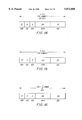
- FIG. 10 illustrates an example of packets for time division duplex
- FIG. 11 illustrates switch time
- FIGS. 12-20 illustrate frequency division duplex examples
- FIG. 21 illustrates adder gates.
- the present invention provides a new and novel spread-spectrum-matched-filter apparatus which can be used as part of a spread-spectrum receiver on a received-spread-spectrum signal.
- the received-spread-spectrum signal is assumed to include a plurality of packets. Each packet has a header followed in time by data.
- the header is generated from spread-spectrum processing, by using techniques well known in the art, a header-symbol-sequence signal with a chip-sequence signal.
- the header-symbol-sequence signal is a predefined sequence of symbols.
- the header-symbol-sequence signal may be a constant value, i.e., just a series of 1-bits or symbols, or a series of 0-bits or symbols, or alternating 1-bits and 0-bits or alternating symbols, a pseudorandom symbol sequence, or other predefined sequence as desired.
- the chip-sequence signal is user defined, and in a usual practice, is used with a header-symbol-sequence signal.
- the data part of the spread-spectrum packet is generated similarly, from techniques well known in the art as used for the header, by spread-spectrum processing a data-symbol-sequence signal with the chip-sequence signal.
- the data-symbol-sequence signal may be derived from data, or an analog signal converted to data, signalling information, or other source of data symbols or bits.
- the chip-sequence signal can be user defined, and preferably is nearly orthogonal to other spread-spectrum channels using the chip-sequence signal, as is well known in the art.
- the spread- spectrum-matched- filter apparatus includes code means, symbol-matched means, frame-matched means, control means, and demodulator means.
- the control means is coupled to the code means and symbol-matched means.
- the frame-matched means is coupled to the output of the symbol-matched means.
- the demodulator means is coupled to the output of the symbol-matched means.
- the code means generates a replica of the chip-sequence signal.
- the replica of the chip-sequence signal is the same sequence as used for generating, at a spread-spectrum transmitter, the received-spread-spectrum signal which arrives at the input of the spread-spectrum-matched-filter apparatus.
- the code means can change, over time, the particular chipping sequence from which the replica of the chip-sequence signal is generated. Accordingly, the spread-spectrum-matched-filter apparatus can be used for a variety of chip-sequence signals as generated by the code means, as might be used in a cellular-spread-spectrum architecture where a receiver might move from one geographical area to another.
- each transmitter within the geographical area of a base station may have a different chipcode sequence.
- the symbol-matched means has a symbol-impulse response.
- symbol is used to denote those means or components which operate on detecting or processing a data or header symbol from the received-spread-spectrum signal.
- the symbol-impulse response can be set from the replica of the chip-sequence signal generated by the code means. Thus, the symbol-impulse response may be set for filtering from the received-spread-spectrum signal, the header and the data-symbol-sequence signal.
- the symbol-matched means With the symbol-impulse response set to the replica of the chip-sequence signal, and with the header portion of the received-spread-spectrum-signal being present at the receiver, the symbol-matched means outputs a despread-header-symbol-sequence signal. Upon detecting the despread-header-symbol sequence, the frame-matched means outputs a high level signal which may be used as a start-data signal. Other uses may be to synchronize the sequence of transmit, switching and receive cycles or to generate a timing signal for any other event that is related in time to the header.
- the symbol-matched means continues to have the symbol-impulse response set from the replica of the chip-sequence signal.
- the symbol-matched means filters the received-spread-spectrum signal. Timing to sample the data portion of the received-spread-spectrum signal is triggered from the start-data signal.
- the symbol-matched means outputs the despread-data-symbol-sequence signal. Accordingly, the symbol-matched means can despread the header and the data portion of the received-spread-spectrum signal.
- the frame-matched means has a frame-impulse response matched to the header-symbol-sequence signal.
- the frame-matched means filters the despread-header-symbol-sequence signal from the symbol-matched means, and generates as a result thereof, a start-data signal when the despread-header-symbol-sequence signal matches the frame-impulse response.
- the frame-matched means may be programmable, i.e., have a programmable frame-impulse response, which might change between different geographical areas.
- the control means controls the setting of the symbol-impulse response of the symbol-matched means.
- the control means can dynamically set the symbol-matched means, by using the replica of the chip-sequence signal generated by the code means, to match the chip-sequence signal embedded in the received-spread-spectrum signal.
- the symbol-matched means may include an in-phase-symbol-matched means and a quadrature-phase-symbol-matched means.
- the in-phase-symbol-matched means has an in-phase-symbol-impulse response which can be set from the replica of the chip-sequence signal generated by the code means.
- the in-phase-symbol-matched means despreads from the received-spread-spectrum signal, an in-phase-component of the header portion of the packet as a despread-in-phase-component of the header-symbol-sequence signal, or an in-phase component of the data portion of the packet as a despread-in-phase component of the data-symbol-sequence signal.
- the quadrature-phase-symbol-matched means has a quadrature-impulse response which can be set from the replica of the chip-sequence signal generated by the code means.
- the quadrature-phase-symbol-matched means despreads from the received-spread spectrum signal a quadrature-phase component of the header portion of the packet as a despread-quadrature-phase component of the header-symbol-sequence signal.
- the quadrature-phase-symbol-matched means when the quadrature-phase-symbol-matched means has the quadrature-symbol-impulse response set from the replica of the chip-sequence signal, the quadrature-phase-symbol-matched means despreads the received-spread-spectrum signal as a quadrature-component of the data portion of the packet as a despread-quadrature-phase component of the despread data-symbol-sequence.
- control means sets the in-phase-symbol-matched means and the quadrature-phase-symbol-matched means matched to detect the chip-sequence signal.
- the in-phase-symbol-matched means and the quadrature-phase-symbol-matched means are matched simultaneously, and preferably are matched to the same chip-sequence signal.
- the frame-matched means may include an in-phase-frame-matched means and a quadrature-phase-frame-matched means.
- the in-phase-frame-matched means has an in-phase-frame-impulse response matched to an in-phase component of the header-symbol-sequence signal.
- an in-phase-start-data signal is generated.
- the quadrature-phase-frame-matched means has a quadrature-phase-frame-impulse response matched to a quadrature-phase component of the header-symbol-sequence signal.
- a quadrature-phase-start-data signal is generated.
- the in-phase-start-data signal and the quadrature-phase-start-data signal are generated simultaneously, buy they may also occur at different times.
- the in-phase-start-data signal and the quadrature-phase-start data signal are combined as the start-data signal.
- Timing for sampling the output of the in-phase-symbol-matched means and the quadrature-phase-symbol-matched means for detecting the data-symbol-sequence signal is triggered, at a time delay, from the start-data signal.
- the time delay may be zero.
- the code means is embodied as a code generator 43
- the symbol-matched means is embodied as an in-phase-symbol-matched filter 35 and a quadrature-phase symbol-matched filter 37
- the frame-matched means is embodied as an in-phase-frame-matched filter 38 and a quadrature-phase-frame-matched filter 39
- the control means is embodied as a controller 46
- the demodulator means is embodied as a demodulator 41.
- the in-phase-symbol-matched filter 35 and the quadrature-phase-symbol-matched filter 37 may be constructed as digital-matched filters, surface-acoustic-wave devices, or as software embedded in a processor or as an application specific integrated circuit (ASIC). Also shown is a voltage-controlled oscillator 45, timing generator 44, diversity combiner 42, frame processor 40, Costas loop 36 or other generic tracking loop, in-phase analog-to-digital converter 33, quadrature-phase analog-to-digital converter 34, in-phase mixer and quadrature-phase mixer 32.
- ASIC application specific integrated circuit
- the in-phase analog-to-digital converter 33 is coupled between in-phase mixer 31 and in-phase-symbol-matched filter 35.
- the quadrature-phase analog-to-digital converter 34 is coupled between the quadrature-phase mixer 32 and the quadrature-phase-symbol-matched filter 37.
- the Costas loop 36 is coupled to the output of the in-phase-symbol-matched filter 35, to the output of the quadrature-phase-symbol-matched filter 37, and to the in-phase mixer 31 and the quadrature-phase mixer 32.
- the in-phase-frame-matched filter 38 is coupled between the in-phase-symbol-matched filter 35 and the frame processor 40 and the demodulator 41.
- the quadrature-phase-frame-matched filter 39 is coupled between the quadrature-phase-symbol-matched filter 37 and the processor 40 and the demodulator 41.
- the code generator 43 is coupled between the timing generator 44 and the in-phase-symbol matched filter 35 and the quadrature-phase-frame-matched filter 37.
- the timing control circuit controls the sampling instant of the analog-to-digital converter timing generator 44 to the in-phase-symbol-matched filter 35 and the quadrature-phase-symbol-matched filter 37.
- the voltage-controlled oscillator 45 is coupled to the timing generator 44 and to the matched-filter controller 46.
- the diversity combiner 42 is coupled to the frame processor 40 and the demodulator 41.
- the controller 46 is coupled to the frame processor 40.
- the in-phase analog-to-digital converter 33 and the quadrature-phase analog-to-digital converter 34 may be embodied as a hard limiter which performs one-bit analog-to-digital conversion, or as an N-bit analog-to-digital converter. Analog-to-digital converters are well known in the art.
- the controller 46 is coupled to the diversity combiner 42, the frame-matched filter 38, the frame-matched filter 39, the demodulator 41, the timing generator 44, the code generator 43, the in-phase-analog-to-digital converter 33, and the quadrature-phase-analog-to-digital converter 34.
- the diversity combiner 42 may only process one signal.
- a received-spread-spectrum signal at the signal input is translated to an intermediate frequency or baseband frequency by in-phase mixer 31 and quadrature-phase mixer 32.
- the received-spread-spectrum signal is assumed to be translated to a baseband frequency.
- the portion of the spread-spectrum receiver which includes low noise amplifiers, automatic-gain-control (AGC) circuits, filters, etc., is well known in the art, and therefore, is not shown.
- the baseband received-spread-spectrum signal is converted to a digital signal by in-phase analog-to-digital converter 33 and quadrature-phase analog-to-digital converter 34.
- AGC automatic-gain-control
- the in-phase-symbol-matched filter 35 has an in-phase-symbol-impulse response which is set by the replica of the chip-sequence signal from code generator 43.
- the in-phase-symbol-matched filter 35 can despread the received-spread-spectrum signal as a despread-in-phase component of the header-symbol-sequence signal or as a despread-in-phase component of the spread-spectrum-processed data-symbol-sequence signal.
- the in-phase-symbol-matched filter 35 outputs either a despread-in-phase component of the header-symbol-sequence signal, or a despread-in-phase component of the spread-spectrum-processed data-symbol-sequence signal as a despread-in-phase-data-symbol-sequence signal.
- the quadrature-phase-symbol-matched filter 37 has a symbol-impulse response which can be set by the replica of the chip-sequence signal generated by the code generator 43.
- the quadrature-phase-symbol-matched filter 37 despreads the received-spread-spectrum signal as a quadrature-phase component of the header-symbol-sequence signal or as a quadrature-phase component of the spread-spectrum-processed data-symbol-sequence signal.
- the output of the quadrature-phase-symbol-matched filter 37 is either a despread-quadrature-phase component of the header-symbol-sequence signal or a despread-quadrature-phase component of the spread-spectrum-processed data-symbol-sequence signal as a despread-quadrature-phase-data-symbol-sequence signal.
- the in-phase-symbol-matched filter 35 and the quadrature-phase-symbol-matched filter 37 are ultimately controlled by the controller 46.
- the controller 46 controls timing and determines at desired timings when the code generator 43 sets the symbol-impulse responses of the in-phase-symbol-matched filter 35 and the quadrature-phase-symbol-matched filter 37 to the respective chip-sequence signal being used in a particular geographic area.
- the controller 46 controls the in-phase signal register 51 and the quadrature-phase signal register 52, which correspond to the in-phase-symbol-matched filter 35 and the quadrature-phase-symbol-matched filter 37, respectively.
- the Costas loop 36 uses the output from the in-phase-symbol-matched filter 35 and the output from the quadrature-phase-symbol-matched filter 37 to generate the cosine signal and sine signal for in-phase mixer 31 and quadrature-phase mixer 32, respectively.
- the spread-spectrum receiver receives packets of header and data, which may arrive as a stream of uninterrupted packets in a frequency division duplex (FDD) application, or as separate packets in a time division duplex (TDD) application.
- FDD frequency division duplex
- TDD time division duplex
- the despread and detected header provides timing and synchronization for data within a respective packet.
- the output is a despread-header-symbol-sequence signal.
- An example of a signal outputted as a despread-header-symbol-sequence signal is illustrated in FIG. 3.
- the despread-header-symbol-sequence signal is passed through in-phase-frame-matched filter 38 and quadrature-phase-frame-matched filter 39.
- the in-phase-frame-matched filter 38 has an in-phase-frame-impulse response matched to the in-phase component of the header-symbol-sequence signal, and accordingly, generates an in-phase-start-data signal when the in-phase component of the despread-header-symbol-sequence signal matches the in-phase-frame-impulse response.
- the quadrature-phase-frame-matched filter 39 has a quadrature-phase-frame-impulse response matched to a quadrature-phase component of the header-symbol-sequence signal.
- the quadrature-phase-frame-matched filter 37 When the despread-header-symbol-sequence signal from the quadrature-phase-symbol-matched filter 37 matches the quadrature-phase-frame-impulse response of the quadrature-phase-matched filter 37, then the quadrature-phase-frame-matched filter outputs a quadrature-phase-start-data signal.
- An example of a signal outputted from the frame-matched filter is illustrated in FIG. 4.
- the large spike's, i.e., large signal levels, are the start-data signal referred to herein. These spikes or start-data signals serve as timing references to synchronize timing, as disclosed herein.
- the in-phase-start-data signal and the quadrature-phase-start-data signal are demodulated by demodulator 41, and can be used as an initial timing signal for controlling when the diversity combiner 42 combines the output from the demodulator 41 for the respective signals from in-phase-symbol-matched filter 35 and the quadrature-phase-symbol-matched filter 37.
- the in-phase-start-data signal and the quadrature-phase-start-data signal can be processed by frame processor 40 to trigger a timing signal, i.e., the start-data signal, to the controller 46 which actuates the timing for when to sample the outputs of the in-phase-symbol-matched filter 35 and the quadrature-phase-symbol-matched filter 37, for detecting the data-symbol-sequence signal.
- a timing signal i.e., the start-data signal
- the in-phase-symbol-matched filter 35 and the quadrature-phase-symbol-matched filter 37 have their respective in-phase-symbol-impulse response and quadrature-phase-symbol-impulse response determined, under the control of the controller 46, such that they are matched to the chip-sequence signal within 6.4 microseconds (64 chips at 10 Mchips/sec).
- current designs have these respective symbol-matched filters loaded within 12.8 microseconds, for a system operating at 100 MHz, with each of the in-phase-symbol-matched filter 35 and the quadrature-phase-symbol-matched filter 37 having a 256 stage shift register (256 chips at 20 Mchips/sec).
- the demodulator 41 can be implemented using coherent demodulation, or alternatively using noncoherent demodulation.
- the diversity combiner 42 combines in a variety of ways, such as maximum likelihood, straight combining, addition, or the demodulated outputs from the in-phase-symbol-matched filter 35 and the quadrature-phase-symbol-matched filter 37 as demodulated through demodulator 41.
- FIG. 2 illustrates the matched filter using the time sharing of the multiplier array and adder tree. Shown in FIG. 2 are in-phase-signal register 51, quadrature-phase-signal register 52, reference-signal register 53, multiplier array 54, adder tree 55, data register 56, and controller 46. As shown, the dotted lines indicate that the controller 46 provides the necessary controlling of the in-phase-signal register 51, the quadrature-phase-signal register 52, the reference-signal reference 53 and the data register 56. The solid lines indicate the signal flow from the in-phase-signal register 51, the quadrature-phase-signal register 52, the reference-signal register 53 through the multiplexer 57. The in-phase-signal register 51 and the quadrature-phase-signal register 52 are coupled through multiplexer 57 to multiplier array 54 to adder tree 55 to data register 56. The data register 56 has an in-phase output and quadrature-phase output.
- the present invention also includes a method which uses a symbol-matched filter and a frame-matched filter with a spread-spectrum receiver on a received-spread-spectrum signal.
- the received-spread-spectrum signal is assumed to have a plurality of packets, with each packet including a header and data portion.
- the header is generated from spread-spectrum processing a header-symbol-sequence signal with a chip-sequence signal.
- the data portion of the packet is generated from spread-spectrum processing a data-symbol-sequence signal with the chip-sequence signal.
- the method comprises the steps of generating a replica of the chip-sequence signal.
- the method programs the symbol-matched filter with the replica of the chip-sequence signal to set the symbol-matched filter to have a symbol-impulse response matched to the chip-sequence signal.
- the method despreads the header portion of the packet from the received-spread-spectrum signal as a despread header-symbol-sequence signal.
- the frame-matched filter has a frame-impulse response matched to the header-symbol-sequence signal.
- the method therefore uses the frame-matched filter to filter the despread header-symbol-sequence signal.
- the method thereafter generates from the filtered despread-header-symbol-sequence signal, the data-start signal in response to the despread-header-symbol-sequence signal matching the frame-impulse response of the frame-matched filter.
- the method also generates at a time delay from the data-start signal, a data-control signal.
- the time delay may be zero.
- the method programs the frame-matched filter with the replica of the data-chip-sequence signal so that the frame-matched filter has the frame-impulse response matched to the data-symbol-sequence signal.
- the method thereby despreads, while the frame-matched filter is matched to the data-symbol-sequence signal, the data-spread-spectrum channel from the received-spread-spectrum signal as a despread-data-symbol-sequence signal.
- the method as described herein may be extended to in-phase and quadrature-phase components of a received-spread-spectrum signal.
- the method would have the step of despreading the header portion of the packet from the received-spread-spectrum signal including the steps of despreading, from the received-spread-spectrum signal, the in-phase component of the header as a despread in-phase component of the header-symbol-sequence signal, and despreading, from the received-spread-spectrum signal, the quadrature-phase component of the header as a despread-quadrature-phase component of the header-symbol-sequence signal.
- the in-phase component and the quadrature-phase component of the received-spread-spectrum signal can be despread as in-phase components and quadrature-phase components of the data-symbol-sequence signal.
- the method would include despreading, from the received-spread-spectrum signal, an in-phase component of the data portion of the packet as a despread-in-phase component of the data-symbol-sequence signal.
- the method would also include despreading a quadrature-phase component of the data portion of the packet as a despread-quadrature-phase component of the data-symbol-sequence signal.
- the method can also include generating an in-phase-start-data signal and a quadrature-phase-start-data signal, in response to the in-phase component and the quadrature-phase component of the despread header-symbol-sequence signal matching the in-phase-frame-impulse response and the quadrature-phase-frame-impulse response, respectively.
- the in-phase-symbol-matched filter 35 and the quadrature-phase-symbol-matched filter 37 are loaded with M local sequence symbols, i.e., the replica of the chip-sequence signal.
- This large output does not require that a synchronization process be successfully completed a priori or that additional circuits dedicated to the acquisition process be employed and it achieves code synchronization in the shortest possible time to acquire the incoming spreading chip-sequence signal.
- This has the advantage of lower implementation cost, lower physical volume, reduced power consumption, more rapid implementation and much better performance as measured by the time required to achieve code synchronization.
- the presence of a strong signal level output indicates that at that specific moment in time M incoming signal symbols and the M symbols of the local spreading code, i.e., chip-sequence signal, loaded in the in-phase-symbol-matched filter 35 and the quadrature-phase-symbol-matched filter 37 are in alignment.
- M incoming signal symbols and the M symbols of the local spreading code i.e., chip-sequence signal
- the in-phase-symbol-matched filter 35 and the quadrature-phase-symbol-matched filter 37 be fully loaded with the next M symbols of the local spreading code, i.e., the chip-sequence signal, at any time prior to the arrival of the next M incoming signal symbols at the in-phase-symbol-matched filter 35 and the quadrature-phase-symbol-matched filter 37.
- M which denotes the size of the respective symbol-matched filter as measured in number of signal samples, is much larger than any value on the order of one; in an example embodiment, M is on the order of 250. Because M is much larger than one of the circuits required to implement the code, phase synchronization functions are much easier to design and implement. This has the advantage of lower implementation cost, lower physical volume, reduced power consumption, more rapid implementation and inherently better performance.
- the in-phase-symbol-matched filter 35 and the quadrature-phase-programmable filter 37 identify, characterize and extract the information which arrives through all available channels, or paths, intrinsically, without any additional and parallel signal processing paths.
- the outputs due to the signals' propagation through different channels are output by the in-phase-symbol-matched filter 35 and the quadrature-phase-symbol-matched filter 37 offset in time.
- the reception and separation of the signals propagating through different channels does not require any additional circuits and the individual signals, which are now separate in time, can be easily individually manipulated and combined in optimum ways such that the matched filter receiver attains the performance of an L-diversity system.
- a receiver capable of identifying, separating and combining large numbers (L) of signal replicas propagating through different channels is a time diversity receiver and is commonly called a RAKE receiver.
- the RAKE receiver structure can be implemented using the matched filter without the excessive complexity incurred by alternative system implementations.
- the in-phase-symbol-matched filter 35 and the quadrature-phase-symbol-matched filter 37 implementation of the heart of the diversity processing system has the advantage of lower implementation cost, lower physical volume, reduced power consumption, more rapid implementation, less complex control and better performance.
- the symbol-matched-filter-based demodulator as described herein utilizes only one such set of circuits and, using information which is intrinsically generated, can then coherently demodulate any number of signal replicas that arrive via separate propagation paths.
- the mechanism by which this is accomplished is to employ one conventional phase tracking circuit, e.g., phase-locked loop (PLLs), Costas loop, or n th power loop, in order to establish a temporarily stable phase reference and to then extract the phase offset of each individual signal with respect to that phase reference.
- the incoming signal is first downconverted non-coherently to some frequency, including the 0 Hz frequency (DC).
- the in-phase and quadrature-phase channel outputs are read from the in-phase-symbol-matched filter 35 and the quadrature-phase-symbol-matched filter 37, respectively.
- the phase offset of the carrier signal is contained in the relative amplitudes of the in-phase and quadrature-phase outputs which are then used directly to demodulate the received data signal.
- the phase estimate on the individual propagation paths can be improved by further matched filtering to demodulate the signal with performance equal to or better than that obtained using conventional coherent demodulators but without the added complexity introduced by conventional coherent demodulators. Therefore the symbol-matched filter-based implementation has the advantage of much lower complexity, lower implementation cost, lower physical volume, reduced power consumption, more rapid implementation and better performance.
- a set of multipliers and the associated adder tree may be eliminated.
- each multiplexer may serve to connect to the multiplier/adder tree structure either the in-phase or quadrature-phase signal registers.
- This implementation adds the complexity of two multiplexers and reduces the complexity associated with a set of multipliers and an adder tree for a significant net reduction in complexity.
- the symbol-matched filter is a digital signal processor, the output of which is of interest only at that instant in time when the portion of interest of the incoming signal is fully loaded and is of no interest at any other time.
- the size of the symbol-matched filters is approximately 64 or 256 stages, requiring 64 or 256 clock cycles, respectively, to load the input samples of the received-spread-spectrum signal.
- the output of the symbol-matched filter is of interest only for one or two clock cycles and is of no interest for the rest of the approximately 248 clock cycles. Thus the circuit can be reused during these 248 clock cycles.
- the symbol-matched filters are loaded with the reference corresponding to the first signal.
- the output due to the first signal occur during the 50 th and 51 st clock cycle.
- the symbol-matched filters are loaded with the reference corresponding to the third signal.
- the output to the third signal will occur during the 150 th and 151 st clock cycle.
- the symbol-matched filters are loaded with the reference corresponding to the fifth signal.
- the output due to the fifth signal will occur during the 250 th and 251 st clock cycle.
- the cycle then repeats itself for the next output due to the first, second, third, fourth and fifth signals using only one matched filter.
- the complexity of and size of implementation is reduced by 80% while the signal processing benefits remain constant.
- the matched filter is preferred since it can provide significantly faster acquisition than the standard serial-search technique. For example, if the chip rate were f c and the number of chips that must be searched before accepting or discarding a hypothesis is N and the code length is L, then the "worst-case" acquisition time for serial search is LN/f c while the equivalent matched-filter acquisition time is L/f c .
- N is between 1000 and 10,000, so that for a matched filter of length N a significant savings can accrue by using a matched filter.
- One aspect of this invention is a novel procedure to implement the matched filter.
- Another aspect of this invention is to not employ a transmitted reference but to achieve "coherent" detection by employing frequency locked and phase locked circuits which do not require a large number of gates.
- the matched filter of the present invention is divided into two or more matched filter sections.
- the present invention employs two sections.
- the size of the symbol-matched filter determines the number of simultaneous users. It has been found experimentally that the number of simultaneous signals in the DS-CDMA system is approximately N s /2, when using the cascaded matched filter approach diagrammed in FIGS. 1 and 2.
- the symbol-matched filter output is noisy and a casual observation does not indicate the instant at which a match occurs when there are many signals present simultaneously. This is illustrated in FIG. 3.
- the preferred approach to finding the correct time instant is to measure all 256 symbol-matched filter outputs and record the largest. This procedure is then repeated until a given K number of measurements indicate the same instant, as illustrated in FIG. 5.
- time slot J After time slot J is selected, the choice is verified using the frame-matched filter.
- the matched filter has a register and adders, as shown in FIG. 6.
- row 1 has 128 adders; row 2 has 64; row 3 has 32; etc.
- a preferred approach is to sample once per chip.
- the sampling rate is f c
- the problem with this approach is that the sampling may not occur at the peak of a chip, as illustrated in FIG. 7. This problem is compounded by the fact that the local receiving chip-clock crystal might differ slightly from the chip-clock crystal in the transmitter. As a result of clock mismatch, the sampling instant slides across the chip.
- one aspect of this invention is to ensure that the sampling clock continually samples at or near the peak of each chip.
- Second the present invention averages the outputs of the symbol-matched filter N F times, delays the chip clock by a fraction of a chip, preferably 1/8 chip, and averages the output of the symbol-matched filter, N F times. Then the chip clock is advanced by 1/8 chip and again the symbol-matched filter output is averaged N F times. The timing selected is that which yields the largest output. This process is continually repeated, as illustrated in FIG. 8 and 9.
- the transmitter and receiver RF crystal frequencies usually differ. Differences of 20 kHz are possible.
- the incoming signal undergoes a Doppler shift due to the fact that the transmitter and/or receiver may be in motion.
- the Doppler shift usually is not larger than 300 Hz at a center frequency of 2 GHz.
- time-division duplex TDD
- frequency-division duplex FDD
- the time-division duplex can be used for the CP ASIC.
- the frequency-division duplex can be used for the WLL and PCS ASIC since higher data rates are needed for WLL and PCS applications. Using time-division duplex effectively doubles the data rate.
- FIG. 10 illustrates an example of packets for time division duplex.
- Dead time is used for switching from transmit (TX) mode to receive (RCVE) mode, and vice versa as illustrated in FIG. 11.
- f c 10.368 MHz (required by adaptive delta pulse code modulation (ADPCM)).
- ADPCM adaptive delta pulse code modulation
- the receive packet duration is equal to the transmit packet duration.
- the switch (SW) times, FIG. 11, are needed to switch the RF from the TX mode to the RCVE mode and vice versa. Approximately 50 microseconds is needed.
- An embodiment of the present invention uses 8 symbols.
- FDD packet An example of a FDD packet is
- phase varies due to Doppler or oscillator offset then if the phase variation were small between adjacent bits, differential demodulation can be used.
- b(t) can represent the differentially decoded data stream. Differential encoding must be used. If there were no phase variation, then b(t) has twice the error of d(t); see Taub and Schilling, PRINCIPLES OF COMMUNICATION SYSTEMS.
- frequency and phase are locked to the best of ability, and differential decoding is used to compensate for estimation inaccuracies. If the frequency locking were perfect so that the phase were consistent, then coherent detection occurs and the error rate increases by a factor of two.
- 1 bit is equal to 2 or more symbols. In that case the symbols are added prior to differential decoding. High data rates use less than 1 symbol.
Abstract
Description
______________________________________
The TX packet
______________________________________
15      symbols =
                 header which is detected by a 15-stage
                 frame-matched filter
1-2     symbols =
                 APC
1-2     symbols =
                 signaling
32      symbols =
                 voice (assuming 32 kb/s is used)
1       symbols =
                 do not care, used to compensate
                 for propagation delay
21      symbols =
                 CRC
73      symbols
______________________________________
______________________________________ Timing ______________________________________ 73symbols TX 73 symbols RCVE 8SW 8 SW 162 symbols/frame ______________________________________
______________________________________ 32 267 + 52CRC 324 total ______________________________________
______________________________________ 288 +32 320 + 4CRC symbols 324 ______________________________________
______________________________________ 272 +32 304 +20CRC symbols 324 ______________________________________
______________________________________ 264 +32 296 +28CRC symbols 324 ______________________________________
______________________________________ 156 +32 188 +136CRC symbols 324 ______________________________________
______________________________________ 154 +32 186 +138CRC symbols 324 ______________________________________
______________________________________ 194 +32 226 + 98CRC symbols 324 ______________________________________
______________________________________ 193 +32 225 + 99CRC symbols 324 ______________________________________
______________________________________ 256 32 +0.5 288.5 + 35.5CRC symbols 324 ______________________________________
Claims (5)
Priority Applications (2)
| Application Number | Priority Date | Filing Date | Title |
|---|---|---|---|
| US08/564,007 US5872808A (en) | 1995-05-25 | 1995-11-29 | Apparatus and method for synchronization of direct sequence CDMA signals |
| US09/182,054 US6393049B1 (en) | 1995-05-25 | 1998-10-29 | Two-stage synchronization of spread-spectrum signals |
Applications Claiming Priority (2)
| Application Number | Priority Date | Filing Date | Title |
|---|---|---|---|
| US08/450,312 US5627855A (en) | 1995-05-25 | 1995-05-25 | Programmable two-part matched filter for spread spectrum |
| US08/564,007 US5872808A (en) | 1995-05-25 | 1995-11-29 | Apparatus and method for synchronization of direct sequence CDMA signals |
Related Parent Applications (2)
| Application Number | Title | Priority Date | Filing Date |
|---|---|---|---|
| US08/450,312 Continuation-In-Part US5627855A (en) | 1995-05-25 | 1995-05-25 | Programmable two-part matched filter for spread spectrum |
| US08/450,312 Continuation US5627855A (en) | 1995-05-25 | 1995-05-25 | Programmable two-part matched filter for spread spectrum |
Related Child Applications (1)
| Application Number | Title | Priority Date | Filing Date |
|---|---|---|---|
| US09/182,054 Continuation US6393049B1 (en) | 1995-05-25 | 1998-10-29 | Two-stage synchronization of spread-spectrum signals |
Publications (1)
| Publication Number | Publication Date |
|---|---|
| US5872808A true US5872808A (en) | 1999-02-16 |
Family
ID=23787593
Family Applications (6)
| Application Number | Title | Priority Date | Filing Date |
|---|---|---|---|
| US08/450,312 Expired - Fee Related US5627855A (en) | 1995-05-25 | 1995-05-25 | Programmable two-part matched filter for spread spectrum |
| US08/564,007 Expired - Fee Related US5872808A (en) | 1995-05-25 | 1995-11-29 | Apparatus and method for synchronization of direct sequence CDMA signals |
| US08/596,037 Expired - Lifetime US5764691A (en) | 1995-05-25 | 1996-02-06 | Intelligent power management for a programmable matched filter |
| US08/821,003 Expired - Fee Related US5802102A (en) | 1995-05-25 | 1997-03-20 | Programmable two-part matched filter for spread spectrum |
| US09/090,834 Expired - Lifetime US5999562A (en) | 1995-05-25 | 1998-06-04 | Intelligent power management for a programmable matched filter |
| US09/182,054 Expired - Lifetime US6393049B1 (en) | 1995-05-25 | 1998-10-29 | Two-stage synchronization of spread-spectrum signals |
Family Applications Before (1)
| Application Number | Title | Priority Date | Filing Date |
|---|---|---|---|
| US08/450,312 Expired - Fee Related US5627855A (en) | 1995-05-25 | 1995-05-25 | Programmable two-part matched filter for spread spectrum |
Family Applications After (4)
| Application Number | Title | Priority Date | Filing Date |
|---|---|---|---|
| US08/596,037 Expired - Lifetime US5764691A (en) | 1995-05-25 | 1996-02-06 | Intelligent power management for a programmable matched filter |
| US08/821,003 Expired - Fee Related US5802102A (en) | 1995-05-25 | 1997-03-20 | Programmable two-part matched filter for spread spectrum |
| US09/090,834 Expired - Lifetime US5999562A (en) | 1995-05-25 | 1998-06-04 | Intelligent power management for a programmable matched filter |
| US09/182,054 Expired - Lifetime US6393049B1 (en) | 1995-05-25 | 1998-10-29 | Two-stage synchronization of spread-spectrum signals |
Country Status (7)
| Country | Link |
|---|---|
| US (6) | US5627855A (en) |
| EP (1) | EP0872025A4 (en) |
| JP (1) | JPH11505983A (en) |
| KR (1) | KR19990021898A (en) |
| AU (1) | AU5918696A (en) |
| CA (1) | CA2219200A1 (en) |
| WO (1) | WO1996037968A1 (en) |
Cited By (17)
| Publication number | Priority date | Publication date | Assignee | Title |
|---|---|---|---|---|
| WO2000059123A1 (en) * | 1999-03-31 | 2000-10-05 | Qualcomm Incorporated | Programmable matched filter searcher |
| WO2000067387A1 (en) * | 1999-05-04 | 2000-11-09 | Koninklijke Philips Electronics N.V. | Method for determining the start of a pulse in a spread spectrum system |
| US6151313A (en) * | 1997-06-06 | 2000-11-21 | Aloha Networks, Inc. | Baseband phase estimation technique for demodulation of overlapping packets |
| US6208632B1 (en) * | 1998-01-29 | 2001-03-27 | Sharp Laboratories Of America | System and method for CDMA channel estimation |
| EP1139576A2 (en) * | 2000-03-06 | 2001-10-04 | Texas Instruments Incorporated | Co-processor for correlation in CDMA receiver |
| US6304592B1 (en) * | 1997-04-07 | 2001-10-16 | Golden Bridge Technology, Inc. | Coherent detection using matched filter enhanced spread spectrum demodulation |
| US6370182B2 (en) | 2000-02-10 | 2002-04-09 | Itt Manufacturing Enterprises, Inc. | Integrated beamforming/rake/mud CDMA receiver architecture |
| US6421372B1 (en) | 1999-11-10 | 2002-07-16 | Itt Manufacturing Enterprises, Inc. | Sequential-acquisition, multi-band, multi-channel, matched filter |
| US6448926B1 (en) | 1993-11-19 | 2002-09-10 | Itt Manufacturing Enterprises, Inc. | Multi-band, multi-function integrated transceiver |
| US6539009B1 (en) * | 1997-12-26 | 2003-03-25 | Yozan, Inc. | Signal reception apparatus for DS-CDMA cellular system |
| KR100393106B1 (en) * | 2000-12-19 | 2003-07-31 | 엘지전자 주식회사 | Acquisition device and method for early synchronization in receiver of code devision multiple access system |
| US6754257B1 (en) * | 1998-09-30 | 2004-06-22 | Nec Corporation | Frame timing synchronization method |
| US6771688B1 (en) | 2000-09-19 | 2004-08-03 | Lucent Technologies Inc. | Segmented architecture for multiple sequence detection and identification in fading channels |
| US8391223B2 (en) | 2007-08-01 | 2013-03-05 | Nokia Siemens Networks Oy | Resource allocation |
| US20140315507A1 (en) * | 2011-12-22 | 2014-10-23 | Anite Finland Oy | Apparatus and Method for Detecting Co-Channels Signals |
| US9737365B2 (en) | 2003-05-23 | 2017-08-22 | Intuitive Surgical Operations, Inc. | Tool with articulation lock |
| US11732518B2 (en) | 2018-10-30 | 2023-08-22 | Whirlpool Corporation | Door alignment mechanism |
Families Citing this family (91)
| Publication number | Priority date | Publication date | Assignee | Title |
|---|---|---|---|---|
| JP3581448B2 (en) * | 1994-10-21 | 2004-10-27 | キヤノン株式会社 | Spread spectrum communication equipment |
| US5627855A (en) * | 1995-05-25 | 1997-05-06 | Golden Bridge Technology, Inc. | Programmable two-part matched filter for spread spectrum |
| US6697350B2 (en) | 1995-06-30 | 2004-02-24 | Interdigital Technology Corporation | Adaptive vector correlator for spread-spectrum communications |
| US7020111B2 (en) | 1996-06-27 | 2006-03-28 | Interdigital Technology Corporation | System for using rapid acquisition spreading codes for spread-spectrum communications |
| US6831905B1 (en) * | 1995-06-30 | 2004-12-14 | Interdigital Technology Corporation | Spread spectrum system assigning information signals to message-code signals |
| ZA965340B (en) | 1995-06-30 | 1997-01-27 | Interdigital Tech Corp | Code division multiple access (cdma) communication system |
| US6816473B2 (en) | 1995-06-30 | 2004-11-09 | Interdigital Technology Corporation | Method for adaptive forward power control for spread-spectrum communications |
| US7123600B2 (en) * | 1995-06-30 | 2006-10-17 | Interdigital Technology Corporation | Initial power control for spread-spectrum communications |
| US7929498B2 (en) | 1995-06-30 | 2011-04-19 | Interdigital Technology Corporation | Adaptive forward power control and adaptive reverse power control for spread-spectrum communications |
| US6788662B2 (en) | 1995-06-30 | 2004-09-07 | Interdigital Technology Corporation | Method for adaptive reverse power control for spread-spectrum communications |
| US6885652B1 (en) | 1995-06-30 | 2005-04-26 | Interdigital Technology Corporation | Code division multiple access (CDMA) communication system |
| JPH09321667A (en) * | 1996-05-29 | 1997-12-12 | Yozan:Kk | Receiver for cdma communication system |
| US5862133A (en) * | 1996-08-02 | 1999-01-19 | Golden Bridge Technology | Packet-switched spread-spectrum system |
| US5715276A (en) * | 1996-08-22 | 1998-02-03 | Golden Bridge Technology, Inc. | Symbol-matched filter having a low silicon and power requirement |
| US5950131A (en) * | 1996-10-29 | 1999-09-07 | Motorola, Inc. | Method and apparatus for fast pilot channel acquisition using a matched filter in a CDMA radiotelephone |
| US6005887A (en) * | 1996-11-14 | 1999-12-21 | Ericcsson, Inc. | Despreading of direct sequence spread spectrum communications signals |
| JP3317866B2 (en) * | 1996-12-20 | 2002-08-26 | 富士通株式会社 | Spread spectrum communication system |
| US5943375A (en) * | 1997-02-06 | 1999-08-24 | At&T Wireless Services Inc. | Method to indicate synchronization lock of a remote station with a base station |
| US5914981A (en) * | 1997-02-24 | 1999-06-22 | At&T Wireless Services Inc. | Method to indicate synchronization lock of a remote station with a base station for a discrete multitone spread spectrum communications system |
| WO1998035458A1 (en) * | 1997-02-06 | 1998-08-13 | At & T Wireless Services, Inc. | Method of synchronizing a remote station with a base station in a discrete multitone spread spectrum communications system |
| US5956369A (en) * | 1997-02-24 | 1999-09-21 | Golden Bridge Technology, Inc. | Spread spectrum multipath combining subsystem and method |
| US6349110B1 (en) * | 1997-02-24 | 2002-02-19 | Golden Bridge Technology, Inc. | Subsystem and method for combining spread-spectrum multipath signals |
| US6898197B1 (en) * | 1997-02-28 | 2005-05-24 | Interdigital Technology Corporation | Geolocation of a mobile terminal in a CDMA communication system |
| GB9707861D0 (en) * | 1997-04-18 | 1997-06-04 | Certicom Corp | Arithmetic processor |
| US7027490B2 (en) | 1997-06-11 | 2006-04-11 | Intel Corporation | Method and apparatus for reducing spread spectrum noise |
| US6628701B2 (en) | 1997-06-11 | 2003-09-30 | Intel Corporation | Method and apparatus for reducing spread spectrum noise |
| JP3751419B2 (en) * | 1997-06-16 | 2006-03-01 | 松下電器産業株式会社 | Matched filter and synchronization method |
| JP2002198932A (en) | 1997-09-30 | 2002-07-12 | Matsushita Electric Ind Co Ltd | Correlation detection method and matched filter |
| US5894494A (en) * | 1997-10-29 | 1999-04-13 | Golden Bridge Technology, Inc. | Parallel correlator architecture for synchronizing direct sequence spread-spectrum signals |
| US6567483B1 (en) * | 1997-11-11 | 2003-05-20 | Ericsson, Inc. | Matched filter using time-multiplexed precombinations |
| JP3856261B2 (en) * | 1998-03-18 | 2006-12-13 | ソニー株式会社 | Synchronous detection device |
| JP3484072B2 (en) * | 1998-04-14 | 2004-01-06 | 株式会社日立国際電気 | Despreading circuit |
| US6130906A (en) * | 1998-05-22 | 2000-10-10 | Golden Bridge Technology, Inc. | Parallel code matched filter |
| SE9802109D0 (en) * | 1998-06-12 | 1998-06-12 | Ericsson Telefon Ab L M | One-bit correlator rake receiver |
| US6041073A (en) * | 1998-09-18 | 2000-03-21 | Golden Bridge Technology, Inc. | Multi-clock matched filter for receiving signals with multipath |
| US6493405B1 (en) | 1999-03-02 | 2002-12-10 | Harris Corporation | Correlator having enhanced memory for reference and input data |
| US6038271A (en) * | 1999-03-02 | 2000-03-14 | Harris Corporation | Correlator with cascade data paths to facilitate expansion of correlator length |
| US6438182B1 (en) | 1999-03-02 | 2002-08-20 | Harris Corporation | Correlator with serial-parallel partition |
| US6704348B2 (en) | 2001-05-18 | 2004-03-09 | Global Locate, Inc. | Method and apparatus for computing signal correlation at multiple resolutions |
| US6717930B1 (en) * | 2000-05-22 | 2004-04-06 | Interdigital Technology Corporation | Cell search procedure for time division duplex communication systems using code division multiple access |
| CN100481747C (en) * | 1999-05-28 | 2009-04-22 | 交互数字技术公司 | Cell search procedure for time division duplex communication systems using code division multiple access |
| US6657979B1 (en) * | 1999-08-23 | 2003-12-02 | Motorola, Inc. | Reduced power consumption multiplexer using self-decoding power down logic |
| KR100314113B1 (en) * | 1999-08-25 | 2001-11-15 | 구자홍 | matched filter and filtering method, apparatus and method for receiving plural digital broadcast using digital filter |
| JP3296341B2 (en) * | 1999-09-20 | 2002-06-24 | 日本電気株式会社 | Correlator |
| US6760366B1 (en) | 1999-11-29 | 2004-07-06 | Qualcomm Incorporated | Method and apparatus for pilot search using a matched filter |
| JP3937380B2 (en) * | 1999-12-14 | 2007-06-27 | 富士通株式会社 | Path search circuit |
| US6324210B1 (en) | 1999-12-17 | 2001-11-27 | Golden Bridge Technology Incorporated | Sliding matched filter with flexible hardware complexity |
| JP2001251220A (en) * | 1999-12-27 | 2001-09-14 | Sanyo Electric Co Ltd | Digital matched filter and mobile wireless terminal using the digital matched filter |
| WO2001050616A1 (en) | 1999-12-30 | 2001-07-12 | Morphics Technology, Inc. | A configurable all-digital coherent demodulator system for spread spectrum applications |
| US20020064212A1 (en) * | 2001-02-21 | 2002-05-30 | Daoben Li | Code-division-multiple-access receiver with zero correlation window |
| US20030067964A1 (en) * | 2000-02-10 | 2003-04-10 | Daoben Li | Code-division-multiple-access system using zero correlation window |
| US6842480B1 (en) | 2000-02-28 | 2005-01-11 | Golden Bridge Technology Incorporated | Programmable matched filter bank |
| US6496104B2 (en) | 2000-03-15 | 2002-12-17 | Current Technologies, L.L.C. | System and method for communication via power lines using ultra-short pulses |
| US6998962B2 (en) | 2000-04-14 | 2006-02-14 | Current Technologies, Llc | Power line communication apparatus and method of using the same |
| US6947721B2 (en) * | 2000-05-15 | 2005-09-20 | Texas Instruments Incorporated | Wireless communications with transceiver-integrated frequency shift control and power control |
| US8576754B2 (en) | 2000-05-22 | 2013-11-05 | Interdigital Technology Corporation | TDD base station for code group synchronization |
| US6801569B1 (en) | 2000-06-22 | 2004-10-05 | Golden Bridge Technology Inc. | Digital matched filter bank for othogonal signal set |
| EP1175019B1 (en) * | 2000-07-21 | 2004-03-17 | STMicroelectronics N.V. | RAKE receiver for a CDMA system, in particular incorporated in a cellular mobile phone |
| WO2002033859A1 (en) * | 2000-10-17 | 2002-04-25 | Aloha Networks, Inc. | Synchronization and bit detection in a single spreading sequence sama receiver |
| EP1371219A4 (en) * | 2001-02-14 | 2006-06-21 | Current Tech Llc | Data communication over a power line |
| US7209461B2 (en) * | 2001-05-09 | 2007-04-24 | Qualcomm Incorporated | Method and apparatus for chip-rate processing in a CDMA system |
| US7006556B2 (en) | 2001-05-18 | 2006-02-28 | Global Locate, Inc. | Method and apparatus for performing signal correlation at multiple resolutions to mitigate multipath interference |
| US7190712B2 (en) * | 2001-05-18 | 2007-03-13 | Global Locate, Inc | Method and apparatus for performing signal correlation |
| US6891880B2 (en) * | 2001-05-18 | 2005-05-10 | Global Locate, Inc. | Method and apparatus for performing signal correlation |
| US7995682B2 (en) | 2001-05-18 | 2011-08-09 | Broadcom Corporation | Method and apparatus for performing signal processing using historical correlation data |
| US7567636B2 (en) * | 2001-05-18 | 2009-07-28 | Global Locate, Inc. | Method and apparatus for performing signal correlation using historical correlation data |
| US7769076B2 (en) | 2001-05-18 | 2010-08-03 | Broadcom Corporation | Method and apparatus for performing frequency synchronization |
| US6819707B2 (en) * | 2001-05-18 | 2004-11-16 | Global Locate, Inc. | Method and apparatus for performing signal correlation using historical correlation data |
| GB2381714B (en) * | 2001-11-02 | 2004-07-07 | Toshiba Res Europ Ltd | Receiver processing system |
| JP3820981B2 (en) * | 2001-12-20 | 2006-09-13 | 日本電気株式会社 | RADIO COMMUNICATION SYSTEM AND METHOD FOR IDENTIFYING TIME OF DESTINATION PORTABLE TERMINAL IN SOURCE PORTABLE TERMINAL |
| US7194021B2 (en) * | 2002-04-15 | 2007-03-20 | Stmicroelectronics, Inc. | Digital matched filter |
| US7042925B2 (en) * | 2003-02-24 | 2006-05-09 | Thomson Licensing | Correlation detection improvement by averaging spread spectrum signals |
| DE102004005456A1 (en) * | 2004-02-04 | 2005-08-25 | Robert Bosch Gmbh | Fuel injector with direct-acting injection valve member |
| US8108429B2 (en) | 2004-05-07 | 2012-01-31 | Quest Software, Inc. | System for moving real-time data events across a plurality of devices in a network for simultaneous data protection, replication, and access services |
| US7565661B2 (en) | 2004-05-10 | 2009-07-21 | Siew Yong Sim-Tang | Method and system for real-time event journaling to provide enterprise data services |
| US7680834B1 (en) | 2004-06-08 | 2010-03-16 | Bakbone Software, Inc. | Method and system for no downtime resychronization for real-time, continuous data protection |
| US7394878B2 (en) * | 2004-06-28 | 2008-07-01 | X-Cyte, Inc. | Digital frequency determining apparatus and methods using matched filters |
| US7979404B2 (en) | 2004-09-17 | 2011-07-12 | Quest Software, Inc. | Extracting data changes and storing data history to allow for instantaneous access to and reconstruction of any point-in-time data |
| US7904913B2 (en) | 2004-11-02 | 2011-03-08 | Bakbone Software, Inc. | Management interface for a system that provides automated, real-time, continuous data protection |
| US7937510B1 (en) * | 2005-02-01 | 2011-05-03 | Altera Corporation | Lempel Ziv compression architecture |
| US7689602B1 (en) | 2005-07-20 | 2010-03-30 | Bakbone Software, Inc. | Method of creating hierarchical indices for a distributed object system |
| US7788521B1 (en) | 2005-07-20 | 2010-08-31 | Bakbone Software, Inc. | Method and system for virtual on-demand recovery for real-time, continuous data protection |
| US7283937B2 (en) * | 2005-12-21 | 2007-10-16 | Palo Alto Research Center Incorporated | Method, apparatus, and program product for distinguishing valid data from noise data in a data set |
| KR100859833B1 (en) * | 2006-07-20 | 2008-09-23 | 주식회사 하이닉스반도체 | Semiconductor memory device |
| US20080056338A1 (en) * | 2006-08-28 | 2008-03-06 | David Stanley Yaney | Power Line Communication Device and Method with Frequency Shifted Modem |
| US8131723B2 (en) | 2007-03-30 | 2012-03-06 | Quest Software, Inc. | Recovering a file system to any point-in-time in the past with guaranteed structure, content consistency and integrity |
| US8364648B1 (en) | 2007-04-09 | 2013-01-29 | Quest Software, Inc. | Recovering a database to any point-in-time in the past with guaranteed data consistency |
| US8489544B2 (en) * | 2007-06-04 | 2013-07-16 | John P. Ford | System and method for prioritization and display of aggregated data |
| US9418110B1 (en) * | 2008-06-30 | 2016-08-16 | Emc Corporation | Intelligent, scalable, low-overhead mechanism for data retrieval in a distributed network environment |
| US11714127B2 (en) | 2018-06-12 | 2023-08-01 | International Business Machines Corporation | On-chip spread spectrum characterization |
| US11693446B2 (en) | 2021-10-20 | 2023-07-04 | International Business Machines Corporation | On-chip spread spectrum synchronization between spread spectrum sources |
Citations (18)
| Publication number | Priority date | Publication date | Assignee | Title |
|---|---|---|---|---|
| US3731198A (en) * | 1966-08-25 | 1973-05-01 | Ibm | Synchronization device for anti-jamming communications system |
| US4164628A (en) * | 1977-06-06 | 1979-08-14 | International Telephone And Telegraph Corporation | Processor for multiple, continuous, spread spectrum signals |
| US4392232A (en) * | 1981-09-28 | 1983-07-05 | B-Systems, Inc. | Simplified transversal correlator for MSK and MSK related waveforms |
| US4418393A (en) * | 1980-10-27 | 1983-11-29 | Sperry Corporation | Matched filter spread spectrum code recovery apparatus |
| US4426630A (en) * | 1981-12-28 | 1984-01-17 | Rockwell International Corporation | Electronically tunable band reject filter |
| US4538280A (en) * | 1983-05-05 | 1985-08-27 | E-Systems, Inc. | Coherent spread spectrum pseudonoise tracking loop |
| US4583048A (en) * | 1985-02-26 | 1986-04-15 | Rca Corporation | MSK digital demodulator for burst communications |
| US4621365A (en) * | 1984-11-16 | 1986-11-04 | Hughes Aircraft Company | Synchronization preamble correlation detector and frequency estimator |
| US4630283A (en) * | 1985-07-17 | 1986-12-16 | Rca Corporation | Fast acquisition burst mode spread spectrum communications system with pilot carrier |
| US4653069A (en) * | 1975-11-06 | 1987-03-24 | General Electric Company | Spread spectrum correlation receiver |
| US4755983A (en) * | 1983-03-01 | 1988-07-05 | Hazeltine Corporation | Dedicated message matched filter |
| US4841545A (en) * | 1986-08-06 | 1989-06-20 | Kyocera Corporation | Synchronous tracking device for direct spread spectrum receiver |
| US4860307A (en) * | 1986-10-14 | 1989-08-22 | Kabushiki Kaisha Kenwood | Synchronization pulse generator in spread spectrum communication system |
| US4969159A (en) * | 1989-03-22 | 1990-11-06 | Harris Corporation | Spread spectrum communication system employing composite spreading codes with matched filter demodulator |
| US5031192A (en) * | 1990-02-05 | 1991-07-09 | United States Of America As Represented By The Secretary Of The Air Force | Synthetic demodulation of spread spectrum signals |
| US5311544A (en) * | 1992-11-19 | 1994-05-10 | Samsung Electronics Co., Ltd. | Receiver of a direct sequence spread spectrum system |
| US5583884A (en) * | 1993-12-16 | 1996-12-10 | Nec Corporation | Spread spectrum modulation and demodulation systems which accelerate data rate without increasing multilevel indexing of primary modulation |
| US5627855A (en) * | 1995-05-25 | 1997-05-06 | Golden Bridge Technology, Inc. | Programmable two-part matched filter for spread spectrum |
Family Cites Families (25)
| Publication number | Priority date | Publication date | Assignee | Title |
|---|---|---|---|---|
| US4112372A (en) * | 1977-01-11 | 1978-09-05 | Texas Instruments Incorporated | Spread spectrum communication system |
| US4730340A (en) * | 1980-10-31 | 1988-03-08 | Harris Corp. | Programmable time invariant coherent spread symbol correlator |
| US4507746A (en) * | 1982-07-28 | 1985-03-26 | The United States Of America As Represented By The Secretary Of The Army | Programmable matched filter for binary phase-coded signals |
| US4707839A (en) * | 1983-09-26 | 1987-11-17 | Harris Corporation | Spread spectrum correlator for recovering CCSK data from a PN spread MSK waveform |
| US4660164A (en) * | 1983-12-05 | 1987-04-21 | The United States Of America As Represented By The Secretary Of The Navy | Multiplexed digital correlator |
| JPS60220635A (en) * | 1984-04-17 | 1985-11-05 | Clarion Co Ltd | Spread spectrum transmitter and receiver |
| US4672658A (en) * | 1985-10-16 | 1987-06-09 | At&T Company And At&T Bell Laboratories | Spread spectrum wireless PBX |
| US4759034A (en) * | 1986-12-02 | 1988-07-19 | General Research Of Electronics, Inc. | Multi-step spread spectrum communication apparatus |
| US4912722A (en) * | 1988-09-20 | 1990-03-27 | At&T Bell Laboratories | Self-synchronous spread spectrum transmitter/receiver |
| US4903225A (en) * | 1988-12-23 | 1990-02-20 | Ampex Corporation | High speed digital data correlator having a synchronous pipelined full adder cell array |
| US5291515A (en) * | 1990-06-14 | 1994-03-01 | Clarion Co., Ltd. | Spread spectrum communication device |
| EP0486834B1 (en) * | 1990-11-22 | 1995-11-22 | Ascom Tech Ag | Multi-access method and mobile radiocommunication system implementing said multi-access method |
| US5260967A (en) * | 1992-01-13 | 1993-11-09 | Interdigital Technology Corporation | CDMA/TDMA spread-spectrum communications system and method |
| JPH05344093A (en) * | 1992-06-12 | 1993-12-24 | Matsushita Electric Ind Co Ltd | Demodulator for spread spectrum communication |
| US5568472A (en) * | 1992-11-04 | 1996-10-22 | Ntt Mobile Communications Network Inc. | Code division multiple access mobile communication system |
| JPH06216876A (en) * | 1993-01-19 | 1994-08-05 | Matsushita Electric Ind Co Ltd | Demodulator for spread spectrum communication |
| DE4318368C1 (en) * | 1993-05-28 | 1994-07-14 | Siemens Ag | Method for obtaining a signal indicating a failure of the synchronization between a pseudo random signal sequence of a transmitter and a reference pseudo random signal sequence of a receiver |
| US5448507A (en) * | 1993-06-25 | 1995-09-05 | Digital Wireless Corporation | Reduced logic correlator |
| JPH0758669A (en) * | 1993-08-11 | 1995-03-03 | Fujitsu Ltd | Digital matched filter |
| WO1995010903A1 (en) * | 1993-10-14 | 1995-04-20 | Ntt Mobile Communications Network Inc. | Correlation detector and communication apparatus |
| JP3003839B2 (en) * | 1993-11-08 | 2000-01-31 | エヌ・ティ・ティ移動通信網株式会社 | CDMA communication method and apparatus |
| US5638376A (en) * | 1994-04-22 | 1997-06-10 | Ntt Mobile Communications Network | Code division multiplex signal receiving method |
| JP2655107B2 (en) * | 1994-12-09 | 1997-09-17 | 日本電気株式会社 | Spread spectrum receiver |
| US5568150A (en) * | 1995-07-31 | 1996-10-22 | Northrop Grumman Corporation | Method and apparatus for hybrid analog-digital pulse compression |
| US5715276A (en) * | 1996-08-22 | 1998-02-03 | Golden Bridge Technology, Inc. | Symbol-matched filter having a low silicon and power requirement |
-
1995
- 1995-05-25 US US08/450,312 patent/US5627855A/en not_active Expired - Fee Related
- 1995-11-29 US US08/564,007 patent/US5872808A/en not_active Expired - Fee Related
-
1996
- 1996-02-06 US US08/596,037 patent/US5764691A/en not_active Expired - Lifetime
- 1996-05-01 AU AU59186/96A patent/AU5918696A/en not_active Abandoned
- 1996-05-01 JP JP8535682A patent/JPH11505983A/en active Pending
- 1996-05-01 WO PCT/US1996/006184 patent/WO1996037968A1/en not_active Application Discontinuation
- 1996-05-01 EP EP96916439A patent/EP0872025A4/en not_active Withdrawn
- 1996-05-01 KR KR1019970708373A patent/KR19990021898A/en not_active Application Discontinuation
- 1996-05-01 CA CA002219200A patent/CA2219200A1/en not_active Abandoned
-
1997
- 1997-03-20 US US08/821,003 patent/US5802102A/en not_active Expired - Fee Related
-
1998
- 1998-06-04 US US09/090,834 patent/US5999562A/en not_active Expired - Lifetime
- 1998-10-29 US US09/182,054 patent/US6393049B1/en not_active Expired - Lifetime
Patent Citations (18)
| Publication number | Priority date | Publication date | Assignee | Title |
|---|---|---|---|---|
| US3731198A (en) * | 1966-08-25 | 1973-05-01 | Ibm | Synchronization device for anti-jamming communications system |
| US4653069A (en) * | 1975-11-06 | 1987-03-24 | General Electric Company | Spread spectrum correlation receiver |
| US4164628A (en) * | 1977-06-06 | 1979-08-14 | International Telephone And Telegraph Corporation | Processor for multiple, continuous, spread spectrum signals |
| US4418393A (en) * | 1980-10-27 | 1983-11-29 | Sperry Corporation | Matched filter spread spectrum code recovery apparatus |
| US4392232A (en) * | 1981-09-28 | 1983-07-05 | B-Systems, Inc. | Simplified transversal correlator for MSK and MSK related waveforms |
| US4426630A (en) * | 1981-12-28 | 1984-01-17 | Rockwell International Corporation | Electronically tunable band reject filter |
| US4755983A (en) * | 1983-03-01 | 1988-07-05 | Hazeltine Corporation | Dedicated message matched filter |
| US4538280A (en) * | 1983-05-05 | 1985-08-27 | E-Systems, Inc. | Coherent spread spectrum pseudonoise tracking loop |
| US4621365A (en) * | 1984-11-16 | 1986-11-04 | Hughes Aircraft Company | Synchronization preamble correlation detector and frequency estimator |
| US4583048A (en) * | 1985-02-26 | 1986-04-15 | Rca Corporation | MSK digital demodulator for burst communications |
| US4630283A (en) * | 1985-07-17 | 1986-12-16 | Rca Corporation | Fast acquisition burst mode spread spectrum communications system with pilot carrier |
| US4841545A (en) * | 1986-08-06 | 1989-06-20 | Kyocera Corporation | Synchronous tracking device for direct spread spectrum receiver |
| US4860307A (en) * | 1986-10-14 | 1989-08-22 | Kabushiki Kaisha Kenwood | Synchronization pulse generator in spread spectrum communication system |
| US4969159A (en) * | 1989-03-22 | 1990-11-06 | Harris Corporation | Spread spectrum communication system employing composite spreading codes with matched filter demodulator |
| US5031192A (en) * | 1990-02-05 | 1991-07-09 | United States Of America As Represented By The Secretary Of The Air Force | Synthetic demodulation of spread spectrum signals |
| US5311544A (en) * | 1992-11-19 | 1994-05-10 | Samsung Electronics Co., Ltd. | Receiver of a direct sequence spread spectrum system |
| US5583884A (en) * | 1993-12-16 | 1996-12-10 | Nec Corporation | Spread spectrum modulation and demodulation systems which accelerate data rate without increasing multilevel indexing of primary modulation |
| US5627855A (en) * | 1995-05-25 | 1997-05-06 | Golden Bridge Technology, Inc. | Programmable two-part matched filter for spread spectrum |
Non-Patent Citations (2)
| Title |
|---|
| Cafarella, John H., et al., "Acoustoelectric Convolvers for Programmable Matched Filtering in Spread-Spectrum Systems," Proceedings of the IEEE, vol. 64, No. 5, May 1976, pp. 756-759. |
| Cafarella, John H., et al., Acoustoelectric Convolvers for Programmable Matched Filtering in Spread Spectrum Systems, Proceedings of the IEEE, vol. 64, No. 5, May 1976, pp. 756 759. * |
Cited By (23)
| Publication number | Priority date | Publication date | Assignee | Title |
|---|---|---|---|---|
| US6448926B1 (en) | 1993-11-19 | 2002-09-10 | Itt Manufacturing Enterprises, Inc. | Multi-band, multi-function integrated transceiver |
| US6304592B1 (en) * | 1997-04-07 | 2001-10-16 | Golden Bridge Technology, Inc. | Coherent detection using matched filter enhanced spread spectrum demodulation |
| US6151313A (en) * | 1997-06-06 | 2000-11-21 | Aloha Networks, Inc. | Baseband phase estimation technique for demodulation of overlapping packets |
| US6539009B1 (en) * | 1997-12-26 | 2003-03-25 | Yozan, Inc. | Signal reception apparatus for DS-CDMA cellular system |
| US6208632B1 (en) * | 1998-01-29 | 2001-03-27 | Sharp Laboratories Of America | System and method for CDMA channel estimation |
| US6754257B1 (en) * | 1998-09-30 | 2004-06-22 | Nec Corporation | Frame timing synchronization method |
| KR100736986B1 (en) * | 1999-03-31 | 2007-07-09 | 콸콤 인코포레이티드 | Programmable matched filter searcher |
| US6363108B1 (en) * | 1999-03-31 | 2002-03-26 | Qualcomm Inc. | Programmable matched filter searcher |
| WO2000059123A1 (en) * | 1999-03-31 | 2000-10-05 | Qualcomm Incorporated | Programmable matched filter searcher |
| AU767051B2 (en) * | 1999-03-31 | 2003-10-30 | Qualcomm Incorporated | Programmable matched filter searcher |
| WO2000067387A1 (en) * | 1999-05-04 | 2000-11-09 | Koninklijke Philips Electronics N.V. | Method for determining the start of a pulse in a spread spectrum system |
| US6421372B1 (en) | 1999-11-10 | 2002-07-16 | Itt Manufacturing Enterprises, Inc. | Sequential-acquisition, multi-band, multi-channel, matched filter |
| US6370182B2 (en) | 2000-02-10 | 2002-04-09 | Itt Manufacturing Enterprises, Inc. | Integrated beamforming/rake/mud CDMA receiver architecture |
| EP1139576A3 (en) * | 2000-03-06 | 2002-06-12 | Texas Instruments Incorporated | Co-processor for correlation in CDMA receiver |
| US7103095B2 (en) | 2000-03-06 | 2006-09-05 | Texas Instruments Incorporated | Spread spectrum code correlator |
| EP1139576A2 (en) * | 2000-03-06 | 2001-10-04 | Texas Instruments Incorporated | Co-processor for correlation in CDMA receiver |
| US6771688B1 (en) | 2000-09-19 | 2004-08-03 | Lucent Technologies Inc. | Segmented architecture for multiple sequence detection and identification in fading channels |
| KR100393106B1 (en) * | 2000-12-19 | 2003-07-31 | 엘지전자 주식회사 | Acquisition device and method for early synchronization in receiver of code devision multiple access system |
| US9737365B2 (en) | 2003-05-23 | 2017-08-22 | Intuitive Surgical Operations, Inc. | Tool with articulation lock |
| US8391223B2 (en) | 2007-08-01 | 2013-03-05 | Nokia Siemens Networks Oy | Resource allocation |
| US20140315507A1 (en) * | 2011-12-22 | 2014-10-23 | Anite Finland Oy | Apparatus and Method for Detecting Co-Channels Signals |
| US9148811B2 (en) * | 2011-12-22 | 2015-09-29 | Anite Finland Oy | Apparatus and method for detecting co-channels signals |
| US11732518B2 (en) | 2018-10-30 | 2023-08-22 | Whirlpool Corporation | Door alignment mechanism |
Also Published As
| Publication number | Publication date |
|---|---|
| US5764691A (en) | 1998-06-09 |
| US6393049B1 (en) | 2002-05-21 |
| US5802102A (en) | 1998-09-01 |
| WO1996037968A1 (en) | 1996-11-28 |
| JPH11505983A (en) | 1999-05-25 |
| AU5918696A (en) | 1996-12-11 |
| EP0872025A4 (en) | 2002-07-24 |
| US5999562A (en) | 1999-12-07 |
| CA2219200A1 (en) | 1996-11-28 |
| EP0872025A1 (en) | 1998-10-21 |
| KR19990021898A (en) | 1999-03-25 |
| US5627855A (en) | 1997-05-06 |
Similar Documents
| Publication | Publication Date | Title |
|---|---|---|
| US5872808A (en) | Apparatus and method for synchronization of direct sequence CDMA signals | |
| US5894494A (en) | Parallel correlator architecture for synchronizing direct sequence spread-spectrum signals | |
| US5864578A (en) | Matched filter-based handoff method and apparatus | |
| EP0920743B1 (en) | Symbol-matched filter having a low silicon and power requirement | |
| US7106784B2 (en) | Universal rake receiver | |
| EP0874471B1 (en) | Direct sequence spread spectrum correlator | |
| US6324207B1 (en) | Handoff with closed-loop power control | |
| US6947470B2 (en) | Rake receiver for a CDMA system, in particular incorporated in a cellular mobile phone | |
| US6154483A (en) | Coherent detection using matched filter enhanced spread spectrum demodulation | |
| US7515670B2 (en) | Early-late synchronizer having reduced timing jitter | |
| US7072428B2 (en) | Method and apparatus for synchronization | |
| US6014405A (en) | Spread spectrum multipath receiver without a tracking loop | |
| US7471754B2 (en) | Method and device for fine synchronization of a digital telecommunication receiver | |
| JP3471733B2 (en) | Synchronous acquisition method and apparatus | |
| US20030118085A1 (en) | Post-correlation interpolation for delay locked loops | |
| US6400757B1 (en) | Symbol-matched filter having a low silicon and power management | |
| KR20050086638A (en) | Method and device for fine synchronization of a digital telecommunication receiver |
Legal Events
| Date | Code | Title | Description |
|---|---|---|---|
| AS | Assignment |
Owner name: GOLDEN BRIDGE TECHNOLOGY, INC., NEW JERSEY Free format text: ASSIGNMENT OF ASSIGNORS INTEREST;ASSIGNORS:DAVIDOVICI, SORIN;KANTERAKIS, EMMANUEL;REEL/FRAME:007898/0387 Effective date: 19960409 |
|
| FPAY | Fee payment |
Year of fee payment: 4 |
|
| FEPP | Fee payment procedure |
Free format text: PAYOR NUMBER ASSIGNED (ORIGINAL EVENT CODE: ASPN); ENTITY STATUS OF PATENT OWNER: LARGE ENTITY |
|
| REMI | Maintenance fee reminder mailed | ||
| FPAY | Fee payment |
Year of fee payment: 8 |
|
| SULP | Surcharge for late payment |
Year of fee payment: 7 |
|
| REMI | Maintenance fee reminder mailed | ||
| LAPS | Lapse for failure to pay maintenance fees | ||
| STCH | Information on status: patent discontinuation |
Free format text: PATENT EXPIRED DUE TO NONPAYMENT OF MAINTENANCE FEES UNDER 37 CFR 1.362 |
|
| FP | Lapsed due to failure to pay maintenance fee |
Effective date: 20110216 |
|
| AS | Assignment |
Owner name: GOOGLE INC., CALIFORNIA Free format text: ASSIGNMENT OF ASSIGNORS INTEREST;ASSIGNOR:GOLDEN BRIDGE TECHNOLOGY;REEL/FRAME:027379/0108 Effective date: 20111115 |
|
| AS | Assignment |
Owner name: GOOGLE INC., CALIFORNIA Free format text: CORRECTIVE ASSIGNMENT TO CORRECT THE INCORRECT PATENT NO. 6,155,483 PREVIOUSLY RECORDED AT REEL: 027379 FRAME: 0113. ASSIGNOR(S) HEREBY CONFIRMS THE ASSIGNMENT;ASSIGNOR:GOLDEN BRIDGE TECHNOLOGY, INC.;REEL/FRAME:036131/0154 Effective date: 20111115 |
|
| AS | Assignment |
Owner name: GOOGLE INC., CALIFORNIA Free format text: CORRECTIVE ASSIGNMENT TO CORRECT THE ERRONEOULY LISTED PATENT NUMBER 6,156,483 PREVIOUSLY RECORDED AT REEL: 027379 FRAME: 0108. ASSIGNOR(S) HEREBY CONFIRMS THE ASSIGNMENT;ASSIGNOR:GOLDEN BRIDGE TECHNOLOGY, INC.;REEL/FRAME:036170/0457 Effective date: 20111115 |
|
| AS | Assignment |
Owner name: GOOGLE LLC, CALIFORNIA Free format text: CHANGE OF NAME;ASSIGNOR:GOOGLE INC.;REEL/FRAME:044144/0001 Effective date: 20170929 |