US5873809A - Packaging material making machine - Google Patents
Packaging material making machine Download PDFInfo
- Publication number
- US5873809A US5873809A US08/737,230 US73723097A US5873809A US 5873809 A US5873809 A US 5873809A US 73723097 A US73723097 A US 73723097A US 5873809 A US5873809 A US 5873809A
- Authority
- US
- United States
- Prior art keywords
- sheet material
- machine
- former
- pulling means
- rotatable member
- Prior art date
- Legal status (The legal status is an assumption and is not a legal conclusion. Google has not performed a legal analysis and makes no representation as to the accuracy of the status listed.)
- Expired - Lifetime
Links
Images


Classifications
-
- B—PERFORMING OPERATIONS; TRANSPORTING
- B31—MAKING ARTICLES OF PAPER, CARDBOARD OR MATERIAL WORKED IN A MANNER ANALOGOUS TO PAPER; WORKING PAPER, CARDBOARD OR MATERIAL WORKED IN A MANNER ANALOGOUS TO PAPER
- B31D—MAKING ARTICLES OF PAPER, CARDBOARD OR MATERIAL WORKED IN A MANNER ANALOGOUS TO PAPER, NOT PROVIDED FOR IN SUBCLASSES B31B OR B31C
- B31D5/00—Multiple-step processes for making three-dimensional articles ; Making three-dimensional articles
- B31D5/0039—Multiple-step processes for making three-dimensional articles ; Making three-dimensional articles for making dunnage or cushion pads
- B31D5/0043—Multiple-step processes for making three-dimensional articles ; Making three-dimensional articles for making dunnage or cushion pads including crumpling flat material
- B31D5/0056—Multiple-step processes for making three-dimensional articles ; Making three-dimensional articles for making dunnage or cushion pads including crumpling flat material involving belts
-
- B—PERFORMING OPERATIONS; TRANSPORTING
- B31—MAKING ARTICLES OF PAPER, CARDBOARD OR MATERIAL WORKED IN A MANNER ANALOGOUS TO PAPER; WORKING PAPER, CARDBOARD OR MATERIAL WORKED IN A MANNER ANALOGOUS TO PAPER
- B31D—MAKING ARTICLES OF PAPER, CARDBOARD OR MATERIAL WORKED IN A MANNER ANALOGOUS TO PAPER, NOT PROVIDED FOR IN SUBCLASSES B31B OR B31C
- B31D5/00—Multiple-step processes for making three-dimensional articles ; Making three-dimensional articles
- B31D5/0039—Multiple-step processes for making three-dimensional articles ; Making three-dimensional articles for making dunnage or cushion pads
- B31D5/0043—Multiple-step processes for making three-dimensional articles ; Making three-dimensional articles for making dunnage or cushion pads including crumpling flat material
- B31D5/0047—Multiple-step processes for making three-dimensional articles ; Making three-dimensional articles for making dunnage or cushion pads including crumpling flat material involving toothed wheels
-
- B—PERFORMING OPERATIONS; TRANSPORTING
- B31—MAKING ARTICLES OF PAPER, CARDBOARD OR MATERIAL WORKED IN A MANNER ANALOGOUS TO PAPER; WORKING PAPER, CARDBOARD OR MATERIAL WORKED IN A MANNER ANALOGOUS TO PAPER
- B31D—MAKING ARTICLES OF PAPER, CARDBOARD OR MATERIAL WORKED IN A MANNER ANALOGOUS TO PAPER, NOT PROVIDED FOR IN SUBCLASSES B31B OR B31C
- B31D2205/00—Multiple-step processes for making three-dimensional articles
- B31D2205/0005—Multiple-step processes for making three-dimensional articles for making dunnage or cushion pads
- B31D2205/0011—Multiple-step processes for making three-dimensional articles for making dunnage or cushion pads including particular additional operations
- B31D2205/0047—Feeding, guiding or shaping the material
-
- Y—GENERAL TAGGING OF NEW TECHNOLOGICAL DEVELOPMENTS; GENERAL TAGGING OF CROSS-SECTIONAL TECHNOLOGIES SPANNING OVER SEVERAL SECTIONS OF THE IPC; TECHNICAL SUBJECTS COVERED BY FORMER USPC CROSS-REFERENCE ART COLLECTIONS [XRACs] AND DIGESTS
- Y10—TECHNICAL SUBJECTS COVERED BY FORMER USPC
- Y10S—TECHNICAL SUBJECTS COVERED BY FORMER USPC CROSS-REFERENCE ART COLLECTIONS [XRACs] AND DIGESTS
- Y10S493/00—Manufacturing container or tube from paper; or other manufacturing from a sheet or web
- Y10S493/967—Dunnage, wadding, stuffing, or filling excelsior
Definitions
- the present invention relates to a packaging material making machine and to a method of making packaging material.
- a roll of paper is provided which is pulled over a conical former by driven, meshing gears.
- the gears pull the paper from the supply roll the paper is rolled over and around the conical former and connected together at the region where the gears mesh.
- the former is conical in shape it is difficult to ensure that the paper is controlled sufficiently to have the required shape when it arrives at the meshing gears. This is thought to be because the shape of the complete width of the paper is caused to be changed by the former over the complete extent of the travel of the paper over the former.
- the paper is under tension in the direction of travel when it arrives at the gears and thereby, although the paper may be bunched up in a direction transverse to the extent of travel of the paper, the paper is taut in the direction of travel thereby forbidding any bunching up of the paper in the direction of travel.
- EP 523 382 (Sealed Air Corporation) describes a machine that has feed rolls 20 that direct material towards driven texturing rolls 22. The plies P are then separated and maintained in tension between the texturing rolls 22 and the driven combining rolls 26.
- a packaging material making machine comprising a sheet material supply region arranged to supply sheet material to a former, pulling means arranged to pull sheet material from the supply region to the former and connecting means located downstream of the pulling means arranged to assist in maintaining the overlapping layers together is characterised in that the pulling means is arranged to push the sheet material to the connecting means.
- the connecting means may comprise crimping means.
- the pulling means and the connecting means may each include at least one driven rotatable member and at least one of the rotatable members of the pulling means may include a resilient surface. Either of the driven rotatable members of the pulling means or the connecting means may be movable relative to another member or those means.
- the machine may include a common drive for both the pulling means and the connecting means. The diameter of the driven rotatable member of the pulling means may be greater than the diameter of the driven rotatable member of the connecting means.
- the pulling means may be arranged to act along the extent of the former and may act through an opening in the former.
- the connecting means may comprise a pair of gears arranged to mesh with the sheet material passing between the gears.
- a method of making packaging material comprising pulling sheet material from a supply region and causing the shape of the sheet material to change by using a former with the pulling means supplying sheet material from the supply region to a part that at least partially connects overlapping portions of the sheet material is characterised in that the pulling means pushes the sheet material to the part that at least partially connects the overlapping portions.
- the present invention includes a method of making packaging material when using a packaging material making machine as herein referred to.
- the former may include a generally flat surface against which sheet material is arranged to travel.
- Such a machine may provide more control over the forming of the sheet material.
- the former may include a flat surface having a lesser extent at a downstream location than it does at an upstream location in a direction transverse to the intended direction of travel of the sheet material.
- the former may include an upper and a lower surface between which the paper is arranged to pass and the upper and lower surfaces may be spaced further from each other at a downstream location than at an upstream location.
- the flat region may taper inwardly with respect to the intended direction of travel of the sheet material.
- the machine may include pulling means arranged to act on the sheet material in the region of the former and the pulling means may be arranged to act on the sheet material through an opening in the flat surface of the former.
- the former may include side portions extending transversely to the extent of the generally flat surface.
- the side portions may comprise curved portions and the curved portions may comprise arcuate portions.
- a method of making packaging material comprises causing sheet material from a supply region to pass over a former having a generally flat surface to connecting means that at least partially connect portions of sheet material that have been caused to overlap by the former.
- the cutting apparatus comprises an anvil and at least two movable cutting members, each cutting member being arranged, in use, to move against a different part of the anvil to cut a different portion of material against the anvil.
- Each cutting member may be arranged to move against the anvil at a different time to the other cutting member or, alternatively at substantially the same time.
- Each cutting member may be pivotable.
- Each cutting member may be mounted at a different side of the anvil.
- Each cutting member may be arranged also to move against a common part of the anvil with the other cutting member.
- the cutting members may be driven and may be connected by a driven member.
- Two pairs of cutting members may be provided with two of each pair being arranged to move against the same part of the anvil at different times.
- a method of cutting material against an anvil comprises moving at least two cutting members against a different part of the anvil to cut different portions of material against the anvil.
- the present invention includes any combination of the features and limitations herein referred to.
- FIG. 1 is a plan view of the dunnage forming machine
- FIG. 2 is a side view of FIG. 1;
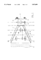
- FIG. 3 is an end view of FIG. 1;
- FIG. 4 is a cross-section through the line 4--4 of FIG. 1 showing the form that the paper takes up at that stage;
- FIG. 5 is a cross-section through the line 5--5 of FIG. 1 showing the form that the paper takes up at that stage;
- FIG. 6 is a cross-section through the line 6--6 of FIG. 1 showing the form that the paper takes up at that stage;
- FIG. 7 is a cross-section through the line 7--7 of FIG. 1 showing the form that the paper takes up at that stage;
- FIG. 8 is a close up view of the central part of the paper in FIG. 7;
- FIG. 9 is a plan view similar to FIG. 1 of an alternative dunnage forming machine
- FIG. 10 is a side view of FIG. 9, and FIG. 11 is an end view of FIG. 9.
- paper 10 is fed from a single multiply roll 12 of paper or, alternatively and not shown, from three separate paper rolls.
- the paper 10 passes between an upper flat tapering wall 14 and a lower flat inwardly tapering former 16.
- the sides of the former 16 are each defined by an arcuate wall 18 that extends through approximately 180°.
- the paper is pulled off the roll 12 by two pairs of spaced rear rubber nip rollers 20A and a forward pair of rubber nip rollers 20B.
- the lower nip rollers are driven and the upper idler nip rollers are urged, by the weight of the wall 14 or by springs (not shown) towards the lower rollers to trap the paper 10 between the pairs of rollers.
- the wall 14 and the former 16 have openings 22 to allow the upper nip rollers to contact the paper.
- the wall 14 starts near the rollers 20A to allow the free end of paper, on start up, to be fed directly into the rollers 20A. If desired, the rollers 20B can be omitted.
- the paper passes through a pair of meshing gear wheels 24.
- the gears are spring biased towards each other.
- the lower wheel is driven.
- the action of the gear wheels 24 deforms the surfaces of the paper that pass between them to hold the dunnage together loosely.
- the paper may be held in the position shown in FIGS. 7 and 8 as the gear wheels displace the cellulose fibres in adjacent layers to cause the fibres to interact. Alternatively or additionally the folds made in the paper by the gear wheels may be sufficient to connect the layers together.
- the driven rollers and the driven gear wheel are drivably connected by a belt or chain 26.
- the ratio between the driven roller and gear wheel is determined to feed paper at a slightly greater rate than the gear wheel could on its own. That ratio may be 1.07:1.0. This assists in the bunching up of the paper and therefore in increasing the bulk of the dunnage.
- a motor 38 shown schematically, drives the gear 24 and then the lower roller 20B by the belt 26.
- a pair of blades 33A and 33B are provided to cut the dunnage at the required length.
- the operation of these knives can be manual or automatic and is described later.
- the blades 33A and 33B are each arranged to cooperate with an anvil plate 34.
- Each blade is connected to an associated cog 35A and 35B and is able to partially rotate when a chain 36 is pulled to cause one of the blades 35A to pass against the anvil plate 34 cut over half of the width of the dunnage and subsequently one of the blades 35B to cut the remainder of the dunnage.
- the blades are encouraged to maintain a cutting action against the anvil by applying a small bending force at both ends of the anvil via jacking screws 37, as shown in FIG. 1. Furthermore as two blades extend from diametrically opposite parts of each cog the dunnage is able to be cut through upon a 180° rotation of the cogs, and the cutting life of the apparatus is more than doubled compared to the life with a single blade.
- FIGS. 9 to 11 The modified embodiment shown in FIGS. 9 to 11 will now be described.
- the machine shown in those figures corresponds largely with those shown in the previous FIGS. 1 to 8, including the cross sectional views 4, 5 and 6 and only the differences will be described.
- FIG. 9 the downstream rollers 20B have been omitted and only the upstream rollers 20A are present.
- the lower rollers 20A are gear wheels to increase the traction exerted upon the paper as it is being fed and the drive belt 26 passes around idler wheels 39, to power the lower rollers from the motor 38.
- the upper flat tapering wall 14 is inclined upwardly in the downstream direction, as shown in FIG. 10.
- the blades 33A and 33B are shortened slightly and they are in place so that they simultaneously make a cut and just fail to meet at their remote ends when making the cut.
Abstract
Description
Claims (13)
Applications Claiming Priority (3)
| Application Number | Priority Date | Filing Date | Title |
|---|---|---|---|
| GB9409973 | 1994-05-18 | ||
| GB9409973A GB9409973D0 (en) | 1994-05-18 | 1994-05-18 | Packaging material making machine |
| PCT/GB1995/001094 WO1995031296A2 (en) | 1994-05-18 | 1995-05-15 | Packaging material making machine |
Publications (1)
| Publication Number | Publication Date |
|---|---|
| US5873809A true US5873809A (en) | 1999-02-23 |
Family
ID=10755358
Family Applications (1)
| Application Number | Title | Priority Date | Filing Date |
|---|---|---|---|
| US08/737,230 Expired - Lifetime US5873809A (en) | 1994-05-18 | 1995-05-15 | Packaging material making machine |
Country Status (6)
| Country | Link |
|---|---|
| US (1) | US5873809A (en) |
| EP (1) | EP0759849B1 (en) |
| JP (1) | JPH10500074A (en) |
| DE (1) | DE69503128T2 (en) |
| GB (1) | GB9409973D0 (en) |
| WO (1) | WO1995031296A2 (en) |
Cited By (14)
| Publication number | Priority date | Publication date | Assignee | Title |
|---|---|---|---|---|
| US6120428A (en) * | 1995-06-07 | 2000-09-19 | Ranpak Corp. | Loading assembly for a cushioning conversion machine and method thereof |
| US20030176266A1 (en) * | 2002-03-12 | 2003-09-18 | John Walter | Geometric folding of a web used in a disposable absorbent article |
| US6632165B1 (en) | 2000-11-01 | 2003-10-14 | Guy Letourneau | Paper conversion dispenser machine |
| EP1645406A1 (en) * | 2005-02-17 | 2006-04-12 | Reinhard Keller | Machine for making paper cushioning products |
| US7083560B2 (en) * | 1999-09-09 | 2006-08-01 | Ranpak Corp. | Cushioning conversion machine having heavy duty characteristics |
| US20070021286A1 (en) * | 1999-09-03 | 2007-01-25 | Kobben Pierre H G | Cushioning conversion machine having heavy duty characteristics |
| US20070107918A1 (en) * | 2005-09-09 | 2007-05-17 | The Procter & Gamble Company | Folding system and process for a continuous moving web operation |
| US20070117703A1 (en) * | 2005-11-22 | 2007-05-24 | Sealed Air Corporation | Machine and method for converting a web of material into dunnage |
| US20080076653A1 (en) * | 2006-09-08 | 2008-03-27 | Shaw Kenneth L | Cushioning product, machine and method |
| US20100273624A1 (en) * | 2006-06-10 | 2010-10-28 | Ranpak Corp. | Compact dunnage converter |
| CN101970221A (en) * | 2007-09-24 | 2011-02-09 | 兰帕克公司 | Dunnage conversion machine and method |
| US8167783B2 (en) | 2006-04-11 | 2012-05-01 | Pack-Tiger Gmbh | Machine for the manufacture of paper padding |
| US20170066215A1 (en) * | 2014-05-01 | 2017-03-09 | Ranpak Corp. | Machine and method for producing dunnage having an x-shaped cross-sectional profile |
| US11207860B2 (en) | 2015-02-26 | 2021-12-28 | Ranpak Corp. | Dunnage conversion system and method for expanding pre-slit sheet stock material |
Families Citing this family (25)
| Publication number | Priority date | Publication date | Assignee | Title |
|---|---|---|---|---|
| US5823936A (en) * | 1996-02-08 | 1998-10-20 | Ranpak Corp. | Loading assembly and method for cushioning conversion machine |
| US6015374A (en) * | 1995-10-16 | 2000-01-18 | Ranpak Corp. | Compact cushioning conversion machine and method using pre-folded paper |
| US6168847B1 (en) | 1996-01-11 | 2001-01-02 | Ranpak Corporation | Pre-folded stock material for use in a cushioning conversion machine |
| FR2743748B1 (en) * | 1996-01-22 | 1998-03-27 | Naturembal Sa | DEVICE FOR MEASURING THE LENGTH OF PADDED BELTS |
| AU1448897A (en) * | 1996-01-22 | 1997-08-20 | Naturembal (Societe Anonyme) | Cushioning pad production machine with a system for measuring the length of the resulting pad |
| US5749824A (en) * | 1996-09-05 | 1998-05-12 | Ranpak Corp. | Conversion machine loader and method |
| US6155963A (en) * | 1997-07-28 | 2000-12-05 | Ranpak Corp. | Cushioning conversion machine with power infeed |
| US6210310B1 (en) | 1998-01-12 | 2001-04-03 | Ranpak Corp. | Cushioning conversion machine and method with enhanced stock separation and forming |
| EP1047545B1 (en) | 1998-01-12 | 2003-06-04 | Ranpak Corp. | Cushioning conversion machine and method |
| AU3995999A (en) * | 1998-05-15 | 1999-12-06 | Ranpak Corp. | Cushioning conversion machine and method |
| EP1348536A3 (en) * | 1998-05-15 | 2004-08-18 | Ranpak Corp. | Cushioning conversion machine and method |
| US6174273B1 (en) | 1998-12-18 | 2001-01-16 | Ranpak Corp. | Cushioning conversion machine with tension control |
| DE10030215A1 (en) * | 2000-06-20 | 2002-01-03 | Reichenecker Hans Storopack | Device for producing filling material |
| US6503182B2 (en) * | 2001-03-29 | 2003-01-07 | Zsolt Design Engineering, Inc. | Compact apparatus and system for creating and dispensing cushioning dunnage |
| GB2467399A (en) * | 2009-02-03 | 2010-08-04 | Easypack Ltd | Metal roll stopper. |
| CN107215006A (en) * | 2016-03-21 | 2017-09-29 | 陈泽生 | Paper material, devices, systems, and methods needed for paper washer manufacturing system |
| EP3241471B1 (en) | 2016-05-03 | 2019-07-03 | Papier-Mettler KG | Packaging paper dispenser device |
| DE202016002839U1 (en) | 2016-05-03 | 2016-06-20 | Papier-Mettler Kg | Verpackungspapierdispenservorrichtung |
| AT518269B1 (en) * | 2016-05-06 | 2017-09-15 | Gerhard Dallinger | Apparatus for producing a continuous paper packaging material |
| DE102021124380A1 (en) | 2021-09-21 | 2023-03-23 | Progress Packaging Gmbh | Device and method for producing filling material with a pressing device |
| DE102021125090A1 (en) | 2021-09-28 | 2023-03-30 | Sprick Gmbh Bielefelder Papier- Und Wellpappenwerke & Co. | Compact drive/motor unit |
| WO2023052439A2 (en) | 2021-09-28 | 2023-04-06 | Sprick Gmbh Bielefelder Papier- Und Wellpappenwerke & Co. | Discharge conveyor belt |
| DE102021125092A1 (en) | 2021-09-28 | 2023-03-30 | Sprick Gmbh Bielefelder Papier- Und Wellpappenwerke & Co. | Forming station with guide wall |
| DE102021125103A1 (en) | 2021-09-28 | 2023-03-30 | Sprick Gmbh Bielefelder Papier- Und Wellpappenwerke & Co. | Forming station with drive |
| WO2023052433A2 (en) * | 2021-09-28 | 2023-04-06 | Sprick Gmbh Bielefelder Papier- Und Wellpappenwerke & Co. | Forming station with guide wall |
Citations (26)
| Publication number | Priority date | Publication date | Assignee | Title |
|---|---|---|---|---|
| US2786399A (en) * | 1952-03-06 | 1957-03-26 | Veyne V Mason | Formation of crumpled sheet material filter elements and the like |
| US2924154A (en) * | 1956-08-27 | 1960-02-09 | Luber Finer Inc | Method and apparatus for crumpling paper |
| US3164069A (en) * | 1962-09-17 | 1965-01-05 | Ludlow Corp | Paper yarn and methods and apparatus for making same |
| US3347136A (en) * | 1963-02-21 | 1967-10-17 | Kure Gregers | Process and arrangement for production and placing of filling material in hollow building elements |
| US3425107A (en) * | 1965-10-11 | 1969-02-04 | Kanebo Ltd | Apparatus for developing crimps by heating composite filament |
| US3509797A (en) * | 1967-05-22 | 1970-05-05 | Arpax Co | Mechanism for producing cushioning dunnage |
| US3509798A (en) * | 1968-02-07 | 1970-05-05 | Arpax Co | Mechanism and method for producing cushioning dunnage |
| US3603216A (en) * | 1970-02-09 | 1971-09-07 | Arpax Co | Method for producing cushioning dunnage |
| US3613522A (en) * | 1969-09-12 | 1971-10-19 | Arpax Co | Method of producing cushioning dunnage |
| US3655500A (en) * | 1968-02-07 | 1972-04-11 | Arpax Co | A resilient cushioning dunnage product for use in packaging and packing |
| US3717074A (en) * | 1967-12-04 | 1973-02-20 | Hoerner Waldorf Corp | Deadened crease |
| US3799039A (en) * | 1971-12-14 | 1974-03-26 | Ranpak Corp | Cushioning dunnage mechanism and method |
| US4026198A (en) * | 1975-05-01 | 1977-05-31 | Ranpak Corporation | Cushioning dunnage mechanism, transfer cart therefor, and method |
| US4237776A (en) * | 1978-06-02 | 1980-12-09 | Ranpak Corporation | Cushioning dunnage mechanism |
| US4410315A (en) * | 1980-10-03 | 1983-10-18 | Beloit Corporation | Low velocity trim removal means and method |
| US4421501A (en) * | 1982-01-18 | 1983-12-20 | Scheffer Bruce A | Web folding apparatus |
| US4699609A (en) * | 1986-02-25 | 1987-10-13 | Ranpak Corp. | Electric cutter mechanism for dunnage converter |
| US4717613A (en) * | 1984-05-10 | 1988-01-05 | Ranpak Corporation | Mechanism and method for producing cushioning dunnage |
| US4750896A (en) * | 1985-10-28 | 1988-06-14 | Ranpak Corp. | Method and mechanism for producing cushioning dunnage product |
| EP0427834A1 (en) * | 1989-05-03 | 1991-05-22 | Ranpak Corp | Stitching gear assembly having perforating projections thereon, for use in converter adapted to produce pad-like cushioning material, and method. |
| WO1992005948A1 (en) * | 1990-10-05 | 1992-04-16 | Ranpak Corporation | Downsized cushioning dunnage conversion machine and packaging systems employing the same |
| US5173352A (en) * | 1989-11-02 | 1992-12-22 | Ranpak Corporation | Resilient packing product and method and apparatus for making the same |
| EP0523382A2 (en) * | 1991-06-17 | 1993-01-20 | Sealed Air Corporation | Apparatus for fabricating dunnage material from continuous web material |
| US5188581A (en) * | 1988-01-04 | 1993-02-23 | Ranpak Corp. | Method for producing a narrow width cushioning paper product |
| WO1993008980A1 (en) * | 1991-11-01 | 1993-05-13 | Ranpak Corporation | Edge-tension controlling device for a cushioning conversion machine |
| WO1993019931A1 (en) * | 1992-03-31 | 1993-10-14 | Ranpak Corp. | Method and apparatus for making an improved resilient packing product |
-
1994
- 1994-05-18 GB GB9409973A patent/GB9409973D0/en active Pending
-
1995
- 1995-05-15 JP JP7529455A patent/JPH10500074A/en not_active Ceased
- 1995-05-15 DE DE69503128T patent/DE69503128T2/en not_active Expired - Lifetime
- 1995-05-15 EP EP95918679A patent/EP0759849B1/en not_active Expired - Lifetime
- 1995-05-15 WO PCT/GB1995/001094 patent/WO1995031296A2/en active IP Right Grant
- 1995-05-15 US US08/737,230 patent/US5873809A/en not_active Expired - Lifetime
Patent Citations (30)
| Publication number | Priority date | Publication date | Assignee | Title |
|---|---|---|---|---|
| US2786399A (en) * | 1952-03-06 | 1957-03-26 | Veyne V Mason | Formation of crumpled sheet material filter elements and the like |
| US2924154A (en) * | 1956-08-27 | 1960-02-09 | Luber Finer Inc | Method and apparatus for crumpling paper |
| US3164069A (en) * | 1962-09-17 | 1965-01-05 | Ludlow Corp | Paper yarn and methods and apparatus for making same |
| US3347136A (en) * | 1963-02-21 | 1967-10-17 | Kure Gregers | Process and arrangement for production and placing of filling material in hollow building elements |
| US3425107A (en) * | 1965-10-11 | 1969-02-04 | Kanebo Ltd | Apparatus for developing crimps by heating composite filament |
| US3509797A (en) * | 1967-05-22 | 1970-05-05 | Arpax Co | Mechanism for producing cushioning dunnage |
| US3717074A (en) * | 1967-12-04 | 1973-02-20 | Hoerner Waldorf Corp | Deadened crease |
| US3509798A (en) * | 1968-02-07 | 1970-05-05 | Arpax Co | Mechanism and method for producing cushioning dunnage |
| US3655500A (en) * | 1968-02-07 | 1972-04-11 | Arpax Co | A resilient cushioning dunnage product for use in packaging and packing |
| US3613522A (en) * | 1969-09-12 | 1971-10-19 | Arpax Co | Method of producing cushioning dunnage |
| US3603216A (en) * | 1970-02-09 | 1971-09-07 | Arpax Co | Method for producing cushioning dunnage |
| US3799039A (en) * | 1971-12-14 | 1974-03-26 | Ranpak Corp | Cushioning dunnage mechanism and method |
| US4109040A (en) * | 1975-05-01 | 1978-08-22 | Ranpak Corporation | Cushioning dunnage product produced from cushioning dunnage mechanism |
| US4085662A (en) * | 1975-05-01 | 1978-04-25 | Ranpak Corporation | Method of making and using cushioning dunnage material |
| US4026198A (en) * | 1975-05-01 | 1977-05-31 | Ranpak Corporation | Cushioning dunnage mechanism, transfer cart therefor, and method |
| US4237776A (en) * | 1978-06-02 | 1980-12-09 | Ranpak Corporation | Cushioning dunnage mechanism |
| US4410315A (en) * | 1980-10-03 | 1983-10-18 | Beloit Corporation | Low velocity trim removal means and method |
| US4421501A (en) * | 1982-01-18 | 1983-12-20 | Scheffer Bruce A | Web folding apparatus |
| US4717613A (en) * | 1984-05-10 | 1988-01-05 | Ranpak Corporation | Mechanism and method for producing cushioning dunnage |
| US4750896A (en) * | 1985-10-28 | 1988-06-14 | Ranpak Corp. | Method and mechanism for producing cushioning dunnage product |
| US4699609A (en) * | 1986-02-25 | 1987-10-13 | Ranpak Corp. | Electric cutter mechanism for dunnage converter |
| US5188581A (en) * | 1988-01-04 | 1993-02-23 | Ranpak Corp. | Method for producing a narrow width cushioning paper product |
| EP0427834A1 (en) * | 1989-05-03 | 1991-05-22 | Ranpak Corp | Stitching gear assembly having perforating projections thereon, for use in converter adapted to produce pad-like cushioning material, and method. |
| US5173352A (en) * | 1989-11-02 | 1992-12-22 | Ranpak Corporation | Resilient packing product and method and apparatus for making the same |
| US5173352B1 (en) * | 1989-11-02 | 1998-02-17 | Ranpak Corp | Resilient packing product and method and apparatus for making the same |
| WO1992005948A1 (en) * | 1990-10-05 | 1992-04-16 | Ranpak Corporation | Downsized cushioning dunnage conversion machine and packaging systems employing the same |
| EP0523382A2 (en) * | 1991-06-17 | 1993-01-20 | Sealed Air Corporation | Apparatus for fabricating dunnage material from continuous web material |
| US5203761A (en) * | 1991-06-17 | 1993-04-20 | Sealed Air Corporation | Apparatus for fabricating dunnage material from continuous web material |
| WO1993008980A1 (en) * | 1991-11-01 | 1993-05-13 | Ranpak Corporation | Edge-tension controlling device for a cushioning conversion machine |
| WO1993019931A1 (en) * | 1992-03-31 | 1993-10-14 | Ranpak Corp. | Method and apparatus for making an improved resilient packing product |
Cited By (24)
| Publication number | Priority date | Publication date | Assignee | Title |
|---|---|---|---|---|
| US6120428A (en) * | 1995-06-07 | 2000-09-19 | Ranpak Corp. | Loading assembly for a cushioning conversion machine and method thereof |
| US20070021286A1 (en) * | 1999-09-03 | 2007-01-25 | Kobben Pierre H G | Cushioning conversion machine having heavy duty characteristics |
| US7083560B2 (en) * | 1999-09-09 | 2006-08-01 | Ranpak Corp. | Cushioning conversion machine having heavy duty characteristics |
| US6632165B1 (en) | 2000-11-01 | 2003-10-14 | Guy Letourneau | Paper conversion dispenser machine |
| US20030176266A1 (en) * | 2002-03-12 | 2003-09-18 | John Walter | Geometric folding of a web used in a disposable absorbent article |
| US6699166B2 (en) * | 2002-03-12 | 2004-03-02 | Paragon Trade Brands, Inc. | Geometric folding of a web used in a disposable absorbent article |
| EP1645406A1 (en) * | 2005-02-17 | 2006-04-12 | Reinhard Keller | Machine for making paper cushioning products |
| US20070107918A1 (en) * | 2005-09-09 | 2007-05-17 | The Procter & Gamble Company | Folding system and process for a continuous moving web operation |
| US7500941B2 (en) * | 2005-09-09 | 2009-03-10 | The Procter & Gamble Company | Folding system and process for a continuous moving web operation |
| US20070117703A1 (en) * | 2005-11-22 | 2007-05-24 | Sealed Air Corporation | Machine and method for converting a web of material into dunnage |
| US8167783B2 (en) | 2006-04-11 | 2012-05-01 | Pack-Tiger Gmbh | Machine for the manufacture of paper padding |
| US10239276B2 (en) | 2006-06-10 | 2019-03-26 | Ranpak Corp. | Compact dunnage converter |
| US20100273624A1 (en) * | 2006-06-10 | 2010-10-28 | Ranpak Corp. | Compact dunnage converter |
| US8419606B2 (en) * | 2006-06-10 | 2013-04-16 | Ranpak Corp. | Compact dunnage converter |
| US11472150B2 (en) | 2006-06-10 | 2022-10-18 | Ranpak Corp. | Compact dunnage converter |
| US20080076653A1 (en) * | 2006-09-08 | 2008-03-27 | Shaw Kenneth L | Cushioning product, machine and method |
| CN101970221A (en) * | 2007-09-24 | 2011-02-09 | 兰帕克公司 | Dunnage conversion machine and method |
| CN101970221B (en) * | 2007-09-24 | 2015-01-14 | 兰帕克公司 | Dunnage conversion machine and method |
| US9669596B2 (en) | 2007-09-24 | 2017-06-06 | Ranpak Corp. | Dunnage conversion machine and method |
| US11325340B2 (en) | 2007-09-24 | 2022-05-10 | Ranpak Corp. | Dunnage conversion machine and method |
| US20170066215A1 (en) * | 2014-05-01 | 2017-03-09 | Ranpak Corp. | Machine and method for producing dunnage having an x-shaped cross-sectional profile |
| US11123943B2 (en) * | 2014-05-01 | 2021-09-21 | Ranpak Corp. | Machine and method for producing dunnage having an x-shaped cross-sectional profile |
| US11207860B2 (en) | 2015-02-26 | 2021-12-28 | Ranpak Corp. | Dunnage conversion system and method for expanding pre-slit sheet stock material |
| US11787145B2 (en) | 2015-02-26 | 2023-10-17 | Ranpak Corp. | Dunnage conversion system and method for expanding pre-slit sheet stock material |
Also Published As
| Publication number | Publication date |
|---|---|
| WO1995031296A2 (en) | 1995-11-23 |
| DE69503128T2 (en) | 1998-12-24 |
| JPH10500074A (en) | 1998-01-06 |
| GB9409973D0 (en) | 1994-07-06 |
| DE69503128D1 (en) | 1998-07-30 |
| EP0759849B1 (en) | 1998-06-24 |
| EP0759849A1 (en) | 1997-03-05 |
| WO1995031296A3 (en) | 1996-01-04 |
Similar Documents
| Publication | Publication Date | Title |
|---|---|---|
| US5873809A (en) | Packaging material making machine | |
| US4750896A (en) | Method and mechanism for producing cushioning dunnage product | |
| KR100202226B1 (en) | Rewinding machine and method for the formation of logs of web material with means for severing the web material | |
| AU703893B2 (en) | Improvements to machines and methods for manufacturing packing materials by crumpling paper | |
| CA1072795A (en) | Cushioning dunnage mechanism, transfer cart therefor, and method | |
| US4839210A (en) | Method and mechanism for producing cushioning dunnage product | |
| NO178019B (en) | Gear-like stitching unit for use in a converter mechanism, usable for making pillow-like dunnage material, and method for making pillow-shaped dunnage product | |
| DE2715230C2 (en) | Device for packing articles in a double tube | |
| CN109715380B (en) | Dunnage conversion machine and method | |
| US3984272A (en) | Method and apparatus for successively forming disposable diapers | |
| US5076555A (en) | Apparatus for partially severing strip of paper along lines offset from lines of weakening in the paper | |
| US2541387A (en) | Method of and machine for packaging flexible sheets | |
| JPS6186351A (en) | Raw fabric reel changeover method for packaging machine and device thereof | |
| EP0137334A2 (en) | Device for making packages, especially cigarette cartons | |
| US3838632A (en) | Method and apparatus for making corrugated containers of longitudinally corrugated strips on continuous basis | |
| US20020000400A1 (en) | Device for removal of trimmings in the production of rolls of web material | |
| JPH052568B2 (en) | ||
| JPS62168832A (en) | Selecting and feeding device for band-shaped material | |
| US3967544A (en) | Grocery sack process and machine | |
| AU660791B2 (en) | Apparatus for rolling up a printed product and winding a wrapping around the roll | |
| JPH05154266A (en) | Device for cutting off section from web of material having perforation formed in lateral direction | |
| US3202064A (en) | Machine for applying cord handles to paper bags | |
| FI81553B (en) | MASKIN FOER FORMNING AV EN RAD OMSLAGSPAKET BESTAOENDE AV LAMELLERADE PAPPERSBLAD. | |
| EP0681978A2 (en) | Method and unit for producing tear strips | |
| CN220045526U (en) | Shoe cover machine |
Legal Events
| Date | Code | Title | Description |
|---|---|---|---|
| AS | Assignment |
Owner name: EASYPACK LIMITED, UNITED KINGDOM Free format text: ASSIGNMENT OF ASSIGNORS INTEREST;ASSIGNORS:KEMPSTER, MARK ALAN;PANTHER, TIMOTHY EDWARD LAWRENCE;REEL/FRAME:008485/0077 Effective date: 19961017 |
|
| STCF | Information on status: patent grant |
Free format text: PATENTED CASE |
|
| FPAY | Fee payment |
Year of fee payment: 4 |
|
| FPAY | Fee payment |
Year of fee payment: 8 |
|
| FPAY | Fee payment |
Year of fee payment: 12 |
|
| AS | Assignment |
Owner name: PREGIS LIMITED, UNITED KINGDOM Free format text: CHANGE OF NAME;ASSIGNOR:EASYPACK LIMITED;REEL/FRAME:048737/0592 Effective date: 20171221 |