US5890558A - All-wheel steering mechanism for a cleaning vehicle - Google Patents
All-wheel steering mechanism for a cleaning vehicle Download PDFInfo
- Publication number
- US5890558A US5890558A US08/827,392 US82739297A US5890558A US 5890558 A US5890558 A US 5890558A US 82739297 A US82739297 A US 82739297A US 5890558 A US5890558 A US 5890558A
- Authority
- US
- United States
- Prior art keywords
- wheel
- pivot
- vehicle
- pivot arm
- steering
- Prior art date
- Legal status (The legal status is an assumption and is not a legal conclusion. Google has not performed a legal analysis and makes no representation as to the accuracy of the status listed.)
- Expired - Fee Related
Links
- 238000004140 cleaning Methods 0.000 title claims abstract description 63
- 238000005201 scrubbing Methods 0.000 claims description 11
- 230000007935 neutral effect Effects 0.000 description 7
- 239000012530 fluid Substances 0.000 description 6
- 238000010408 sweeping Methods 0.000 description 5
- 241001417527 Pempheridae Species 0.000 description 3
- 241000380131 Ammophila arenaria Species 0.000 description 1
- 239000010426 asphalt Substances 0.000 description 1
- 239000011449 brick Substances 0.000 description 1
- 239000000463 material Substances 0.000 description 1
- 230000001141 propulsive effect Effects 0.000 description 1
Images


Classifications
-
- A—HUMAN NECESSITIES
- A47—FURNITURE; DOMESTIC ARTICLES OR APPLIANCES; COFFEE MILLS; SPICE MILLS; SUCTION CLEANERS IN GENERAL
- A47L—DOMESTIC WASHING OR CLEANING; SUCTION CLEANERS IN GENERAL
- A47L11/00—Machines for cleaning floors, carpets, furniture, walls, or wall coverings
- A47L11/40—Parts or details of machines not provided for in groups A47L11/02 - A47L11/38, or not restricted to one of these groups, e.g. handles, arrangements of switches, skirts, buffers, levers
- A47L11/4061—Steering means; Means for avoiding obstacles; Details related to the place where the driver is accommodated
-
- B—PERFORMING OPERATIONS; TRANSPORTING
- B62—LAND VEHICLES FOR TRAVELLING OTHERWISE THAN ON RAILS
- B62D—MOTOR VEHICLES; TRAILERS
- B62D61/00—Motor vehicles or trailers, characterised by the arrangement or number of wheels, not otherwise provided for, e.g. four wheels in diamond pattern
- B62D61/06—Motor vehicles or trailers, characterised by the arrangement or number of wheels, not otherwise provided for, e.g. four wheels in diamond pattern with only three wheels
- B62D61/08—Motor vehicles or trailers, characterised by the arrangement or number of wheels, not otherwise provided for, e.g. four wheels in diamond pattern with only three wheels with single front wheel
-
- B—PERFORMING OPERATIONS; TRANSPORTING
- B62—LAND VEHICLES FOR TRAVELLING OTHERWISE THAN ON RAILS
- B62D—MOTOR VEHICLES; TRAILERS
- B62D7/00—Steering linkage; Stub axles or their mountings
- B62D7/06—Steering linkage; Stub axles or their mountings for individually-pivoted wheels, e.g. on king-pins
- B62D7/14—Steering linkage; Stub axles or their mountings for individually-pivoted wheels, e.g. on king-pins the pivotal axes being situated in more than one plane transverse to the longitudinal centre line of the vehicle, e.g. all-wheel steering
- B62D7/142—Steering linkage; Stub axles or their mountings for individually-pivoted wheels, e.g. on king-pins the pivotal axes being situated in more than one plane transverse to the longitudinal centre line of the vehicle, e.g. all-wheel steering specially adapted for particular vehicles, e.g. tractors, carts, earth-moving vehicles, trucks
-
- E—FIXED CONSTRUCTIONS
- E01—CONSTRUCTION OF ROADS, RAILWAYS, OR BRIDGES
- E01H—STREET CLEANING; CLEANING OF PERMANENT WAYS; CLEANING BEACHES; DISPERSING OR PREVENTING FOG IN GENERAL CLEANING STREET OR RAILWAY FURNITURE OR TUNNEL WALLS
- E01H1/00—Removing undesirable matter from roads or like surfaces, with or without moistening of the surface
Definitions
- the present invention relates to cleaning vehicles and in particular to a steering mechanism for a cleaning vehicle which conjointly turns or pivots all of the wheels of the cleaning vehicle when a change in vehicle direction is desired.
- a typical three-wheel cleaning vehicle is configured such that the third wheel, which is longitudinally offset from the other two wheels of the vehicle, is located at the front of the vehicle and is selectively pivotal, while the other two wheels are non-pivotal, such that the cleaning vehicle steers from the front.
- the third wheel can alternatively be located behind the other two wheels at the rear of the vehicle and consequently the vehicle will steer from the rear.
- the vehicle With just one wheel being pivotal to steer the vehicle, the vehicle is limited in maneuverability when it is positioned close to objects, such as when sweeping and scrubbing along a wall.
- the vehicle When a rear-steering vehicle is being used to clean along the edge of a wall, the vehicle must be inched away from the wall well in advance of encountering the upcoming obstruction in order to steer the vehicle away from the wall when the obstruction is encountered. Otherwise, in a rear-steering vehicle, a sharp turn will shift the back end of the vehicle up against the wall creating interference and possibly damaging the vehicle and the wall.
- the third wheel that steers the vehicle When the third wheel that steers the vehicle is located at the front of the vehicle, such as on a typical direct-throw style sweeper, the wheel is placed directly in the path of the debris and limits the effectiveness of this type of sweeper. Often, to maximize maneuverability on a three-wheeled vehicle, the third wheel is also the drive wheel as well as the steering wheel. Thus, the power that propels the vehicle is transferred through just one wheel to the support surface. When just one drive wheel is used, having sufficient traction between the drive wheel and the support surface is a concern and a problem, especially in connection with scrubbing machines where the drive wheel encounters wet surfaces created by the cleaning vehicle.
- the present all-wheel steering mechanism powers two front wheels for improved traction over a one-wheel powered design.
- the steering mechanism connects the two front wheels and a third rear wheel such that each wheel conjointly turns or pivots when a change in direction of the vehicle is desired.
- the cleaning vehicle of the present invention with the all-wheel steering mechanism is scrubbing or sweeping close to a wall and makes a turn
- the vehicle may be pulled away from the wall by conjointly turning both front wheels in a first direction, such that the front end of the vehicle moves away from the wall, and conjointly turning the rear wheel in a second opposite direction, such that the back end of the vehicle moves toward the wall. This provides a quick break-away from the wall or other obstruction without creating any interference.
- the third wheel is located at the rear of the vehicle behind the two front drive wheels. Therefore the sweeping mechanism of the cleaning vehicle, which is a direct-throw style, has no wheels in the debris path causing interference. As the two front drive wheels are powered and are located ahead of the scrubbing system, they will typically be located on a dry surface to provide enhanced traction and driving control.
- a ride-on cleaning vehicle having an all-wheel steering mechanism for movement over a support surface that is to be cleaned.
- the cleaning vehicle includes a first wheel mounted to the vehicle for rotation about a first rotational axis and for pivotal movement or turning about a first pivot axis, a second wheel mounted to the vehicle for rotation about a second rotational axis and for pivotal movement or turning about a second pivot axis, and a third wheel mounted to the vehicle for rotation about a third rotational axis and for pivotal movement or turning about a third pivot axis.
- the first and second wheels are located generally transversely across from one another and toward the front of the vehicle.
- the third wheel is located longitudinally behind the first and second wheels toward the rear end of the vehicle, such that the three wheels are located in a generally triangular arrangement relative to one another.
- the cleaning vehicle includes an all-wheel steering mechanism for selectively and conjointly pivoting the first, second and third wheels respectively about their first, second and third pivot axes.
- the steering mechanism includes a pivot arm pivotally attached to the frame of the vehicle such that the pivot arm is pivotal about a fourth pivot axis.
- a first steering linkage operatively connects the pivot arm to the first wheel.
- a second steering linkage operatively connects the pivot arm to the second wheel.
- a third steering linkage operatively connects the pivot arm to the third wheel. Pivotal movement of the pivot arm about the fourth pivot axis causes the steering linkages to conjointly pivot or turn the first, second and third wheels respectively about the first, second and third pivot axes.
- Pivotal movement of the pivot arm through a selected angular magnitude results in pivoting the first wheel a first angular magnitude, pivoting the second wheel a second angular magnitude, and pivoting the third wheel a third angular magnitude, wherein the second angular magnitude is greater than the first angular magnitude and the third angular magnitude is greater than the second angular magnitude.
- the cleaning vehicle includes actuating means for selectively pivoting the pivot arm about the fourth pivot axis.
- the actuating means includes a hydraulic cylinder having a selectively extendable and retractable ram connected to the pivot arm.
- the actuating means also includes a manually operated pump for selectively extending and retracting the ram of the cylinder.
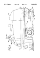
- FIG. 1 is a side elevational view of the cleaning vehicle having the all-wheel steering mechanism of the present invention.
- FIG. 2 is a cross sectional view taken along lines 2--2 of FIG. 1 showing the steering mechanism and wheels positioned for linear travel.
- FIG. 3 is a top plan view of the steering mechanism and wheels positioned for making a left-hand turn.
- FIG. 4 is a top plan view of the steering mechanism and wheels positioned for making a right-hand turn.
- FIG. 1 shows the cleaning vehicle 10 of the present invention.
- the cleaning vehicle 10 is self-propelled for movement over a support surface 12 that is to be cleaned by sweeping and/or scrubbing.
- the support surface 12 may comprise a floor, sidewalk, parking lot and other types of surfaces that may be formed from concrete, asphalt, tile, brick and other materials.
- the cleaning vehicle 10 includes a front end 14, a rear end 16 and a frame 17.
- the cleaning vehicle 10 also includes a scrub brush 18 mounted at the front end 14 for rotation about a vertical axis and a scrubbing mechanism 20 mounted at the rear end 16.
- the scrubbing mechanism 20 includes one or more scrub brushes (not shown), a dispenser for dispensing cleaning fluid onto the surface 12 to be cleaned and a squeegee 22 for picking up the cleaning fluid from the surface 12 along with any dirt or debris that has been dislodged by the scrub brushes.
- the scrub brush 18 and the scrubbing mechanism 20 may be selectively raised to disengage the support surface 12 or lowered to engage the support surface 12 as desired.
- the cleaning vehicle 10 includes an all-wheel steering mechanism 30.
- the steering mechanism 30 includes a pivot arm 32 that is pivotally attached to the frame 17 for selective pivotal movement about a vertical pivot axis 34.
- the steering mechanism 30 also includes a first steering linkage 36.
- the first steering linkage 36 includes a wheel support 38 pivotally mounted to the frame 17 of the cleaning vehicle 10 for selective pivotal movement about a vertical pivot axis 40.
- a steering lever arm 42 includes a first end 44 that is rigidly affixed to the wheel support 38 for conjoint pivotal movement therewith and a second end 46.
- a push rod 48 includes a first end 50 pivotally attached to the second end 46 of the steering lever arm 42 and a second end 52 pivotally attached to the pivot arm 32 for pivotal movement about a vertical pivot axis 54.
- the steering mechanism 30 includes a second steering linkage 60.
- the second steering linkage 60 includes a wheel support 62 pivotally attached to the frame 17 of the cleaning vehicle 10 for selective pivotal movement about a vertical pivot axis 64.
- the second steering linkage 60 also includes a steering lever arm 66 having a first end 68 rigidly affixed to the wheel support 62 for conjoint pivotal movement therewith and a second end 70.
- a push rod 72 includes a first end 74 pivotally attached to the second end 70 of the steering lever arm 66 and a second end 76 pivotally attached to the pivot arm 32 for selective pivotal movement about a vertical pivot axis 78.
- the steering mechanism 30 includes a third steering linkage 82.
- the third steering linkage 82 includes a wheel support 84 mounted to the frame 17 of the cleaning vehicle 10 for selective pivotal movement about a vertical pivot axis 86.
- the third steering linkage 82 includes a push rod 88 having a first end 90 pivotally attached to the wheel support 84 and a second end 92 pivotally attached to the pivot arm 32 for selective pivotal movement about a vertical pivot axis 94.
- the pivot axes 40, 64 and 86 are located in a generally triangular arrangement relative to one another.
- the cleaning vehicle 10 includes a first wheel 100, a second wheel 102 and a third wheel 104, each of which is rotatably mounted to the cleaning vehicle 10.
- the first wheel 100 is connected to the wheel support 38 of the first steering linkage 36 such that the wheel 100 is rotatable with respect thereto about a first horizontal rotational axis 106 and such that the wheel 100 is pivotal about the vertical pivot axis 40 conjointly with the wheel support 38.
- the second wheel 102 is rotatably connected to the wheel support 62 of the second steering linkage 60 such that the wheel 102 is rotatable with respect thereto about a second horizontal rotational axis 108 and such that the wheel 102 is pivotal about the vertical pivot axis 64 conjointly with the wheel support 62.
- the third wheel 104 is rotatably connected to the wheel support 84 of the third steering linkage 82 such that the third wheel 104 is rotatable with respect thereto about a third horizontal rotational axis 110 and such that the third wheel 104 is pivotal about the pivot axis 86 conjointly with the wheel support 84.
- the first and second wheels 100 and 102 are disposed transversely across from one another and are located on respective left and right sides of the cleaning vehicle 10 towards the front end 14 of the cleaning vehicle 10.
- the third wheel 104 is located longitudinally to the rear of the first and second wheels 100 and 102 and is located towards the rear end 16 of the cleaning vehicle 10.
- the wheels 100, 102 and 104 are located in a generally triangular arrangement with respect to one another.
- the steering mechanism 30 also includes an actuator mechanism 120.
- the actuator mechanism 120 includes a hydraulic cylinder 122 attached to the frame 17 of the cleaning vehicle 10.
- the hydraulic cylinder 122 includes a ram 124 having an end that is pivotally attached to the pivot arm 32 for selective pivotal movement about a vertical pivot axis 126.
- the ram 124 is selectively extendable and retractable within the hydraulic cylinder 122.
- a first hydraulic line 128 is attached to one end of the hydraulic cylinder 122 and a second hydraulic line 130 is attached to a second opposite end of the hydraulic cylinder 122.
- the opposite ends of the hydraulic lines 128 and 130 are respectively attached to a manually operable hydraulic pump 132, typically referred to as a helm unit.
- One type of pump 132 that is acceptable is manufactured by Teleflex under Model No. HH5231,SS1.4HELM.
- a wheel 134 is operably connected to the pump 132 to provide manual operation of the pump 132 by the driver or operator of the cleaning vehicle 10.
- Rotation of the wheel 134 by the operator of the cleaning vehicle 10 in a clockwise direction causes the pump 132 to pump hydraulic fluid through the first hydraulic line 128 into the hydraulic cylinder 122 thereby extending the ram 124 from the hydraulic cylinder 122.
- hydraulic fluid leaves the hydraulic cylinder 122 through the second hydraulic line 130 and flows to the pump 132.
- the pump 132 pumps hydraulic fluid through the second hydraulic line 130 into the hydraulic cylinder 122 thereby retracting the ram 124.
- hydraulic fluid flows from the hydraulic cylinder 122 through the first hydraulic line 128 to the pump 132.
- the cleaning vehicle 10 includes one or more batteries (not shown) electrically connected to an electric motor (not shown) for providing propulsive power to the cleaning vehicle 10.
- the motor is connected to a differential gear box 142.
- One type of gear box that is acceptable is manufactured by Comex under Model No. 5P276D.
- the gear box 142 is operatively connected to the first wheel 100 by a drive shaft 144 and a constant velocity joint 146 to provide rotational movement of the wheel 100 about the first rotational axis 106.
- the gear box 142 is also operatively connected to the second wheel 102 by a drive shaft 148 and a constant velocity joint 150 to provide rotational movement of the second wheel 102 about the second rotational axis 108.
- the drive means 142 thereby provides rotation of the wheels 100 and 102 about their respective rotational axes 106 and 108.
- the wheels 100 and 102 are drive and steering wheels, while the third wheel 104 is solely a steering wheel.
- the steering mechanism 30 positions the wheels 100, 102 and 104 such that the rotational axes 106, 108 and 110 thereof are parallel to one another whereby the wheels provide linear movement of the cleaning vehicle 10 over the support surface 12.
- the operator rotates the wheel 134 in a counter-clockwise direction such that the pump 132 retracts the ram 124 of the hydraulic cylinder 122 from the first neutral position shown in FIG. 2 to a second retracted position such as shown in FIG. 3.
- the ram 124 retracts into the cylinder 122
- the ram 124 pivots the pivot arm 32 about the pivot axis 34 in a counter-clockwise direction from its neutral position through a selected angular magnitude.
- the counter-clockwise pivotal movement of the pivot arm 32 causes the first steering linkage 36 to turn or pivot the first wheel 100 in a counter-clockwise direction about the pivot axis 40 through a first angular magnitude.
- the selected pivotal movement of the pivot arm 32 conjointly causes the second steering linkage 60 to turn or pivot the second wheel 102 in a counter-clockwise direction about the pivot axis 64 through a second angular magnitude that is smaller than the first angular magnitude through which the first wheel 100 was pivoted.
- the selected pivotal movement of the pivot arm 32 causes the third steering linkage 82 to turn or pivot the third wheel 104 in a clockwise direction about the pivot axis 86 through a third angular magnitude which is greater than the first and second angular magnitudes through which the first and second wheels 100 and 102 were pivoted.
- the selected pivotal movement of the pivot arm 32 provides three different rates of pivotal movement respectively to the wheels 100, 102 and 104.
- the relative lengths of the push rods 48, 72 and 88 and of the steering lever arms 42 and 66 may be adjusted to provide for various rates of wheel pivot for a selected magnitude of angular movement of the pivot arm 32.
- the steering mechanism 30 provides pivotal movement of the wheels 100, 102 and 104 such that when the wheels 100, 102 and 104 are pivoted from their neutral positions for linear travel as shown in FIG. 2, the rotational axes 106, 108 and 110 of the wheels approximately intersect at a common point 154.
- Each wheel 100, 102 and 104 will thereby rotate and travel along an arc of a respective circle wherein each circle has its center at the intersection point 154.
- This wheel arrangement minmizes the amount of dragging of any of the three wheels on the surface 12 during a turn, which minimizes the risk of leaving any tire marks on the surface 12.
- the operator of the cleaning vehicle 10 turns the wheel 134 in a clockwise direction thereby causing the pump 132 to extend the ram 124 of the hydraulic cylinder 122 from the neutral position as shown in FIG. 2 to an extended position such as shown in FIG. 4.
- the extension of the ram 124 from the neutral position to the extended position shown in FIG. 4 causes the pivot arm 32 to pivot in a clockwise direction about the pivot axis 34 from its first neutral position through a selected angular magnitude to a second position.
- the selected clockwise pivotal movement of the pivot arm 32 causes the first steering linkage 36 to turn or pivot the first wheel 100 in a clockwise direction about the pivot axis 40 through a first angular magnitude.
- the selected clockwise pivotal movement of the pivot arm 32 conjointly causes the second steering linkage 60 to cause the second wheel 102 to turn or pivot in a clockwise direction about the pivot axis 64 through a second angular magnitude which is larger than the first angular magnitude through which the first wheel 100 was pivoted.
- the selected clockwise pivotal movement of the pivot arm 32 conjointly causes the third steering linkage 82 to turn or pivot the third wheel 104 in a counter-clockwise direction about the pivot axis 86 through a third angular magnitude which is greater than both the first and second angular magnitudes through which first and second wheels 100 and 102 were pivoted.
- the wheels 100, 102 and 104 are pivoted as shown in FIG. 4 their respective rotational axes 106, 108 and 110 substantially intersect at a common intersection point.
Abstract
Description
Claims (19)
Priority Applications (1)
| Application Number | Priority Date | Filing Date | Title |
|---|---|---|---|
| US08/827,392 US5890558A (en) | 1997-03-27 | 1997-03-27 | All-wheel steering mechanism for a cleaning vehicle |
Applications Claiming Priority (1)
| Application Number | Priority Date | Filing Date | Title |
|---|---|---|---|
| US08/827,392 US5890558A (en) | 1997-03-27 | 1997-03-27 | All-wheel steering mechanism for a cleaning vehicle |
Publications (1)
| Publication Number | Publication Date |
|---|---|
| US5890558A true US5890558A (en) | 1999-04-06 |
Family
ID=25249101
Family Applications (1)
| Application Number | Title | Priority Date | Filing Date |
|---|---|---|---|
| US08/827,392 Expired - Fee Related US5890558A (en) | 1997-03-27 | 1997-03-27 | All-wheel steering mechanism for a cleaning vehicle |
Country Status (1)
| Country | Link |
|---|---|
| US (1) | US5890558A (en) |
Cited By (33)
| Publication number | Priority date | Publication date | Assignee | Title |
|---|---|---|---|---|
| US6116645A (en) * | 1997-04-22 | 2000-09-12 | New Holland North America, Inc. | Steering assembly for a work vehicle |
| US6212731B1 (en) * | 1998-04-24 | 2001-04-10 | Diversey Lever, Inc. | Apparatus for cleaning floors |
| US20030221890A1 (en) * | 2002-02-22 | 2003-12-04 | Berthold Fecteau | Three-wheeled vehicle with a continuously variable transmission |
| US20030221891A1 (en) * | 2002-02-22 | 2003-12-04 | Berthold Fecteau | Three-wheeled vehicle with a fender assembly and lighting system therefor |
| US20040002794A1 (en) * | 1999-07-30 | 2004-01-01 | Oshkosh Truck Corporation | Steering control system and method |
| US20040032120A1 (en) * | 2002-02-22 | 2004-02-19 | Esa Vaisanen | Progressive steering system |
| US20040035625A1 (en) * | 2002-02-22 | 2004-02-26 | Jean-Guy Talbot | Ergonomic arrangement for a three-wheeled vehicle |
| US20040035626A1 (en) * | 2002-02-22 | 2004-02-26 | Bruno Girouard | Vehicle and adjustable steering shaft therefor |
| US20040035623A1 (en) * | 2002-02-22 | 2004-02-26 | Berthold Fecteau | Frame configuration for a three-wheel vehicle |
| US20040050605A1 (en) * | 2002-02-22 | 2004-03-18 | Berthold Fecteau | Three-wheel vehicle and concentric intermediate sprocket assembly therefor |
| US20040129473A1 (en) * | 2002-02-22 | 2004-07-08 | Jean-Guy Talbot | Ergonomic arrangement for a three-wheeled vehicle |
| US20040129483A1 (en) * | 2001-06-11 | 2004-07-08 | Bruno Girouard | Vehicle and adjustable steering shaft therefor |
| US20040245039A1 (en) * | 2003-06-06 | 2004-12-09 | Oshkosh Truck Corporation | Vehicle steering system having a rear steering control mechanism |
| US20050151334A1 (en) * | 2004-01-09 | 2005-07-14 | Flowers Michael J. | Vehicle with improved turning |
| FR2873647A1 (en) * | 2004-07-27 | 2006-02-03 | Side Bike Sa | Motor vehicle e.g. trike, has crossbar connected to front and rear wheels by utilizing tie rods to drift front wheel control movement and driving movements of rear wheels in direction opposed to that of front wheel |
| US20070163071A1 (en) * | 2003-05-26 | 2007-07-19 | Dario Bussolotti | Self-propelled sweeper with electric streering and relative control system |
| US20070291130A1 (en) * | 2006-06-19 | 2007-12-20 | Oshkosh Truck Corporation | Vision system for an autonomous vehicle |
| US20080005864A1 (en) * | 2006-07-07 | 2008-01-10 | Dulevo International, S.P.A. | Self-propelled apparatus for cleaning roads and urban areas |
| US20080184687A1 (en) * | 2007-02-05 | 2008-08-07 | The Toro Company | All-wheel steering system and vehicle incorporating the same |
| US7426769B2 (en) | 2006-04-20 | 2008-09-23 | Mensch Donald L | Stall and manure vacuum truck |
| US20080251309A1 (en) * | 2005-09-14 | 2008-10-16 | Stefan Lippert | All Wheel Steering Scooter |
| US20100065346A1 (en) * | 2007-05-23 | 2010-03-18 | 4Power4 Sprl | Steering mechanism, particularly for short vehicles |
| US20100230192A1 (en) * | 2009-03-12 | 2010-09-16 | Riley Robert Q | Hybrid vehicle |
| US20110000735A1 (en) * | 2008-02-29 | 2011-01-06 | Peter Karlsson | Steering linkage |
| WO2012126510A1 (en) * | 2011-03-21 | 2012-09-27 | 4Power4 Sprl | Steering mechanism |
| US20130005224A1 (en) * | 2011-06-28 | 2013-01-03 | Karcher North America, Inc. | Removable Pad for Interconnection to a High-Speed Driver System |
| US8607914B2 (en) * | 2011-11-11 | 2013-12-17 | Hyundai Motor Company | Rear suspension for three-wheeled car |
| US8947531B2 (en) | 2006-06-19 | 2015-02-03 | Oshkosh Corporation | Vehicle diagnostics based on information communicated between vehicles |
| JP2016505445A (en) * | 2012-12-28 | 2016-02-25 | ボルボ ド ブラジル ヴェイークロス エリテーデーアー. | Steering intermediate arm |
| EP2820743A4 (en) * | 2012-02-27 | 2016-10-19 | Lit Motors Corp | Vehicle motor assemblies |
| US10824143B2 (en) | 2016-04-08 | 2020-11-03 | A&K Robotics Inc. | Autoscrubber convertible between manual and autonomous operation |
| US20210339156A1 (en) * | 2017-11-09 | 2021-11-04 | Namero, LLC | Vehicle Hopping System |
| US11957993B2 (en) * | 2021-07-02 | 2024-04-16 | Namero, LLC | Vehicle hopping system |
Citations (9)
| Publication number | Priority date | Publication date | Assignee | Title |
|---|---|---|---|---|
| US1271273A (en) * | 1916-01-03 | 1918-07-02 | Automatic Transp Company | Truck. |
| US1891578A (en) * | 1930-06-21 | 1932-12-20 | Reed Morris Virgil | Four wheel steering gear for automobiles |
| US2559379A (en) * | 1949-02-05 | 1951-07-03 | O E Szekely & Associates Inc | Three-wheel steering assembly |
| US3895843A (en) * | 1973-10-23 | 1975-07-22 | British Jeffrey Diamond Limite | Road planing machine |
| US4589510A (en) * | 1983-07-09 | 1986-05-20 | Mannesmann Aktiengesellschaft | Multiple wheel steering mechanism |
| US4703824A (en) * | 1983-05-20 | 1987-11-03 | Honda Giken Kogyo Kabushiki Kaisha | Three-wheeled vehicle |
| US4977733A (en) * | 1988-02-17 | 1990-12-18 | Kubota, Ltd. | Four wheel steering tractor having a mid-mount mower |
| US5467500A (en) * | 1993-01-27 | 1995-11-21 | Aar Corp. | Steering mechanism for a cleaning vehicle |
| US5485653A (en) * | 1994-04-25 | 1996-01-23 | Windsor Industries, Inc. | Floor cleaning apparatus |
-
1997
- 1997-03-27 US US08/827,392 patent/US5890558A/en not_active Expired - Fee Related
Patent Citations (9)
| Publication number | Priority date | Publication date | Assignee | Title |
|---|---|---|---|---|
| US1271273A (en) * | 1916-01-03 | 1918-07-02 | Automatic Transp Company | Truck. |
| US1891578A (en) * | 1930-06-21 | 1932-12-20 | Reed Morris Virgil | Four wheel steering gear for automobiles |
| US2559379A (en) * | 1949-02-05 | 1951-07-03 | O E Szekely & Associates Inc | Three-wheel steering assembly |
| US3895843A (en) * | 1973-10-23 | 1975-07-22 | British Jeffrey Diamond Limite | Road planing machine |
| US4703824A (en) * | 1983-05-20 | 1987-11-03 | Honda Giken Kogyo Kabushiki Kaisha | Three-wheeled vehicle |
| US4589510A (en) * | 1983-07-09 | 1986-05-20 | Mannesmann Aktiengesellschaft | Multiple wheel steering mechanism |
| US4977733A (en) * | 1988-02-17 | 1990-12-18 | Kubota, Ltd. | Four wheel steering tractor having a mid-mount mower |
| US5467500A (en) * | 1993-01-27 | 1995-11-21 | Aar Corp. | Steering mechanism for a cleaning vehicle |
| US5485653A (en) * | 1994-04-25 | 1996-01-23 | Windsor Industries, Inc. | Floor cleaning apparatus |
Cited By (51)
| Publication number | Priority date | Publication date | Assignee | Title |
|---|---|---|---|---|
| US6116645A (en) * | 1997-04-22 | 2000-09-12 | New Holland North America, Inc. | Steering assembly for a work vehicle |
| US6212731B1 (en) * | 1998-04-24 | 2001-04-10 | Diversey Lever, Inc. | Apparatus for cleaning floors |
| US6882917B2 (en) | 1999-07-30 | 2005-04-19 | Oshkosh Truck Corporation | Steering control system and method |
| US20040002794A1 (en) * | 1999-07-30 | 2004-01-01 | Oshkosh Truck Corporation | Steering control system and method |
| US20040129483A1 (en) * | 2001-06-11 | 2004-07-08 | Bruno Girouard | Vehicle and adjustable steering shaft therefor |
| US20040129473A1 (en) * | 2002-02-22 | 2004-07-08 | Jean-Guy Talbot | Ergonomic arrangement for a three-wheeled vehicle |
| US6948581B2 (en) | 2002-02-22 | 2005-09-27 | Bombardier Recreational Products Inc | Three-wheel vehicle and concentric intermediate sprocket assembly therefor |
| US20040035626A1 (en) * | 2002-02-22 | 2004-02-26 | Bruno Girouard | Vehicle and adjustable steering shaft therefor |
| US20040035623A1 (en) * | 2002-02-22 | 2004-02-26 | Berthold Fecteau | Frame configuration for a three-wheel vehicle |
| US20040050605A1 (en) * | 2002-02-22 | 2004-03-18 | Berthold Fecteau | Three-wheel vehicle and concentric intermediate sprocket assembly therefor |
| US20040032120A1 (en) * | 2002-02-22 | 2004-02-19 | Esa Vaisanen | Progressive steering system |
| US20030221891A1 (en) * | 2002-02-22 | 2003-12-04 | Berthold Fecteau | Three-wheeled vehicle with a fender assembly and lighting system therefor |
| US20040035625A1 (en) * | 2002-02-22 | 2004-02-26 | Jean-Guy Talbot | Ergonomic arrangement for a three-wheeled vehicle |
| US20030221890A1 (en) * | 2002-02-22 | 2003-12-04 | Berthold Fecteau | Three-wheeled vehicle with a continuously variable transmission |
| US20070163071A1 (en) * | 2003-05-26 | 2007-07-19 | Dario Bussolotti | Self-propelled sweeper with electric streering and relative control system |
| US7810209B2 (en) * | 2003-05-26 | 2010-10-12 | Unieco Costruzioni Meccaniche S.R.L. | Self-propelled sweeper including a front steering axle |
| US7073620B2 (en) * | 2003-06-06 | 2006-07-11 | Oshkosh Truck Corporation | Vehicle steering system having a rear steering control mechanism |
| US20040245039A1 (en) * | 2003-06-06 | 2004-12-09 | Oshkosh Truck Corporation | Vehicle steering system having a rear steering control mechanism |
| US20050151334A1 (en) * | 2004-01-09 | 2005-07-14 | Flowers Michael J. | Vehicle with improved turning |
| US7341121B2 (en) | 2004-01-09 | 2008-03-11 | Electric Mobility Corp | Vehicle with improved turning |
| FR2873647A1 (en) * | 2004-07-27 | 2006-02-03 | Side Bike Sa | Motor vehicle e.g. trike, has crossbar connected to front and rear wheels by utilizing tie rods to drift front wheel control movement and driving movements of rear wheels in direction opposed to that of front wheel |
| US20080251309A1 (en) * | 2005-09-14 | 2008-10-16 | Stefan Lippert | All Wheel Steering Scooter |
| US7426769B2 (en) | 2006-04-20 | 2008-09-23 | Mensch Donald L | Stall and manure vacuum truck |
| US8139109B2 (en) | 2006-06-19 | 2012-03-20 | Oshkosh Corporation | Vision system for an autonomous vehicle |
| US9420203B2 (en) | 2006-06-19 | 2016-08-16 | Oshkosh Defense, Llc | Vision system for a vehicle |
| US8947531B2 (en) | 2006-06-19 | 2015-02-03 | Oshkosh Corporation | Vehicle diagnostics based on information communicated between vehicles |
| US20070291130A1 (en) * | 2006-06-19 | 2007-12-20 | Oshkosh Truck Corporation | Vision system for an autonomous vehicle |
| US20080005864A1 (en) * | 2006-07-07 | 2008-01-10 | Dulevo International, S.P.A. | Self-propelled apparatus for cleaning roads and urban areas |
| US7703173B2 (en) * | 2006-07-07 | 2010-04-27 | Dulevo International, S.P.A. | Self-propelled apparatus for cleaning roads and urban ares |
| US7918305B2 (en) | 2007-02-05 | 2011-04-05 | The Toro Company | All-wheel steering system and vehicle incorporating the same |
| US20110147110A1 (en) * | 2007-02-05 | 2011-06-23 | The Toro Company | All-wheel steering system and vehicle incorporating the same |
| US8240423B2 (en) | 2007-02-05 | 2012-08-14 | The Toro Company | All-wheel steering system and vehicle incorporating the same |
| US8528685B2 (en) | 2007-02-05 | 2013-09-10 | The Toro Company | All-wheel steering system and vehicle incorporating the same |
| US20080184687A1 (en) * | 2007-02-05 | 2008-08-07 | The Toro Company | All-wheel steering system and vehicle incorporating the same |
| US7922184B2 (en) * | 2007-05-23 | 2011-04-12 | 4Power4 Sprl | Steering mechanism, particularly for short vehicles |
| US20100065346A1 (en) * | 2007-05-23 | 2010-03-18 | 4Power4 Sprl | Steering mechanism, particularly for short vehicles |
| US20110000735A1 (en) * | 2008-02-29 | 2011-01-06 | Peter Karlsson | Steering linkage |
| US8272470B2 (en) * | 2008-02-29 | 2012-09-25 | Scania Cv Ab | Steering linkage |
| US20100230192A1 (en) * | 2009-03-12 | 2010-09-16 | Riley Robert Q | Hybrid vehicle |
| WO2012126510A1 (en) * | 2011-03-21 | 2012-09-27 | 4Power4 Sprl | Steering mechanism |
| US8978190B2 (en) * | 2011-06-28 | 2015-03-17 | Karcher North America, Inc. | Removable pad for interconnection to a high-speed driver system |
| US20130005224A1 (en) * | 2011-06-28 | 2013-01-03 | Karcher North America, Inc. | Removable Pad for Interconnection to a High-Speed Driver System |
| US8857551B2 (en) | 2011-11-11 | 2014-10-14 | Hyundai Motor Company | Rear suspension for three-wheeled car |
| US8607914B2 (en) * | 2011-11-11 | 2013-12-17 | Hyundai Motor Company | Rear suspension for three-wheeled car |
| EP2820743A4 (en) * | 2012-02-27 | 2016-10-19 | Lit Motors Corp | Vehicle motor assemblies |
| JP2016505445A (en) * | 2012-12-28 | 2016-02-25 | ボルボ ド ブラジル ヴェイークロス エリテーデーアー. | Steering intermediate arm |
| US9586617B2 (en) | 2012-12-28 | 2017-03-07 | Volvo Do Brasil Veicculos Ltda. | Steering intermediate arm |
| US10824143B2 (en) | 2016-04-08 | 2020-11-03 | A&K Robotics Inc. | Autoscrubber convertible between manual and autonomous operation |
| US11378953B2 (en) | 2016-04-08 | 2022-07-05 | A&K Robotics Inc. | Autoscrubber convertible between manual and autonomous operation |
| US20210339156A1 (en) * | 2017-11-09 | 2021-11-04 | Namero, LLC | Vehicle Hopping System |
| US11957993B2 (en) * | 2021-07-02 | 2024-04-16 | Namero, LLC | Vehicle hopping system |
Similar Documents
| Publication | Publication Date | Title |
|---|---|---|
| US5890558A (en) | All-wheel steering mechanism for a cleaning vehicle | |
| US7185397B2 (en) | Floor cleaning machine | |
| EP0662301B1 (en) | Steerable side squeegees | |
| US5467500A (en) | Steering mechanism for a cleaning vehicle | |
| US4173056A (en) | Scrubbing machine with tracking squeegee | |
| US5623743A (en) | Mobile surface scrubber solution recovery system | |
| US3879789A (en) | Scrubbing machine | |
| US9623903B2 (en) | Steering system and utility vehicle incorporating same | |
| EP3784103B1 (en) | Floor treatment machine | |
| US3823791A (en) | Steering and drive mechanism for floor cleaning machine | |
| DK2925205T3 (en) | Self-propelled floor cleaner and method of operating a self-propelled floor cleaner | |
| US11111643B2 (en) | Bi-directional snow removal machine | |
| US4881361A (en) | Wheeled vehicles for ground work | |
| US5901410A (en) | Apparatus for cleaning a floor surface | |
| CA3015581A1 (en) | Barn floor cleaner | |
| GB2244748A (en) | Transmission and braking system for a cleaning vehicle | |
| JP2007120059A (en) | Sweeper unit | |
| US10709104B2 (en) | Barn floor cleaner | |
| US6256827B1 (en) | Utility type surface cleaning vehicle having improved gutter broom placement | |
| US3939528A (en) | Vehicle for cleaning pavements | |
| EP0240941A1 (en) | A steering device for paved surface cleaners | |
| US4761016A (en) | Automatic vehicle with forwardly mounted tool assembly and steering system for guiding the tool assembly | |
| EP0535075B1 (en) | Cleaning and other vehicles | |
| GB2244743A (en) | Water recirculation system for a cleaning vehicle | |
| JP3448953B2 (en) | Brush rotation control device for self-propelled sweeper |
Legal Events
| Date | Code | Title | Description |
|---|---|---|---|
| AS | Assignment |
Owner name: AAR CORP., ILLINOIS Free format text: ASSIGNMENT OF ASSIGNORS INTEREST;ASSIGNOR:KEEGAN, PHILIP R.;REEL/FRAME:008754/0127 Effective date: 19970930 |
|
| AS | Assignment |
Owner name: MINUTEMAN INTERNATIONAL, INC., ILLINOIS Free format text: ASSIGNMENT OF ASSIGNORS INTEREST;ASSIGNOR:MINUTEMAN POWER BOSS, INC.;REEL/FRAME:013019/0237 Effective date: 20020606 |
|
| AS | Assignment |
Owner name: MINUTEMAN POWER BOSS, INC., ILLINOIS Free format text: ASSIGNMENT OF ASSIGNORS INTEREST;ASSIGNOR:AAR CORP.;REEL/FRAME:013029/0312 Effective date: 19981123 |
|
| REMI | Maintenance fee reminder mailed | ||
| LAPS | Lapse for failure to pay maintenance fees | ||
| STCH | Information on status: patent discontinuation |
Free format text: PATENT EXPIRED DUE TO NONPAYMENT OF MAINTENANCE FEES UNDER 37 CFR 1.362 |
|
| FP | Lapsed due to failure to pay maintenance fee |
Effective date: 20030406 |