US5891040A - Method for maintaining a constant velocity to color map in an ultrasound flow imaging system - Google Patents
Method for maintaining a constant velocity to color map in an ultrasound flow imaging system Download PDFInfo
- Publication number
- US5891040A US5891040A US09/025,350 US2535098A US5891040A US 5891040 A US5891040 A US 5891040A US 2535098 A US2535098 A US 2535098A US 5891040 A US5891040 A US 5891040A
- Authority
- US
- United States
- Prior art keywords
- movement
- new
- value
- prf
- current
- Prior art date
- Legal status (The legal status is an assumption and is not a legal conclusion. Google has not performed a legal analysis and makes no representation as to the accuracy of the status listed.)
- Expired - Fee Related
Links
Images

Classifications
-
- G—PHYSICS
- G01—MEASURING; TESTING
- G01S—RADIO DIRECTION-FINDING; RADIO NAVIGATION; DETERMINING DISTANCE OR VELOCITY BY USE OF RADIO WAVES; LOCATING OR PRESENCE-DETECTING BY USE OF THE REFLECTION OR RERADIATION OF RADIO WAVES; ANALOGOUS ARRANGEMENTS USING OTHER WAVES
- G01S7/00—Details of systems according to groups G01S13/00, G01S15/00, G01S17/00
- G01S7/52—Details of systems according to groups G01S13/00, G01S15/00, G01S17/00 of systems according to group G01S15/00
- G01S7/52017—Details of systems according to groups G01S13/00, G01S15/00, G01S17/00 of systems according to group G01S15/00 particularly adapted to short-range imaging
- G01S7/52053—Display arrangements
- G01S7/52057—Cathode ray tube displays
- G01S7/52071—Multicolour displays; using colour coding; Optimising colour or information content in displays, e.g. parametric imaging
-
- G—PHYSICS
- G01—MEASURING; TESTING
- G01S—RADIO DIRECTION-FINDING; RADIO NAVIGATION; DETERMINING DISTANCE OR VELOCITY BY USE OF RADIO WAVES; LOCATING OR PRESENCE-DETECTING BY USE OF THE REFLECTION OR RERADIATION OF RADIO WAVES; ANALOGOUS ARRANGEMENTS USING OTHER WAVES
- G01S15/00—Systems using the reflection or reradiation of acoustic waves, e.g. sonar systems
- G01S15/88—Sonar systems specially adapted for specific applications
- G01S15/89—Sonar systems specially adapted for specific applications for mapping or imaging
- G01S15/8906—Short-range imaging systems; Acoustic microscope systems using pulse-echo techniques
- G01S15/8979—Combined Doppler and pulse-echo imaging systems
Definitions
- This invention relates generally to ultrasound color velocity imaging and, more particularly, to a method for imaging blood velocities which maintains, substantially unchanged, a mapping of velocities to color when imaging frequencies are changed.
- Ultrasound color flow imaging is a widely used modality which enables the clinician to view both venous and arterial blood flows.
- Color flow images are produced by mapping a color that corresponds to a sensed velocity onto the ultrasound image.
- the user of the ultrasound imaging system alters the focal depth of the ultrasound beam to change the position of the focal plane of the ultrasound beam, current state of the art ultrasound systems do not alter the frequency of the transmitted ultrasound signal to assure a maximum backscatter signal. This is because a frequency alteration can change the mapping of flow velocities to color and result in changes in the color presentation, notwithstanding the fact that the imaged flow velocities remain relatively unchanged.
- the amount of energy which reflects off tissue and blood increases as the incident ultrasound frequency is increased. Further, the rate of increase of blood backscatter is larger than the rate of increase of tissue backscatter.
- the ultrasound beam is attenuated as it passes through the body. As beam frequency is increased, the attenuation also increases. Therefore, the amount of energy which actually reaches a given point in the body decreases with an increase in frequency.
- Known color flow imaging techniques which utilize pulsed Doppler and autocorrelation techniques take into account the pulse repetition frequency (PRF) and the ultrasound transmission frequency in order to estimate blood velocities.
- PRF pulse repetition frequency
- the user selects a transducer which is particularly designed to handle the frequencies that are utilized to image the particular body portion.
- the ultrasound system maintains a table which lists the transmission frequencies for the various transducers.
- a transmission frequency is determined from the table and is used thereafter to control the transducer.
- the ultrasound system Upon a change of depth of focus by the user, the ultrasound system automatically alters the frequency applied to the transducer, in accordance with a predetermined mapping of image depth to frequency value.
- prior art systems do not concurrently alter the PRF and the result is an alteration of the color presentation, due to fact that the calculated velocity value is dependent upon both applied frequency and PRF. Accordingly, the velocity color attribute changes even though there is no change in the imaged velocity. This renders it more difficult for the user to assess blood velocities at different depths within the body.
- the method of the invention employs pulsed Doppler ultrasound signals to color image tissue and blood flow velocities in a body.
- the method initially images a movement with a transmitted ultrasound signal that manifests a current signal transmission frequency value and the a current pulse repetition frequency (PRF) value. Those values exhibit a determined ratio R to each other.
- PRF pulse repetition frequency
- the method alters the current transmission frequency to a new frequency to provide improved signal back-scatter from movement at the new depth.
- the current PRF is adjusted, automatically, to a new PRF value which, when compared to the new transmission frequency, manifests substantially the same determined ratio R that was present between the current transmission frequency and current PRF.
- the latter step assures that the mapping of movement velocity values to colors is maintained, notwithstanding use of a new transmission frequency.
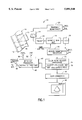
- FIG. 1 is a block diagram of a pulse Doppler ultrasound system that is adapted to carry out the invention.
- FIG. 2 is a logic flow diagram which illustrates the procedure of the invention.
- Ultrasound imaging system 10 includes a transducer array 12 which, during each transmission event, produces a burst of ultrasound energy that is directed into a body 14.
- transducer array 12 is enabled to change its focal plane within body 14.
- flow in fluid pathways 16 and 18 can be imaged by placing the focal plane at a distance d1 or d2 from transducer array 12.
- pulsed Doppler ultrasound relies upon phase and/or time changes in the backscatter signal which result from the interaction of the transmitted ultrasound pulses and the fluids moving in pathways 16 and 18.
- the pulsed Doppler ultrasound transmission signals are produced in transmission/beamformer module 20 and pass through transmission/receive switch 22 to transducer 12.
- Received backscatter signals are passed from transducer 12 through transmission/receive switch 22 to a preamplifier 24 and then through a variable gain amplifier 26 to an analog to digital (A/D) converter 28.
- the digital sample values produced by A/D converter 28 are passed to receiver/beam former processor 30.
- frequency and PRF parameter inputs enable receiver/beamformer processor 30 to convert the received digital sample values to coherent ultrasound signal lines that are passed to color flow velocity processor 32.
- receiver/beamformer processor 30 when passed to color flow velocity processor 32, is processed to enable derivation of the velocities of the fluids passing through an imaged pathway (e.g., 16 and/or 18).
- a velocity-to-color map 34 is accessed which associates particular colors with particular velocities.
- use of velocity-to-color map 34 enables a color associated with the calculated velocity to be assigned to the region evidencing the velocity.
- color flow velocity processor 32 Also stored in color flow velocity processor 32 is a PRF calculation procedure 36 which is utilized to alter the PRF when the transmission frequency is changed in response to a change in focal depth. This feature will be described in further detail below.
- the color flow velocities that are calculated within color flow velocity processor 32 enable colors to be assigned, as aforesaid, to flow fields within the ultrasound image.
- the combined image/color assignment are then fed to scan converter 38 which converts the image from polar coordinates to a raster scan image which is then passed to a display 40 for presentation to the user.
- An interface processor 42 is responsive to user inputs to provide corresponding control signals to the various modules within ultrasound imaging system 10. More specifically, a focus depth input 44 enables the user to alter the focal plane of the transmitted ultrasound beam produced by transducer array 12. A further input control is region of interest (ROI) box input 46 which enables the user to position a box on display 40 which surrounds an area wherein the flow velocities are to be color imaged. The ROI box input 46 and focus depth input 44 are then utilized by interface processor 42 to alter the focal plane of the beam emanating from transducer 12 so as to enable color flow imaging of velocity fields present in the ROI box.
- ROI region of interest
- a depth-to-frequency map 48 is accessible by interface processor 42 to enable an ultrasound transmission frequency to be selected which will best image a particular focus depth. Accordingly, when a revised focus depth is input, map 48 enables interface processor 42 to output a frequency control signal 50 which causes an alteration of the ultrasound transmission frequency and informs other modules of the new transmission frequency value. Also, as will be described below, interface processor 42 is enabled to output a PRF control signal 52 which causes an alteration of the PRF of the pulsed Doppler ultrasound signals. That output is used to maintain a constancy of color flow presentation, even when the transmission frequency is changed.
- the backscatter of all targets increases.
- the amount of increase is dependent on the type of target.
- backscatter increases more than backscatter from tissue.
- tissue backscatter signals levels are typically much less than tissue backscatter signals, the difference between the blood backscatter signals and tissue backscatter signals decreases.
- the increase in blood backscatter and decrease in the difference between blood and tissue backscatter causes a desirable decrease in the dynamic range.
- the negative aspects which result from the use of a higher transmission frequency are a decrease in signal penetration and a change in velocity scale.
- the positive aspect is that blood flow signals, which would have fallen below the minimum detectable values of A/D converter 28, no longer do so and the decrease in dynamic range presents less demands upon the A/D conversion process.
- velocity is proportional to the ratio of the PRF to the transmission frequency.
- the invention automatically adjusts the PRF to retain the same or substantially the same ratio to the transmission frequency as previously.
- the computed velocity value therefore remains unchanged. Given an unchanged velocity value, a prior assigned mapping of velocities to colors will also remain unchanged.
- the system stores a velocity ratio (R max ) that is equal to the ratio of the current PRF to the current transmission frequency (box 50).
- R max a velocity ratio
- interface processor 42 determines a maximum required penetration depth required of a transmitted ultrasound signal (box 54). Then, interface processor 42 selects from depth-to-frequency map 48, a maximum frequency which will provide an optimum level of backscatter at the maximum penetration depth (box 56).
- Interface processor 42 based upon the selected maximum transmission frequency, now outputs a gain control signal to variable gain amplifier 26. That signal alters the gain of amplifier 26 to compensate for any transmit amplitude changes at the new frequency and/or any received amplitude changes resulting from the new frequency selection (box 58).
- interface processor 42 automatically alters PRF output control signal 52 to vary the PRF in a manner as to maintain the ratio of PRF to transmission frequency equal to R max (box 60). Accordingly, the adjustment of the PRF value enables the retention of the previous PRF-to-transmission frequency ratio and maintains a constancy of calculated velocity values.
- the constancy of calculated velocity values assures unchanged color presentations, based on the relationships that are set out in velocity-to-color map 34.
- the sector ROI depth is cropped so that only flows within the cropped sector ROI depth are those which can be subjected to the colorflow imaging procedure at the selected PRF (box 64).
- ultrasound imaging system 10 is able to automatically adjust the transmission frequency and receive gain to a highest detectable frequency. Such adjustment occurs without changing the color presentations that are displayed with respect to fluid flow velocities in a region being imaged. Further, color to velocity mapping remains unchanged, notwithstanding changes in focal plane depth
Abstract
Description
Velocity≈PRF/transmission frequency
Claims (10)
v≈prf/frequency.
v≈prf/frequency.
Priority Applications (1)
| Application Number | Priority Date | Filing Date | Title |
|---|---|---|---|
| US09/025,350 US5891040A (en) | 1998-02-18 | 1998-02-18 | Method for maintaining a constant velocity to color map in an ultrasound flow imaging system |
Applications Claiming Priority (1)
| Application Number | Priority Date | Filing Date | Title |
|---|---|---|---|
| US09/025,350 US5891040A (en) | 1998-02-18 | 1998-02-18 | Method for maintaining a constant velocity to color map in an ultrasound flow imaging system |
Publications (1)
| Publication Number | Publication Date |
|---|---|
| US5891040A true US5891040A (en) | 1999-04-06 |
Family
ID=21825503
Family Applications (1)
| Application Number | Title | Priority Date | Filing Date |
|---|---|---|---|
| US09/025,350 Expired - Fee Related US5891040A (en) | 1998-02-18 | 1998-02-18 | Method for maintaining a constant velocity to color map in an ultrasound flow imaging system |
Country Status (1)
| Country | Link |
|---|---|
| US (1) | US5891040A (en) |
Cited By (17)
| Publication number | Priority date | Publication date | Assignee | Title |
|---|---|---|---|---|
| US6159151A (en) * | 1997-11-18 | 2000-12-12 | U.S. Philips Corporation | Method for the processing of signals relating to an object having moving parts and echographic device for carrying out this method |
| US6354997B1 (en) * | 1997-06-17 | 2002-03-12 | Acuson Corporation | Method and apparatus for frequency control of an ultrasound system |
| US6413218B1 (en) * | 2000-02-10 | 2002-07-02 | Acuson Corporation | Medical diagnostic ultrasound imaging system and method for determining an acoustic output parameter of a transmitted ultrasonic beam |
| US6577967B2 (en) * | 1998-12-31 | 2003-06-10 | General Electric Company | Automatic adjustment of velocity scale and pulse repetition frequency for doppler ultrasound spectrograms |
| US20060058677A1 (en) * | 2002-04-26 | 2006-03-16 | Kazutaka Okada | Ultrasonograph |
| US20070038083A1 (en) * | 2005-08-12 | 2007-02-15 | Siemens Medical Solutions Usa, Inc. | Automatic velocity scale identification for medical diagnostic ultrasound |
| US20070066896A1 (en) * | 2005-09-22 | 2007-03-22 | Constantine Simopoulos | Phase unwrapped velocity display for ultrasound medical imaging |
| US20070078347A1 (en) * | 2005-09-30 | 2007-04-05 | Siemens Medical Solutions Usa, Inc. | Ultrasound color flow imaging at high frame rates |
| US20080269610A1 (en) * | 2007-04-25 | 2008-10-30 | General Electric Company | Method and apparatus for automatic optimization of scanning parameters for ultrasound imaging |
| US20080267467A1 (en) * | 2007-04-30 | 2008-10-30 | General Electric Company | Method and system for automatic adjustment of a diagnostic imaging display |
| US20090149758A1 (en) * | 2000-12-13 | 2009-06-11 | Leonard Smith | Gain Setting in Doppler Haemodynamic Monitors |
| EP2116187A1 (en) * | 2008-05-08 | 2009-11-11 | Olympus Medical Systems Corporation | Ultrasound observation apparatus |
| US20110094288A1 (en) * | 2009-10-14 | 2011-04-28 | Yoav Medan | Mapping ultrasound transducers |
| US9177543B2 (en) | 2009-08-26 | 2015-11-03 | Insightec Ltd. | Asymmetric ultrasound phased-array transducer for dynamic beam steering to ablate tissues in MRI |
| US20170071567A1 (en) * | 2015-09-16 | 2017-03-16 | Toshiba Medical Systems Corporation | Ultrasound diagnosis apparatus |
| US9852727B2 (en) | 2010-04-28 | 2017-12-26 | Insightec, Ltd. | Multi-segment ultrasound transducers |
| US20200138410A1 (en) * | 2018-11-02 | 2020-05-07 | Konica Minolta, Inc. | Ultrasonic diagnostic apparatus |
Citations (7)
| Publication number | Priority date | Publication date | Assignee | Title |
|---|---|---|---|---|
| US3883871A (en) * | 1973-03-12 | 1975-05-13 | Randolph G Moore | Method and modulation system for ambiguity reduction in pulsed radar |
| US4794933A (en) * | 1986-09-29 | 1989-01-03 | Kabushiki Kaisha Toshiba | Ultrasonic blood stream observing apparatus |
| US4799490A (en) * | 1986-03-04 | 1989-01-24 | Aloka Co., Ltd. | Doppler ultrasonic diagnostic apparatus |
| US4819652A (en) * | 1985-02-08 | 1989-04-11 | University Patents, Inc. | C W and pulse Doppler diagnostic system |
| US5107841A (en) * | 1989-11-27 | 1992-04-28 | Acoustic Imaging Technologies Corporation | Maximum entropy velocity estimator for ultrasonic flow imaging system |
| US5549111A (en) * | 1994-08-05 | 1996-08-27 | Acuson Corporation | Method and apparatus for adjustable frequency scanning in ultrasound imaging |
| US5709209A (en) * | 1996-03-29 | 1998-01-20 | Siemens Medical Systems, Inc. | Ultrasound signal processing system |
-
1998
- 1998-02-18 US US09/025,350 patent/US5891040A/en not_active Expired - Fee Related
Patent Citations (7)
| Publication number | Priority date | Publication date | Assignee | Title |
|---|---|---|---|---|
| US3883871A (en) * | 1973-03-12 | 1975-05-13 | Randolph G Moore | Method and modulation system for ambiguity reduction in pulsed radar |
| US4819652A (en) * | 1985-02-08 | 1989-04-11 | University Patents, Inc. | C W and pulse Doppler diagnostic system |
| US4799490A (en) * | 1986-03-04 | 1989-01-24 | Aloka Co., Ltd. | Doppler ultrasonic diagnostic apparatus |
| US4794933A (en) * | 1986-09-29 | 1989-01-03 | Kabushiki Kaisha Toshiba | Ultrasonic blood stream observing apparatus |
| US5107841A (en) * | 1989-11-27 | 1992-04-28 | Acoustic Imaging Technologies Corporation | Maximum entropy velocity estimator for ultrasonic flow imaging system |
| US5549111A (en) * | 1994-08-05 | 1996-08-27 | Acuson Corporation | Method and apparatus for adjustable frequency scanning in ultrasound imaging |
| US5709209A (en) * | 1996-03-29 | 1998-01-20 | Siemens Medical Systems, Inc. | Ultrasound signal processing system |
Cited By (27)
| Publication number | Priority date | Publication date | Assignee | Title |
|---|---|---|---|---|
| US6354997B1 (en) * | 1997-06-17 | 2002-03-12 | Acuson Corporation | Method and apparatus for frequency control of an ultrasound system |
| US6159151A (en) * | 1997-11-18 | 2000-12-12 | U.S. Philips Corporation | Method for the processing of signals relating to an object having moving parts and echographic device for carrying out this method |
| US6577967B2 (en) * | 1998-12-31 | 2003-06-10 | General Electric Company | Automatic adjustment of velocity scale and pulse repetition frequency for doppler ultrasound spectrograms |
| US6413218B1 (en) * | 2000-02-10 | 2002-07-02 | Acuson Corporation | Medical diagnostic ultrasound imaging system and method for determining an acoustic output parameter of a transmitted ultrasonic beam |
| US20090149758A1 (en) * | 2000-12-13 | 2009-06-11 | Leonard Smith | Gain Setting in Doppler Haemodynamic Monitors |
| US8075485B2 (en) * | 2000-12-13 | 2011-12-13 | Deltex Medical Limited | Gain setting in doppler haemodynamic monitors |
| US20060058677A1 (en) * | 2002-04-26 | 2006-03-16 | Kazutaka Okada | Ultrasonograph |
| US8043220B2 (en) * | 2002-04-26 | 2011-10-25 | Hitachi Medical Corporation | Ultrasonograph |
| US20070038083A1 (en) * | 2005-08-12 | 2007-02-15 | Siemens Medical Solutions Usa, Inc. | Automatic velocity scale identification for medical diagnostic ultrasound |
| US7887484B2 (en) | 2005-08-12 | 2011-02-15 | Siemens Medical Solutions Usa, Inc. | Automatic velocity scale identification for medical diagnostic ultrasound |
| US7682311B2 (en) * | 2005-09-22 | 2010-03-23 | Siemens Medical Solutions Usa, Inc. | Phase unwrapped velocity display for ultrasound medical imaging |
| US20070066896A1 (en) * | 2005-09-22 | 2007-03-22 | Constantine Simopoulos | Phase unwrapped velocity display for ultrasound medical imaging |
| US20070078347A1 (en) * | 2005-09-30 | 2007-04-05 | Siemens Medical Solutions Usa, Inc. | Ultrasound color flow imaging at high frame rates |
| US7946990B2 (en) * | 2005-09-30 | 2011-05-24 | Siemens Medical Solutions Usa, Inc. | Ultrasound color flow imaging at high frame rates |
| US20080269610A1 (en) * | 2007-04-25 | 2008-10-30 | General Electric Company | Method and apparatus for automatic optimization of scanning parameters for ultrasound imaging |
| US20080267467A1 (en) * | 2007-04-30 | 2008-10-30 | General Electric Company | Method and system for automatic adjustment of a diagnostic imaging display |
| CN101978932B (en) * | 2008-05-08 | 2013-02-06 | 奥林巴斯医疗株式会社 | Ultrasound observation apparatus |
| US8123690B2 (en) | 2008-05-08 | 2012-02-28 | Olympus Medical Systems Corp. | Ultrasound observation apparatus |
| EP2116187A1 (en) * | 2008-05-08 | 2009-11-11 | Olympus Medical Systems Corporation | Ultrasound observation apparatus |
| US9177543B2 (en) | 2009-08-26 | 2015-11-03 | Insightec Ltd. | Asymmetric ultrasound phased-array transducer for dynamic beam steering to ablate tissues in MRI |
| US20110094288A1 (en) * | 2009-10-14 | 2011-04-28 | Yoav Medan | Mapping ultrasound transducers |
| US8661873B2 (en) * | 2009-10-14 | 2014-03-04 | Insightec Ltd. | Mapping ultrasound transducers |
| US9412357B2 (en) | 2009-10-14 | 2016-08-09 | Insightec Ltd. | Mapping ultrasound transducers |
| US9852727B2 (en) | 2010-04-28 | 2017-12-26 | Insightec, Ltd. | Multi-segment ultrasound transducers |
| US20170071567A1 (en) * | 2015-09-16 | 2017-03-16 | Toshiba Medical Systems Corporation | Ultrasound diagnosis apparatus |
| US10835200B2 (en) * | 2015-09-16 | 2020-11-17 | Canon Medical Systems Corporation | Ultrasound diagnosis apparatus |
| US20200138410A1 (en) * | 2018-11-02 | 2020-05-07 | Konica Minolta, Inc. | Ultrasonic diagnostic apparatus |
Similar Documents
| Publication | Publication Date | Title |
|---|---|---|
| US5891040A (en) | Method for maintaining a constant velocity to color map in an ultrasound flow imaging system | |
| KR100641589B1 (en) | Method and apparatus for enhancing resolution and sensitivity in color flow ultrasound imaging | |
| US6030344A (en) | Methods and apparatus for ultrasound image quantification | |
| US6478742B1 (en) | PRF adjustment method and apparatus, and ultrasonic wave imaging apparatus | |
| EP1176910B1 (en) | Method and apparatus for automatic vessel tracking in ultrasound imaging | |
| US8036856B2 (en) | Method and apparatus for automatically adjusting spectral doppler gain | |
| US6077226A (en) | Method and apparatus for positioning region of interest in image | |
| US6102859A (en) | Method and apparatus for automatic time and/or lateral gain compensation in B-mode ultrasound imaging | |
| US5910115A (en) | Method and apparatus for coherence filtering of ultrasound images | |
| US5379771A (en) | Ultrasonic imaging apparatus | |
| US6142943A (en) | Doppler ultrasound automatic spectrum optimization | |
| JPH03188841A (en) | Ultrasonic diagnostic device | |
| EP0524774B1 (en) | Ultrasonic doppler imaging apparatus | |
| US6599248B1 (en) | Method and apparatus for ultrasound diagnostic imaging | |
| KR20020096965A (en) | Ultrasonic imaging apparatus | |
| US5383464A (en) | Ultrasonic doppler diagnostic system | |
| US6045507A (en) | Method and apparatus for adaptive color flow optimization | |
| US6120451A (en) | Ultrasound color flow display optimization by adjustment of threshold | |
| JP4117383B2 (en) | Ultrasound imaging device | |
| US5050611A (en) | Ultrasonic imaging apparatus | |
| US20080030581A1 (en) | Multizone Color Doppler Beam Transmission Method | |
| US6001063A (en) | Ultrasonic imaging method and apparatus for providing doppler energy correction | |
| US5081996A (en) | Ultrasonic imaging apparatus | |
| JPH05269129A (en) | Ultrasonic diagnostic device | |
| JP2720711B2 (en) | Ultrasound two-dimensional Doppler blood flow meter |
Legal Events
| Date | Code | Title | Description |
|---|---|---|---|
| AS | Assignment |
Owner name: HEWLETT-PACKARD COMPANY, CALIFORNIA Free format text: ASSIGNMENT OF ASSIGNORS INTEREST;ASSIGNORS:GRENON, STEPHEN M.;GADONNIEX, SHARON A.;SNYDER, RICHARD A.;REEL/FRAME:009205/0330;SIGNING DATES FROM 19980212 TO 19980218 |
|
| AS | Assignment |
Owner name: WHITAKER CORPORATION, THE, DELAWARE Free format text: ASSIGNMENT OF ASSIGNORS INTEREST;ASSIGNORS:DENLINGER, KEITH ROBERT;JAKLIN, RALF;MYER, JOHN MARK;REEL/FRAME:009293/0234;SIGNING DATES FROM 19980521 TO 19980618 |
|
| AS | Assignment |
Owner name: HEWLETT-PACKARD COMPANY, A DELAWARE CORPORATION, C Free format text: MERGER;ASSIGNOR:HEWLETT-PACKARD COMPANY, A CALIFORNIA CORPORATION;REEL/FRAME:010841/0649 Effective date: 19980520 |
|
| AS | Assignment |
Owner name: AGILENT TECHNOLOGIES INC, CALIFORNIA Free format text: ASSIGNMENT OF ASSIGNORS INTEREST;ASSIGNOR:HEWLETT-PACKARD COMPANY;REEL/FRAME:010977/0540 Effective date: 19991101 |
|
| FPAY | Fee payment |
Year of fee payment: 4 |
|
| AS | Assignment |
Owner name: KONINKLIJKE PHILIPS ELECTRONICS N.V., NETHERLANDS Free format text: ASSIGNMENT OF ASSIGNORS INTEREST;ASSIGNOR:AGILENT TECHNOLOGIES, INC.;REEL/FRAME:014662/0179 Effective date: 20010801 |
|
| FPAY | Fee payment |
Year of fee payment: 8 |
|
| AS | Assignment |
Owner name: KONINKLIJKE PHILIPS ELECTRONICS N V, NETHERLANDS Free format text: ASSIGNMENT OF ASSIGNORS INTEREST;ASSIGNOR:AGILENT TECHNOLOGIES, INC.;REEL/FRAME:022835/0572 Effective date: 20090610 |
|
| REMI | Maintenance fee reminder mailed | ||
| LAPS | Lapse for failure to pay maintenance fees | ||
| STCH | Information on status: patent discontinuation |
Free format text: PATENT EXPIRED DUE TO NONPAYMENT OF MAINTENANCE FEES UNDER 37 CFR 1.362 |
|
| FP | Expired due to failure to pay maintenance fee |
Effective date: 20110406 |