US5893403A - Lifting folding door - Google Patents
Lifting folding door Download PDFInfo
- Publication number
- US5893403A US5893403A US08/803,402 US80340297A US5893403A US 5893403 A US5893403 A US 5893403A US 80340297 A US80340297 A US 80340297A US 5893403 A US5893403 A US 5893403A
- Authority
- US
- United States
- Prior art keywords
- panels
- guide
- rails
- folding door
- guiding
- Prior art date
- Legal status (The legal status is an assumption and is not a legal conclusion. Google has not performed a legal analysis and makes no representation as to the accuracy of the status listed.)
- Expired - Lifetime
Links
Images


Classifications
-
- E—FIXED CONSTRUCTIONS
- E06—DOORS, WINDOWS, SHUTTERS, OR ROLLER BLINDS IN GENERAL; LADDERS
- E06B—FIXED OR MOVABLE CLOSURES FOR OPENINGS IN BUILDINGS, VEHICLES, FENCES OR LIKE ENCLOSURES IN GENERAL, e.g. DOORS, WINDOWS, BLINDS, GATES
- E06B9/00—Screening or protective devices for wall or similar openings, with or without operating or securing mechanisms; Closures of similar construction
- E06B9/02—Shutters, movable grilles, or other safety closing devices, e.g. against burglary
- E06B9/06—Shutters, movable grilles, or other safety closing devices, e.g. against burglary collapsible or foldable, e.g. of the bellows or lazy-tongs type
- E06B9/0607—Shutters, movable grilles, or other safety closing devices, e.g. against burglary collapsible or foldable, e.g. of the bellows or lazy-tongs type comprising a plurality of similar rigid closing elements movable to a storage position
- E06B9/0646—Shutters, movable grilles, or other safety closing devices, e.g. against burglary collapsible or foldable, e.g. of the bellows or lazy-tongs type comprising a plurality of similar rigid closing elements movable to a storage position characterised by the relative arrangement of the closing elements in the stored position
- E06B9/0669—Shutters, movable grilles, or other safety closing devices, e.g. against burglary collapsible or foldable, e.g. of the bellows or lazy-tongs type comprising a plurality of similar rigid closing elements movable to a storage position characterised by the relative arrangement of the closing elements in the stored position stored in a zig-zag arrangement
-
- E—FIXED CONSTRUCTIONS
- E05—LOCKS; KEYS; WINDOW OR DOOR FITTINGS; SAFES
- E05D—HINGES OR SUSPENSION DEVICES FOR DOORS, WINDOWS OR WINGS
- E05D15/00—Suspension arrangements for wings
- E05D15/26—Suspension arrangements for wings for folding wings
- E05D15/262—Suspension arrangements for wings for folding wings folding vertically
-
- E—FIXED CONSTRUCTIONS
- E06—DOORS, WINDOWS, SHUTTERS, OR ROLLER BLINDS IN GENERAL; LADDERS
- E06B—FIXED OR MOVABLE CLOSURES FOR OPENINGS IN BUILDINGS, VEHICLES, FENCES OR LIKE ENCLOSURES IN GENERAL, e.g. DOORS, WINDOWS, BLINDS, GATES
- E06B9/00—Screening or protective devices for wall or similar openings, with or without operating or securing mechanisms; Closures of similar construction
- E06B9/02—Shutters, movable grilles, or other safety closing devices, e.g. against burglary
- E06B9/06—Shutters, movable grilles, or other safety closing devices, e.g. against burglary collapsible or foldable, e.g. of the bellows or lazy-tongs type
- E06B9/0607—Shutters, movable grilles, or other safety closing devices, e.g. against burglary collapsible or foldable, e.g. of the bellows or lazy-tongs type comprising a plurality of similar rigid closing elements movable to a storage position
- E06B9/0615—Shutters, movable grilles, or other safety closing devices, e.g. against burglary collapsible or foldable, e.g. of the bellows or lazy-tongs type comprising a plurality of similar rigid closing elements movable to a storage position characterised by the closing elements
- E06B9/0638—Slats or panels
-
- E—FIXED CONSTRUCTIONS
- E05—LOCKS; KEYS; WINDOW OR DOOR FITTINGS; SAFES
- E05Y—INDEXING SCHEME RELATING TO HINGES OR OTHER SUSPENSION DEVICES FOR DOORS, WINDOWS OR WINGS AND DEVICES FOR MOVING WINGS INTO OPEN OR CLOSED POSITION, CHECKS FOR WINGS AND WING FITTINGS NOT OTHERWISE PROVIDED FOR, CONCERNED WITH THE FUNCTIONING OF THE WING
- E05Y2900/00—Application of doors, windows, wings or fittings thereof
- E05Y2900/10—Application of doors, windows, wings or fittings thereof for buildings or parts thereof
- E05Y2900/13—Application of doors, windows, wings or fittings thereof for buildings or parts thereof characterised by the type of wing
- E05Y2900/132—Doors
Definitions
- the present invention relates to a lifting folding door comprising a number of panels hinged together, two primarily vertically extending rails arranged each on one side of the opening to be closed by the door for guiding the panels, a number of guide rails arranged next to each vertically extending rail, said guide rails extending towards the top of each of the vertically extending rails for guiding the panels such that, when moving upward, they are folded together in zigzag fashion in primarily horizontal direction, said panels comprising first guide elements for guiding the panels in the vertically extending rails and a number of second guide elements for guiding the panels in the guide rails, said number of second guide elements being equal to the number of guide rails, said rails being adapted for unequivocally determining the lateral movement and the rotation of the panels.
- Such a lifting door is known from U.S. Pat. No. 3,618,656.
- This known folding door comprises two pairs of panels to which guide rollers, which form the second guide elements, are pivotally connected, which guide rollers guide the panels through respective guide tracks, which are formed by channels. Because of the pivotally connected guide rollers the door can be raised from its extended position to its folded position without placing undue stress on the door operating system.
- the goal of the invention is to provide an alternative lifting folding door which can be opened and closed with high speed.
- second guide elements which are rigidly connected to panels of a folding door are, for example, known from AU-B-20968/92.
- AU-B-20968/92 relates to a lifting door of the type comprising only one guide rail pair for all second guide elements, i.e. for all panels, and this guide rail is not adapted for unequivocally determining the lateral movement and rotation of the panels.
- U.S. Pat. No. 3,618,656 teaches away from using rigidly connected second guide elements in the lifting door type which is the subject of U.S. Pat. No. 3,618,656.
- the lifting folding door according to the invention is preferably provided with selection means for selectively guiding each of the second guide elements into the corresponding guide rail.
- FIG. 1 a schematic perspective view of a lifting folding door according to the present invention, in particular, during its assembly;
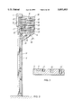
- FIG. 2 a cross section view of the folding door depicted in FIG. 1, in which the rail mounted on one side and the guiding means arranged above it are shown in side view;
- FIG. 3 a cross section along line III--III of FIG. 2;
- FIG. 4 a view of a second embodiment of a lifting door, similar to FIG. 2;
- FIG. 5 a perspective detail view of a third embodiment of the lifting folding door according to the invention.
- FIG. 6 a cross-section view of a fourth embodiment of the invention.
- FIG. 7 a detailed view of the embodiment depicted in FIG. 6;
- FIG. 8 a cross section of a fifth embodiment of the invention.
- FIG. 9 a cross section of one variant of an embodiment represented in FIG. 4;
- FIG. 10 a detailed view partially broken away of the variant shown in FIG. 9;
- FIG. 11 a view of the partially broken away variant shown in FIGS. 9 and 10;
- FIG. 12 a detailed view of the embodiment shown in FIG. 9;
- FIG. 13 a detailed view of steps to prevent skewing
- FIG. 14 a variant of the embodiment shown in FIG. 4;
- FIG. 15 a variant of the embodiment shown in FIG. 5.
- FIG. 1 shows a wall 1, in which an opening 2 is made, which must be closed by a lifting folding door according to the present invention.
- the lifting folding door in its entirety is indicated by 3.
- the lifting folding door contains two rails 4, 5, each arranged at one side of the opening 2, while guiding means 6, 7 are arranged at the top of each of the rails 4, 5 in the form of plates in which appropriate channels are made.
- the lifting folding door further contains panels 8, indicated by broken lines in FIG. 1, which in the opened condition of the door are folded together between the guiding means 6, 7, as depicted in FIG. 1.
- the guiding means 6, 7 are installed in an assembly unit 9, likewise indicated by broken lines.
- This assembly unit is secured to the wall 1 by means of cheeks 10.
- FIG. 1 shows how such a unit is mounted. This shall be later clarified in the description.
- FIG. 2 shows the rail 4, as seen form the opening 2, together with the guide element 6 placed above it.
- a track Arranged in the rail 4 is a track in the form of a channel 11. Pins that are connected to the panels 8 are guided in channel 11.
- the door contains six panels 8, each of which can be folded together in zigzag fashion, being provided with an outer hinge 12 on one side, and each being joined to an inner hinge 13 at the inside.
- the placement of the inner and outer hinges 12, 13 is such that, when the door is folded, the outer hinges remain on the outside of the door and the inner hinges end up on the inside of the door.
- the outer hinges 12 are each joined to a pin, which is guided by channel 11.
- each of the outer hinges 12 is provided with a corresponding pin at its other side, which is guided by a rail present at the outer side of the door opening, in which a corresponding channel is made.
- the upper panel 8 provided with a guide pin 18, 19, 20 likewise extends into the channel 11.
- the respective pins 18, 19, 20 must bend in order to guarantee a good folding action.
- the guiding means 6 designed in the form of a plate are provided with deflection tracks in the form of channels 15, 16, 17.
- the channel 11, i.e., the main track is made broad, as are the pins which are fastened to the outer hinges 12.
- the deflection channels 15, 16, 17 are made more narrow, thus preventing the broad pins from getting into the deflection channels. This is evident in FIG. 3.
- the deflection channels 15, 16, 17 are made more narrow than the channel 11.
- the pins 18, 19, 20 are more narrow than the guide pins that are joined to the outer hinges 12.
- the deflection channels 15, 16, 17 are deeper than the channel 11 at the location of the guide means.
- the channel 11 in the rails 3, 4 is, naturally, just as deep as channel 17, because the respective pin must also be guided through this channel. The differing depth accomplishes an effect such that the pin 18 is guided in the channel 17 during the upward movement, as are subsequently the pin 19 in the channel 16 and pin 20 in channel 15, thus accomplishing the required effect.
- the pins 18, 19, 20 are arranged on the panels 8. It is, of course, just as possible to fasten the pins to the innermost hinges 13. Furthermore, it is possible to execute the device in negative manner. That is, the pins connected to the inner hinges 12 and the guide pins 18, 19, 20 can be replaced by forklike structures, which are guided along guideways. Once again, it is possible to work with differing thickness and/or depths.
- the pins 18, 19, 20 are always arranged on the uppermost panels of each pair. It is, of course, equally possible to fasten the pins to the lowermost panels, or to fasten them to the inner hinges 13. This also applies to the other embodiments.
- FIG. 4 shows an embodiment that is especially suitable for higher speeds; each of the pins always has its own guideway here.
- the inner hinges 13 in this embodiment are each connected to the pins 20, 19, 18, respectively, and each of the pins travels in a separate channel 23, 22, 21, respectively, which are shaped so that the required action is achieved.
- the panels form pairs of different width; it is, of course, possible to adapt panels with the same width.
- the guide pins would have to be fastened to the panels.
- the channels 21, 22 and 23 point outwardly at their underside, in order to force the panels 8 in their closed position outwardly against a seal, not shown in the drawing.
- FIG. 5 shows an arrangement in which the selection of the pins occurs by means of "points" or switches in the form of switch elements.
- this embodiment contains a track in the form of a channel 24, that is intended exclusively for the guiding of the pins 18, 19, 20, connected to the panels 8, or inner hinges 13.
- the pins connected to the outer hinges 12 move along a channel not shown in the present figure.
- a switch element 28 is arranged at the point where the deflection channel 25 branches off from the main channel 24, a switch element 28 is arranged.
- the moving pin By maintaining the switch element in the indicated position, the moving pin will follow the main channel, while in the other position with the deflection element 28, as represented for the deflection channel 26, the pin will follow the deflection channel.
- a mechanism comprised of a cam 30, which is placed in the deflection channel located above the particular deflection channel, and which is joined to the deflection unit 28 by means of a lever system 31.
- a spring 32 In order to hold the deflection element 28 in its normal indicated position, there is a spring 32. This means that, whenever the particular pin travels in a deflection element, the particular cam is operated, thus moving the deflection element from the channel located underneath to the deflection position.
- the channel 11 here is not provided with branches, and there are no separate guide elements present for the inner hinges, or guide pins connected to the panels 8 in the vicinity of the inner hinges 13. Instead, the upper portion of the channel 11 is provided with enlargements 37, while the upper panel of each pair of panels 8 is joined to a cam 38 at the outer hinges 12. In other words, the cam 38 for turning about the hinge 12 is rigidly connected to the lower panel 8 of the pair of panels that the outer hinge 12 is connected to.
- the particular cam structure is shown in greater detail in FIG. 7.
- the cam 38 is provided with rounding 40 at its head end, while the enlargement 37 is also provided with rounding 41.
- the roundings 40 and 41 serve to facilitate the turning of the cam 38 in the enlargement 37.
- a lifting mechanism is present in this embodiment in the form of a cord 42, which is connected at the lower end to the lower end of the lowermost panel 8, being guided through a guide pulley 43 above the position of the uppermost panel 8 and wound on a winding drum 44, which is operated by means of an electric motor 45, for example.
- a lifting mechanism must also be present in the previously explained embodiments.
- other lifting mechanisms can be used, e.g., a circular chain or a hand-operated lifting mechanism. This applies to all sample embodiments, of course.
- the cord 42 is not connected to the hinges. However, it is possible to guide the cord 42 in zigzag fashion around the hinges 13 and 12, so that the cord exerts the respective folding forces. It is then possible to eliminate the tension springs 39.
- tension springs 39 are arranged between each pair of panels. Of course, it is possible to leave out one pair of each set of springs 39.
- the embodiment shown in FIG. 8 largely coincides with the embodiment shown in FIG. 2.
- the embodiment shown in FIG. 8 differs in that the channel 11 is provided with enlargements, indicated by 48, at the place where the deflection channels diverge from the channel 11. These enlargements have the purpose of making the deflection of the pins and, thus, the panels more gradual than that in the former embodiment, discussed by means of FIG. 2.
- a draw spring 39 is arranged between each pair of panels, in order to ensure that the pins and, thus, the panels follow the deflection track and fold together. In order to guide the pins into the proper tracks under these forces directed toward the diverging channels, the depth of the respective channels is reversed; thus, the channel 15 is the least deep in the embodiment of FIG.
- channel 16 is somewhat deeper than channel 15, and channel 17 is the deepest.
- the main channel 11 is the most deep, in order to prevent the pins connected to the outer hinges 12 from moving into the diverging channels. It is also possible, as in the embodiment of FIG. 2, to make these pins thicker.
- the embodiment depicted in FIG. 9 agrees in most respects with the embodiment shown in FIG. 4, but differs in that the guide pins 18, 19, 20 are provided with guide wheels 48, 49, 50, respectively. Furthermore, the guide pins are joined to the panels 8 by means of arms 51, 52, 53, respectively. The guide wheels ensure a better guidance in the separate tracks 21, 22, 23, respectively, so that the movement occurs with less friction.
- the guide pins 12 arranged on the outside are also provided with guide wheels 54.
- the embodiment further differs in that an odd number of panels 8 is employed, and the top side of the uppermost panel is folded inward.
- FIG. 10 shows the structure of the panels in more detail.
- Each of the panels 8 is formed by a sandwich structure with an inner wall 55 and an outer wall 56, between which is filler material 57 in the form of a plastic foam.
- the panel is closed by a profile 58 and, as shown in the drawing, constructed as a unit with the inner wall by means of, e.g., pop rivets, a screw connection, or by means of welding or gluing.
- Each panel is closed at its upper end by means of a similar profile 58.
- a rubber profile 59 that is provided with a protuberance 60 which is exactly fitted to each of the profiles 58.
- the profiles 58 are provided with an indentation 61.
- the profile 59 can be joined to one of the profiles 58 by means of vulcanization or gluing, for example. Thus, a good seal is achieved in the closed condition.
- hinges 62 For joining together the panels, use is made of hinges 62, the leaves of which are joined by means of screws 63 to the profiles 58.
- the profile 59 is partly cut away at the hinges. This ensures that no additional space is needed for the hinges, while a good seal is achieved by keeping part of one edge 64 of the closing profile.
- FIG. 11 The arrangement according to the above embodiment is shown from the exterior in FIG. 11. It follows from this that an even number of panels is employed in this embodiment, but it is constructed such that the upper end of the uppermost panel folds inward, as does the lower end of the lowermost panel. For this, an extra guide rail 65 is mounted, extending entirely downward. All of this is shown in detail in FIG. 12. It is noted that the depicted embodiment is fit for an odd number of panels. Therefore, the upper panel comprises an extra guide pin 51 which is guided in guide element 21. This offers further the possibility to give the upper panel a more limited heigth. Moreover, an extra arm 66 with an extra guide pin 67 on it is installed, of course.
- the guide wheels 48, 49, 50 are replaced by balls. This has the advantage that they can turn in any direction, so that the friction against both the sides and the bottom of the rail is as little as possible. Of course, it is difficult to mount a ball. It is also possible in theory to employ a V-shaped rail, in which the ball makes constant contact at two points. This simplifies the bearing problem of the ball.
- FIG. 13 shows a detailed view of a device for preventing skewing of the panels of the lifting folding door.
- This arrangement is formed by an arm 68, which is connected by means of a hinge 69 to one of the panels 8.
- a bushing 70 Fastened to the arm is a bushing 70, in which a pin 71 is springloaded in the axial direction.
- the pin 71 is connected to a fork 72, through the outer ends of which an axle 73 is arranged, on which a wheel 74 is mounted.
- the wheel 74 turns against the head wall of one of the channels 21, 22, or 23, or in the main channel 11 itself.
- FIG. 14 shows a different variant, in which, in order to prevent the outside of the elements from moving downward during the folding of the elements, supports are arranged in the form of U-shaped elements 75.
- a cavity 76 is made, being outwardly rounded at its lower end.
- a pin 77 is arranged, which engages with the cavity and basically prevents the front of the panels from moving downward.
- they fulfill a certain guiding function.
- suitable recesses are made at the pins 77 in the panels located above them.
- the action is improved by creating a certain clamping action of the pins 77 in the cavity 76. This is accomplished, for example, by lining the cavity 76 with material having a large coefficient of friction, for example, rubber. Moreover, it is important that the pins 77 and the elements 75 of each of the panels are placed at different distances from the edges of the door opening, in order to prevent the pins of different distances from the edges of the door opening, in order to prevent the pins of different panels being hindered by the elements 75 of pins belonging to other panels.
- a shoe 78 is arranged in the upper part 24 of the channel, acting as a closing element or movable switch.
- the shoe 78 is adjustable in height and provides connections to different deflection tracks at different positions.
- actuation is possible by means of cables that are fastened, e.g., to the lowermost panel.
- a cable is fastened to the panel on either side of the closed opening.
- these cables also form a selection mechanism.
- the cables can each be wound on a single drum or on a pair of drums located at one side of the door. One of the cables should then be guided over the aperture of the door. This obviates the need for a through going shaft.
- an assembly unit 9 is brought up, for example, on a truck 35, which is provided with a platform 36 that can rise and turn.
- the aforesaid assembly unit 9 is placed on this platform 36, whereupon the truck 35 is driven into the opening which is to be closed, the platform 36 is moved upward and turned until the assembly unit 9 located on it has reached the correct position, and this is secured in place by means of the cheeks 10 and a suitable fastening material.
- the rails 4, 5 which are brought up separately, are put in place and fastened, after which, after affixing the various operating elements, the connection of the power supply, and so forth, the unit can be placed in operation. After this, the truck 35 can be taken away.
- a liftable platform it is possible for instance to make use of a fork-lift truck.
- a hoisting crane it is possible to use other lifting or hoisting mechanisms, for instance a hoisting crane.
- means will have to be provided to couple the mounting unit to the hoisting crane, for instance by means of a levelling rod.
Abstract
Description
Claims (10)
Applications Claiming Priority (5)
| Application Number | Priority Date | Filing Date | Title |
|---|---|---|---|
| NL9401556A NL9401556A (en) | 1994-09-23 | 1994-09-23 | Vertically folding door |
| NL9401556 | 1994-09-23 | ||
| NL9500106A NL9500106A (en) | 1994-09-23 | 1995-01-20 | Lift folding door. |
| NL9500106 | 1995-01-20 | ||
| PCT/NL1995/000317 WO1996009457A1 (en) | 1994-09-23 | 1995-09-22 | Lifting folding door |
Related Parent Applications (1)
| Application Number | Title | Priority Date | Filing Date |
|---|---|---|---|
| PCT/NL1995/000317 Continuation WO1996009457A1 (en) | 1994-09-23 | 1995-09-22 | Lifting folding door |
Publications (1)
| Publication Number | Publication Date |
|---|---|
| US5893403A true US5893403A (en) | 1999-04-13 |
Family
ID=27352465
Family Applications (1)
| Application Number | Title | Priority Date | Filing Date |
|---|---|---|---|
| US08/803,402 Expired - Lifetime US5893403A (en) | 1994-09-23 | 1997-02-20 | Lifting folding door |
Country Status (1)
| Country | Link |
|---|---|
| US (1) | US5893403A (en) |
Cited By (18)
| Publication number | Priority date | Publication date | Assignee | Title |
|---|---|---|---|---|
| US20030046870A1 (en) * | 1999-04-14 | 2003-03-13 | Guido Langenbach | Crash protection device |
| US6615898B2 (en) | 2001-05-30 | 2003-09-09 | Rite-Hite Holding Corporation | Release mechanism for a sectional door |
| US6651724B1 (en) * | 1999-07-01 | 2003-11-25 | Antonio Cittadini | Folding blinds for windows and doors |
| US20080210388A1 (en) * | 2003-01-30 | 2008-09-04 | Parma Shutter Technologies Ltd | Stacking mechanism |
| EP2000620A1 (en) * | 2007-06-05 | 2008-12-10 | BUBENDORFF Société Anonyme | Deployable structure |
| US20100287840A1 (en) * | 2009-05-15 | 2010-11-18 | Vladimir Godovalov | Sectional folding up garage door |
| US20110041407A1 (en) * | 2008-02-15 | 2011-02-24 | Hunter Douglas Industries Bv | Louver rotating mechanism |
| US20110253322A1 (en) * | 2008-12-24 | 2011-10-20 | Marco Fanizzi | Foldaway security shutter |
| US20120124917A1 (en) * | 2007-12-13 | 2012-05-24 | Judd Jackson | Retractable Load-Bearing Cover |
| US9637964B1 (en) * | 2015-12-29 | 2017-05-02 | Cmech (Guangzhou) Ltd. | Cupboard with up-down louvered door and balance system |
| US9637966B1 (en) * | 2015-12-29 | 2017-05-02 | Cmech (Guangzhou) Ltd. | Cupboard with up-down louvered door |
| USD855438S1 (en) | 2018-03-22 | 2019-08-06 | Clopay Building Products Company, Inc. | Garage door cam |
| WO2019204250A1 (en) * | 2018-04-17 | 2019-10-24 | Clopay Building Products Company, Inc. | High-speed sectional door |
| USD896616S1 (en) | 2018-03-22 | 2020-09-22 | Clopay Building Products Company, Inc. | Garage door cam |
| US10871021B2 (en) | 2015-12-29 | 2020-12-22 | Cmech (Guangzhou) Ltd. | Cupboard door balance system |
| US11156029B2 (en) * | 2016-06-24 | 2021-10-26 | Rolflex Exploitatie B.V. | Sectional folding overhead door assembly |
| US20220098912A1 (en) * | 2020-09-30 | 2022-03-31 | Cornellcookson, Llc | Vertically stacking panel door with cam levers |
| US20220170303A1 (en) * | 2020-09-30 | 2022-06-02 | Cornellcookson, Llc | Vertically stacking panel door with cam levers and improved ramps |
Citations (9)
| Publication number | Priority date | Publication date | Assignee | Title |
|---|---|---|---|---|
| BE501927A (en) * | ||||
| US3280888A (en) * | 1963-12-23 | 1966-10-25 | Wilbur A Davis | Folding overhead door |
| US3618656A (en) * | 1969-12-08 | 1971-11-09 | Pamela A Young | Folding door apparatus |
| US4374537A (en) * | 1979-10-31 | 1983-02-22 | Charles Lindbergh | Collapsing closure system and operating mechanism |
| US4379478A (en) * | 1980-06-09 | 1983-04-12 | Dale Lichy | Folding overhead doors |
| US4460030A (en) * | 1982-09-29 | 1984-07-17 | Chamberlain Manufacturing Corporation | Collapsible garage door |
| US4538661A (en) * | 1983-08-09 | 1985-09-03 | Chamberlain Manufacturing Corporation | Garage door operator and method of assembling |
| US4603723A (en) * | 1983-10-18 | 1986-08-05 | Kyoritsu Kikai Co., Ltd. | Shutter |
| WO1990013727A1 (en) * | 1989-05-05 | 1990-11-15 | Edgar Griebel | Vertically opening sectional door |
-
1997
- 1997-02-20 US US08/803,402 patent/US5893403A/en not_active Expired - Lifetime
Patent Citations (9)
| Publication number | Priority date | Publication date | Assignee | Title |
|---|---|---|---|---|
| BE501927A (en) * | ||||
| US3280888A (en) * | 1963-12-23 | 1966-10-25 | Wilbur A Davis | Folding overhead door |
| US3618656A (en) * | 1969-12-08 | 1971-11-09 | Pamela A Young | Folding door apparatus |
| US4374537A (en) * | 1979-10-31 | 1983-02-22 | Charles Lindbergh | Collapsing closure system and operating mechanism |
| US4379478A (en) * | 1980-06-09 | 1983-04-12 | Dale Lichy | Folding overhead doors |
| US4460030A (en) * | 1982-09-29 | 1984-07-17 | Chamberlain Manufacturing Corporation | Collapsible garage door |
| US4538661A (en) * | 1983-08-09 | 1985-09-03 | Chamberlain Manufacturing Corporation | Garage door operator and method of assembling |
| US4603723A (en) * | 1983-10-18 | 1986-08-05 | Kyoritsu Kikai Co., Ltd. | Shutter |
| WO1990013727A1 (en) * | 1989-05-05 | 1990-11-15 | Edgar Griebel | Vertically opening sectional door |
Cited By (26)
| Publication number | Priority date | Publication date | Assignee | Title |
|---|---|---|---|---|
| US20030046870A1 (en) * | 1999-04-14 | 2003-03-13 | Guido Langenbach | Crash protection device |
| US6901703B2 (en) | 1999-04-14 | 2005-06-07 | Rite-Hite Holding Corporation | Crash protection device |
| US6651724B1 (en) * | 1999-07-01 | 2003-11-25 | Antonio Cittadini | Folding blinds for windows and doors |
| US6615898B2 (en) | 2001-05-30 | 2003-09-09 | Rite-Hite Holding Corporation | Release mechanism for a sectional door |
| US20080210388A1 (en) * | 2003-01-30 | 2008-09-04 | Parma Shutter Technologies Ltd | Stacking mechanism |
| US7681620B2 (en) * | 2003-01-30 | 2010-03-23 | Parma Shutter Technologies Ltd | Stacking mechanism |
| EP2000620A1 (en) * | 2007-06-05 | 2008-12-10 | BUBENDORFF Société Anonyme | Deployable structure |
| FR2917113A1 (en) * | 2007-06-05 | 2008-12-12 | Bubendorff Sa | DEPLOYABLE STRUCTURE. |
| US8371070B2 (en) * | 2007-12-13 | 2013-02-12 | Wutpool, Inc. | Retractable load-bearing cover |
| US20120124917A1 (en) * | 2007-12-13 | 2012-05-24 | Judd Jackson | Retractable Load-Bearing Cover |
| US20110041407A1 (en) * | 2008-02-15 | 2011-02-24 | Hunter Douglas Industries Bv | Louver rotating mechanism |
| US20110253322A1 (en) * | 2008-12-24 | 2011-10-20 | Marco Fanizzi | Foldaway security shutter |
| US8327908B2 (en) * | 2009-05-15 | 2012-12-11 | Vladimir Godovalov | Sectional folding up garage door |
| US20100287840A1 (en) * | 2009-05-15 | 2010-11-18 | Vladimir Godovalov | Sectional folding up garage door |
| US10871021B2 (en) | 2015-12-29 | 2020-12-22 | Cmech (Guangzhou) Ltd. | Cupboard door balance system |
| US9637964B1 (en) * | 2015-12-29 | 2017-05-02 | Cmech (Guangzhou) Ltd. | Cupboard with up-down louvered door and balance system |
| US9637966B1 (en) * | 2015-12-29 | 2017-05-02 | Cmech (Guangzhou) Ltd. | Cupboard with up-down louvered door |
| US11156029B2 (en) * | 2016-06-24 | 2021-10-26 | Rolflex Exploitatie B.V. | Sectional folding overhead door assembly |
| USD855438S1 (en) | 2018-03-22 | 2019-08-06 | Clopay Building Products Company, Inc. | Garage door cam |
| USD896616S1 (en) | 2018-03-22 | 2020-09-22 | Clopay Building Products Company, Inc. | Garage door cam |
| US11105133B2 (en) | 2018-04-17 | 2021-08-31 | Clopay Building Products Company, Inc. | High-speed sectional door |
| WO2019204250A1 (en) * | 2018-04-17 | 2019-10-24 | Clopay Building Products Company, Inc. | High-speed sectional door |
| US20220098912A1 (en) * | 2020-09-30 | 2022-03-31 | Cornellcookson, Llc | Vertically stacking panel door with cam levers |
| US20220170303A1 (en) * | 2020-09-30 | 2022-06-02 | Cornellcookson, Llc | Vertically stacking panel door with cam levers and improved ramps |
| US11873670B2 (en) * | 2020-09-30 | 2024-01-16 | Cornellcookson, Llc | Vertically stacking panel door with cam levers and ramps |
| US11933094B2 (en) * | 2020-09-30 | 2024-03-19 | Cornellcookson, Llc | Vertically stacking panel door with cam levers |
Similar Documents
| Publication | Publication Date | Title |
|---|---|---|
| US5893403A (en) | Lifting folding door | |
| US6530619B2 (en) | Opening and closing device for sliding vehicle door | |
| US9637966B1 (en) | Cupboard with up-down louvered door | |
| JP2018523031A (en) | Vertical moving gate with gate panel | |
| EP1381746B1 (en) | Universal cable window regulator assembly for vehicles | |
| CA2200694C (en) | Lifting folding door | |
| CN101868708B (en) | Open/close device for pit cover | |
| US5709427A (en) | Vehicle roof with a roof panel that can be pivoted open | |
| DK1176280T3 (en) | Port, especially the garage door | |
| US5275461A (en) | Tilt and slide roof with links | |
| US4589227A (en) | Side window glass regulator for quarter windows on convertibles | |
| JPS5526398A (en) | Garage wherein vehicles are parked at two levels | |
| KR101466467B1 (en) | Opening and closing apparatus for sunroof | |
| JPH078767Y2 (en) | Structure of wire type window regulator | |
| CN214006923U (en) | Vertical-opening overlapped garage door with translation structure | |
| JP3756424B2 (en) | Wire type window regulator | |
| JPH08230726A (en) | Truck | |
| CN217518584U (en) | Sectional cantilever door structure | |
| JP3850588B2 (en) | Vehicle sunroof device | |
| JPH0434090Y2 (en) | ||
| JP3502723B2 (en) | Stepping plate elevating mechanism for horizontal sliding safe vault door | |
| JPH02217582A (en) | Window glass elevator | |
| JPH0230333Y2 (en) | ||
| KR100402866B1 (en) | Apparatus for ascending and descending a door glass of an automobile | |
| KR200226540Y1 (en) | Spare Tire Lift |
Legal Events
| Date | Code | Title | Description |
|---|---|---|---|
| AS | Assignment |
Owner name: ROLFLEX OOST NEDERLAND B.V., NETHERLANDS Free format text: ASSIGNMENT OF ASSIGNORS INTEREST;ASSIGNOR:MEGENS, JOHANNES HENDRIKUS;REEL/FRAME:008429/0096 Effective date: 19970130 |
|
| AS | Assignment |
Owner name: ROLFLEX NEDERLAND B.V., NETHERLANDS Free format text: CHANGE OF NAME;ASSIGNOR:ROLFLEX OOST NEDERLAND B.V.;REEL/FRAME:009417/0649 Effective date: 19970120 |
|
| STCF | Information on status: patent grant |
Free format text: PATENTED CASE |
|
| AS | Assignment |
Owner name: FD MANAGEMENT, INC., DELAWARE Free format text: ASSIGNMENT OF ASSIGNORS INTEREST;ASSIGNOR:CONOPCO, INC.;REEL/FRAME:011474/0546 Effective date: 20010123 |
|
| FPAY | Fee payment |
Year of fee payment: 4 |
|
| FEPP | Fee payment procedure |
Free format text: PAYOR NUMBER ASSIGNED (ORIGINAL EVENT CODE: ASPN); ENTITY STATUS OF PATENT OWNER: SMALL ENTITY |
|
| FPAY | Fee payment |
Year of fee payment: 8 |
|
| FPAY | Fee payment |
Year of fee payment: 12 |