US5894090A - Silicon bulk micromachined, symmetric, degenerate vibratorygyroscope, accelerometer and sensor and method for using the same - Google Patents

Silicon bulk micromachined, symmetric, degenerate vibratorygyroscope, accelerometer and sensor and method for using the same Download PDF

Info

Publication number
US5894090A
US5894090A US08/657,685 US65768596A US5894090A US 5894090 A US5894090 A US 5894090A US 65768596 A US65768596 A US 65768596A US 5894090 A US5894090 A US 5894090A
Authority
US
United States
Prior art keywords
symmetric
resonator
rim
leaf structure
clover
Prior art date
Legal status (The legal status is an assumption and is not a legal conclusion. Google has not performed a legal analysis and makes no representation as to the accuracy of the status listed.)
Expired - Fee Related
Application number
US08/657,685
Inventor
Tony K. Tang
William J. Kaiser
Randall K. Bartman
Jaroslava Z. Wilcox
Roman C. Gutierrez
Robert J. Calvet
Current Assignee (The listed assignees may be inaccurate. Google has not performed a legal analysis and makes no representation or warranty as to the accuracy of the list.)
California Institute of Technology CalTech
Original Assignee
California Institute of Technology CalTech
Priority date (The priority date is an assumption and is not a legal conclusion. Google has not performed a legal analysis and makes no representation as to the accuracy of the date listed.)
Filing date
Publication date
Application filed by California Institute of Technology CalTech filed Critical California Institute of Technology CalTech
Priority to US08/657,685 priority Critical patent/US5894090A/en
Assigned to CALIFORNIA INSTITUTE OF TECHNOLOGY reassignment CALIFORNIA INSTITUTE OF TECHNOLOGY ASSIGNMENT OF ASSIGNORS INTEREST (SEE DOCUMENT FOR DETAILS). Assignors: BARTMAN, RANDALL K., CALVET, ROBERT J., KAISER, WILLIAM J., GUTIERREZ, ROMAN C., TANG, TONY K., WILCOX, JAROSLAVA Z.
Assigned to NATIONAL AERO. AND SPACE ADMINISTRATION reassignment NATIONAL AERO. AND SPACE ADMINISTRATION CONFIRMATORY LICENSE (SEE DOCUMENT FOR DETAILS). Assignors: CALIFORNIA INST. OF TECHNOLOGY
Priority to AU32880/97A priority patent/AU3288097A/en
Priority to PCT/US1997/009021 priority patent/WO1997045702A1/en
Priority to DE69731742T priority patent/DE69731742T2/en
Priority to EP97928679A priority patent/EP0902875B1/en
Application granted granted Critical
Publication of US5894090A publication Critical patent/US5894090A/en
Anticipated expiration legal-status Critical
Expired - Fee Related legal-status Critical Current

Links

Images

Classifications

    • GPHYSICS
    • G01MEASURING; TESTING
    • G01CMEASURING DISTANCES, LEVELS OR BEARINGS; SURVEYING; NAVIGATION; GYROSCOPIC INSTRUMENTS; PHOTOGRAMMETRY OR VIDEOGRAMMETRY
    • G01C19/00Gyroscopes; Turn-sensitive devices using vibrating masses; Turn-sensitive devices without moving masses; Measuring angular rate using gyroscopic effects
    • G01C19/56Turn-sensitive devices using vibrating masses, e.g. vibratory angular rate sensors based on Coriolis forces
    • G01C19/5719Turn-sensitive devices using vibrating masses, e.g. vibratory angular rate sensors based on Coriolis forces using planar vibrating masses driven in a translation vibration along an axis
    • GPHYSICS
    • G01MEASURING; TESTING
    • G01PMEASURING LINEAR OR ANGULAR SPEED, ACCELERATION, DECELERATION, OR SHOCK; INDICATING PRESENCE, ABSENCE, OR DIRECTION, OF MOVEMENT
    • G01P15/00Measuring acceleration; Measuring deceleration; Measuring shock, i.e. sudden change of acceleration
    • G01P15/02Measuring acceleration; Measuring deceleration; Measuring shock, i.e. sudden change of acceleration by making use of inertia forces using solid seismic masses
    • G01P15/08Measuring acceleration; Measuring deceleration; Measuring shock, i.e. sudden change of acceleration by making use of inertia forces using solid seismic masses with conversion into electric or magnetic values
    • G01P15/125Measuring acceleration; Measuring deceleration; Measuring shock, i.e. sudden change of acceleration by making use of inertia forces using solid seismic masses with conversion into electric or magnetic values by capacitive pick-up
    • GPHYSICS
    • G01MEASURING; TESTING
    • G01PMEASURING LINEAR OR ANGULAR SPEED, ACCELERATION, DECELERATION, OR SHOCK; INDICATING PRESENCE, ABSENCE, OR DIRECTION, OF MOVEMENT
    • G01P15/00Measuring acceleration; Measuring deceleration; Measuring shock, i.e. sudden change of acceleration
    • G01P15/14Measuring acceleration; Measuring deceleration; Measuring shock, i.e. sudden change of acceleration by making use of gyroscopes
    • GPHYSICS
    • G01MEASURING; TESTING
    • G01PMEASURING LINEAR OR ANGULAR SPEED, ACCELERATION, DECELERATION, OR SHOCK; INDICATING PRESENCE, ABSENCE, OR DIRECTION, OF MOVEMENT
    • G01P15/00Measuring acceleration; Measuring deceleration; Measuring shock, i.e. sudden change of acceleration
    • G01P15/18Measuring acceleration; Measuring deceleration; Measuring shock, i.e. sudden change of acceleration in two or more dimensions
    • GPHYSICS
    • G01MEASURING; TESTING
    • G01PMEASURING LINEAR OR ANGULAR SPEED, ACCELERATION, DECELERATION, OR SHOCK; INDICATING PRESENCE, ABSENCE, OR DIRECTION, OF MOVEMENT
    • G01P15/00Measuring acceleration; Measuring deceleration; Measuring shock, i.e. sudden change of acceleration
    • G01P15/02Measuring acceleration; Measuring deceleration; Measuring shock, i.e. sudden change of acceleration by making use of inertia forces using solid seismic masses
    • G01P15/08Measuring acceleration; Measuring deceleration; Measuring shock, i.e. sudden change of acceleration by making use of inertia forces using solid seismic masses with conversion into electric or magnetic values
    • G01P2015/0805Measuring acceleration; Measuring deceleration; Measuring shock, i.e. sudden change of acceleration by making use of inertia forces using solid seismic masses with conversion into electric or magnetic values being provided with a particular type of spring-mass-system for defining the displacement of a seismic mass due to an external acceleration
    • G01P2015/0822Measuring acceleration; Measuring deceleration; Measuring shock, i.e. sudden change of acceleration by making use of inertia forces using solid seismic masses with conversion into electric or magnetic values being provided with a particular type of spring-mass-system for defining the displacement of a seismic mass due to an external acceleration for defining out-of-plane movement of the mass
    • G01P2015/084Measuring acceleration; Measuring deceleration; Measuring shock, i.e. sudden change of acceleration by making use of inertia forces using solid seismic masses with conversion into electric or magnetic values being provided with a particular type of spring-mass-system for defining the displacement of a seismic mass due to an external acceleration for defining out-of-plane movement of the mass the mass being suspended at more than one of its sides, e.g. membrane-type suspension, so as to permit multi-axis movement of the mass
    • G01P2015/0842Measuring acceleration; Measuring deceleration; Measuring shock, i.e. sudden change of acceleration by making use of inertia forces using solid seismic masses with conversion into electric or magnetic values being provided with a particular type of spring-mass-system for defining the displacement of a seismic mass due to an external acceleration for defining out-of-plane movement of the mass the mass being suspended at more than one of its sides, e.g. membrane-type suspension, so as to permit multi-axis movement of the mass the mass being of clover leaf shape

Landscapes

  • Physics & Mathematics (AREA)
  • General Physics & Mathematics (AREA)
  • Engineering & Computer Science (AREA)
  • Radar, Positioning & Navigation (AREA)
  • Remote Sensing (AREA)
  • Gyroscopes (AREA)

Abstract

When embodied in a microgyroscope, the invention is comprised of a silicon, four-leaf clover structure with a post attached to the center. The whole structure is suspended by four silicon cantilevers or springs. The device is electrostatically actuated and capacitively detects Coriolis induced motions of the leaves of the leaf clover structure. In the case where the post is not symmetric with the plane of the clover leaves, the device can is usable as an accelerometer. If the post is provided in the shape of a dumb bell or an asymmetric post, the center of gravity is moved out of the plane of clover leaf structure and a hybrid device is provided. When the clover leaf structure is used without a center mass, it performs as a high Q resonator usable as a sensor of any physical phenomena which can be coupled to the resonant performance.

Description

The invention described herein was made in the performance of work under an NASA contract and is subject to provisions of Public Law 9-517 (35 USC 202) in which the contractor has elected to retain title.
BACKGROUND OF THE INVENTION
1. Field of the Invention
The invention relates to silicon bulk micromachined transducers and in particular vibratory symmetric transducers usable as gyroscopes, sensors and accelerometers.
2. Description of the Prior Art
The applications for gyroscopes in guidance and control devices is notorious and has been realized in more recent technologies by means of optical gyroscopes such as ring laser gyroscopes, and fiberoptic gyroscopes as well as vibratory gyroscopes such as hemispherical resonator gyroscopes, tuning fork gyroscopes, and silicon micromachined vibratory gyroscopes.
The advantages of optical gyroscopes include high dynamic range, high band width, rapid start up, little acceleration sensitivity at least to the first order, good day-to-day drift stability and a stable linear scale factor. The ring laser gyroscope and fiberoptic gyroscopes in particular have excellent stability over periods of hours, but are noisy during short term intervals of the duration of several seconds, where they act as white noise generators. High performance optical gyroscopes also require complex electronics support, a path link controller, a high voltage power supply, mechanical dithering, optical modulators, thermoelectric coolers, signal processing, high order modeling, precision optical components and complicated and delicate assembly and manufacturing processes. Each of these requirements increases the cost and power requirements of high performance optical gyroscopes. Moreover, the performance of an optical gyroscope depends directly with the area enclosed within its optical path. Apart from various technical difficulties encountered in attempting to reduce fiberoptic gyroscopes and ring laser gyroscopes to millimeter dimensions, this fundamental scaling law makes it effectively impossible to realize small, high performance optical gyroscopes.
In a vibratory gyroscope, the Coriolis effect induces energy transfer from the driver input vibratory mode to another mode which is sensed or output during rotation of the gyroscope. An example of such a high performance vibratory gyroscope is the hemispherical resonator gyroscope. The hemispherical resonator gyroscope is made of quartz and has a shell resonator design. It is immune to external vibration and is capable of standing high g shocks. However, it requires precise machining of the resonator and housing, high vacuum sealing and gettering, and computer support. The hemispherical resonator gyroscope is very large, difficult to manufacture, expensive and consumes a large amount of power.
Another type of vibratory gyroscope is the quartz tuning fork vibratory gyroscope. This type of gyroscope is insensitive to linear vibration, has low mechanical loss, and is capable of standing high g shock. However, the quartz tuning fork microscope has low responsitivity, high temperature sensitivity, and is not integratable with silicon electronics.
Silicon micromachined vibratory gyroscopes are integratable with silicon electronics. These devices are capable of achieving high Q factors, can withstand high g shocks due to their small masses, are insensitive to linear vibration and consume little power. However, most of these micromachined gyroscopes have a very small rotation response, since their input and output vibration modes have different mode shapes and resonant frequencies. The use of different resonant modes also makes these devices very temperature sensitive due to the different temperature dependency of each of the modes. These devices usually have very high resonant frequencies resulting in low responsitivity, since the Coriolis induced response is inversely proportional to the resonant frequency of the structure. Finally, due to the small mass of the structure, thermal noise limits the ultimate performance and use of microgyroscopes. For these reasons, micromachined vibratory gyroscopes have not been used for spacecraft navigation and attitude control applications, but have been employed primarily for automotive applications in which extreme low cost is a major driving factor and performance is set at a lower premium.
Therefore, what is needed is some type of silicon micromachined vibratory gyroscope, accelerometer or sensor which overcomes each of the shortcomings of the prior art. In particular, what is needed is a silicon micromachined vibratory microgyroscope that:
(1) has a much larger mass than other micromachined microgyroscopes therefore providing a much lower mechanical resonance and lower thermal noise limit;
(2) has a design which reduces fabrication complexity, is adaptable for batch production and avoids temperature sensitivity while providing a high rotational response;
(3) has an inherently high Q design;
(4) provides for simple and rugged detection and actuation;
(5) operates to provide increased sensitivity and to reject common mode signals such as environmental vibrations and bias offsets; and
(6) can be fabricated using silicon bulk micromachined techniques to reduce cost of fabrication complexity, to provide high reproducibility in the mechanical characteristics while retaining low cost, overall low mass, and low power.
BRIEF SUMMARY OF THE INVENTION
The invention is a micromachined resonator comprising a micromachined symmetric leaf structure having a plurality of symmetrically disposed leaves about a defined center. At least one micromachined spring is symmetrically disposed with respect to the symmetric leaf structure and supports the symmetrical leaf structure. A rim/base structure is coupled to the spring. The rim/base structure includes a plurality of sensing and drive electrodes. A circuit is electrically coupled to the electrodes included within the rim/base structure. The circuit provides drive signals to the drive electrodes to oscillate the symmetric leaf structure and to receive a sensing signal from the sensing electrodes to detect response of the oscillating symmetric leaf structure to exterior physical phenomena. As a result, a rugged, small, low cost, high performance vibratory sensor is provided.
More particularly the resonator employs a plurality of the springs for coupling and supporting the symmetric leaf structure to the rim/base structure. The plurality of springs are symmetrically disposed with respect to the symmetric leaf structure. The symmetric leaf structure and plurality of springs are symmetric about at least two separate axes. The axis of symmetry of the symmetric leaf structure and the plurality of springs are orthogonal to each other.
The resonator further comprises a mass element rigidly connected to the symmetric leaf structure. In the preferred embodiment, the mass element is symmetrically disposed at the center of the symmetric leaf structure. The symmetric leaf structure is substantially defined in a plane and the mass element extends in a direction including a substantial perpendicular component to the plane of the symmetric leaf structure. In the preferred embodiment the mass element is a cylinder disposed through the center of mass of the symmetric leaf structure. Where the mass element is symmetrically disposed with respect to the symmetric leaf structure, the resonator is usable as the electromechanical portion of a microgyroscope. The mass element can also be asymmetrically disposed and still allow the resonator to operate as a microgyroscope, albeit sensitive to linear accelerations as well.
In the case where the mass element is disposed perpendicular to the plane of the symmetric leaf structure and substantially on one side thereof, it is usable as the electromechanical portion of an accelerometer. It is also within the scope of the invention that the mass element is disposed asymmetrically disposed on both sides of the plane in which case is usable as a combined microgyroscope and accelerometer.
In the illustrated embodiment the symmetric leaf structure is a clover leaf pattern comprised of four leaves symmetrically disposed about the center and wherein the clover leave pattern is disposed within a plane. The resonator further comprises four springs connected to the clover leaf pattern and symmetrically disposed between each of the four clover leaves to connect the center with the rim/base and to support the clover leaf pattern relative to the rim/base structure. The rim/base structure comprises a rim disposed in the plane of the clover leaf pattern and a base disposed beneath the rim and coupled thereto. The electrodes provided within the rim/base structure are provided on the base. Two electrodes are provided as the drive electrodes and two electrodes are provided as the sensing electrodes. The driving and sensing electrodes are positioned on the base opposite corresponding one of the leaves in the clover leaf pattern. The rim is symmetric with the clover leaf pattern and the springs.
The symmetric leaf structure and spring are micromachined from a single crystal semiconductor having a crystalline structure. The crystalline structure is aligned with the symmetric leaf structure and spring so that each primary defining surface of the spring and symmetric leaf structure lies parallel to a crystallographic plane of the semiconductor.
The circuit differentially senses the sensing signal from the sensing electrodes to reject common mode signals therefrom. The symmetric leaf structure has two resonant modes so that the symmetry of the symmetric leaf structure causes the two resonant modes to be matched in frequency. The circuit drives the drive electrodes and senses the sensing electrodes to operate the resonator as a microgyroscope, or in another embodiment drives the drive electrode and senses the sensing electrodes to operate the resonator as an accelerometer.
For the resonator to operate as a gyroscope, the normal modes of concern are the resonant modes which rock the leaf structure about an axis in the cloverleaf plane. In the symmetric leaf structure which has a two fold symmetry, the symmetry causes the two resonant modes to be matched or degenerate in frequency. The invention includes the concept that the resonator or leaf structure may be configured and arranged according to the teachings herein to have an n-fold symmetry and n resonant modes if desired, all of which would be degenerate. In the illustrated embodiment for the gyroscopic function, the drive voltage is applied to two adjacent electrodes to cause a rocking-like motion of opposing clover leaves about a null axis along the supporting springs. The motion is sensed by current differential measurements between the opposing clover leaves.
In another embodiment, the resonating structure can operate as an accelerometer. The normal modes of concern for the accelerometer are the up-and-down, in-phase correlated motion of all the clover leaves and one rocking mode. The sensing as always, is performed by using differential measurements. For a linear acceleration in the cloverleaf plane, the driver excites the normal mode that involves the in-phase correlated up-and-down vibrations of all four clover leaves, and the sensing circuit senses the tilt of the clover leaves induced by the linear acceleration applied to the central mass element. For acceleration along the post, i.e. the z-direction, the driver excites the rocking mode similarly as for the gyroscope, and the sensing circuit detects the acceleration induced in-phase correlated motion of the clover leaves.
For sensing acceleration in the x-y plane, the driver also excites the rocking mode and the differential signal between the sense electrodes are sensed. In the design, an asymmetric post is provided and under linear acceleration the post tilts. The tilting is sensed using lock-in amplification, the use of which amplification technique is the reason for oscillation of the leaf structure, namely to provide a frequency which can be used for lock-in detection.
The electrodes of the symmetric leaf structure on one hand and the sensing and drive electrodes of the rim/base structure on the other hand define enlarged coplanar opposing surfaces from each other for increased drive and sensing.
The invention is also defined as a method of operating a vibratory micromachined resonator comprising the steps of oscillating a micromachined symmetric leaf structure having a plurality of symmetrically disposed leaves about a center. The symmetric leaf structure includes at least one micromachined spring symmetrically disposed with respect to the symmetric leaf structure and supporting the symmetrical leaf structure for providing a restoring force to the symmetric leaf structure. Coriolis induced perturbations in the oscillating symmetric leaf structure are then sensed to detect motion or rotation of the resonator as a whole. As a result, sensing of motion is detected in a rugged, small, low cost. cost, high performance vibratory sensor.
The invention is also a method of fabricating a resonator, which includes a symmetric leaf structure and spring, comprising the step of micromachining the symmetric leaf structure and spring from a single crystal semiconductor having a crystalline structure. The crystalline structure is aligned with the symmetric leaf structure and spring so that each primary defining surface of the spring and symmetric leaf structure lies parallel to a crystallographic plane of the semiconductor. The method further comprises the step of fabricating an integrated circuit design for detecting motion of the symmetric leaf structure within the single crystal semiconductor from which the resonator is micromachined.
The invention, now having been briefly summarized, can be better visualized by turning to the following drawings wherein like elements are referenced by like numerals.
BRIEF DESCRIPTION OF THE DRAWINGS
FIG. 1 is a perspective view of the symmetric leaf structure, springs, rim and post of the invention when employed as a microgyroscope.
FIG. 2 is an exploded perspective view of the microgyroscope of FIG. 1 also showing a quartz base plate.
FIG. 3 is a block diagram of the circuitry for driving and sensing signals from the gyroscope of FIGS. 1 and 2.
FIGS. 4a-d are cross-sectional side views of the fabrication steps of the gyroscope of FIGS. 1 and 2.
FIGS. 5a and b are cross-sectional side views of the fabrication steps of the base plate of the gyroscope of FIGS. 1 and 2 as shown in FIG. 2
FIG. 6 is a circuit model of the dynamic performance of a pair of leaves of the type shown in FIGS. 1 and 2.
FIG. 7 is a graph of the excitation-to-output transfer function of the device modeled by the circuit of FIG. 6 as a function of frequency.
FIG. 8 is an actual measured graph of the excitation-to-output transfer function of the gyroscope of FIGS. 1 and 2 as a function of frequency.
FIG. 9 is a circuit model of the dynamic performance of two pair of leaves of the gyroscope of FIGS. 1 and 2.
FIG. 10 is a graph of the excitation-to-output transfer function of the device modeled by the circuit of FIG. 9 as a function of frequency.
FIG. 11 is a graph of the measured rotation rate responsitivity of the gyroscope of FIGS. 1 and 2.
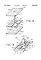
FIG. 12 is an exploded perspective view of another embodiment of the invention when employed as an accelerometer.
FIG. 13 is a perspective view of a third embodiment of the invention when used as a hybrid gyroscope and accelerometer.
FIG. 14 is a perspective view of a fourth embodiment of the invention when used as a vibratory sensor.
The invention and its various embodiments now having been visualized in the foregoing drawings, the preferred embodiments can be best understood by now turning to the following detailed description.
DETAILED DESCRIPTION OF THE PREFERRED EMBODIMENTS
The illustrated embodiment of the invention shall be described in terms of a microgyroscope, accelerometer and sensor, but it is to be understood that the principles and scope of the invention may be realized and implemented in any implementation consistent with the disclosed concepts and should not be limited to the following illustrations. Therefore, whereas the bulk of the illustrated embodiment shall be discussed in terms of a microgyroscope, it should always be kept in mind when reading the specification that the invention is to be more broadly construed and equally applicable to other types of applications.
Future spacecraft will require performance microgyroscopes that are compact and cost effective with low power consumption for attitude and maneuver control, tumble recovery, stabilization and pointing of instruments such as cameras, antennas, detectors and solar panels. Microgyroscopes with 0.1 to 10 degree per hour biased stability performance will also find application in inertial reference systems and in external inertial reference systems such as in the global positioning system (GPS), as sun sensors, or star trackers. For example, a sun sensor cannot be used during an eclipse, during periods of several minutes between star sightings within the narrow field of view star tracker, or when a GPS navigation signal suffers short term dropouts due to inadequate antenna coverage or physical electromagnetic interference. The disclosed microgyroscopes, therefore, will not only be useful for various extraterrestrial missions such as planetary or interplanetary astrophysical research, but also will have substantial terrestrial applications in automotive navigational systems, autonomous control of underwater and land vehicles, platform stabilization, a smart guidance for munitions, missiles and robotics. For example, the gyroscope of the invention can be used in a small handheld mobile navigation system in conjunction with and integrated with conventional GPS.
Recent attempts to implement vibratory microgyroscopes have faced several difficulties. To achieve resonance matching between the driven and sense modes requires extreme mechanical precision. To avoid electronic limitations due to parasitic capacitance, complex fabrication processes were also necessary. These prior vibratory microgyroscope designs typically have only a maximum mass value of approximately 10-10 kg, a minimum spring constant of approximately 1 N/m and resonant frequencies in the range of 20 to 30 KHz. The high resonant frequencies results in reduced signal outputs. The small mass leads to large damping and large Brownian noise. The small capacitance of the drive and sense structures limits the detection sensitivity. The design characteristics result in microgyroscopes that have drift rates that range from 30 to 5000 degrees per hour.
In the present invention the Q factor of microgyroscope 10 increases from about 10 at one atmosphere pressure to greater than 10,000 at less than one miliTorr. It is larger due to the low mechanical losses. The circuitry actively tracks frequency drifts in the drive resonance due to temperature changes and adjusts the drive frequency to always match the frequency of mechanical resonance. The circuit also actively detects and tracks the amplitude of the driven oscillation and actively corrects and maintains a constant drive amplitude.
The illustrated microgyroscope described below offers several technical features which include, but are not limited to:
(1) the use of simple bulk silicon technology which provides precise structures, increases yield, and reduces cost;
(2) high rotation rate sensitivity due to the low frequency resonator design, differential mode of operation, and lock in amplifier detection;
(3) a low loss resonator with a high Q factor for mechanical amplification;
(4) a symmetric resonator with frequency matched resonant modes and reduced temperature variation dependence;
(5) the gyroscope utilizes energy transfer between two degenerate modes to sense rotation rate; and
(6) symmetric damping for all the degenerate modes.
In vibratory gyroscopes in general, there is a rotation sensing mechanical element which is initially driven to oscillate in a first mode, typically termed an input or drive mode. Under rotation, Coriolis acceleration induces energy transfer from the input mode to a second oscillatory mode, typically termed an output or sense mode, which causes the sensing element to be excited. The best performance for a vibratory gyroscope is obtained when the oscillatory modes, the drive and sense modes, have the same resonant frequency and a high quality or Q factor. The response to the Coriolis acceleration is then mechanically amplified by the Q factor of the resonance and results in improved sensor performance.
A simplified perspective view of a portion of the microgyroscope of the invention is depicted in the perspective view of FIG. 1. The microgyroscope, generally denoted by reference numeral 10, in the illustrated embodiment is comprised of a 4-leaf clover, generally denoted by reference numeral 12, suspended by four wires or springs 14 extending between clover 12 and rim 16. In the preferred embodiment a two-fold symmetric clover leaf pattern with square leaves 22a-d is used, but any symmetric, planar pattern may be substituted if desired. For example, if desired six or eight leaf clover pattern could be used or even more complex symmetric patterns chosen if desired. For example, multiply lobed cluster patterns or grape clusters having two fold symmetry could also be utilized in the same manner as disclosed here for a four leaf clover pattern. A square, four-leaf pattern is preferred for ease of fabrication as will become apparent in connection with the following description. Rim 16, clover structure 12 and springs 14 are micromachined from a single crystal of silicon. In the preferred embodiment, a metal or brass post 18 is rigidly attached through a center 20 of clover structure 12 in a direction perpendicular to the plane of clover leaves 22a-d. Four silicon suspension springs 14 provide mechanical support and a restoring spring force for the oscillatory motion of microgyroscope 10. Clover leaf structure 12 and metal post 18 have a combined mass in the illustrated embodiment of about 10-5 kg. Microgyroscope 10 is shown as best measuring the rate of rotation about the inertial Z axis parallel to the post. Three of such microgyroscopes each oriented in a different orthogonal direction will thus provide three axis sense rotation.
The mechanical resonant frequency of the microgyroscope in the illustrated embodiment of FIGS. 1 and 2 varies according to its design in the range of 200 to 1000 Hz. The resonant frequency may be chosen at any frequency consistent with the teachings of the present invention. The low resonant frequency in the illustrated embodiment as compared to prior art vibratory gyroscopes is due to a large mass of post 18 and the softness of suspension springs 14. Since the Coriolis response of gyroscope 10 is inversely proportional to its resonant frequency, a low resonant frequency increases the device responsitivity.
Silicon clover leaf structure 10 with post 18 is bonded to a quartz base plate 24, as best depicted in the exploded perspective view of FIG. 2. Quartz base plate 24 is patterned with Cr/Au electrodes 26a and b. The large planar overlap of clover leaves 22a-d to electrodes 26a and b provides large areas for electrostatic driving and capacitive sensing. Each of electrodes 26a and b are coupled through metalizations (not shown) leading to silicon electronics as shown in FIG. 3. In the preferred embodiment gyroscope 10 and its associated electronics are integrally fabricated by using conventional silicon integrated circuit processing technology. The resonator combination of electrodes 26a and b and clover leaves 22a-d is excited by applying an AC voltage from an automatic gain control amplifier 28, symbolically representing the transfer function of all the electronics, to electrodes 26a, which are associated with leaves 22b and c. This excites a rotation of leaves 22b and c around the X-axis 30 as depicted in FIG. 1. Since the resonator of gyroscope 10 is symmetric, that is each of the elements comprising any part of the oscillating elements within gyroscope 10 has mirror symmetry about both the X and Y axes, the resonance modes about the X axis 30 and Y axis 32 are matched in frequency with a rocking-like displacement of clover leaves 22a-d. The rocking of leaves 22a and 22d is sensed capacitively through electrodes 26b and are coupled to differential amplifier 34 shown in FIG. 3. The degeneracy of the drive and sense modes in gyroscope 10 allows Q factor amplification of the modal displacements.
The Q factor amplification of the drive and sense motion also reduces the drive voltage needed from agc amplifier 28 and increases the sensitivity of output provided to the differential amplifier 34. The Q factor of this symmetric resonator structure can be very high, since the structure can be perfectly balanced as described below with a fixed center of gravity largely defined by the placement of metal post 18 with its center of gravity at or very near the geometric center of the plane of clover leafs structure 12. The linear forces and moments resulting from vibration modes thus can be zero or very near zero.
Since post 18 is rigidly attached to clover leaf structure 12, the movement of clover leaves 22a-d translates into movement of post 18, which can be viewed conceptually as a double pendulum. When leaves 22a and d oscillate in the drive mode, the displacement of post 18 is nearly parallel to the Y-axis 32 direction. As an external rotation is applied in the direction of Z axis 36, a Coriolis force acts on oscillating post 18 causing it to be displaced in the orthogonal direction, namely in this illustration initially in the X direction 30. For a rigid post and leaf structure combination the post displacement is translated back into a rocking motion about Y axis 32 of clover leaves 22a-d. Post 18 thus provides a large Coriolis coupling which transfers energy between the two orthogonal rocking modes about X axis 32 aligned with springs 14 extending between clover leaves 22a and b on one hand and clover leaves 22c and d on the other, and springs 14 aligned with X axis 30 extending between clover leaves 22a and d on one hand and clover leaves 22b and c on the other.
Before considering further aspects of the control and signal read out, consider first the fabrication of gyroscope 10. The structure of silicon microgyroscope 10 shown in FIG. 2 can be characterized as a quartz based plate 24 patterned with metal electrodes 26a and b and a silicon clover leaf resonating structure 12 suspended inside a silicon rim 16. Quartz base plate 24 and silicon rim 16 can be bonded together by several methods, for example by using low shrinkage ultraviolet curable epoxy or other methods of equivalent bonding such as by conductive epoxy or wafer bonding. In the illustrated embodiment the overall dimension of mechanical resonator 12 is 7×7 mm and the dimension of each clover leaf 22a-d is about 1.1 mm by 1.1 mm. Post 18 is 500 microns in diameter and 5 mm in length. Quartz base plate 24 is a square 1 cm by 1 cm and approximately 400 microns thick. The sensing capacitors of microgyroscope 10 are formed between the chromium/gold electrodes 26b on quartz base plate 24 and silicon clover leaves 22a and d. The gap between base electrodes 26b and clover leaves 22a and d is typically in the range of 10 to 20 microns.
The fabrication of the silicon clover leaf resonating structure requires only two etching and masking steps using bulk micromachining technology. As best illustrated FIGS. 4a-d, which are a simplified cross-sectional diagrams of the fabrication process, the fabrication methodology begins with a standard n-type or phosphorous or arsenic doped, <100>, double-sided polished silicon wafer 38 that has two epitaxial silicon layers 40 and 42 disposed thereon. The first epitaxial layer 40 is a p+ etch-stop layer, which in the illustrated embodiment is a 1020 boron doped layer. Upper layer 42 is a 26 micron n-type silicon epilayer. A silicon dioxide layer 44 is thermally grown on the wafer and then patterned with the clover leaf pattern depicted in FIGS. 1 and 2. This patterned oxide layer 44 is used as a mask for EDP etching of silicon layer 42 down to etch-stop layer 40, resulting in the fabricated pattern as shown in the cross-sectional view of FIG. 4a. The longitudinal axis of spring 14 and their etched surfaces, the edges of clover leaves 22a-d, and all of the features of the resonator comprising the geometry of rim 16, clover leaves 22a-d and springs 14 are aligned with the crystallographic axis of wafer 38 so that their edge surfaces are extremely smooth and lie along defined crystalline planes. Therefore, very precise dimensions and shapes for springs 14 as well as each of the other edges are provided by the anisotropic EDP etch. This not only provides a very precisely symmetric resonating structure, but provides symmetric mechanical parameters for springs 14 which are material to establishing the degenerate modal responses and resonant frequencies of microgyroscope 10. One of the most difficult problems in the prior art was to provide designs which could avoid any kind of asymmetry, which strongly effects the modal frequencies and prevent degeneracy in the drive and sensed resonances.
Thermal oxide mask 44 is stripped off with a wet, buffered hydrofluoric etch and is then followed by 300 angstrom thick thermal silicon dioxide layer 46 resulting in the structure of FIG. 4b. Silicon dioxide layer 46 on the back of microgyroscope 10 is patterned as shown in FIG. 4b and then etched to remove almost all of the silicon substrate 36 down to etch-stop layer 40 as shown in the resulting structure in FIG. 4c. Next, wafer 38 is cleaved into individual devices and separated. The cleaved devices are then etched in hydrofluoric acid until stop-etch layer 40 is removed resulting in the structure as shown in FIG. 4d. Removal of both etch-stop layer 40 and silicon dioxide layers 46 removes any stress gradients which might otherwise tend to cause warpage of the suspended clover leaf structure 22a-d and hence loss of symmetry.
The fabrication process for quartz based plate 24 is depicted in FIGS. 5a and b, which again show the fabrication steps in side cross-sectional view. Quartz plate 48 is first drilled to define a bore 50 for post 18. Plate 48 is then patterned and etched to a depth of approximately 10 to 20 microns using hydrofluoric acid to define a well 52. Well 52 provides a spacing gap that separates silicon clover leaves 22a-d and electrodes 26a and b on quartz base plate 24. Next a chromium/gold metalization is evaporated onto quartz plate 48 as shown in FIG. 5b to define electrodes 26a and b. Quartz plate 48 is then diced into individual devices to define individual device quartz base plates 24 and are bonded to the silicon resonator structure described in connection with FIGS. 4a-d using a UV curable epoxy or conductive epoxy or any other bonding methods. The devices are tested for resonant frequency and mode shapes. After the initial test, metal post 18 is then epoxied into a central bore 54 as shown in FIG. 2 defined in clover leaf resonator 22a-d.
The structure of the device now having been described in connection with FIGS. 1 and 2 and its fabrication in connection with FIGS. 4a-d and 5a and b, consider in further detail the electronics shown in FIG. 3 of actuating and sensing microgyroscope 10. For the purposes of visualization, an electrical model of gyroscope 10 is depicted in FIG. 6 into which the more significant parasitic effects are inserted such as interplate capacitances and the mechanical coupling between the orthogonal modes under no rotation. FIG. 6 shows a basic electrical model which gives the excitation-to-sense transfer function V2 /V1 or V3 /V4, of microgyroscope 10 taking each pair of opposite plates at a time, wherein the voltages V1 -V4 correspond to the angular displacements of clover leaves 22a-d respectively. The mechanical resonance of silicon clover leaf resonator 22a-d is modeled by series resonant circuit 58 comprised of LμCμRμ which is excited by dependent voltage sources 64 and 66 denoted as δV1 and δV2 respectively, which communicate with port voltages 60 and 62, denoted at V1 and V2 respectively. The δ representation signifies the deflection per volt in plates 22a-d at zero frequency.
The effective mechanical motion on electrical ports 60 and 62 in turn is given by dependent sources 68 and 70, denoted as a.sub.μ i.sub.μ. The interplate parasitic resistance and capacitance is modeled by parallel RC circuit 72, Rp and Cp. Dependent source 74, δ.sub.ω Vcμ is the Coriolis induced term described below. The transfer function predicted by the model of FIG. 6 with ω=0 and hence δ.sub.ω =0 is depicted in FIG. 7 in which is notch 76 at ω=ωn is mainly due to parasitic capacitance 72, Cp. FIG. 7 shows a transfer functions V2 /V1 or V3 /V4 in the vertical axis in a logarithmic scale with frequency graphed along the horizontal access. An actual experimental transfer function as measured is shown in FIG. 8 of each pair of opposite plates of microgyroscope 10 with drive and sense resonant modes at 445 Hz and 435 Hz respectively. The departure of each of these transfer functions from the predicted function of FIG. 7 for a pair of single plates is primarily caused by parasitic electrical and mechanical coupling between the two orthogonal modes when gyroscope 10 is at rest and by a slight difference between the δ and α.sub.μ for each pair of plates.
The model of FIG. 6 is a model for only a single pair of plates. The complete electrical model for gyroscope 10 is shown in FIG. 9, where the subscripts 1-4 refer respectively to the performance parameters of clover leaves 22a-d respectively in analogy with the same designations discussed above in connection with FIG. 6. The transfer functions for the model of FIG. 9 again are depicted in FIG. 10 and correspond substantially to those measured in FIG. 8.
The actuation or drive circuitry is realized by designing agc amplifier 28 so that it locks into the drive resonance mode. The driving voltage of microgyroscope 10 from agc amplifier 28 varies from approximately 0.5 to 10 volts peak to peak depending on the device design and Q factor with the snap down voltage at approximately 20 volts, i.e. the voltage necessary to retain clover leaves 22a-d in a down position against the restorative force of springs 14. The diagram of FIG. 3 shows clover leaves 22a-d exposed above and covering underlying electrodes 26a and b so that is should be understood that the conductive lines shown in the circuitry of FIG. 3 are not directly electrically coupled to clover leaves 22a-d, but to their underlying electrodes. The diagram of FIG. 3 symbolically places clover leaves 22a-d over and obscures electrodes 26a and b for the purposes of ease of visualization of the drive provided through electrodes 26a and b to clover leaves 22a-d. As shown, the signals from electrodes 26b, the sensing electrodes, are both differenced in differential amplifier 34 and summed in summing amplifier 78. The purpose of summing sense signals from electrodes 26b is to remove the difference signal between them and hence the response of the sensed resonance from the feedback loop. The output of summing circuit 78 is fed back to agc amplifier 28 to provide a feedback signal to agc amplifier 28 independent of the sensed response. The sense circuit, differential amplifier 34, on the other hand, subtracts the sensed signals from electrodes 26b in order to remove the common mode drive signal. A lock-in amplifier 80 is used to detect the differential signal caused by the rotation of gyroscope 10 about the z axis. The output of agc amplifier 28 is also provided as the reference signal to lock in amplifier 80.
By way of example, in tests of an initially fabricated microgyroscope 10, the resonant frequency of the drive mode has been measured at 452 Hz and the sense mode at 447 Hz with Q factors for both modes at approximately 500. The resonant modes are rocking modes of modal lines along the spring directions, i.e. the longitudinal directions of springs 14. The separation between the resonant frequencies in the sense and drive modes was primarily due to stress from the bonding of silicon clover leaf structure 22a-d and rim 16 to quartz base plate 24 and to small fabrication errors. By improved bonding technique and fabrication, the frequency split between the sense and drive modes has been substantially narrowed in later fabricated microgyroscopes and has resulted in significant Q factor amplification of the sense mode displacement.
The output voltage, Vout, for the initially fabricated microgyroscope and circuitry of FIG. 3, is graphed against rotation rate measured in degrees per hour as depicted in FIG. 11. The measured responsitivity or scale factor of gyroscope 10 is linear and was measured at 10.4 millivolts per degree per second with a nonlinearity of at less than 1% at an integration time of one second. Closed circuitry may be employed to improve the sensitivity of microgyroscope 10 by lowering noise and reducing drift.
Theoretically, the microgyroscope of the invention is capable of detecting rotation rates of less than one degree per hour with rotation rates of 90 degrees per hour currently being realized. While the illustrated embodiment shows resonant frequencies between 400 and 500 Hz, it is anticipated that resonant frequencies between approximate 0.1 to 10 kHz can be realized by design selection. Because of the increased sensitivity of the design it may also be driven off resonance thereby eliminating the need for mechanical matching between the sensed and driven modes.
Although the preferred embodiment utilizes normal modes around the X and Y axis, it is also within the scope of the invention that modes along the axis displaced 45° from the X and Y axis may also be utilized. In this case, clover leaves 22a-d would be paired as leaves 22a and c on one hand and 22b and d on the other. A modification of the microgyroscope 10 as diagrammatically depicted in FIG. 12 provides for a three axis accelerometer denoted generally by reference numeral 82. The elements of accelerometer 82 are identical with those of gyroscope 10 with the exception that post 18, which has its mass symmetrically disposed with respect to clover leaves 22a-d in the embodiment of FIGS. 1-11, is provided as an asymmetric post, or more specifically a half post 84 in the illustration of FIG. 12. Post 84 is also shown as a square pest as opposed to a rod. The cross-sectional configuration of post 84 is largely a matter of design choice and fabrication convenience. Each of the elements in FIG. 12 coact substantially as indicated above with the exception that a second identical base plate 24' is shown in the exploded perspective view of FIG. 12.
Consider the operation of the embodiment of FIG. 12. For example, initially, all four clover leaves 22a-d and post 84 are driven to oscillate in a Z direction. Under an input acceleration in the positive X direction, post 84 tilts toward the negative X direction. Thus the motion of post 84 is a superposition of oscillatory Z motion and negative X motion. Since post 84 is rigidly attached to clover leaves 22a-d, the leaves also experience the same motions. The motion of leaves 22a-d thus produce an oscillating asymmetric capacitance between clover leaves 22a-d and corresponding base electrodes in base plates 24 and 24'. The asymmetry of the capacitance is detected using a lock-in amplifiers described above in connection with FIG. 3 locked onto the resonant frequency of the Z oscillation. By this means the signal-to-noise ratio the signal is increased as is the sensitivity of the accelerometer 82. The measure of the asymmetry of the oscillating capacitance between the electrodes is directly related to the linear acceleration. Since accelerometer 82 is symmetrical in the X-Y plane, it is capable of sensing both accelerations in the X and Y direction. Acceleration in the Z direction can also be detected by monitoring capacitances associated with each of the four clover leaves 22a-d. Under accelerations in the Z direction, all four clover leaves 22a-d will move up or down depending on the direction of acceleration superimposed upon the drive oscillation. This additional Z-movement of clover leaves 22a-d is capacitively detected between the clover leaves and base electrodes in base plates 24, 24'. Thus, by monitoring capacitance changes of all four clover leaves 22a-d, acceleration in all three directions can be determined. Accelerations in the nano g range are realized by appropriate design selections of operating parameters.
It is further within the scope of the invention that the accelerometer FIG. 12 may be combined with a microgyroscope of FIGS. 1-11. As seen in the diagrammatic depiction of FIG. 13 a hybrid device, generally denoted by reference numeral 86, having essentially the same elements as FIGS. 1-12, is provided wherein post 18 and 84 is replaced by an asymmetric post 88. An illustrated embodiment post 88 is shaped as cylindrical rod in its lower portion 90, while it has a conical shape on its upper portion 92. The asymmetric distribution of mass within rod 88 thus combines the gyroscopic response of the embodiment of FIGS. 1-11 with the accelerometer response of FIG. 12. In this case the drive mechanism also becomes a superposition of Z oscillation of accelerometer 82 combined with the rotational drive of the gyroscope of FIGS. 1 and 2. The operational responses are then decoded or separated from each other in the output circuitry which includes algorithmically controlled data signal processing for this purpose.
Alternatively, it may be possible to multiplex between rotational and translational oscillatory drive modes in an appropriately damped system, which may contemplate the operation of hybrid device 86 within a fluidic environment as opposed to an gas, air or partial vacuum environment contemplated for the device of FIGS. 1-12.
FIG. 14 is a perspective view of another embodiment of the invention wherein clover leaves 22a-d are utilized together with rim 16 and springs 14 in combination with an electrode base substrate 24 in the absence of any central mass or bar 18, 84 or 88. This embodiment device is used as a resonator, generally denoted by reference numeral 94, in substantially the same manner as described in connection with gyroscope 10 in FIGS. 1-11. The Q factor of resonator 94 is expected to exceed 50,000 when driven at its resonant frequency. Each of the advantages utilized in microgyroscope 10 arising from the symmetry of springs 14, clover leaves 22a-d and rim 16 are also realized in resonator 94 of FIG. 14. This includes frequency matching of resonant frequencies for both input and output vibrational modes and differential temperature dependence between the two oscillatory modes. The high Q factor could thus be utilized in any type of transducer of physical phenomena for producing an output signal.
Many alterations and modifications may be made by those having ordinary skill in the art without departing from the spirit and scope of the invention. Therefore, it must be understood that the illustrated embodiment has been set forth only for the purposes of example and that it should not be taken as limiting the invention as defined by the following claims.
For example, although the illustrated embodiment has been described as micromachined from silicon with a quartz base plate and brass post, the entire the device could be made from silicon, metal, plastic, ceramic, any other crystalline or noncrystalline material or combinations of the same. For example, the quartz base plate and post are currently contemplated as being replaced by a silicon ones or versions made from plastic, ceramic, any other crystalline or noncrystalline material.
Further, although micromaching is the preferred mode of manufacturing, manufacturing of the element by mold injection or any other means now known or later devised is equivalent.
While the resonant modes in the illustrated invention are described as being aligned with the spring axes, it is also clear that modal oscillations can be established along nonaligned axes as well.
Still further, while the invention has largely been illustrated in terms of a gyroscope, its application in an accelerometer has also be briefly described. It could also be included in a vibration sensor, a seismometer, a pressure sensor, an actuator for the displacement of fluids, gases and particles, an optical beam deflector, steerer and mirror, a resonator reference or oscillator, and an oscillator for use in electromechanical apparatus. The invention can be employed in each of the above applications with oscillation. The leaf structure is oscillated primarily to enhance the signal-to-noise ratios by the use of lock-in detection, and secondarily to operate as a vibratory gyroscope. In nongyroscopic applications or applications where lower signal-to-noise ratios can be tolerated, oscillation of the leaf structure is not required.
The words used in this specification to describe the invention and its various embodiments are to be understood not only in the sense of their commonly defined meanings, but to include by special definition in this specification structure, material or acts beyond the scope of the commonly defined meanings. Thus if an element can be understood in the context of this specification as including more than one meaning, then its use in a claim must be understood as being generic to all possible meanings supported by the specification and by the word itself.
The definitions of the words or elements of the following claims are, therefore, defined in this specification to include not only the combination of elements which are literally set forth, but all equivalent structure, material or acts for performing substantially the same function in substantially the same way to obtain substantially the same result.
Insubstantial changes from the claimed subject matter as viewed by a person with ordinary skill in the art, now known or later devised, are expressly contemplated as being equivalently within the scope of the claims. Therefore, obvious substitutions now or later known to one with ordinary skill in the art are defined to be within the scope of the defined elements.
The claims are thus to be understood to include what is specifically illustrated and described above, what is conceptionally equivalent, what can be obviously substituted and also what essentially incorporates the essential idea of the invention.

Claims (34)

We claim:
1. A micromachined resonator comprising:
a micromachined symmetric leaf structure having a plurality of symmetrically disposed leaves about a defined center;
at least one micromachined spring symmetrically disposed with respect to said symmetric leaf structure and supporting said symmetrical leaf structure;
a rim/base structure to which said spring is coupled, said rim/base structure including a plurality of sensing and drive electrodes; and
a circuit electrically coupled to said electrodes included within said rim/base structure, said circuit for providing drive signals to said drive electrodes to oscillate said symmetric leaf structure and to receive a sensing signal from said sensing electrodes to detect response of said oscillating symmetric leaf structure to physical phenomena exterior to said micromachined resonator,
whereby a rugged, small, low cost, high performance vibratory sensor is provided.
2. The resonator of claim 1 wherein a plurality of said springs are provided for coupling and supporting said symmetric leaf structure to said rim/base structure.
3. The resonator of claim 2 wherein said plurality of springs are symmetrically disposed with respect to said symmetric leaf structure.
4. The resonator of claim 3 wherein said symmetric leaf structure and plurality of springs are symmetric about at least two separate axes.
5. The resonator of claim 4 wherein one of said two separate axes of symmetry of said symmetric leaf structure and a plane in which said plurality of springs lie are orthogonal to each other.
6. The resonator of claim 5 further comprising a mass element coupled to said symmetric leaf structure.
7. The resonator of claim 6 wherein said mass element is symmetrically disposed to said symmetric leaf structure.
8. The resonator of claim 7 wherein said symmetric leaf structure is substantially defined in a plane and said mass element extends in a direction substantially perpendicular to said plane of said symmetric leaf structure.
9. The resonator of claim 8 wherein said mass element is a cylinder disposed through a center of mass of said symmetric leaf structure.
10. The resonator of claim 6 wherein said circuit drives said drive electrodes and senses said sensing electrodes to operate said resonator as a microgyroscope.
11. The resonator of claim 1 wherein said symmetric leaf structure is a clover leaf pattern comprised of four leaves symmetrically disposed about said center and wherein said clover leaf pattern is disposed within a plane.
12. The resonator of claim 11 further comprising four springs connected to said clover leaf pattern and symmetrically disposed between each of said four clover leaves to connect said center with said rim/base and to support said clover leaf pattern relative to said rim/base structure.
13. The resonator of claim 12 wherein said rim/base structure comprises a rim disposed in said plane of said clover leaf pattern and a base disposed beneath said rim and coupled to said rim.
14. The resonator of claim 13 wherein said electrodes provided within said rim/base structure are provided on said base, two electrodes being provided as said drive electrodes and two electrodes being provided as said sensing electrodes, said driving and sensing electrodes positioned on said base opposite corresponding ones of said leaves in said clover leaf pattern, each of said driving and sensing electrodes being positioned opposite a different one of said leaves.
15. The resonator of claim 13 wherein said rim is symmetric with said clover leaf pattern and said springs.
16. The resonator of claim 1 wherein said circuit differentially senses said sensing signal from said sensing electrodes to reject common mode signals from said sensing electrodes.
17. The resonator of claim 1 wherein said symmetric leaf structure has at least two resonant modes and wherein symmetry of said symmetric leaf structure causes two resonant modes to be degenerate.
18. The resonator of claim 1 wherein said leaves of said symmetric leaf structure and said sensing and drive electrodes of said rim/base structure define large coplanar opposing surfaces from each other for increased drive and sensing.
19. A method of operating a vibratory micromachined resonator comprising the steps of:
oscillating a micromachined symmetric leaf structure having a plurality of symmetrically disposed leaves about a defined center, said symmetric leaf structure including at least one micromachined spring symmetrically disposed with respect to said symmetric leaf structure and supporting said symmetrical leaf structure for providing a restoring force to said symmetric leaf structure; and
sensing Coriolis perturbations caused in said oscillating symmetric leaf structure;
whereby motion is detected in a rugged, small, low cost, high performance vibratory sensor.
20. The method of claim 19 where said step of sensing Coriolis perturbations is capacitively performed between said symmetric leaf structure and a plurality of sensing and drive electrodes disposed in a rim/base structure to which said spring is coupled.
21. The method of claim 20 where said step of sensing is performed by a circuit electrically coupled to said electrodes included within said rim/base structure, said circuit providing drive signals to said drive electrodes to oscillate said symmetric leaf structure and to receive a sensing signal from said sensing electrodes to detect response of said oscillating symmetric leaf structure to physical phenomena exterior to said micromachined resonator.
22. The method of claim 19 where said step of oscillating said symmetric leaf structure oscillates said symmetric leaf structure in one or more plurality of modes about a plurality of said springs supporting said symmetric leaf structure with respect to said rim/base structure.
23. The method of claim 22 where said step of oscillating said symmetric leaf structure oscillates said symmetric leaf structure about said plurality of springs, which are symmetrically disposed with respect to said symmetric leaf structure.
24. The method of claim 23 where said step of oscillating said symmetric leaf structure about said plurality of symmetric springs oscillates said symmetric leaf structure in at least two separate modes.
25. The method of claim 24 where said step of oscillating said symmetric leaf structure about said plurality of symmetric springs oscillates said symmetric leaf structure about at least two separate axes.
26. The method of claim 19 further comprising the step of oscillating a mass element rigidly connected to said symmetric leaf structure.
27. The method of claim 26 where said step of oscillating a mass element comprises the step of oscillating a mass element symmetrically disposed with respect to said symmetric leaf structure.
28. The method of claim 27 where said step of oscillating a mass element comprises the step of oscillating a cylinder disposed through a center of mass of said symmetric leaf structure and extending at least in part perpendicular to said symmetric leaf structure.
29. A sensor comprising:
a symmetric leaf structure having a plurality of symmetrically disposed leaves about a defined center;
at least one spring symmetrically disposed with respect to said symmetric leaf structure and supporting said symmetrical leaf structure;
a rim/base structure to which said spring is coupled, said rim/base structure including a plurality of sensing electrodes; and
a circuit electrically coupled to said electrodes included within said rim/base structure, said circuit for receiving a sensing signal from said sensing electrodes to detect response of said symmetric leaf structure to physical phenomena exterior to said sensor,
whereby a rugged, small, low cost, high performance sensor is provided.
30. The sensor of claim 29 wherein said symmetric leaf structure is a clover leaf pattern comprised of four leaves symmetrically disposed about said center and wherein said clover leaf pattern is disposed within a plane.
31. The resonator of claim 30 further comprising four springs connected to said clover leaf pattern and symmetrically disposed between each of said four clover leaves to connect said center with said rim/base and to support said clover leaf pattern relative to said rim/base structure.
32. The resonator of claim 31 wherein said rim/base structure comprises a rim disposed in said plane of said clover leaf pattern and a base disposed beneath said rim and coupled to said rim.
33. The resonator of claim 32 wherein said electrodes provided within said rim/base structure are provided on said base, said electrodes being provided as said sensing electrodes, said sensing electrodes positioned on said base opposite corresponding ones of said leaves in said clover leaf pattern, each of said sensing electrodes being positioned opposite a different one of said leaves.
34. The resonator of claim 32 wherein said rim is symmetric with said clover leaf pattern and said springs.
US08/657,685 1996-05-31 1996-05-31 Silicon bulk micromachined, symmetric, degenerate vibratorygyroscope, accelerometer and sensor and method for using the same Expired - Fee Related US5894090A (en)

Priority Applications (5)

Application Number Priority Date Filing Date Title
US08/657,685 US5894090A (en) 1996-05-31 1996-05-31 Silicon bulk micromachined, symmetric, degenerate vibratorygyroscope, accelerometer and sensor and method for using the same
AU32880/97A AU3288097A (en) 1996-05-31 1997-05-30 Silicon macromachined symmetric vibratory gyroscope sensor
PCT/US1997/009021 WO1997045702A1 (en) 1996-05-31 1997-05-30 Silicon macromachined symmetric vibratory gyroscope sensor
DE69731742T DE69731742T2 (en) 1996-05-31 1997-05-30 SYMMETRIC VIBRATION CIRCULAR SENSOR MADE FROM SILICON IN MICROTECHNOLOGY
EP97928679A EP0902875B1 (en) 1996-05-31 1997-05-30 Silicon macromachined symmetric vibratory gyroscope sensor

Applications Claiming Priority (1)

Application Number Priority Date Filing Date Title
US08/657,685 US5894090A (en) 1996-05-31 1996-05-31 Silicon bulk micromachined, symmetric, degenerate vibratorygyroscope, accelerometer and sensor and method for using the same

Publications (1)

Publication Number Publication Date
US5894090A true US5894090A (en) 1999-04-13

Family

ID=24638237

Family Applications (1)

Application Number Title Priority Date Filing Date
US08/657,685 Expired - Fee Related US5894090A (en) 1996-05-31 1996-05-31 Silicon bulk micromachined, symmetric, degenerate vibratorygyroscope, accelerometer and sensor and method for using the same

Country Status (5)

Country Link
US (1) US5894090A (en)
EP (1) EP0902875B1 (en)
AU (1) AU3288097A (en)
DE (1) DE69731742T2 (en)
WO (1) WO1997045702A1 (en)

Cited By (101)

* Cited by examiner, † Cited by third party
Publication number Priority date Publication date Assignee Title
US6044708A (en) * 1998-03-04 2000-04-04 Alps Electric Co., Ltd. Oscillation type gyroscope
US6079282A (en) * 1998-06-26 2000-06-27 Bossard Technologies Ag Capacitive force sensor
US6079272A (en) * 1997-08-13 2000-06-27 California Institute Of Technology Gyroscopes and compensation
US6117701A (en) * 1996-08-09 2000-09-12 Robert Bosch Gmbh Method for manufacturing a rate-of-rotation sensor
US6164134A (en) * 1999-01-29 2000-12-26 Hughes Electronics Corporation Balanced vibratory gyroscope and amplitude control for same
WO2001001153A1 (en) * 1999-06-29 2001-01-04 California Institute Of Technology Z-axis vibratory gyroscope
US6289733B1 (en) * 1999-05-12 2001-09-18 Hughes Electronics Corporation Planar vibratory gyroscopes
US6308567B1 (en) * 1998-12-10 2001-10-30 Denso Corporation Angular velocity sensor
WO2002010684A2 (en) * 2000-08-01 2002-02-07 Hrl Laboratories, Llc Three-axes sensor and a method of making same
US6367786B1 (en) 1999-06-07 2002-04-09 California Institute Of Technology Micromachined double resonator
US6418789B1 (en) * 1999-02-26 2002-07-16 Murata Manufacturing Co., Ltd. Vibrating gyroscope
US6487907B1 (en) * 1999-07-08 2002-12-03 California Institute Of Technology Microgyroscope with integrated vibratory element
US6513380B2 (en) * 2001-06-19 2003-02-04 Microsensors, Inc. MEMS sensor with single central anchor and motion-limiting connection geometry
WO2003023414A1 (en) * 2001-09-04 2003-03-20 Tokyo Electron Limited Microstructure with movable mass
WO2003025500A2 (en) * 2001-08-17 2003-03-27 The Boeing Company Microgyroscope with electronic alignment and tuning
US20030057447A1 (en) * 2001-09-26 2003-03-27 Hitachi Metals, Ltd. Acceleration sensor
US6555404B1 (en) 2000-08-01 2003-04-29 Hrl Laboratories, Llc Method of manufacturing a dual wafer tunneling gyroscope
US6563184B1 (en) 2000-08-01 2003-05-13 Hrl Laboratories, Llc Single crystal tunneling sensor or switch with silicon beam structure and a method of making same
US20030101792A1 (en) * 2001-08-10 2003-06-05 Kubena Randall L. Microgyro tuning using focused ion beams
US6580138B1 (en) 2000-08-01 2003-06-17 Hrl Laboratories, Llc Single crystal, dual wafer, tunneling sensor or switch with silicon on insulator substrate and a method of making same
US6582985B2 (en) 2000-12-27 2003-06-24 Honeywell International Inc. SOI/glass process for forming thin silicon micromachined structures
US6584845B1 (en) 1999-02-10 2003-07-01 California Institute Of Technology Inertial sensor and method of use
US6629460B2 (en) 2001-08-10 2003-10-07 The Boeing Company Isolated resonator gyroscope
US6630367B1 (en) 2000-08-01 2003-10-07 Hrl Laboratories, Llc Single crystal dual wafer, tunneling sensor and a method of making same
US6636819B1 (en) * 1999-10-05 2003-10-21 L-3 Communications Corporation Method for improving the performance of micromachined devices
US20030205087A1 (en) * 2001-08-10 2003-11-06 The Boeing Company Isolated resonator gyroscope with compact flexures
US20030209076A1 (en) * 2000-10-16 2003-11-13 Institute Of Microelectronics Z-axis accelerometer
US6672161B2 (en) * 2000-07-21 2004-01-06 Denso Corporation Semiconductor dynamic quantity sensor
US20040017620A1 (en) * 2002-07-24 2004-01-29 Shinji Kaneko Optical unit provided with an actuator
US20040055380A1 (en) * 2002-08-12 2004-03-25 Shcheglov Kirill V. Isolated planar gyroscope with internal radial sensing and actuation
US20040055381A1 (en) * 2002-08-12 2004-03-25 Shcheglov Kirill V. Integral resonator gyroscope
US20040088127A1 (en) * 2002-06-25 2004-05-06 The Regents Of The University Of California Integrated low power digital gyro control electronics
US20040085159A1 (en) * 2002-11-01 2004-05-06 Kubena Randall L. Micro electrical mechanical system (MEMS) tuning using focused ion beams
US20040168134A1 (en) * 2003-02-21 2004-08-26 Infineon Technologies North America Corp. Clock gating approach to accommodate infrequent additional processing latencies
US6808956B2 (en) 2000-12-27 2004-10-26 Honeywell International Inc. Thin micromachined structures
US20040226370A1 (en) * 2002-04-26 2004-11-18 California Institute Of Technology Electrostatic spring softening in redundant degree of freedom resonators
US20040237626A1 (en) * 2001-08-09 2004-12-02 Challoner A. Dorian Cloverleaf microgyroscope with electrostatic alignment and tuning
US20050017329A1 (en) * 2003-06-10 2005-01-27 California Institute Of Technology Multiple internal seal ring micro-electro-mechanical system vacuum package
US6876124B1 (en) * 2001-12-06 2005-04-05 Tera Fiberoptics Method and system for securing and controlling an electro-statically driven micro-mirror
US20050172714A1 (en) * 2002-08-12 2005-08-11 California Institute Of Technology Isolated planar mesogyroscope
US20050284222A1 (en) * 2004-06-29 2005-12-29 Johnson Burgess R MEMS gyroscope with horizontally oriented drive electrodes
US6990863B2 (en) 2001-08-10 2006-01-31 The Boeing Company Isolated resonator gyroscope with isolation trimming using a secondary element
US20060037417A1 (en) * 2004-07-29 2006-02-23 The Boeing Company Parametrically disciplined operation of a vibratory gyroscope
US7015060B1 (en) 2004-12-08 2006-03-21 Hrl Laboratories, Llc Cloverleaf microgyroscope with through-wafer interconnects and method of manufacturing a cloverleaf microgyroscope with through-wafer interconnects
US7017410B2 (en) 2001-08-10 2006-03-28 The Boeing Company Isolated resonator gyroscope with a drive and sense plate
JP2006105798A (en) * 2004-10-06 2006-04-20 Oki Electric Ind Co Ltd Semiconductor acceleration sensor and method for manufacturing same
US20070017287A1 (en) * 2005-07-20 2007-01-25 The Boeing Company Disc resonator gyroscopes
US7202100B1 (en) 2004-09-03 2007-04-10 Hrl Laboratories, Llc Method of manufacturing a cloverleaf microgyroscope and cloverleaf microgyroscope
US7232700B1 (en) 2004-12-08 2007-06-19 Hrl Laboratories, Llc Integrated all-Si capacitive microgyro with vertical differential sense and control and process for preparing an integrated all-Si capacitive microgyro with vertical differential sense
US20070180909A1 (en) * 2006-02-07 2007-08-09 Takeshi Uchiyama Angular velocity sensor
EP2028440A2 (en) 2007-07-31 2009-02-25 The Boeing Company Disc resonator integral inertial measurement unit.
US20090165558A1 (en) * 2007-12-28 2009-07-02 Schultz Peter S Caddie-corner single proof mass xyz mems transducer
US7640803B1 (en) 2004-05-26 2010-01-05 Siimpel Corporation Micro-electromechanical system inertial sensor
US20100103777A1 (en) * 2008-10-23 2010-04-29 Hon Hai Precision Industry Co., Ltd. Seismograph system
US20100251817A1 (en) * 2009-04-01 2010-10-07 The Boeing Company Thermal mechanical isolator for vacuum packaging of a disc resonator gyroscope
EP2246662A2 (en) 2009-05-01 2010-11-03 The Board of Trustees of The Leland Stanford Junior University Gyroscope utilizing MEMS and optical sensing
US20100300202A1 (en) * 2009-06-01 2010-12-02 Joyce Richard J Gyroscope packaging assembly
US20110048130A1 (en) * 2008-03-03 2011-03-03 Ramot At Tel-Aviv University Ltd. Micro Scale Mechanical Rate Sensors
US20110296915A1 (en) * 2010-06-07 2011-12-08 Bin Yang Multi-axis capacitive accelerometer
US8138016B2 (en) 2006-08-09 2012-03-20 Hrl Laboratories, Llc Large area integration of quartz resonators with electronics
US8151640B1 (en) 2008-02-05 2012-04-10 Hrl Laboratories, Llc MEMS on-chip inertial navigation system with error correction
US20120101729A1 (en) * 2010-10-24 2012-04-26 Takamune Cho Method and system for detecting ground displacement
US8176607B1 (en) 2009-10-08 2012-05-15 Hrl Laboratories, Llc Method of fabricating quartz resonators
US8187902B2 (en) 2008-07-09 2012-05-29 The Charles Stark Draper Laboratory, Inc. High performance sensors and methods for forming the same
CN102507980A (en) * 2011-11-02 2012-06-20 重庆理工大学 Silicon micro two-dimension acceleration sensor based on self-resonant technology
CN102507982A (en) * 2011-11-02 2012-06-20 重庆理工大学 Silicon micro-resonance type two-dimensional acceleration transducer based on photo-thermal effect
US20120227495A1 (en) * 2010-03-31 2012-09-13 Honeywell International Inc. Methods for making a sensitive resonating beam accelerometer
US8327526B2 (en) 2009-05-27 2012-12-11 The Boeing Company Isolated active temperature regulator for vacuum packaging of a disc resonator gyroscope
US20130000405A1 (en) * 2010-03-23 2013-01-03 Vincent Ragot Method of angular measurement by means of a vibrating sensor to which modulated controls are applied
US8393212B2 (en) 2009-04-01 2013-03-12 The Boeing Company Environmentally robust disc resonator gyroscope
CN103250057A (en) * 2010-11-26 2013-08-14 意法半导体股份有限公司 Resonant biaxial accelerometer structure of the microelectromechanical type
US20130233077A1 (en) * 2012-03-08 2013-09-12 Industrial Technology Research Institute Electrostatic force generator and force measurement system and accelerometer having the same
US20140013845A1 (en) * 2012-07-13 2014-01-16 Robert E. Stewart Class ii coriolis vibratory rocking mode gyroscope with central fixed post
US8766745B1 (en) 2007-07-25 2014-07-01 Hrl Laboratories, Llc Quartz-based disk resonator gyro with ultra-thin conductive outer electrodes and method of making same
US8769802B1 (en) 2008-02-21 2014-07-08 Hrl Laboratories, Llc Method of fabrication an ultra-thin quartz resonator
US8782876B1 (en) 2008-11-10 2014-07-22 Hrl Laboratories, Llc Method of manufacturing MEMS based quartz hybrid filters
US8912711B1 (en) 2010-06-22 2014-12-16 Hrl Laboratories, Llc Thermal stress resistant resonator, and a method for fabricating same
US9041463B2 (en) 2011-12-16 2015-05-26 Analog Devices, Inc. Low noise amplifier for multiple channels
US9250074B1 (en) 2013-04-12 2016-02-02 Hrl Laboratories, Llc Resonator assembly comprising a silicon resonator and a quartz resonator
US9309106B2 (en) 2013-07-08 2016-04-12 Motion Engine Inc. 3D MEMS device and method of manufacturing
CN105606201A (en) * 2016-01-28 2016-05-25 中北大学 Compound MEMS bionic hydrophone
US20160202366A1 (en) * 2013-03-14 2016-07-14 Pgs Geophysical As Force feedback electrodes in mems accelerometer
US9599470B1 (en) 2013-09-11 2017-03-21 Hrl Laboratories, Llc Dielectric high Q MEMS shell gyroscope structure
US9605964B2 (en) 2014-01-03 2017-03-28 The Boeing Company Gyro quadrature stabalization with demodulation phase error nulling
JP2017203683A (en) * 2016-05-11 2017-11-16 内外ゴム株式会社 Capacitance type triaxial acceleration sensor
US9977097B1 (en) 2014-02-21 2018-05-22 Hrl Laboratories, Llc Micro-scale piezoelectric resonating magnetometer
US9991863B1 (en) 2014-04-08 2018-06-05 Hrl Laboratories, Llc Rounded and curved integrated tethers for quartz resonators
US10031191B1 (en) 2015-01-16 2018-07-24 Hrl Laboratories, Llc Piezoelectric magnetometer capable of sensing a magnetic field in multiple vectors
US10110198B1 (en) 2015-12-17 2018-10-23 Hrl Laboratories, Llc Integrated quartz MEMS tuning fork resonator/oscillator
US10175307B1 (en) 2016-01-15 2019-01-08 Hrl Laboratories, Llc FM demodulation system for quartz MEMS magnetometer
US10214414B2 (en) 2014-01-09 2019-02-26 Motion Engine, Inc. Integrated MEMS system
US10266398B1 (en) 2007-07-25 2019-04-23 Hrl Laboratories, Llc ALD metal coatings for high Q MEMS structures
US10273147B2 (en) 2013-07-08 2019-04-30 Motion Engine Inc. MEMS components and method of wafer-level manufacturing thereof
US10308505B1 (en) 2014-08-11 2019-06-04 Hrl Laboratories, Llc Method and apparatus for the monolithic encapsulation of a micro-scale inertial navigation sensor suite
US10407299B2 (en) 2015-01-15 2019-09-10 Motion Engine Inc. 3D MEMS device with hermetic cavity
US10768065B2 (en) 2014-04-10 2020-09-08 Mei Micro, Inc. MEMS pressure sensor
CN111766405A (en) * 2020-05-14 2020-10-13 东南大学 Double-shaft silicon micro-accelerometer based on resonator energy localization effect
US11237000B1 (en) 2018-05-09 2022-02-01 Hrl Laboratories, Llc Disk resonator gyroscope with out-of-plane electrodes
US11287486B2 (en) 2014-12-09 2022-03-29 Motion Engine, Inc. 3D MEMS magnetometer and associated methods
US11674803B2 (en) 2014-06-02 2023-06-13 Motion Engine, Inc. Multi-mass MEMS motion sensor
US11852481B2 (en) 2013-08-02 2023-12-26 Motion Engine Inc. MEMS motion sensor and method of manufacturing

Families Citing this family (9)

* Cited by examiner, † Cited by third party
Publication number Priority date Publication date Assignee Title
JP3206551B2 (en) 1998-06-12 2001-09-10 株式会社村田製作所 Vibrator and vibrating gyroscope using it
AU5241599A (en) * 1998-07-31 2000-02-21 Litton Systems, Incorporated Micromachined rotation sensor with modular sensor elements
JP2002350138A (en) * 2001-05-28 2002-12-04 Wacoh Corp Detector of both of acceleration and angular velocity
US7959550B2 (en) 2004-12-28 2011-06-14 Shlomo Laniado Method and apparatus for potentiating penile erection utilizing ultraweak electromagnetic field of very low frequency
DE102009033191A1 (en) 2009-07-07 2011-01-13 Technische Universität Dresden Reduction of the dynamic deformation of translation mirrors with the aid of inert masses
GB2505875A (en) * 2012-09-04 2014-03-19 Cambridge Entpr Ltd Dual and triple axis inertial sensors and methods of inertial sensing
CN104197919B (en) * 2014-08-08 2017-06-13 上海交通大学 The glass metal hemispherical resonator microthrust test of up/down perforation support
CN105716705B (en) * 2016-01-28 2018-08-14 中北大学 Multiple stress concentration formula MEMS bionic hydrophones
CN112325869A (en) * 2019-08-02 2021-02-05 北京小米移动软件有限公司 Gyroscope circuit, working method of gyroscope circuit and mobile terminal

Citations (5)

* Cited by examiner, † Cited by third party
Publication number Priority date Publication date Assignee Title
US5001940A (en) * 1988-11-09 1991-03-26 Aisin Seiki Kabushiki Kaisha Gyro for detecting signals along two axes
US5134881A (en) * 1986-06-22 1992-08-04 Triton Technologies, Inc. Micro-machined accelerometer with composite material springs
US5203208A (en) * 1991-04-29 1993-04-20 The Charles Stark Draper Laboratory Symmetrical micromechanical gyroscope
US5313835A (en) * 1991-12-19 1994-05-24 Motorola, Inc. Integrated monolithic gyroscopes/accelerometers with logic circuits
US5377544A (en) * 1991-12-19 1995-01-03 Motorola, Inc. Rotational vibration gyroscope

Family Cites Families (2)

* Cited by examiner, † Cited by third party
Publication number Priority date Publication date Assignee Title
US5083466A (en) * 1988-07-14 1992-01-28 University Of Hawaii Multidimensional force sensor
JP2776142B2 (en) * 1992-05-15 1998-07-16 株式会社日立製作所 Acceleration sensor

Patent Citations (6)

* Cited by examiner, † Cited by third party
Publication number Priority date Publication date Assignee Title
US5134881A (en) * 1986-06-22 1992-08-04 Triton Technologies, Inc. Micro-machined accelerometer with composite material springs
US5001940A (en) * 1988-11-09 1991-03-26 Aisin Seiki Kabushiki Kaisha Gyro for detecting signals along two axes
US5203208A (en) * 1991-04-29 1993-04-20 The Charles Stark Draper Laboratory Symmetrical micromechanical gyroscope
US5313835A (en) * 1991-12-19 1994-05-24 Motorola, Inc. Integrated monolithic gyroscopes/accelerometers with logic circuits
US5377544A (en) * 1991-12-19 1995-01-03 Motorola, Inc. Rotational vibration gyroscope
US5511419A (en) * 1991-12-19 1996-04-30 Motorola Rotational vibration gyroscope

Cited By (173)

* Cited by examiner, † Cited by third party
Publication number Priority date Publication date Assignee Title
US6117701A (en) * 1996-08-09 2000-09-12 Robert Bosch Gmbh Method for manufacturing a rate-of-rotation sensor
US6079272A (en) * 1997-08-13 2000-06-27 California Institute Of Technology Gyroscopes and compensation
US6044708A (en) * 1998-03-04 2000-04-04 Alps Electric Co., Ltd. Oscillation type gyroscope
US6079282A (en) * 1998-06-26 2000-06-27 Bossard Technologies Ag Capacitive force sensor
US6308567B1 (en) * 1998-12-10 2001-10-30 Denso Corporation Angular velocity sensor
US6164134A (en) * 1999-01-29 2000-12-26 Hughes Electronics Corporation Balanced vibratory gyroscope and amplitude control for same
US6584845B1 (en) 1999-02-10 2003-07-01 California Institute Of Technology Inertial sensor and method of use
US6418789B1 (en) * 1999-02-26 2002-07-16 Murata Manufacturing Co., Ltd. Vibrating gyroscope
US6289733B1 (en) * 1999-05-12 2001-09-18 Hughes Electronics Corporation Planar vibratory gyroscopes
US6367786B1 (en) 1999-06-07 2002-04-09 California Institute Of Technology Micromachined double resonator
US6539801B1 (en) 1999-06-29 2003-04-01 California Institute Of Technology Z-axis vibratory gyroscope
WO2001001153A1 (en) * 1999-06-29 2001-01-04 California Institute Of Technology Z-axis vibratory gyroscope
US6487907B1 (en) * 1999-07-08 2002-12-03 California Institute Of Technology Microgyroscope with integrated vibratory element
US6758093B2 (en) * 1999-07-08 2004-07-06 California Institute Of Technology Microgyroscope with integrated vibratory element
US20030074967A1 (en) * 1999-07-08 2003-04-24 California Institute Of Technology Microgyroscope with integrated vibratory element
US6636819B1 (en) * 1999-10-05 2003-10-21 L-3 Communications Corporation Method for improving the performance of micromachined devices
US6672161B2 (en) * 2000-07-21 2004-01-06 Denso Corporation Semiconductor dynamic quantity sensor
WO2002010684A2 (en) * 2000-08-01 2002-02-07 Hrl Laboratories, Llc Three-axes sensor and a method of making same
US20040217388A1 (en) * 2000-08-01 2004-11-04 Hrl Laboratories, Llc A dual-wafer tunneling gyroscope and an assembly for making same
US6835587B2 (en) 2000-08-01 2004-12-28 Hrl Laboratories, Llc Single crystal, tunneling and capacitive, three-axes sensor using eutectic bonding and a method of making same
US6555404B1 (en) 2000-08-01 2003-04-29 Hrl Laboratories, Llc Method of manufacturing a dual wafer tunneling gyroscope
US6563184B1 (en) 2000-08-01 2003-05-13 Hrl Laboratories, Llc Single crystal tunneling sensor or switch with silicon beam structure and a method of making same
US6975009B2 (en) 2000-08-01 2005-12-13 Hrl Laboratories, Llc Dual-wafer tunneling gyroscope and an assembly for making same
US6580138B1 (en) 2000-08-01 2003-06-17 Hrl Laboratories, Llc Single crystal, dual wafer, tunneling sensor or switch with silicon on insulator substrate and a method of making same
US6841838B2 (en) 2000-08-01 2005-01-11 Hrl Laboratories, Llc Microelectromechanical tunneling gyroscope and an assembly for making a microelectromechanical tunneling gyroscope therefrom
US6982185B2 (en) 2000-08-01 2006-01-03 Hrl Laboratories, Llc Single crystal, dual wafer, tunneling sensor or switch with silicon on insulator substrate and a method of making same
US20030141562A1 (en) * 2000-08-01 2003-07-31 Hrl Laboratories, Llc Single crystal, dual wafer, tunneling sensor or switch with silicon on insulator substrate and a method of making same
US6730978B2 (en) 2000-08-01 2004-05-04 Hrl Laboratories, Llc Single crystal, dual wafer, tunneling sensor and a method of making same
US20040048403A1 (en) * 2000-08-01 2004-03-11 Hrl Laboratories, Llc Single crystal, tunneling and capacitive, three-axes sensor using eutectic bonding and a method of making same
US6630367B1 (en) 2000-08-01 2003-10-07 Hrl Laboratories, Llc Single crystal dual wafer, tunneling sensor and a method of making same
WO2002010684A3 (en) * 2000-08-01 2002-04-25 Hrl Lab Llc Three-axes sensor and a method of making same
US6674141B1 (en) 2000-08-01 2004-01-06 Hrl Laboratories, Llc Single crystal, tunneling and capacitive, three-axes sensor using eutectic bonding and a method of making same
US20030209076A1 (en) * 2000-10-16 2003-11-13 Institute Of Microelectronics Z-axis accelerometer
US6662654B2 (en) * 2000-10-16 2003-12-16 Institute Of Microelectronics Z-axis accelerometer
US6808956B2 (en) 2000-12-27 2004-10-26 Honeywell International Inc. Thin micromachined structures
US6582985B2 (en) 2000-12-27 2003-06-24 Honeywell International Inc. SOI/glass process for forming thin silicon micromachined structures
US6513380B2 (en) * 2001-06-19 2003-02-04 Microsensors, Inc. MEMS sensor with single central anchor and motion-limiting connection geometry
US20040237626A1 (en) * 2001-08-09 2004-12-02 Challoner A. Dorian Cloverleaf microgyroscope with electrostatic alignment and tuning
US6990863B2 (en) 2001-08-10 2006-01-31 The Boeing Company Isolated resonator gyroscope with isolation trimming using a secondary element
US20030205087A1 (en) * 2001-08-10 2003-11-06 The Boeing Company Isolated resonator gyroscope with compact flexures
US6698287B2 (en) 2001-08-10 2004-03-02 The Boeing Company Microgyro tuning using focused ion beams
US7100444B2 (en) * 2001-08-10 2006-09-05 The Boeing Company Isolated resonator gyroscope
US6629460B2 (en) 2001-08-10 2003-10-07 The Boeing Company Isolated resonator gyroscope
US6955084B2 (en) 2001-08-10 2005-10-18 The Boeing Company Isolated resonator gyroscope with compact flexures
US7093486B2 (en) 2001-08-10 2006-08-22 The Boeing Company Isolated resonator gyroscope with a drive and sense plate
US7017410B2 (en) 2001-08-10 2006-03-28 The Boeing Company Isolated resonator gyroscope with a drive and sense plate
US20060070440A1 (en) * 2001-08-10 2006-04-06 The Boeing Company Isolated resonator gyroscope with a drive and sense plate
US20040200280A1 (en) * 2001-08-10 2004-10-14 The Boeing Company Isolated resonator gyroscope
US20030101792A1 (en) * 2001-08-10 2003-06-05 Kubena Randall L. Microgyro tuning using focused ion beams
WO2003025500A3 (en) * 2001-08-17 2003-09-18 Boeing Co Microgyroscope with electronic alignment and tuning
US6675630B2 (en) * 2001-08-17 2004-01-13 The Boeing Company Microgyroscope with electronic alignment and tuning
WO2003025500A2 (en) * 2001-08-17 2003-03-27 The Boeing Company Microgyroscope with electronic alignment and tuning
US20050016271A1 (en) * 2001-09-04 2005-01-27 Hiroyuki Hashimoto Microstructure with movable mass
WO2003023414A1 (en) * 2001-09-04 2003-03-20 Tokyo Electron Limited Microstructure with movable mass
US6931928B2 (en) 2001-09-04 2005-08-23 Tokyo Electron Limited Microstructure with movable mass
US20030057447A1 (en) * 2001-09-26 2003-03-27 Hitachi Metals, Ltd. Acceleration sensor
EP1298442A1 (en) * 2001-09-26 2003-04-02 Hitachi Metals, Ltd. Acceleration sensor
US6876124B1 (en) * 2001-12-06 2005-04-05 Tera Fiberoptics Method and system for securing and controlling an electro-statically driven micro-mirror
US6823734B1 (en) 2002-04-26 2004-11-30 California Institute Of Technology Electrostatic spring softening in redundant degree of freedom resonators
US20040226370A1 (en) * 2002-04-26 2004-11-18 California Institute Of Technology Electrostatic spring softening in redundant degree of freedom resonators
US6915215B2 (en) 2002-06-25 2005-07-05 The Boeing Company Integrated low power digital gyro control electronics
US20040088127A1 (en) * 2002-06-25 2004-05-06 The Regents Of The University Of California Integrated low power digital gyro control electronics
US7170665B2 (en) * 2002-07-24 2007-01-30 Olympus Corporation Optical unit provided with an actuator
US20040017620A1 (en) * 2002-07-24 2004-01-29 Shinji Kaneko Optical unit provided with an actuator
US20040055380A1 (en) * 2002-08-12 2004-03-25 Shcheglov Kirill V. Isolated planar gyroscope with internal radial sensing and actuation
US20070084042A1 (en) * 2002-08-12 2007-04-19 California Institute Of Technology Isolated planar mesogyroscope
US20050274183A1 (en) * 2002-08-12 2005-12-15 The Boeing Company Integral resonator gyroscope
US7624494B2 (en) 2002-08-12 2009-12-01 California Institute Of Technology Method of fabricating a mesoscaled resonator
US6944931B2 (en) 2002-08-12 2005-09-20 The Boeing Company Method of producing an integral resonator sensor and case
US20050172714A1 (en) * 2002-08-12 2005-08-11 California Institute Of Technology Isolated planar mesogyroscope
US7347095B2 (en) * 2002-08-12 2008-03-25 The Boeing Company Integral resonator gyroscope
US7168318B2 (en) 2002-08-12 2007-01-30 California Institute Of Technology Isolated planar mesogyroscope
US20040055381A1 (en) * 2002-08-12 2004-03-25 Shcheglov Kirill V. Integral resonator gyroscope
US7040163B2 (en) 2002-08-12 2006-05-09 The Boeing Company Isolated planar gyroscope with internal radial sensing and actuation
US6922118B2 (en) 2002-11-01 2005-07-26 Hrl Laboratories, Llc Micro electrical mechanical system (MEMS) tuning using focused ion beams
US7282834B2 (en) 2002-11-01 2007-10-16 Hrl Laboratories, Llc Micro electrical mechanical system (MEMS) tuning using focused ion beams
US20040085159A1 (en) * 2002-11-01 2004-05-06 Kubena Randall L. Micro electrical mechanical system (MEMS) tuning using focused ion beams
US20050269901A1 (en) * 2002-11-01 2005-12-08 Hrl Laboratories, Llc Micro electrical mechanical system (MEMS) tuning using focused ion beams
US20040168134A1 (en) * 2003-02-21 2004-08-26 Infineon Technologies North America Corp. Clock gating approach to accommodate infrequent additional processing latencies
US9046541B1 (en) 2003-04-30 2015-06-02 Hrl Laboratories, Llc Method for producing a disk resonator gyroscope
US7285844B2 (en) 2003-06-10 2007-10-23 California Institute Of Technology Multiple internal seal right micro-electro-mechanical system vacuum package
US20050017329A1 (en) * 2003-06-10 2005-01-27 California Institute Of Technology Multiple internal seal ring micro-electro-mechanical system vacuum package
US7640803B1 (en) 2004-05-26 2010-01-05 Siimpel Corporation Micro-electromechanical system inertial sensor
US20050284222A1 (en) * 2004-06-29 2005-12-29 Johnson Burgess R MEMS gyroscope with horizontally oriented drive electrodes
US7036373B2 (en) * 2004-06-29 2006-05-02 Honeywell International, Inc. MEMS gyroscope with horizontally oriented drive electrodes
US7437253B2 (en) 2004-07-29 2008-10-14 The Boeing Company Parametrically disciplined operation of a vibratory gyroscope
US20060037417A1 (en) * 2004-07-29 2006-02-23 The Boeing Company Parametrically disciplined operation of a vibratory gyroscope
US7202100B1 (en) 2004-09-03 2007-04-10 Hrl Laboratories, Llc Method of manufacturing a cloverleaf microgyroscope and cloverleaf microgyroscope
JP2006105798A (en) * 2004-10-06 2006-04-20 Oki Electric Ind Co Ltd Semiconductor acceleration sensor and method for manufacturing same
JP4559178B2 (en) * 2004-10-06 2010-10-06 Okiセミコンダクタ株式会社 Semiconductor acceleration sensor and manufacturing method thereof
US7015060B1 (en) 2004-12-08 2006-03-21 Hrl Laboratories, Llc Cloverleaf microgyroscope with through-wafer interconnects and method of manufacturing a cloverleaf microgyroscope with through-wafer interconnects
US7671431B1 (en) 2004-12-08 2010-03-02 Hrl Laboratories, Llc Cloverleaf microgyroscope with through-wafer interconnects and method of manufacturing a cloverleaf microgyroscope with through-wafer interconnects
US7232700B1 (en) 2004-12-08 2007-06-19 Hrl Laboratories, Llc Integrated all-Si capacitive microgyro with vertical differential sense and control and process for preparing an integrated all-Si capacitive microgyro with vertical differential sense
US7581443B2 (en) 2005-07-20 2009-09-01 The Boeing Company Disc resonator gyroscopes
US20070017287A1 (en) * 2005-07-20 2007-01-25 The Boeing Company Disc resonator gyroscopes
US20070180909A1 (en) * 2006-02-07 2007-08-09 Takeshi Uchiyama Angular velocity sensor
US7444870B2 (en) * 2006-02-07 2008-11-04 Seiko Instruments Inc. Angular velocity sensor having one amplifying circuit for amplifying plural detection signals
US8138016B2 (en) 2006-08-09 2012-03-20 Hrl Laboratories, Llc Large area integration of quartz resonators with electronics
US10266398B1 (en) 2007-07-25 2019-04-23 Hrl Laboratories, Llc ALD metal coatings for high Q MEMS structures
US8766745B1 (en) 2007-07-25 2014-07-01 Hrl Laboratories, Llc Quartz-based disk resonator gyro with ultra-thin conductive outer electrodes and method of making same
US7836765B2 (en) * 2007-07-31 2010-11-23 The Boeing Company Disc resonator integral inertial measurement unit
US20100024546A1 (en) * 2007-07-31 2010-02-04 The Boeing Company Disc resonator integral inertial measurement unit
EP2028440A2 (en) 2007-07-31 2009-02-25 The Boeing Company Disc resonator integral inertial measurement unit.
US7793542B2 (en) * 2007-12-28 2010-09-14 Freescale Semiconductor, Inc. Caddie-corner single proof mass XYZ MEMS transducer
US20090165558A1 (en) * 2007-12-28 2009-07-02 Schultz Peter S Caddie-corner single proof mass xyz mems transducer
US8522612B1 (en) 2008-02-05 2013-09-03 Hrl Laboratories, Llc MEMS on-chip inertial navigation system with error correction
US8151640B1 (en) 2008-02-05 2012-04-10 Hrl Laboratories, Llc MEMS on-chip inertial navigation system with error correction
US8769802B1 (en) 2008-02-21 2014-07-08 Hrl Laboratories, Llc Method of fabrication an ultra-thin quartz resonator
US20110048130A1 (en) * 2008-03-03 2011-03-03 Ramot At Tel-Aviv University Ltd. Micro Scale Mechanical Rate Sensors
US8479574B2 (en) 2008-03-03 2013-07-09 Ramot At Tel-Aviv University Ltd. Micro scale mechanical rate sensors
US8187902B2 (en) 2008-07-09 2012-05-29 The Charles Stark Draper Laboratory, Inc. High performance sensors and methods for forming the same
US7990806B2 (en) * 2008-10-23 2011-08-02 Hon Hai Precision Industry Co., Ltd. Seismograph system
US20100103777A1 (en) * 2008-10-23 2010-04-29 Hon Hai Precision Industry Co., Ltd. Seismograph system
US8782876B1 (en) 2008-11-10 2014-07-22 Hrl Laboratories, Llc Method of manufacturing MEMS based quartz hybrid filters
US8393212B2 (en) 2009-04-01 2013-03-12 The Boeing Company Environmentally robust disc resonator gyroscope
US20100251817A1 (en) * 2009-04-01 2010-10-07 The Boeing Company Thermal mechanical isolator for vacuum packaging of a disc resonator gyroscope
US8322028B2 (en) 2009-04-01 2012-12-04 The Boeing Company Method of producing an isolator for a microelectromechanical system (MEMS) die
EP2246662A3 (en) * 2009-05-01 2012-02-22 The Board of Trustees of The Leland Stanford Junior University Gyroscope utilizing MEMS and optical sensing
US8885170B2 (en) 2009-05-01 2014-11-11 The Board Of Trustees Of The Leland Stanford Junior University Gyroscope utilizing torsional springs and optical sensing
US8269976B2 (en) 2009-05-01 2012-09-18 The Board Of Trustees Of The Leland Stanford Junior University Gyroscope utilizing MEMS and optical sensing
EP2246662A2 (en) 2009-05-01 2010-11-03 The Board of Trustees of The Leland Stanford Junior University Gyroscope utilizing MEMS and optical sensing
US8711363B2 (en) 2009-05-01 2014-04-29 The Board Of Trustees Of The Leland Stanford Junior University Gyroscope utilizing torsional springs and optical sensing
US20100309474A1 (en) * 2009-05-01 2010-12-09 Onur Kilic Gyroscope utilizing mems and optical sensing
US8327526B2 (en) 2009-05-27 2012-12-11 The Boeing Company Isolated active temperature regulator for vacuum packaging of a disc resonator gyroscope
US8418554B2 (en) * 2009-06-01 2013-04-16 The Boeing Company Gyroscope packaging assembly
US20100300202A1 (en) * 2009-06-01 2010-12-02 Joyce Richard J Gyroscope packaging assembly
US8593037B1 (en) 2009-10-08 2013-11-26 Hrl Laboratories, Llc Resonator with a fluid cavity therein
US8176607B1 (en) 2009-10-08 2012-05-15 Hrl Laboratories, Llc Method of fabricating quartz resonators
US8997567B2 (en) * 2010-03-23 2015-04-07 Sagem Defense Securite Method of angular measurement by means of a vibrating sensor to which modulated controls are applied
US20130000405A1 (en) * 2010-03-23 2013-01-03 Vincent Ragot Method of angular measurement by means of a vibrating sensor to which modulated controls are applied
US20120227495A1 (en) * 2010-03-31 2012-09-13 Honeywell International Inc. Methods for making a sensitive resonating beam accelerometer
US9009947B2 (en) * 2010-03-31 2015-04-21 Honeywell International Inc. Methods for making a sensitive resonating beam accelerometer
US9784758B2 (en) 2010-03-31 2017-10-10 Honeywell International Inc. Resonating beam accelerometer
US20110296915A1 (en) * 2010-06-07 2011-12-08 Bin Yang Multi-axis capacitive accelerometer
US8912711B1 (en) 2010-06-22 2014-12-16 Hrl Laboratories, Llc Thermal stress resistant resonator, and a method for fabricating same
US20120101729A1 (en) * 2010-10-24 2012-04-26 Takamune Cho Method and system for detecting ground displacement
CN103250057B (en) * 2010-11-26 2016-04-27 意法半导体股份有限公司 The resonance twin-axis accelerometer structure of micro-electro-mechanical type
CN103250057A (en) * 2010-11-26 2013-08-14 意法半导体股份有限公司 Resonant biaxial accelerometer structure of the microelectromechanical type
CN102507982B (en) * 2011-11-02 2013-09-04 重庆理工大学 Silicon micro-resonance type two-dimensional acceleration transducer based on photo-thermal effect
CN102507980A (en) * 2011-11-02 2012-06-20 重庆理工大学 Silicon micro two-dimension acceleration sensor based on self-resonant technology
CN102507982A (en) * 2011-11-02 2012-06-20 重庆理工大学 Silicon micro-resonance type two-dimensional acceleration transducer based on photo-thermal effect
US9041463B2 (en) 2011-12-16 2015-05-26 Analog Devices, Inc. Low noise amplifier for multiple channels
US9531330B2 (en) 2011-12-16 2016-12-27 Analog Devices, Inc. Low noise amplifier for multiple channels
US20130233077A1 (en) * 2012-03-08 2013-09-12 Industrial Technology Research Institute Electrostatic force generator and force measurement system and accelerometer having the same
US8800371B2 (en) * 2012-03-08 2014-08-12 Industrial Technology Research Institute Electrostatic force generator and force measurement system and accelerometer having the same
US20140013845A1 (en) * 2012-07-13 2014-01-16 Robert E. Stewart Class ii coriolis vibratory rocking mode gyroscope with central fixed post
US20160202366A1 (en) * 2013-03-14 2016-07-14 Pgs Geophysical As Force feedback electrodes in mems accelerometer
US9945968B2 (en) * 2013-03-14 2018-04-17 Pgs Geophysical As Force feedback electrodes in MEMS accelerometer
US9250074B1 (en) 2013-04-12 2016-02-02 Hrl Laboratories, Llc Resonator assembly comprising a silicon resonator and a quartz resonator
US10273147B2 (en) 2013-07-08 2019-04-30 Motion Engine Inc. MEMS components and method of wafer-level manufacturing thereof
US9309106B2 (en) 2013-07-08 2016-04-12 Motion Engine Inc. 3D MEMS device and method of manufacturing
US11852481B2 (en) 2013-08-02 2023-12-26 Motion Engine Inc. MEMS motion sensor and method of manufacturing
US9599470B1 (en) 2013-09-11 2017-03-21 Hrl Laboratories, Llc Dielectric high Q MEMS shell gyroscope structure
US9605964B2 (en) 2014-01-03 2017-03-28 The Boeing Company Gyro quadrature stabalization with demodulation phase error nulling
US10214414B2 (en) 2014-01-09 2019-02-26 Motion Engine, Inc. Integrated MEMS system
US9977097B1 (en) 2014-02-21 2018-05-22 Hrl Laboratories, Llc Micro-scale piezoelectric resonating magnetometer
US9991863B1 (en) 2014-04-08 2018-06-05 Hrl Laboratories, Llc Rounded and curved integrated tethers for quartz resonators
US11579033B2 (en) 2014-04-10 2023-02-14 Mei Micro, Inc. MEMS pressure sensor
US10768065B2 (en) 2014-04-10 2020-09-08 Mei Micro, Inc. MEMS pressure sensor
US11674803B2 (en) 2014-06-02 2023-06-13 Motion Engine, Inc. Multi-mass MEMS motion sensor
US10308505B1 (en) 2014-08-11 2019-06-04 Hrl Laboratories, Llc Method and apparatus for the monolithic encapsulation of a micro-scale inertial navigation sensor suite
US11117800B2 (en) 2014-08-11 2021-09-14 Hrl Laboratories, Llc Method and apparatus for the monolithic encapsulation of a micro-scale inertial navigation sensor suite
US11287486B2 (en) 2014-12-09 2022-03-29 Motion Engine, Inc. 3D MEMS magnetometer and associated methods
US10407299B2 (en) 2015-01-15 2019-09-10 Motion Engine Inc. 3D MEMS device with hermetic cavity
US10031191B1 (en) 2015-01-16 2018-07-24 Hrl Laboratories, Llc Piezoelectric magnetometer capable of sensing a magnetic field in multiple vectors
US10581402B1 (en) 2015-12-17 2020-03-03 Hrl Laboratories, Llc Integrated quartz MEMS tuning fork resonator/oscillator
US10110198B1 (en) 2015-12-17 2018-10-23 Hrl Laboratories, Llc Integrated quartz MEMS tuning fork resonator/oscillator
US10175307B1 (en) 2016-01-15 2019-01-08 Hrl Laboratories, Llc FM demodulation system for quartz MEMS magnetometer
CN105606201A (en) * 2016-01-28 2016-05-25 中北大学 Compound MEMS bionic hydrophone
JP2017203683A (en) * 2016-05-11 2017-11-16 内外ゴム株式会社 Capacitance type triaxial acceleration sensor
US11237000B1 (en) 2018-05-09 2022-02-01 Hrl Laboratories, Llc Disk resonator gyroscope with out-of-plane electrodes
CN111766405A (en) * 2020-05-14 2020-10-13 东南大学 Double-shaft silicon micro-accelerometer based on resonator energy localization effect
CN111766405B (en) * 2020-05-14 2022-03-11 东南大学 Double-shaft silicon micro-accelerometer based on resonator energy localization effect

Also Published As

Publication number Publication date
WO1997045702A1 (en) 1997-12-04
EP0902875A1 (en) 1999-03-24
AU3288097A (en) 1998-01-05
EP0902875A4 (en) 2000-11-15
EP0902875B1 (en) 2004-11-24
DE69731742T2 (en) 2005-12-15
DE69731742D1 (en) 2004-12-30

Similar Documents

Publication Publication Date Title
US5894090A (en) Silicon bulk micromachined, symmetric, degenerate vibratorygyroscope, accelerometer and sensor and method for using the same
US7093486B2 (en) Isolated resonator gyroscope with a drive and sense plate
US6651027B2 (en) Processing method for motion measurement
US7100444B2 (en) Isolated resonator gyroscope
US7624494B2 (en) Method of fabricating a mesoscaled resonator
Tang et al. Silicon bulk micromachined vibratory gyroscope for microspacecraft
US7836765B2 (en) Disc resonator integral inertial measurement unit
US6494093B2 (en) Method of measuring motion
US6474162B1 (en) Micromechanical rate of rotation sensor (DRS)
US7434465B1 (en) Ring resonator gyroscope with cylindrical ring suspension
Senkal et al. Whole-Angle MEMS Gyroscopes: Challenges and Opportunities
US6990863B2 (en) Isolated resonator gyroscope with isolation trimming using a secondary element
US6955084B2 (en) Isolated resonator gyroscope with compact flexures
EP1754953B1 (en) Ring resonator gyroscope with cylindrical ring suspension
WO2005100237A1 (en) Isolated planar mesogyroscope
Kim et al. A gyroscope array with linked-beam structure
US6405594B1 (en) Silicon base plate with low parasitic electrical interference for sensors
Tang et al. High performance microgyros for space applications
Challoner et al. Isolated post resonator mesogyroscope
Challoner et al. Isolated resonator gyroscope with a drive and sense plate

Legal Events

Date Code Title Description
AS Assignment

Owner name: CALIFORNIA INSTITUTE OF TECHNOLOGY, CALIFORNIA

Free format text: ASSIGNMENT OF ASSIGNORS INTEREST;ASSIGNORS:TANG, TONY K.;KAISER, WILLIAM J.;BARTMAN, RANDALL K.;AND OTHERS;REEL/FRAME:008045/0385;SIGNING DATES FROM 19960610 TO 19960611

AS Assignment

Owner name: NATIONAL AERO. AND SPACE ADMINISTRATION, DISTRICT

Free format text: CONFIRMATORY LICENSE;ASSIGNOR:CALIFORNIA INST. OF TECHNOLOGY;REEL/FRAME:008228/0276

Effective date: 19960905

FPAY Fee payment

Year of fee payment: 4

REMI Maintenance fee reminder mailed
FPAY Fee payment

Year of fee payment: 8

SULP Surcharge for late payment

Year of fee payment: 7

REMI Maintenance fee reminder mailed
LAPS Lapse for failure to pay maintenance fees
STCH Information on status: patent discontinuation

Free format text: PATENT EXPIRED DUE TO NONPAYMENT OF MAINTENANCE FEES UNDER 37 CFR 1.362

FP Lapsed due to failure to pay maintenance fee

Effective date: 20110413