US5895433A - Vehicle chassis system control method and apparatus - Google Patents
Vehicle chassis system control method and apparatus Download PDFInfo
- Publication number
- US5895433A US5895433A US08/660,150 US66015096A US5895433A US 5895433 A US5895433 A US 5895433A US 66015096 A US66015096 A US 66015096A US 5895433 A US5895433 A US 5895433A
- Authority
- US
- United States
- Prior art keywords
- vehicle
- index
- responsive
- control
- yaw rate
- Prior art date
- Legal status (The legal status is an assumption and is not a legal conclusion. Google has not performed a legal analysis and makes no representation as to the accuracy of the status listed.)
- Expired - Fee Related
Links
- 238000000034 method Methods 0.000 title claims abstract description 18
- 230000001133 acceleration Effects 0.000 claims abstract description 32
- 230000006870 function Effects 0.000 claims description 3
- 230000010354 integration Effects 0.000 claims 2
- 230000000977 initiatory effect Effects 0.000 claims 1
- 238000001514 detection method Methods 0.000 description 4
- 238000010586 diagram Methods 0.000 description 3
- 230000003068 static effect Effects 0.000 description 3
- 230000036461 convulsion Effects 0.000 description 2
- 230000000694 effects Effects 0.000 description 2
- 229910000078 germane Inorganic materials 0.000 description 2
- 238000005259 measurement Methods 0.000 description 2
- 230000005540 biological transmission Effects 0.000 description 1
- 230000011664 signaling Effects 0.000 description 1
Images


Classifications
-
- B—PERFORMING OPERATIONS; TRANSPORTING
- B60—VEHICLES IN GENERAL
- B60T—VEHICLE BRAKE CONTROL SYSTEMS OR PARTS THEREOF; BRAKE CONTROL SYSTEMS OR PARTS THEREOF, IN GENERAL; ARRANGEMENT OF BRAKING ELEMENTS ON VEHICLES IN GENERAL; PORTABLE DEVICES FOR PREVENTING UNWANTED MOVEMENT OF VEHICLES; VEHICLE MODIFICATIONS TO FACILITATE COOLING OF BRAKES
- B60T8/00—Arrangements for adjusting wheel-braking force to meet varying vehicular or ground-surface conditions, e.g. limiting or varying distribution of braking force
- B60T8/17—Using electrical or electronic regulation means to control braking
- B60T8/1755—Brake regulation specially adapted to control the stability of the vehicle, e.g. taking into account yaw rate or transverse acceleration in a curve
-
- B—PERFORMING OPERATIONS; TRANSPORTING
- B60—VEHICLES IN GENERAL
- B60G—VEHICLE SUSPENSION ARRANGEMENTS
- B60G17/00—Resilient suspensions having means for adjusting the spring or vibration-damper characteristics, for regulating the distance between a supporting surface and a sprung part of vehicle or for locking suspension during use to meet varying vehicular or surface conditions, e.g. due to speed or load
- B60G17/015—Resilient suspensions having means for adjusting the spring or vibration-damper characteristics, for regulating the distance between a supporting surface and a sprung part of vehicle or for locking suspension during use to meet varying vehicular or surface conditions, e.g. due to speed or load the regulating means comprising electric or electronic elements
- B60G17/018—Resilient suspensions having means for adjusting the spring or vibration-damper characteristics, for regulating the distance between a supporting surface and a sprung part of vehicle or for locking suspension during use to meet varying vehicular or surface conditions, e.g. due to speed or load the regulating means comprising electric or electronic elements characterised by the use of a specific signal treatment or control method
- B60G17/0185—Resilient suspensions having means for adjusting the spring or vibration-damper characteristics, for regulating the distance between a supporting surface and a sprung part of vehicle or for locking suspension during use to meet varying vehicular or surface conditions, e.g. due to speed or load the regulating means comprising electric or electronic elements characterised by the use of a specific signal treatment or control method for failure detection
-
- B—PERFORMING OPERATIONS; TRANSPORTING
- B60—VEHICLES IN GENERAL
- B60G—VEHICLE SUSPENSION ARRANGEMENTS
- B60G17/00—Resilient suspensions having means for adjusting the spring or vibration-damper characteristics, for regulating the distance between a supporting surface and a sprung part of vehicle or for locking suspension during use to meet varying vehicular or surface conditions, e.g. due to speed or load
- B60G17/015—Resilient suspensions having means for adjusting the spring or vibration-damper characteristics, for regulating the distance between a supporting surface and a sprung part of vehicle or for locking suspension during use to meet varying vehicular or surface conditions, e.g. due to speed or load the regulating means comprising electric or electronic elements
- B60G17/0195—Resilient suspensions having means for adjusting the spring or vibration-damper characteristics, for regulating the distance between a supporting surface and a sprung part of vehicle or for locking suspension during use to meet varying vehicular or surface conditions, e.g. due to speed or load the regulating means comprising electric or electronic elements characterised by the regulation being combined with other vehicle control systems
-
- B—PERFORMING OPERATIONS; TRANSPORTING
- B60—VEHICLES IN GENERAL
- B60G—VEHICLE SUSPENSION ARRANGEMENTS
- B60G2400/00—Indexing codes relating to detected, measured or calculated conditions or factors
- B60G2400/10—Acceleration; Deceleration
- B60G2400/104—Acceleration; Deceleration lateral or transversal with regard to vehicle
-
- B—PERFORMING OPERATIONS; TRANSPORTING
- B60—VEHICLES IN GENERAL
- B60G—VEHICLE SUSPENSION ARRANGEMENTS
- B60G2400/00—Indexing codes relating to detected, measured or calculated conditions or factors
- B60G2400/20—Speed
- B60G2400/208—Speed of wheel rotation
-
- B—PERFORMING OPERATIONS; TRANSPORTING
- B60—VEHICLES IN GENERAL
- B60G—VEHICLE SUSPENSION ARRANGEMENTS
- B60G2400/00—Indexing codes relating to detected, measured or calculated conditions or factors
- B60G2400/40—Steering conditions
- B60G2400/41—Steering angle
- B60G2400/412—Steering angle of steering wheel or column
-
- B—PERFORMING OPERATIONS; TRANSPORTING
- B60—VEHICLES IN GENERAL
- B60G—VEHICLE SUSPENSION ARRANGEMENTS
- B60G2600/00—Indexing codes relating to particular elements, systems or processes used on suspension systems or suspension control systems
- B60G2600/02—Retarders, delaying means, dead zones, threshold values, cut-off frequency, timer interruption
-
- B—PERFORMING OPERATIONS; TRANSPORTING
- B60—VEHICLES IN GENERAL
- B60G—VEHICLE SUSPENSION ARRANGEMENTS
- B60G2600/00—Indexing codes relating to particular elements, systems or processes used on suspension systems or suspension control systems
- B60G2600/04—Means for informing, instructing or displaying
-
- B—PERFORMING OPERATIONS; TRANSPORTING
- B60—VEHICLES IN GENERAL
- B60G—VEHICLE SUSPENSION ARRANGEMENTS
- B60G2600/00—Indexing codes relating to particular elements, systems or processes used on suspension systems or suspension control systems
- B60G2600/08—Failure or malfunction detecting means
-
- B—PERFORMING OPERATIONS; TRANSPORTING
- B60—VEHICLES IN GENERAL
- B60G—VEHICLE SUSPENSION ARRANGEMENTS
- B60G2600/00—Indexing codes relating to particular elements, systems or processes used on suspension systems or suspension control systems
- B60G2600/16—Integrating means, i.e. integral control
-
- B—PERFORMING OPERATIONS; TRANSPORTING
- B60—VEHICLES IN GENERAL
- B60G—VEHICLE SUSPENSION ARRANGEMENTS
- B60G2600/00—Indexing codes relating to particular elements, systems or processes used on suspension systems or suspension control systems
- B60G2600/70—Computer memory; Data storage, e.g. maps for adaptive control
-
- B—PERFORMING OPERATIONS; TRANSPORTING
- B60—VEHICLES IN GENERAL
- B60G—VEHICLE SUSPENSION ARRANGEMENTS
- B60G2800/00—Indexing codes relating to the type of movement or to the condition of the vehicle and to the end result to be achieved by the control action
- B60G2800/01—Attitude or posture control
- B60G2800/012—Rolling condition
-
- B—PERFORMING OPERATIONS; TRANSPORTING
- B60—VEHICLES IN GENERAL
- B60G—VEHICLE SUSPENSION ARRANGEMENTS
- B60G2800/00—Indexing codes relating to the type of movement or to the condition of the vehicle and to the end result to be achieved by the control action
- B60G2800/21—Traction, slip, skid or slide control
-
- B—PERFORMING OPERATIONS; TRANSPORTING
- B60—VEHICLES IN GENERAL
- B60G—VEHICLE SUSPENSION ARRANGEMENTS
- B60G2800/00—Indexing codes relating to the type of movement or to the condition of the vehicle and to the end result to be achieved by the control action
- B60G2800/22—Braking, stopping
-
- B—PERFORMING OPERATIONS; TRANSPORTING
- B60—VEHICLES IN GENERAL
- B60G—VEHICLE SUSPENSION ARRANGEMENTS
- B60G2800/00—Indexing codes relating to the type of movement or to the condition of the vehicle and to the end result to be achieved by the control action
- B60G2800/24—Steering, cornering
-
- B—PERFORMING OPERATIONS; TRANSPORTING
- B60—VEHICLES IN GENERAL
- B60G—VEHICLE SUSPENSION ARRANGEMENTS
- B60G2800/00—Indexing codes relating to the type of movement or to the condition of the vehicle and to the end result to be achieved by the control action
- B60G2800/24—Steering, cornering
- B60G2800/244—Oversteer
-
- B—PERFORMING OPERATIONS; TRANSPORTING
- B60—VEHICLES IN GENERAL
- B60G—VEHICLE SUSPENSION ARRANGEMENTS
- B60G2800/00—Indexing codes relating to the type of movement or to the condition of the vehicle and to the end result to be achieved by the control action
- B60G2800/24—Steering, cornering
- B60G2800/246—Understeer
-
- B—PERFORMING OPERATIONS; TRANSPORTING
- B60—VEHICLES IN GENERAL
- B60G—VEHICLE SUSPENSION ARRANGEMENTS
- B60G2800/00—Indexing codes relating to the type of movement or to the condition of the vehicle and to the end result to be achieved by the control action
- B60G2800/90—System Controller type
- B60G2800/92—ABS - Brake Control
-
- B—PERFORMING OPERATIONS; TRANSPORTING
- B60—VEHICLES IN GENERAL
- B60T—VEHICLE BRAKE CONTROL SYSTEMS OR PARTS THEREOF; BRAKE CONTROL SYSTEMS OR PARTS THEREOF, IN GENERAL; ARRANGEMENT OF BRAKING ELEMENTS ON VEHICLES IN GENERAL; PORTABLE DEVICES FOR PREVENTING UNWANTED MOVEMENT OF VEHICLES; VEHICLE MODIFICATIONS TO FACILITATE COOLING OF BRAKES
- B60T2260/00—Interaction of vehicle brake system with other systems
- B60T2260/06—Active Suspension System
-
- B—PERFORMING OPERATIONS; TRANSPORTING
- B60—VEHICLES IN GENERAL
- B60T—VEHICLE BRAKE CONTROL SYSTEMS OR PARTS THEREOF; BRAKE CONTROL SYSTEMS OR PARTS THEREOF, IN GENERAL; ARRANGEMENT OF BRAKING ELEMENTS ON VEHICLES IN GENERAL; PORTABLE DEVICES FOR PREVENTING UNWANTED MOVEMENT OF VEHICLES; VEHICLE MODIFICATIONS TO FACILITATE COOLING OF BRAKES
- B60T2260/00—Interaction of vehicle brake system with other systems
- B60T2260/09—Complex systems; Conjoint control of two or more vehicle active control systems
Definitions
- This invention relates to a vehicle chassis system control method and apparatus.
- chassis system controls such as those referred to as active brake controls, are designed to help a vehicle stay on its intended path, that is, to avoid deviation between the direction of vehicle travel and an intended direction defined by a line between either the left front and left rear vehicle wheels or the right front and right rear vehicle wheels.
- this invention provides a vehicle chassis system control method and apparatus according to claim 1.
- this invention provides a vehicle chassis system control method and apparatus for use with control systems such as active brake controls.
- this invention determines when a vehicle has deviated too far from its intended course and direction, that is when an angle between the vehicle's actual direction of travel and a direction defined by a line between the front and rear left or right tires, is so large, that the active brake control is ineffective and is preferably switched off.
- this invention provides a means for signaling an active brake control mode or other chassis control mode to turn off when deviation from the vehicle intended course and direction is experienced to a sufficient degree to render such control mode ineffective.
- this invention provides a vehicle chassis system control method, comprising the steps of: measuring vehicle yaw rate, vehicle speed, and vehicle lateral acceleration; determining, responsive to the yaw rate, vehicle speed and lateral acceleration, an index ratio; comparing the index ratio to a predetermined threshold indicating a limit above which active chassis control is not desired; and, responsive to the comparison, setting a signal indicating termination of active chassis control if the index ratio is above the predetermined threshold.
- this invention provides a vehicle chassis system control apparatus comprising: a set of sensors for measuring and providing signals indicative of vehicle speed, yaw rate and lateral acceleration; a controller, including a microprocessor, receiving the signals and determining an index responsive thereto; a memory for storing the index; and a brake on/off control maintained by the controller, wherein the brake on/off control is switched to an off state when the first index is above a predetermined threshold.
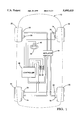
- FIG. 1 illustrates a schematic diagram of a vehicle implementing an example apparatus according to this invention
- FIG. 2 illustrates a flow diagram for an example computer controller implementation of the apparatus according to this invention
- FIGS. 3-8 illustrate example flow subroutines corresponding to the flow diagram shown in FIG. 2;
- FIG. 9 illustrates an example correlation between the index ratio according to this invention and the side slip angle of a vehicle
- FIG. 10 illustrates an example correlation between computed under steer according to this invention and the side slip angle of a vehicle
- FIG. 11 illustrates a schematic of an example apparatus according to this invention.
- the vehicle 10 includes four wheels 20, 22, 24 and 26, each with associated wheel brakes 12, 14, 16 and 18.
- Each wheel 20-26 has a wheel speed sensor 28, 30, 32 and 34 of a known type providing wheel speed information to the microprocessor-based controller 46.
- the controller 46 also receives steering wheel position information for steering wheel 42 from position sensor 40.
- Position sensor 40 may be a digital sensor that increments a digital output signal with each degree or partial degree of movement of the steering wheel 42 in one direction and decrements the digital output signal with each degree or partial degree of movement in the opposite direction.
- the steering wheel sensor 40 need not have an inherent center position signal capability, but such capability may be included to serve as a guide indicating that the steering wheel is approximately on center.
- Such steering wheel sensors 40 are well known to those skilled in the art.
- controller 46 also receives signals from yaw rate sensor 36 and lateral accelerometer 38 to effect the controls described herein.
- the controller 46 in general, controls a brake actuator or actuators 44 for controlling the wheel brakes 12, 14, 16 and 18 to provide any suitable type of chassis control for the vehicle.
- brake actuators 44 are well known to those skilled in the art and need not be set forth herein in detail.
- the active brake controls are not germane to this invention and may be any type of control presently known or in the future known to those skilled in the art, further detail of such controls are not set forth herein. Those skilled in the art will recognize that the brake control is considered generic for purposes of this description and the brake control referred to herein may encompass any known brake control.
- FIG. 2 the main control routine implemented by the brake controller 46 for performing the vehicle chassis system control method according to this invention is shown.
- the routine is continuously run on an interrupt basis by the controller 46 in conjunction with its other control tasks.
- the routine When the vehicle is first powered up, the routine performs the normal initialization tasks (block 100) required by the microprocessor within the controller 46. Then, at block 102, the routine checks a flag indicating whether or not the vehicle is off its course and intended direction.
- off course and intended direction means the vehicle is not traveling in a direction and course as normally would be directed by the vehicle tires. That is, there is an angle, referred to as the slip angle, between a line indicating the direction of actual vehicle travel and a line between the front and rear vehicle tires (either left or right). For example, if the vehicle is experiencing rotational moment involving lateral sliding engagement between the vehicle tires and the road surface, then the slip angle is greater than zero. If the slip angle achieves a predetermined level, as further defined below, the condition is detected by this invention and the off course flag is set.
- the routine continues to block 104 where it checks a flag to determine if an advanced chassis control, such as an advanced brake control, is activated. If not, the routine continues to block 106 where the active brake control flag is reset turning off active brake control. If, at block 102, the off course flag is set, the routine continues to block 106 where the active brake control flag is reset.
- an advanced chassis control such as an advanced brake control
- the active brake control flag that is reset at block 106 is used to control the active brake control in the vehicle.
- the details of the active brake control or other advanced chassis control suitable for use with this invention are known to those skilled in the art and, because they are not germane to this invention, are not set forth herein in detail. It is understood, however, that the active brake control or other advanced chassis control, such as in four wheel steer system, is responsive to the active brake control flag and is disabled when the active brake control flag is reset at block 106. From block 106, the interrupt routine is terminated.
- the routine continues to block 108 where the off course detection achieved by this invention is implemented as described below. From block 108 the routine continues to block 109 where it implements the chassis system control, such as active brake control, active four wheel steer, etc., in a manner known to those skilled in the art.
- the chassis system control such as active brake control, active four wheel steer, etc.
- the test performed at block 102 in FIG. 2 is shown in more detail as the subroutine comprising blocks 120-128.
- the subroutine starts and moves to block 120 where it checks the off course flag. If the off course flag is not set, the routine exits and moves to block 104 in FIG. 2. If, however, at block 120, the off course flag is set, the routine continues to block 124 where it forms a test to determine whether or not the vehicle is static, i.e., at a stand still or moving very slowly.
- the test performed at block 124 is shown in more detail as the subroutine 124 in FIG. 4.
- the vehicle static test subroutine starts and moves to block 110 where it checks to determine if all of the following conditions are met: (a) the vehicle speed is below a vehicle speed threshold, for example 8 kph.; (b) the absolute value of the forward acceleration of the vehicle is below an acceleration threshold, for example, 3 m/s 2 ; (c) the yaw rate is below a yaw rate threshold, for example, 1.5 deg./s; (d) the yaw acceleration is below a yaw acceleration threshold, for example 8 deg./s 2 ; (e) the lateral acceleration is below a lateral acceleration threshold, for example 5 m/s 2 ; and (f) the lateral jerk, determined as the integral of lateral acceleration, is below a lateral jerk threshold, for example 0.5 g/s.
- Vehicle speed is determined either from the vehicle speed signal from the vehicle transmission or as the average of the wheel speeds of the undriven vehicle wheels, i.e., wheels 24 and 26 (FIG. 1) for a front wheel drive vehicle.
- Forward acceleration is determined either from a forward acceleration sensor or through differentiating the vehicle speed signal.
- Yaw rate is determined, for example, from the yaw rate sensor, calibration of which may be done in the manner described in the above-mentioned copending application, Ser. No. 08/664,321.
- Yaw acceleration is determined by differentiating the yaw rate and lateral acceleration is as measured by the lateral accelerometer.
- routine 124 exits to block 126 (FIG. 3). If any of the conditions at block 210 fail, then the routine 124 exits to block 122 (FIG. 3).
- the routine compares a timer value TIMER1 to a maximum timer value, TMAX. If the TIMER1 is not greater than TMAX, then the routine continues to block 128 where it increments TIMER1 and then continues to block 106 in FIG. 2. If, however, either of the tests at blocks 124 and 122 are passed, the routine continues to block 126 where all of the off course calibration variables are reset and the subroutine 102 is exited to block 104 in FIG. 2.
- the subroutine in block 102 via blocks 122, 124 and 126, resets the off course flag if the vehicle static test is passed at block 124 or if the off course flag has been set for a predetermined time period, after which the control method shown resets the off course flag (block 136) until another off course detection (block 108, FIG. 2) is made.
- the off course detection subroutine starts and moves to block 140 where it obtains from the various vehicle sensors measurements of steering wheel angle, lateral acceleration, yaw rate and left and right rear wheel speeds.
- each of the measurement signals received at block 140 is filtered, for example, through a one pole low pass filter, to eliminate sensor noise and other signal disturbances.
- the routine moves to block 144 where a subroutine calculates an index ratio, also referred to as the stability ratio or stability index, using lateral acceleration, yaw rate and vehicle speed.
- the index ratio according to this invention is indicative of the vehicle slip angle during certain driving conditions.
- a subroutine 144 for calculating the index ratio is shown.
- the subroutine 144 starts and moves to block 170 where the absolute value of the lateral acceleration is compared to the lateral acceleration threshold, Ayl. If is greater than the lateral acceleration threshold, then the absolute value of the lateral acceleration is used in determining the index ratio at block 172. If the absolute value of the lateral acceleration is not greater than the lateral acceleration threshold, then the value Ay used for determining the index ratio is set to a predetermined minimum, for example 0.1 g.
- the index ratio is determined according to:
- the routine continues to block 146 where it compares the index ratio to an index ratio threshold, LMT1.
- LMT1 An example value for LMT1 is 2. If the index ratio is not greater than LMT1, the routine is exited. If, however, at block 146 the index ratio is greater than LMT1, the first criteria for determining an off course condition is met and the routine continues to block 148 where a subroutine for calculating the understeer index, INDEX2, is performed.
- the subroutine for calculating the understeer index 148 begins and moves to block 180 where the measured yaw rate is limited so that it is no greater than a maximum value, YAW1. Then, at block 182, the vehicle speed, v, is computed as the average speed of the two undriven wheels, for example, the left rear and left right wheels in a front wheel drive vehicle. At block 184 the vehicle speed signal is adjusted so that it is no less than the lower limit V l , for example 3 km/h.
- the routine moves to block 186 where it filters the steering wheel angle signal to remove noise and signal perturbations therefrom.
- the under steer index is computed as:
- ⁇ is the steering wheel angle and L is the distance between the front and rear wheels of the vehicle.
- the calculated under steer index determined at block 188 is then filtered at block 190 using a simple low pass filter and then the subroutine 148 is exited. It is noted that the under steer index is typically less than zero.
- the routine continues to block 150 where it compares the filtered under steer index to a second threshold, LMT2. If the filtered under steer index is greater than LMT2, the routine exits. If, at block 150, the filtered under steer index is less than LMT2, then the second criteria for determining an off course condition of the vehicle is met and the routine continues to block 152 where it performs a subroutine for determining the integral of the under steer index.
- the subroutine performed at block 152 is shown in FIG. 8, which starts and moves to block 194 where it updates LMT2 from a look-up table based on vehicle speed. The function of the look-up table is shown in block 194. For lower vehicle speeds, LMT2 is set at a fixed value, i.e., -50 but for higher vehicle speeds, LMT2 gradually reduces.
- the routine continues to block 196 where it compares the filtered under steer index to LMT2. If the filtered under steer index is not less than LMT2, the routine moves to block 198 where it sets the filtered under steer index to zero and then continues to block 200. If, at block 196, the filtered under steer index is less than LMT2, then the routine continues to block 200.
- the integral of the filtered under steer index is determined using an integrating filter.
- the routine continues to block 154 where it compares the integral of the filtered under steer index to a third threshold, LMT3.
- LMT3 is -150. If the integral of the filtered under steer index is not less than LMT3, the routine is exited. If the integral of the understeer index is less than LMT3, then the third criteria for determining an off course condition of the vehicle is met and the routine continues to block 156 where the last criteria for determining an off course condition of the vehicle is tested.
- the test at block 156 compares the absolute value of the yaw rate to the threshold LMT4.
- An example value for LMT4 is 15 deg/s. If the absolute value of the yaw rate is not greater than LMT4, no off course condition is determined and the routine exits. If, however, the absolute value of yaw rate is greater than LMT4 at block 156, then the fourth and final criteria for determining an off course condition of the vehicle is met and the routine continues to block 158 where it sets the off course flag.
- the controller 46 implements a test for determining the condition of a vehicle, whether or not the vehicle is on or off its intended course and direction.
- the controller sets a control flag for a chassis control system such as an active brake control or a four wheel steer using brake control when an off course state is determined because it is recognized that once a vehicle is off course a predetermined amount, active brake control or other advanced chassis control systems are not implemented in returning the vehicle to course.
- the graph shows the relationship between the index ratio, i.e., computed at block 144 in FIG. 5 and the side slip angle of the vehicle.
- the side slip angle of the vehicle is defined as the angle between a straight line representing the vehicle's actual direction of travel and a straight line drawn between the vehicle's front and rear left wheels (or front and rear right wheels).
- the relationship between the index ratio and the side slip angle varies as a function of speed.
- Trace 302 indicates the relationship for a vehicle traveling at 40 mph
- race 304 indicates the relationship for a vehicle traveling at 30 mph
- trace 306 indicates the relationship for a vehicle traveling at 20 mph.
- FIG. 10 illustrates the relationship between the under steer index and the side slip angle of the vehicle.
- Trace 310 illustrates the relationship between the under steer index and the side slip angle for a vehicle traveling at 40 mph
- trace 312 illustrates the relationship for a vehicle traveling at 30 mph
- trace 314 illustrates the relationship for a vehicle traveling at 20 mph.
- the example apparatus schematic of this invention shown includes, within controller 46, internal processor 350, i.e., a microprocessor, and RAM 352.
- the processor 350 receives the sensor information including the vehicle speed, yaw rate and lateral acceleration as provided by the sensors 32, 34, 36 and 38.
- sequential operations are performed according to a software control program stored in ROM (not shown) or other non-volatile memory device to effect the steps described above.
- the controller 352 computes the indexes, INDEX1 and INDEX2, that are stored in memory locations 354 and 356.
- the indexes are controls for the active brake control on/off indicator, which, in the example above, is implemented as a flag stored in processor memory or RAM.
- the on/off indicator 358 When the indexes achieve values above predetermined thresholds, the on/off indicator 358 is turned off, disabling active brake control in the processor 350 for a predetermined time period.
- timer 360 When indicator 358 is turned off, timer 360 is initiated. When the timer 360 times out, the controller switches the on/off indicator back to the "on" state until the indexes again cause the indicator 358 to be switched off.
Abstract
Description
INDEX1=|YAW.sub.-- RATE*v/Ay|,
INDEX2=((θ*v/YAW.sub.-- RATE)-L)/v,
Claims (11)
Priority Applications (3)
| Application Number | Priority Date | Filing Date | Title |
|---|---|---|---|
| US08/660,150 US5895433A (en) | 1996-05-23 | 1996-05-23 | Vehicle chassis system control method and apparatus |
| DE69709235T DE69709235T2 (en) | 1996-05-23 | 1997-04-21 | Method and device for the chassis control system of a motor vehicle |
| EP97201167A EP0808732B1 (en) | 1996-05-23 | 1997-04-21 | Vehicle chassis system control method and apparatus |
Applications Claiming Priority (1)
| Application Number | Priority Date | Filing Date | Title |
|---|---|---|---|
| US08/660,150 US5895433A (en) | 1996-05-23 | 1996-05-23 | Vehicle chassis system control method and apparatus |
Publications (1)
| Publication Number | Publication Date |
|---|---|
| US5895433A true US5895433A (en) | 1999-04-20 |
Family
ID=24648370
Family Applications (1)
| Application Number | Title | Priority Date | Filing Date |
|---|---|---|---|
| US08/660,150 Expired - Fee Related US5895433A (en) | 1996-05-23 | 1996-05-23 | Vehicle chassis system control method and apparatus |
Country Status (3)
| Country | Link |
|---|---|
| US (1) | US5895433A (en) |
| EP (1) | EP0808732B1 (en) |
| DE (1) | DE69709235T2 (en) |
Cited By (10)
| Publication number | Priority date | Publication date | Assignee | Title |
|---|---|---|---|---|
| US6204758B1 (en) * | 1999-07-23 | 2001-03-20 | Schrader-Bridgeport International, Inc. | System to automatically determine wheel position for automotive remote tire monitoring system |
| US6253602B1 (en) * | 1997-12-24 | 2001-07-03 | Nisshinbo Industries, Inc. | Method for correcting the vehicle G sensor output value and for detecting G sensor failure |
| US6427130B1 (en) * | 1997-07-02 | 2002-07-30 | Robert Bosch Gmbh | Method and device for regulating a quantity of motion representing the movement of a vehicle |
| US6430478B2 (en) * | 2000-05-31 | 2002-08-06 | Robert Bosch Gmbh | System for controlling/regulating the operational sequences in a motor vehicle and a method for starting such a system |
| US6604035B1 (en) * | 1998-12-29 | 2003-08-05 | Robert Bosch Gmbh | Device and method for stabilizing a vehicle |
| US20050149243A1 (en) * | 2004-01-06 | 2005-07-07 | Ghoneim Youssef A. | Integrating active front steering and vehicle stability brake control |
| US20050278077A1 (en) * | 2004-06-09 | 2005-12-15 | Kwang-Keun Shin | Real-time vehicle dynamics estimation system |
| CN1315677C (en) * | 1999-06-30 | 2007-05-16 | 罗伯特-博希股份公司 | Method and device for stabilizing a vehicle |
| US20090030574A1 (en) * | 2007-07-26 | 2009-01-29 | Hitachi, Ltd. | Drive Controlling Apparatus For A Vehicle |
| US20090112404A1 (en) * | 2007-10-29 | 2009-04-30 | Hitachi, Ltd. | Vehicle control apparatus |
Families Citing this family (5)
| Publication number | Priority date | Publication date | Assignee | Title |
|---|---|---|---|---|
| DE10316760A1 (en) * | 2003-04-10 | 2004-10-28 | Continental Aktiengesellschaft | Method for operating a level control system of a motor vehicle |
| DE10330895A1 (en) * | 2003-07-09 | 2005-02-17 | Daimlerchrysler Ag | Control of straight-line interference of a motor vehicle |
| DE102006030593B4 (en) * | 2006-07-03 | 2013-06-13 | Continental Automotive Gmbh | Method for rest position determination of a vehicle |
| EP2135782B1 (en) | 2008-06-18 | 2011-10-05 | GM Global Technology Operations LLC | Motor vehicle driver assisting method near the stability limit |
| DE102010003951A1 (en) * | 2010-04-14 | 2011-10-20 | Robert Bosch Gmbh | Method for stabilizing a two-wheeler with laterally slipping rear wheel |
Citations (26)
| Publication number | Priority date | Publication date | Assignee | Title |
|---|---|---|---|---|
| US4695068A (en) * | 1985-01-24 | 1987-09-22 | Honda Giken Kogyo Kabushiki Kaisha | Front and rear wheel steering device |
| US5063514A (en) * | 1990-06-19 | 1991-11-05 | General Motors Corporation | Abs yaw control |
| JPH04135976A (en) * | 1990-09-28 | 1992-05-11 | Aisin Seiki Co Ltd | Four wheel steering device |
| DE4123235C1 (en) * | 1991-07-13 | 1992-11-26 | Daimler Benz Ag | |
| US5172961A (en) * | 1990-07-05 | 1992-12-22 | Nissan Motor Co. Ltd. | Vehicle brake system including cornering characteristic control |
| DE4121954A1 (en) * | 1991-07-03 | 1993-01-07 | Bosch Gmbh Robert | METHOD FOR OBTAINING THE YEAR SPEED AND / OR THE LATERAL SPEED |
| GB2257551A (en) * | 1991-07-12 | 1993-01-13 | Bosch Gmbh Robert | Determination of a parameter of motion of a vehicle |
| JPH05139327A (en) * | 1991-11-15 | 1993-06-08 | Toyota Motor Corp | Vehicle motion controller |
| DE4200061A1 (en) * | 1992-01-03 | 1993-07-08 | Bosch Gmbh Robert | METHOD FOR DETERMINING THE VEHICLE CROSS SPEED AND / OR THE SWIMMING ANGLE |
| GB2263340A (en) * | 1992-01-16 | 1993-07-21 | Steyr Daimler Puch Ag | Method for determining the dynamic safety margin of motor vehicles |
| EP0555860A1 (en) * | 1992-02-14 | 1993-08-18 | Honda Giken Kogyo Kabushiki Kaisha | Steering stability control system for vehicle |
| EP0557692A1 (en) * | 1992-01-31 | 1993-09-01 | Robert Bosch Gmbh | Apparatus for controlling the steering angle |
| DE4208000A1 (en) * | 1992-03-13 | 1993-09-16 | Bosch Gmbh Robert | Detecting incorrect teeth count in inductive sensor in vehicle - measuring and comparing wheel speed measurements during acceleration period and generating appropriate warning signal |
| DE4223385A1 (en) * | 1992-07-16 | 1994-01-20 | Bosch Gmbh Robert | Detecting reverse motion of motor vehicle for brake control system - measuring yaw rate, vehicle speed, wheel state and steering angle and using given equations to derive forward or reverse motion signals |
| GB2269571A (en) * | 1992-08-13 | 1994-02-16 | Daimler Benz Ag | Process for determining quantities characterising vehicle travel behaviour. |
| DE4229504A1 (en) * | 1992-09-04 | 1994-03-10 | Bosch Gmbh Robert | Vehicle road-curve stability regulation procedure - involves regulation of actual yaw velocity by comparison with required value as calculated from detected parameters |
| US5315519A (en) * | 1991-10-03 | 1994-05-24 | General Motors Corporation | Method of sensing excessive slip in a wheel slip control system |
| GB2275312A (en) * | 1993-02-19 | 1994-08-24 | Bosch Gmbh Robert | Vehicle movement dynamics control system |
| DE4311077A1 (en) * | 1993-04-03 | 1994-10-06 | Bosch Gmbh Robert | Anti-lock control system |
| DE4314827A1 (en) * | 1993-05-05 | 1994-11-10 | Porsche Ag | Method for determining the yaw velocity of a vehicle |
| US5444621A (en) * | 1991-06-10 | 1995-08-22 | Nippondenso Co., Ltd. | Suspension control system for controlling suspension of automotive vehicle based on wheel speed data |
| US5465210A (en) * | 1994-08-18 | 1995-11-07 | General Motors Corporation | Method for determining a vehicle steering wheel center position |
| EP0682614A1 (en) * | 1991-07-06 | 1995-11-22 | Teves Gmbh Alfred | Circuit for detecting defects in wheel sensors. |
| JPH0820324A (en) * | 1994-07-04 | 1996-01-23 | Tokyo Buhin Kogyo Kk | Control method and device for auxiliary brake |
| JPH0840246A (en) * | 1994-07-26 | 1996-02-13 | Hino Motors Ltd | Brake device for vehicle |
| US5717591A (en) * | 1994-09-13 | 1998-02-10 | Toyota Jidosha Kabushiki Kaisha | Turn behavior control system of vehicle adaptable to external conditions |
-
1996
- 1996-05-23 US US08/660,150 patent/US5895433A/en not_active Expired - Fee Related
-
1997
- 1997-04-21 DE DE69709235T patent/DE69709235T2/en not_active Expired - Lifetime
- 1997-04-21 EP EP97201167A patent/EP0808732B1/en not_active Expired - Lifetime
Patent Citations (28)
| Publication number | Priority date | Publication date | Assignee | Title |
|---|---|---|---|---|
| US4695068A (en) * | 1985-01-24 | 1987-09-22 | Honda Giken Kogyo Kabushiki Kaisha | Front and rear wheel steering device |
| US5063514A (en) * | 1990-06-19 | 1991-11-05 | General Motors Corporation | Abs yaw control |
| US5172961A (en) * | 1990-07-05 | 1992-12-22 | Nissan Motor Co. Ltd. | Vehicle brake system including cornering characteristic control |
| JPH04135976A (en) * | 1990-09-28 | 1992-05-11 | Aisin Seiki Co Ltd | Four wheel steering device |
| US5444621A (en) * | 1991-06-10 | 1995-08-22 | Nippondenso Co., Ltd. | Suspension control system for controlling suspension of automotive vehicle based on wheel speed data |
| DE4121954A1 (en) * | 1991-07-03 | 1993-01-07 | Bosch Gmbh Robert | METHOD FOR OBTAINING THE YEAR SPEED AND / OR THE LATERAL SPEED |
| EP0682614A1 (en) * | 1991-07-06 | 1995-11-22 | Teves Gmbh Alfred | Circuit for detecting defects in wheel sensors. |
| GB2257551A (en) * | 1991-07-12 | 1993-01-13 | Bosch Gmbh Robert | Determination of a parameter of motion of a vehicle |
| DE4123235C1 (en) * | 1991-07-13 | 1992-11-26 | Daimler Benz Ag | |
| US5341297A (en) * | 1991-07-13 | 1994-08-23 | Mercedes-Benz Ag | Apparatus and method for preventing instabilities in vehicle handling |
| US5315519A (en) * | 1991-10-03 | 1994-05-24 | General Motors Corporation | Method of sensing excessive slip in a wheel slip control system |
| JPH05139327A (en) * | 1991-11-15 | 1993-06-08 | Toyota Motor Corp | Vehicle motion controller |
| DE4200061A1 (en) * | 1992-01-03 | 1993-07-08 | Bosch Gmbh Robert | METHOD FOR DETERMINING THE VEHICLE CROSS SPEED AND / OR THE SWIMMING ANGLE |
| GB2263340A (en) * | 1992-01-16 | 1993-07-21 | Steyr Daimler Puch Ag | Method for determining the dynamic safety margin of motor vehicles |
| EP0557692A1 (en) * | 1992-01-31 | 1993-09-01 | Robert Bosch Gmbh | Apparatus for controlling the steering angle |
| EP0555860A1 (en) * | 1992-02-14 | 1993-08-18 | Honda Giken Kogyo Kabushiki Kaisha | Steering stability control system for vehicle |
| DE4208000A1 (en) * | 1992-03-13 | 1993-09-16 | Bosch Gmbh Robert | Detecting incorrect teeth count in inductive sensor in vehicle - measuring and comparing wheel speed measurements during acceleration period and generating appropriate warning signal |
| DE4223385A1 (en) * | 1992-07-16 | 1994-01-20 | Bosch Gmbh Robert | Detecting reverse motion of motor vehicle for brake control system - measuring yaw rate, vehicle speed, wheel state and steering angle and using given equations to derive forward or reverse motion signals |
| GB2269571A (en) * | 1992-08-13 | 1994-02-16 | Daimler Benz Ag | Process for determining quantities characterising vehicle travel behaviour. |
| US5402342A (en) * | 1992-09-04 | 1995-03-28 | Robert Bosch Gmbh | Method for controlling motor vehicle stability |
| DE4229504A1 (en) * | 1992-09-04 | 1994-03-10 | Bosch Gmbh Robert | Vehicle road-curve stability regulation procedure - involves regulation of actual yaw velocity by comparison with required value as calculated from detected parameters |
| GB2275312A (en) * | 1993-02-19 | 1994-08-24 | Bosch Gmbh Robert | Vehicle movement dynamics control system |
| DE4311077A1 (en) * | 1993-04-03 | 1994-10-06 | Bosch Gmbh Robert | Anti-lock control system |
| DE4314827A1 (en) * | 1993-05-05 | 1994-11-10 | Porsche Ag | Method for determining the yaw velocity of a vehicle |
| JPH0820324A (en) * | 1994-07-04 | 1996-01-23 | Tokyo Buhin Kogyo Kk | Control method and device for auxiliary brake |
| JPH0840246A (en) * | 1994-07-26 | 1996-02-13 | Hino Motors Ltd | Brake device for vehicle |
| US5465210A (en) * | 1994-08-18 | 1995-11-07 | General Motors Corporation | Method for determining a vehicle steering wheel center position |
| US5717591A (en) * | 1994-09-13 | 1998-02-10 | Toyota Jidosha Kabushiki Kaisha | Turn behavior control system of vehicle adaptable to external conditions |
Non-Patent Citations (10)
| Title |
|---|
| Automobiles May the Cornering Force be with You, Popular Mechanics Dec., 1995; pp. 74 77. * |
| Automobiles--May the Cornering Force be with You, Popular Mechanics Dec., 1995; pp. 74-77. |
| Consideration of Lateral & Longitudinal Vehicle Stability by Function Enhanced Brake & Stability Control System, SAE #940832, pp. 63-72. |
| Consideration of Lateral & Longitudinal Vehicle Stability by Function Enhanced Brake & Stability Control System, SAE 940832, pp. 63 72. * |
| Control of Vehicle Dynamics, Automotive Engineering, May 1995, pp. 87 93. * |
| Control of Vehicle Dynamics, Automotive Engineering, May 1995, pp. 87-93. |
| Spin Control for Cars, Steven Ashley, Associate Editor, Mechanical Engineering Jun., 1995, pp. 66 68. * |
| Spin Control for Cars, Steven Ashley, Associate Editor, Mechanical Engineering Jun., 1995, pp. 66-68. |
| Technoid: Intelligent Brakes are on the way; Car and Driver Magazine; Aug. 1994. * |
| The Spin Doctors, Don Sherman; 12PS95 Controlling Vehicle Stability; C.A. Sawyer; Automotive Industries; Jan. 1995; pp. 48 & 50. * |
Cited By (20)
| Publication number | Priority date | Publication date | Assignee | Title |
|---|---|---|---|---|
| US6427130B1 (en) * | 1997-07-02 | 2002-07-30 | Robert Bosch Gmbh | Method and device for regulating a quantity of motion representing the movement of a vehicle |
| US6253602B1 (en) * | 1997-12-24 | 2001-07-03 | Nisshinbo Industries, Inc. | Method for correcting the vehicle G sensor output value and for detecting G sensor failure |
| US6604035B1 (en) * | 1998-12-29 | 2003-08-05 | Robert Bosch Gmbh | Device and method for stabilizing a vehicle |
| CN1315677C (en) * | 1999-06-30 | 2007-05-16 | 罗伯特-博希股份公司 | Method and device for stabilizing a vehicle |
| US6204758B1 (en) * | 1999-07-23 | 2001-03-20 | Schrader-Bridgeport International, Inc. | System to automatically determine wheel position for automotive remote tire monitoring system |
| US6430478B2 (en) * | 2000-05-31 | 2002-08-06 | Robert Bosch Gmbh | System for controlling/regulating the operational sequences in a motor vehicle and a method for starting such a system |
| US7698034B2 (en) * | 2004-01-06 | 2010-04-13 | Gm Global Technology Operations, Inc. | Integrating active front steering and vehicle stability brake control |
| US20050149243A1 (en) * | 2004-01-06 | 2005-07-07 | Ghoneim Youssef A. | Integrating active front steering and vehicle stability brake control |
| US7487021B2 (en) * | 2004-06-09 | 2009-02-03 | General Motors Corporation | Method for determining estimated vehicle dynamics parameters |
| US20050278077A1 (en) * | 2004-06-09 | 2005-12-15 | Kwang-Keun Shin | Real-time vehicle dynamics estimation system |
| US20070276564A1 (en) * | 2004-06-09 | 2007-11-29 | Gm Global Technology Operations, Inc. | Method for Determining Estimated Vehicle Dynamics Parameters |
| US7349778B2 (en) * | 2004-06-09 | 2008-03-25 | General Motors Corporation | Real-time vehicle dynamics estimation system |
| WO2006001948A2 (en) * | 2004-06-09 | 2006-01-05 | General Motors Corporation | Real-time vehicle dynamics estimation system |
| WO2006001948A3 (en) * | 2004-06-09 | 2006-12-28 | Gen Motors Corp | Real-time vehicle dynamics estimation system |
| CN101002151B (en) * | 2004-06-09 | 2010-12-08 | 通用汽车公司 | Real-time vehicle dynamics estimation system |
| US20090030574A1 (en) * | 2007-07-26 | 2009-01-29 | Hitachi, Ltd. | Drive Controlling Apparatus For A Vehicle |
| US8744689B2 (en) * | 2007-07-26 | 2014-06-03 | Hitachi, Ltd. | Drive controlling apparatus for a vehicle |
| US9145165B2 (en) | 2007-07-26 | 2015-09-29 | Hitachi, Ltd. | Drive controlling apparatus for a vehicle |
| US20090112404A1 (en) * | 2007-10-29 | 2009-04-30 | Hitachi, Ltd. | Vehicle control apparatus |
| US7853366B2 (en) * | 2007-10-29 | 2010-12-14 | Hitachi, Ltd. | Vehicle control apparatus |
Also Published As
| Publication number | Publication date |
|---|---|
| DE69709235D1 (en) | 2002-01-31 |
| EP0808732B1 (en) | 2001-12-19 |
| EP0808732A1 (en) | 1997-11-26 |
| DE69709235T2 (en) | 2002-08-22 |
Similar Documents
| Publication | Publication Date | Title |
|---|---|---|
| US5895433A (en) | Vehicle chassis system control method and apparatus | |
| EP0809167B1 (en) | Method for providing a steering position signal | |
| US5343741A (en) | System for determining pneumatic tire pressure for motor vehicle by comparing actual to adequate wheel rotational speed | |
| EP0650856B1 (en) | System for determining pneumatic tire pressure for motor vehicle by comparison of rotational wheel speeds | |
| EP0983919B1 (en) | A method for detecting a bank angle experienced by a moving vehicle | |
| US5826210A (en) | Tire air pressure warining device | |
| US5700073A (en) | Braking force control system and the method thereof | |
| EP1085993B1 (en) | Vehicle roll control | |
| US8000872B2 (en) | Vehicle anti-skid brake control system and its control method | |
| US6697728B2 (en) | Vehicle motion control system | |
| JP3800901B2 (en) | Lane tracking control device | |
| KR19990077631A (en) | Device for estimating rolling condition of vehicle body with limits of roll angle and angular speed | |
| JP2620310B2 (en) | Wheel behavior detector | |
| US6285933B1 (en) | Device and method for monitoring a transverse acceleration sensor located in a vehicle | |
| US5172318A (en) | Method for the detection of curves and the determination of the transverse acceleration in a vehicle | |
| EP0747282B1 (en) | Method for determining a centre position of a vehicle steering system | |
| US5040115A (en) | System for monitoring vehicle slip angle | |
| US6834222B2 (en) | Tire imbalance detection system and method using anti-lock brake wheel speed sensors | |
| US5016179A (en) | Drive slip regulator for motor vehicles | |
| US5931880A (en) | System for determining skew stiffness | |
| US20050182542A1 (en) | Device and procedure for a steering support for vehicles with electromechanical steering system | |
| US6456923B1 (en) | Method for detecting cornering for a vehicle with an automatic transmission | |
| JPS60191875A (en) | Controlling method of steerage for vehicles | |
| JPH08332934A (en) | Skidding condition quantity detection device for vehicle | |
| JP3190149B2 (en) | Control gain changing device for automotive control unit |
Legal Events
| Date | Code | Title | Description |
|---|---|---|---|
| AS | Assignment |
Owner name: GENERAL MOTORS CORPORATION, MICHIGAN Free format text: ASSIGNMENT OF ASSIGNORS INTEREST;ASSIGNORS:CHEN, HSIEN HENG;LEAPHART, ELDON GERRALD;BEDNER, EDWARD JOHN;AND OTHERS;REEL/FRAME:008044/0330;SIGNING DATES FROM 19960425 TO 19960503 |
|
| FPAY | Fee payment |
Year of fee payment: 4 |
|
| FPAY | Fee payment |
Year of fee payment: 8 |
|
| AS | Assignment |
Owner name: GM GLOBAL TECHNOLOGY OPERATIONS, INC., MICHIGAN Free format text: ASSIGNMENT OF ASSIGNORS INTEREST;ASSIGNOR:GENERAL MOTORS CORPORATION;REEL/FRAME:022117/0047 Effective date: 20050119 Owner name: GM GLOBAL TECHNOLOGY OPERATIONS, INC.,MICHIGAN Free format text: ASSIGNMENT OF ASSIGNORS INTEREST;ASSIGNOR:GENERAL MOTORS CORPORATION;REEL/FRAME:022117/0047 Effective date: 20050119 |
|
| AS | Assignment |
Owner name: UNITED STATES DEPARTMENT OF THE TREASURY, DISTRICT Free format text: SECURITY AGREEMENT;ASSIGNOR:GM GLOBAL TECHNOLOGY OPERATIONS, INC.;REEL/FRAME:022201/0501 Effective date: 20081231 |
|
| AS | Assignment |
Owner name: CITICORP USA, INC. AS AGENT FOR HEDGE PRIORITY SEC Free format text: SECURITY AGREEMENT;ASSIGNOR:GM GLOBAL TECHNOLOGY OPERATIONS, INC.;REEL/FRAME:022556/0013 Effective date: 20090409 Owner name: CITICORP USA, INC. AS AGENT FOR BANK PRIORITY SECU Free format text: SECURITY AGREEMENT;ASSIGNOR:GM GLOBAL TECHNOLOGY OPERATIONS, INC.;REEL/FRAME:022556/0013 Effective date: 20090409 |
|
| AS | Assignment |
Owner name: GM GLOBAL TECHNOLOGY OPERATIONS, INC., MICHIGAN Free format text: RELEASE BY SECURED PARTY;ASSIGNOR:UNITED STATES DEPARTMENT OF THE TREASURY;REEL/FRAME:023238/0015 Effective date: 20090709 |
|
| XAS | Not any more in us assignment database |
Free format text: RELEASE BY SECURED PARTY;ASSIGNOR:UNITED STATES DEPARTMENT OF THE TREASURY;REEL/FRAME:023124/0383 |
|
| AS | Assignment |
Owner name: GM GLOBAL TECHNOLOGY OPERATIONS, INC., MICHIGAN Free format text: RELEASE BY SECURED PARTY;ASSIGNORS:CITICORP USA, INC. AS AGENT FOR BANK PRIORITY SECURED PARTIES;CITICORP USA, INC. AS AGENT FOR HEDGE PRIORITY SECURED PARTIES;REEL/FRAME:023127/0326 Effective date: 20090814 |
|
| AS | Assignment |
Owner name: UNITED STATES DEPARTMENT OF THE TREASURY, DISTRICT Free format text: SECURITY AGREEMENT;ASSIGNOR:GM GLOBAL TECHNOLOGY OPERATIONS, INC.;REEL/FRAME:023155/0922 Effective date: 20090710 |
|
| AS | Assignment |
Owner name: UAW RETIREE MEDICAL BENEFITS TRUST, MICHIGAN Free format text: SECURITY AGREEMENT;ASSIGNOR:GM GLOBAL TECHNOLOGY OPERATIONS, INC.;REEL/FRAME:023161/0864 Effective date: 20090710 |
|
| REMI | Maintenance fee reminder mailed | ||
| LAPS | Lapse for failure to pay maintenance fees | ||
| STCH | Information on status: patent discontinuation |
Free format text: PATENT EXPIRED DUE TO NONPAYMENT OF MAINTENANCE FEES UNDER 37 CFR 1.362 |
|
| FP | Lapsed due to failure to pay maintenance fee |
Effective date: 20110420 |