US5902925A - System and method for high accuracy calibration of a sensor for offset and sensitivity variation with temperature - Google Patents
System and method for high accuracy calibration of a sensor for offset and sensitivity variation with temperature Download PDFInfo
- Publication number
- US5902925A US5902925A US08/674,028 US67402896A US5902925A US 5902925 A US5902925 A US 5902925A US 67402896 A US67402896 A US 67402896A US 5902925 A US5902925 A US 5902925A
- Authority
- US
- United States
- Prior art keywords
- temperature
- sensor
- providing
- register
- registers
- Prior art date
- Legal status (The legal status is an assumption and is not a legal conclusion. Google has not performed a legal analysis and makes no representation as to the accuracy of the status listed.)
- Expired - Lifetime
Links
Images


Classifications
-
- G—PHYSICS
- G01—MEASURING; TESTING
- G01D—MEASURING NOT SPECIALLY ADAPTED FOR A SPECIFIC VARIABLE; ARRANGEMENTS FOR MEASURING TWO OR MORE VARIABLES NOT COVERED IN A SINGLE OTHER SUBCLASS; TARIFF METERING APPARATUS; MEASURING OR TESTING NOT OTHERWISE PROVIDED FOR
- G01D3/00—Indicating or recording apparatus with provision for the special purposes referred to in the subgroups
- G01D3/028—Indicating or recording apparatus with provision for the special purposes referred to in the subgroups mitigating undesired influences, e.g. temperature, pressure
- G01D3/036—Indicating or recording apparatus with provision for the special purposes referred to in the subgroups mitigating undesired influences, e.g. temperature, pressure on measuring arrangements themselves
- G01D3/0365—Indicating or recording apparatus with provision for the special purposes referred to in the subgroups mitigating undesired influences, e.g. temperature, pressure on measuring arrangements themselves the undesired influence being measured using a separate sensor, which produces an influence related signal
Definitions
- the present invention relates generally to sensors and more particularly to improving the calibration of such sensors.
- Piezoresistive and capacitive sensors are being used in increasingly higher accuracy applications for sensing various changes in pressure and the like in a variety of environments. Because the output of these sensors typically varies over temperature, the sensors require compensation and calibration in order to achieve the accuracy and temperature stability requirements of these applications. The calibration of sensors typically requires the adjustment of four parameters to achieve optimum output performance over temperature--offset, offset temperature coefficient (OTC), signal gain, and gain temperature coefficient (GTC).
- OTC offset temperature coefficient
- GTC gain temperature coefficient
- Vsens is the sensor output voltage
- Offset 0 is the sensor offset (output with zero excitation) at a reference temperature (e.g. 25° C.)
- ⁇ 1 is the first order temperature coefficient of the sensor offset
- ⁇ 2 is the second order temperature coefficient of the sensor offset
- ⁇ n is the n th order temperature coefficient of the sensor offset
- T is the temperature difference from the reference temperature
- S 0 is the sensor sensitivity or span at the reference temperature (e.g. 25° C.)
- ⁇ 1 is the first order temperature coefficient of the sensor sensitivity
- ⁇ 2 is the second order temperature coefficient of the sensor sensitivity
- ⁇ n is the n th order temperature coefficient of the sensor sensitivity
- Q is the physical parameter being sensed (e.g. pressure, acceleration, etc.)
- Equation 1 For most sensor applications, all but the first order terms can be ignored so that Equation 1 becomes:
- Equation 1 Equation 1
- a signal conditioning circuit which must subtract out the offset terms and provide amplification which varies with temperature to counteract the effect of the sensor span (TC).
- TC sensor span
- the signal conditioning has been done with opamps and laser trimmed resistors.
- this type of signal conditioning circuit is usually limited to providing first order correction of the temperature dependent terms.
- this method is expensive as it requires the use of a laser and the solution is typically not monolithic (on a single integrated circuit) as the opamps and resistors are usually built on separate substrates.
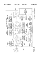
- FIG. 1 An embodiment of a conventional digital compensation circuit 100 is shown in FIG. 1.
- the differential signal from the sensor 5' is fed into an amplifier 102 which may have a gain of 1 or greater depending on the application.
- the output of this amplifier is fed into another amplifier stage 104 whose gain is controlled by the contents of a gain register 106.
- the offset and offset TC terms are added at summation point 114 in this stage using DACs 108, 110, 112 controlled by digital parameters.
- the compensation of the sensor sensitivity TC is done in the third stage 116 after the offset, offset TC and gain compensation.
- the third stage 116 may also have a gain of 1 or greater depending on the application.
- the final stage is an output buffer 111.
- the temperature, T is sensed using an on-chip proportional to absolute temperature (PTAT) circuit 122.
- the analog signal representing T is digitized using an analog-to-digital converter 124.
- the digital word representing T is then used to control two DACs 110 and 120, one for the offset TC compensation and the other for the gain TC compensation
- Digital information representing the values of the compensation terms is serially fed into an on-chip control unit 125.
- the individual bits are decoded and sent to the various DACs 108, 110, 112, and 118.
- the code is stored using a digital storage method such as zener-zap, EEPROM or fuse link.
- Equation 4 The transfer function of this circuit 100 is given by Equation 4.
- Vout is the calibrated sensor output voltage (output of conditioning circuit)
- Gain 0 is the gain of the compensating amplifier at the reference temperature
- Voff is the offset added by the conditioning circuit
- Votc ⁇ T is the temperature dependent component of the offset added by the conditioning circuit
- ⁇ is the temperature dependent component of the gain of the compensating amplifier which counteracts the temperature dependent component of the sensor sensitivity
- the calibration of the sensor involves making measurements of Vout at various values of Q and various temperatures and thereby deducing the values of Voff, Votc, Gain 0 and ⁇ to minimize the error between Vout and the ideal sensor characteristic.
- Voff, and Gain 0 terms would be found first using measurements at the initial calibration temperature at minimum and maximum Q. The temperature dependent terms would then be found by an additional set of measurements at high (or low) temperature.
- Votc -Offset 0 ⁇ 1
- equation 5 becomes:
- the desired term is simply S 0 ⁇ Q ⁇ Gain 0 . All the other terms arise because this circuit only corrects for linear variations of the sensor offset and sensitivity with temperature. In high accuracy applications these extra terms may limit the usability of the sensor since it may be impossible to calibrate the sensor within the desired specification.
- the compensator circuit comprises a serial communication circuit for receiving data relating to a plurality of parameters, and means coupled to serial communication circuit for providing piece-wise linear compensation of a temperature coefficient (TC).
- TC temperature coefficient
- the piece-wise linear compensation means further comprises detector means for detecting a threshold for a digital temperature and providing an output, and a plurality of registers coupled to the detector means and the serial communication circuit, a first of the plurality of registers for providing a first value if the digital temperature is above the threshold, a second of the plurality of registers for providing a second value if the digital temperature is below the threshold.
- the piece-wise linear compensation means further includes a selector means coupled to the detector means and the plurality of registers, for selecting one of the first and second of the plurality of registers dependent upon the output of the detector means for providing piece-wise linear compensation of a temperature coefficient.
- FIG. 1 is a diagram of a sensor conventional calibration circuit.
- FIG. 2 is a block diagram of a high accuracy calibration system 200 in accordance with the present invention.
- FIG. 3 shows typical sensor offset behavior together with a linear approximation and a piece-wise-linear approximation using the present invention.
- FIG. 4 illustrates the residual errors in the offset term for both the linear approximation and the piece-wise-linear approximation method.
- FIG. 5 illustrates a multi-part piece-wise-linear function
- the present invention relates to an improvement of a calibration system for a sensor.
- the following description is presented to enable one of ordinary skill in the art to make and use the invention and is provided in the context of a patent application and its requirements.
- Various modifications to the preferred embodiment will be readily apparent to those skilled in the art and the generic principles herein may be applied to other embodiments.
- the present invention is not intended to be limited to the embodiment shown but is to be accorded the widest scope consistent with the principles and features described herein.
- the present invention is an improvement over conventional calibration schemes.
- the second order behavior of sensor offset and sensitivity with temperature are approximated by a piece-wise-linear function.
- the offset and sensitivity behavior is approximated by two different linear functions, one for low temperature and one for high temperature.
- the switch-over point from one function to another is known as the pivot temperature and is the value at which the temperature T is zero (reference temperature). In so doing a highly accurate sensor calibration is provided.
- FIG. 2 is a block diagram of a high accuracy calibration system 200 in accordance with the present invention. As is seen system 200 has many of the common components as those shown in system 100 of FIG. 1. Those components are given similar designations as described in FIG. 1.
- the piece-wise-linear approximation for offset TC correction is implemented by providing two offset TC registers 204 and 206.
- the value in one register 204 is fed to the offset TC DAC 214 for low temperature and the value in the other register is fed to the offset TC DAC 214 for high temperature.
- the circuit 212 detects when the temperature crosses the zero point and switches the inputs to the offset TC DAC 214 from one register to the other.
- the piece-wise linear approximation for gain TC correction is implemented by two gain TC registers 208 and 210.
- the value in one register 208 is fed to the gain TC DAC 216 for low temperature and the value in the other register 210 is fed to the gain TC DAC 216 for high temperature.
- the circuit 212 detects when the temperature crosses the zero point and switches the inputs to the DAC from one register to the other.
- the temperature T is represented as a ten (10) bit digital word with 512 being the value at the pivot temperature.
- the detector circuit for the pivot temperature is, for example, a simple logic inverter connected to the most-significant-bit (MSB) of the temperature word.
- MSB most-significant-bit
- the digital temperature word is greater than or equal to 512 and therefore, the temperature T is greater than or equal to zero. If the MSB is logic 0, the digital temperature word is less than 512 and therefore T is less than zero.
- FIG. 3 shows typical sensor offset behavior 302 together with a linear approximation 304 such as that provided by the circuit 100 in FIG. 1 and a piece-wise-linear approximation 306 such as that provided by the circuit 200 of FIG. 2 of the present invention.
- a piece-wise linear approximation more closely follows the offset behavior.
- a piece-wise-linear approximation can be used for correcting the sensitivity temperature behavior.
- FIG. 4 is a waveform that shows the residual errors in the offset term for both the linear approximation 402 and the piece-wise linear approximation 404. As is seen, the piece-wise-linear approximation error is clearly smaller thus allowing for higher accuracy compensation.
- Votc a ⁇ T in segment 2 and Votc a ⁇ T 1 +Votc b ⁇ (T 2 -T 2 ) in segment 3 can be inserted into the signal path via another offset DAC or they can be combined with Voff and inserted using the existing offset DAC. Since these terms are known at time of calibration they can be stored in memory and simply added in at the appropriate temperature.
- the detection circuit would therefore include an adder circuit to calculate the extra terms in addition to calculating the terms T-T 1 and T-T 2 .
- the preferred embodiment ony includes means for providing piece-wise-linearcompensation for sensor offset TC and sensitivity TC it should be clear that the present invention can also be used to correct for the temperature coefficient of the sensor linearity error.
- the sensor linearity error is the deviation of the sensor transfer characteristic (that is, sensor output versus Q where Q is the parameter being sensed) from an ideal straight line.
- a particular sensor may require piece-wise linear compensation of offset TC or of sensitivity TC or of linearity TC and it would be within the spirit and scope of the present invention to provide piece-wise-linear compensation only of those parameters requiring it.
Abstract
Description
Vsens=Offset.sub.0 ·(1+α.sub.1 ·T+α.sub.2 ·T.sup.2 + . . . +α.sub.n ·T.sup.n)+S.sub.0 ·(1+β.sub.1 ·T+β.sub.2 ·T.sup.2 + . . . +β.sub.n ·T.sup.n)·Q Equation 1
Vsens=Offset.sub.0 ·(1+α·T)+S.sub.0 ·(1+β·T)·Q Equation 2
Vsens=Offset.sub.0 ·(1+α.sub.1 ·T+α.sub.2 ·T.sup.2)+S.sub.0 ·(1+β.sub.1 ·T+β.sub.2 ·T.sup.2)·Q Equation 3
Vout=(Vsens+Voff+Votc·T)·Gain.sub.0 ·(1+δ·T) Equation 4
Vout= S.sub.0 ·Q·(1+β.sub.1 ·T+β.sub.2 ·T.sup.C)+Offset.sub.0 ·(1+α.sub.1 ·T+α.sub.2 ·T.sup.2)·+Voff+Votc·T·!·Gain.sub.0 ·(1+δ·T)Equation 5
Vout=S.sub.0 ·Q·Gain.sub.0 · 1+T.sup.2 ·(β.sub.2 +δ·β.sub.1).sub.2 +T.sup.3 ·δ·β.sub.2 !+Offset.sub.0 ·α.sub.2 ·Gain.sub.0 ·(1+δ·T)·T.sup.2 Equation 6
CompensatingOffset=Voff+Votc.sub.a ·T Equation 7a
CompensatingOffset=Voff+Votc.sub.a ·T.sub.1 +Votc.sub.b ·(T-T.sub.1) Equation 7b
CompensatingOffset=Voff+Votc.sub.a ·T.sub.1 +Votc.sub.b ·(T.sub.2 -T.sub.1)+Vofc.sub.c ·(T-T.sub.2)Equation 7c
Claims (8)
Priority Applications (7)
| Application Number | Priority Date | Filing Date | Title |
|---|---|---|---|
| US08/674,028 US5902925A (en) | 1996-07-01 | 1996-07-01 | System and method for high accuracy calibration of a sensor for offset and sensitivity variation with temperature |
| DE69739790T DE69739790D1 (en) | 1996-07-01 | 1997-07-01 | SYSTEM AND METHOD FOR HIGH GENUINE TEMPERATURE CALIBRATION OF A SENSOR |
| AU36452/97A AU3645297A (en) | 1996-07-01 | 1997-07-01 | A system and method for high accuracy calibration of a sensor for offset and sensitivity variation with temperature |
| JP50605098A JP3415631B2 (en) | 1996-07-01 | 1997-07-01 | System and method for accurate calibration of sensors for offset and sensitivity variations due to temperature |
| EP97933210A EP0909378B1 (en) | 1996-07-01 | 1997-07-01 | A system and method for high accuracy calibration of a sensor for offset and sensitivity variation with temperature |
| PCT/US1997/011315 WO1998002721A2 (en) | 1996-07-01 | 1997-07-01 | Calibration of a sensor with temperature variations |
| CA002259378A CA2259378A1 (en) | 1996-07-01 | 1997-07-01 | A system and method for high accuracy calibration of a sensor for offset and sensitivity variation with temperature |
Applications Claiming Priority (1)
| Application Number | Priority Date | Filing Date | Title |
|---|---|---|---|
| US08/674,028 US5902925A (en) | 1996-07-01 | 1996-07-01 | System and method for high accuracy calibration of a sensor for offset and sensitivity variation with temperature |
Publications (1)
| Publication Number | Publication Date |
|---|---|
| US5902925A true US5902925A (en) | 1999-05-11 |
Family
ID=24705039
Family Applications (1)
| Application Number | Title | Priority Date | Filing Date |
|---|---|---|---|
| US08/674,028 Expired - Lifetime US5902925A (en) | 1996-07-01 | 1996-07-01 | System and method for high accuracy calibration of a sensor for offset and sensitivity variation with temperature |
Country Status (7)
| Country | Link |
|---|---|
| US (1) | US5902925A (en) |
| EP (1) | EP0909378B1 (en) |
| JP (1) | JP3415631B2 (en) |
| AU (1) | AU3645297A (en) |
| CA (1) | CA2259378A1 (en) |
| DE (1) | DE69739790D1 (en) |
| WO (1) | WO1998002721A2 (en) |
Cited By (24)
| Publication number | Priority date | Publication date | Assignee | Title |
|---|---|---|---|---|
| US6032109A (en) * | 1996-10-21 | 2000-02-29 | Telemonitor, Inc. | Smart sensor module |
| US20020020075A1 (en) * | 1995-10-03 | 2002-02-21 | Dall'aglio Carlo | Apparatus for checking diametral dimensions of cylindrical parts rotating with an orbital motion |
| US20030009895A1 (en) * | 2000-03-06 | 2003-01-16 | Dall'aglio Carlo | Apparatus and methods for measuring the pin diameter of a crankshaft at the place of grinding |
| US6644092B1 (en) * | 2001-05-14 | 2003-11-11 | Robert J. Oppel | Automatic calibration of pressure sensors for paint booth airflow control |
| US6813925B2 (en) * | 2002-06-05 | 2004-11-09 | General Electric Company | Calibration method and system for a dynamic combustor sensor |
| US20050256660A1 (en) * | 2004-05-13 | 2005-11-17 | Ami Semiconductor, Inc. | Pade' approximant based compensation for integrated sensor modules and the like |
| US20050283330A1 (en) * | 2004-06-16 | 2005-12-22 | Laraia Jose M | Reactive sensor modules using pade' approximant based compensation and providing module-sourced excitation |
| US20060265167A1 (en) * | 2005-05-04 | 2006-11-23 | Laraia Jose M | Providing nonlinear temperature compensation for sensing means by use of Pade approximant function emulators |
| US7235773B1 (en) | 2005-04-12 | 2007-06-26 | Itt Manufacturing Enterprises, Inc. | Method and apparatus for image signal compensation of dark current, focal plane temperature, and electronics temperature |
| US20070204672A1 (en) * | 2006-03-01 | 2007-09-06 | Feiming Huang | Multi-temperature programming for accelerometer |
| US20080027667A1 (en) * | 2006-07-28 | 2008-01-31 | Ami Semiconductor, Inc. | Sensor calibration using selectively disconnected temperature |
| US20080024147A1 (en) * | 2006-07-28 | 2008-01-31 | Munenori Tsuchiya | Non-linear sensor temperature compensation using summed temperature compensation signals |
| US7859269B1 (en) | 2008-04-30 | 2010-12-28 | Semiconductor Components Industries, Llc | Pade' approximant based compensation for integrated sensor modules and the like |
| CN101936746A (en) * | 2010-08-02 | 2011-01-05 | 北京华控技术有限责任公司 | Non-electric quantity determination system and method |
| US20110134959A1 (en) * | 2009-12-03 | 2011-06-09 | Hyundai Motor Company | Method for measuring temperature of motor for hybrid electric vehicle |
| US20110232117A1 (en) * | 2010-03-26 | 2011-09-29 | Hommel-Etamic Gmbh | Measuring device |
| US8336224B2 (en) | 2009-09-22 | 2012-12-25 | Hommel-Etamic Gmbh | Measuring device |
| US8344919B2 (en) | 2010-12-03 | 2013-01-01 | Industrial Technology Research Institute | Processing system compensating DC offset and gain error |
| US8725446B2 (en) | 2009-07-08 | 2014-05-13 | Hommel-Etamic Gmbh | Method for determining the shape of a workpiece |
| US20140190237A1 (en) * | 2013-01-09 | 2014-07-10 | Auto Industrial Co., Ltd. | Output specification calibrating apparatus for capacitive pressure sensor |
| US9393663B2 (en) | 2010-08-23 | 2016-07-19 | Hommel-Etamic Gmbh | Measuring device |
| US9562756B2 (en) | 2012-09-20 | 2017-02-07 | Jenoptik Industrial Metrology Germany Gmbh | Measuring device with calibration |
| CN107702849A (en) * | 2017-10-31 | 2018-02-16 | 北京航天计量测试技术研究所 | A kind of high/low temperature condition is exerted oneself calibrating device for sensors |
| US11815369B2 (en) | 2021-12-15 | 2023-11-14 | Industrial Technology Research Institute | Differential capacitor device and method for calibrating differential capacitor |
Families Citing this family (12)
| Publication number | Priority date | Publication date | Assignee | Title |
|---|---|---|---|---|
| US6433333B1 (en) * | 2000-03-03 | 2002-08-13 | Drs Sensors & Targeting Systems, Inc. | Infrared sensor temperature compensated response and offset correction |
| DE102007044471A1 (en) * | 2007-09-18 | 2009-04-02 | Fraunhofer-Gesellschaft zur Förderung der angewandten Forschung e.V. | Method for sectionally determining a parameter-dependent correction value approximation course and sensor arrangement |
| US8965726B2 (en) | 2008-02-20 | 2015-02-24 | Robert Bosch Gmbh | System and method for measuring DC offset in a sensor output by modulating a signal-independent operating parameter of the sensor |
| EP3029144B1 (en) | 2009-03-02 | 2019-07-10 | The Regents of The University of California | Tumor-selective adenovirus e1a and e1b mutants |
| US9389060B2 (en) | 2013-02-13 | 2016-07-12 | Allegro Microsystems, Llc | Magnetic field sensor and related techniques that provide an angle error correction module |
| US9400164B2 (en) | 2013-07-22 | 2016-07-26 | Allegro Microsystems, Llc | Magnetic field sensor and related techniques that provide an angle correction module |
| US10120042B2 (en) | 2013-12-23 | 2018-11-06 | Allegro Microsystems, Llc | Magnetic field sensor and related techniques that inject a synthesized error correction signal into a signal channel to result in reduced error |
| US9574867B2 (en) | 2013-12-23 | 2017-02-21 | Allegro Microsystems, Llc | Magnetic field sensor and related techniques that inject an error correction signal into a signal channel to result in reduced error |
| US11163022B2 (en) | 2015-06-12 | 2021-11-02 | Allegro Microsystems, Llc | Magnetic field sensor for angle detection with a phase-locked loop |
| US10914795B2 (en) * | 2019-02-20 | 2021-02-09 | Crocus Technology Inc. | Apparatus and method for magnetic sensor output compensation based upon ambient temperature |
| US11473935B1 (en) | 2021-04-16 | 2022-10-18 | Allegro Microsystems, Llc | System and related techniques that provide an angle sensor for sensing an angle of rotation of a ferromagnetic screw |
| CN113267264B (en) * | 2021-05-23 | 2023-04-14 | 山东英信计算机技术有限公司 | Temperature detection method, system, equipment and medium of temperature sensor |
Citations (4)
| Publication number | Priority date | Publication date | Assignee | Title |
|---|---|---|---|---|
| US4355537A (en) * | 1980-11-06 | 1982-10-26 | Combustion Engineering, Inc. | Temperature compensation for transducer components |
| US4437164A (en) * | 1981-03-05 | 1984-03-13 | Bristol Babcock Inc. | Ridge circuit compensation for environmental effects |
| US4933535A (en) * | 1989-02-15 | 1990-06-12 | Harper-Wyman Company | Piecewise linear temperature controller utilizing pulse width modulation |
| US5027015A (en) * | 1989-09-14 | 1991-06-25 | Motorola, Inc. | Non-linear conversion of input from a sensor to an output with two different slopes |
-
1996
- 1996-07-01 US US08/674,028 patent/US5902925A/en not_active Expired - Lifetime
-
1997
- 1997-07-01 CA CA002259378A patent/CA2259378A1/en not_active Abandoned
- 1997-07-01 DE DE69739790T patent/DE69739790D1/en not_active Expired - Lifetime
- 1997-07-01 WO PCT/US1997/011315 patent/WO1998002721A2/en active Application Filing
- 1997-07-01 JP JP50605098A patent/JP3415631B2/en not_active Expired - Fee Related
- 1997-07-01 EP EP97933210A patent/EP0909378B1/en not_active Expired - Lifetime
- 1997-07-01 AU AU36452/97A patent/AU3645297A/en not_active Abandoned
Patent Citations (4)
| Publication number | Priority date | Publication date | Assignee | Title |
|---|---|---|---|---|
| US4355537A (en) * | 1980-11-06 | 1982-10-26 | Combustion Engineering, Inc. | Temperature compensation for transducer components |
| US4437164A (en) * | 1981-03-05 | 1984-03-13 | Bristol Babcock Inc. | Ridge circuit compensation for environmental effects |
| US4933535A (en) * | 1989-02-15 | 1990-06-12 | Harper-Wyman Company | Piecewise linear temperature controller utilizing pulse width modulation |
| US5027015A (en) * | 1989-09-14 | 1991-06-25 | Motorola, Inc. | Non-linear conversion of input from a sensor to an output with two different slopes |
Cited By (49)
| Publication number | Priority date | Publication date | Assignee | Title |
|---|---|---|---|---|
| US8286361B2 (en) | 1995-10-03 | 2012-10-16 | Marposs Societa' Per Azioni | Apparatus for checking diametral dimensions of a cylindrical part in orbital motion in a numerical control grinding machine |
| US20020020075A1 (en) * | 1995-10-03 | 2002-02-21 | Dall'aglio Carlo | Apparatus for checking diametral dimensions of cylindrical parts rotating with an orbital motion |
| US8667700B2 (en) | 1995-10-03 | 2014-03-11 | Marposs Societa' Per Azioni | Method for checking the diameter of a cylindrical part in orbital motion |
| US20100000109A1 (en) * | 1995-10-03 | 2010-01-07 | Dall Aglio Carlo | Apparatus for checking diametral dimensions of a rotating cylindrical part during a grinding thereof |
| US7607239B2 (en) | 1995-10-03 | 2009-10-27 | Marposs, Societá per Azioni | Apparatus for checking diametral dimensions of cylindrical parts rotating with an orbital motion |
| US7954253B2 (en) | 1995-10-03 | 2011-06-07 | Marposs Societa' Per Azioni | Apparatus for checking diametral dimensions of a rotating cylindrical part during a grinding thereof |
| US6032109A (en) * | 1996-10-21 | 2000-02-29 | Telemonitor, Inc. | Smart sensor module |
| US20030009895A1 (en) * | 2000-03-06 | 2003-01-16 | Dall'aglio Carlo | Apparatus and methods for measuring the pin diameter of a crankshaft at the place of grinding |
| US6931749B2 (en) * | 2000-03-06 | 2005-08-23 | Marposs Societa' Per Azioni | Apparatus and methods for measuring the pin diameter of a crankshaft at the place of grinding |
| US6644092B1 (en) * | 2001-05-14 | 2003-11-11 | Robert J. Oppel | Automatic calibration of pressure sensors for paint booth airflow control |
| US6813925B2 (en) * | 2002-06-05 | 2004-11-09 | General Electric Company | Calibration method and system for a dynamic combustor sensor |
| US20110057709A1 (en) * | 2004-05-13 | 2011-03-10 | Semiconductor Components Industries, Llc | Pade' approximant based compensation for integrated sensor modules and the like |
| US20070132462A1 (en) * | 2004-05-13 | 2007-06-14 | Laraia Jose M | Pade' approximant based compensation for integrated sensor modules and the like |
| US7944214B2 (en) | 2004-05-13 | 2011-05-17 | Semiconductor Components Industries, Llc | Padé approximant based compensation for integrated sensor modules and the like |
| US7190178B2 (en) | 2004-05-13 | 2007-03-13 | Ami Semiconductor, Inc. | Pade′ Approximant based compensation for integrated sensor modules and the like |
| US7378858B2 (en) | 2004-05-13 | 2008-05-27 | Ami Semiconductor, Inc. | Padé approximant based compensation for integrated sensor modules and the like |
| US20050256660A1 (en) * | 2004-05-13 | 2005-11-17 | Ami Semiconductor, Inc. | Pade' approximant based compensation for integrated sensor modules and the like |
| CN1934412B (en) * | 2004-06-16 | 2012-08-15 | Ami半导体公司 | Reactive sensor modules using pade' approximant based compensation and providing module-sourced excitation |
| WO2006009608A3 (en) * | 2004-06-16 | 2006-05-11 | Ami Semiconductor Inc | Reactive sensor modules using pade' approximant based compensation and providing module-sourced excitation |
| US7006938B2 (en) * | 2004-06-16 | 2006-02-28 | Ami Semiconductor, Inc. | Reactive sensor modules using Pade' Approximant based compensation and providing module-sourced excitation |
| KR100832411B1 (en) | 2004-06-16 | 2008-05-26 | 에이엠아이 세미컨덕터, 인코포레이티드 | A method and system for detecting and compensating response of sensor, a sensor module and a method of calibraing the same, and an integrated circuit |
| US20050283330A1 (en) * | 2004-06-16 | 2005-12-22 | Laraia Jose M | Reactive sensor modules using pade' approximant based compensation and providing module-sourced excitation |
| US7235773B1 (en) | 2005-04-12 | 2007-06-26 | Itt Manufacturing Enterprises, Inc. | Method and apparatus for image signal compensation of dark current, focal plane temperature, and electronics temperature |
| US7991571B2 (en) | 2005-05-04 | 2011-08-02 | Semiconductor Components Industries, Llc | Providing nonlinear temperature compensation for sensing means by use of padé approximant function emulators |
| US7398173B2 (en) | 2005-05-04 | 2008-07-08 | Ami Semiconductor, Inc. | Providing nonlinear temperature compensation for sensing means by use of Padé approximant function emulators |
| US20080270062A1 (en) * | 2005-05-04 | 2008-10-30 | Laraia Jose Marcos | Providing Nonlinear Temperature Compensation for Sensing Means by Use of Pade Approximant Function Emulators |
| US20060265167A1 (en) * | 2005-05-04 | 2006-11-23 | Laraia Jose M | Providing nonlinear temperature compensation for sensing means by use of Pade approximant function emulators |
| US7461535B2 (en) | 2006-03-01 | 2008-12-09 | Memsic, Inc. | Multi-temperature programming for accelerometer |
| US20070204672A1 (en) * | 2006-03-01 | 2007-09-06 | Feiming Huang | Multi-temperature programming for accelerometer |
| US20080027667A1 (en) * | 2006-07-28 | 2008-01-31 | Ami Semiconductor, Inc. | Sensor calibration using selectively disconnected temperature |
| US20080024147A1 (en) * | 2006-07-28 | 2008-01-31 | Munenori Tsuchiya | Non-linear sensor temperature compensation using summed temperature compensation signals |
| US7373266B2 (en) | 2006-07-28 | 2008-05-13 | On Semiconductor | Sensor calibration using selectively disconnected temperature |
| US8081006B2 (en) | 2006-07-28 | 2011-12-20 | Semiconductor Components Industries, Llc | Non-linear sensor temperature compensation using summed temperature compensation signals |
| US7859269B1 (en) | 2008-04-30 | 2010-12-28 | Semiconductor Components Industries, Llc | Pade' approximant based compensation for integrated sensor modules and the like |
| US8725446B2 (en) | 2009-07-08 | 2014-05-13 | Hommel-Etamic Gmbh | Method for determining the shape of a workpiece |
| US8336224B2 (en) | 2009-09-22 | 2012-12-25 | Hommel-Etamic Gmbh | Measuring device |
| US8690422B2 (en) * | 2009-12-03 | 2014-04-08 | Hyundai Motor Company | Method for measuring temperature of motor for hybrid electric vehicle |
| US20110134959A1 (en) * | 2009-12-03 | 2011-06-09 | Hyundai Motor Company | Method for measuring temperature of motor for hybrid electric vehicle |
| US8429829B2 (en) | 2010-03-26 | 2013-04-30 | Hommel-Etamic Gmbh | Measuring device |
| US20110232117A1 (en) * | 2010-03-26 | 2011-09-29 | Hommel-Etamic Gmbh | Measuring device |
| CN101936746B (en) * | 2010-08-02 | 2012-09-05 | 北京华控技术有限责任公司 | Non-electric quantity determination system and method |
| CN101936746A (en) * | 2010-08-02 | 2011-01-05 | 北京华控技术有限责任公司 | Non-electric quantity determination system and method |
| US9393663B2 (en) | 2010-08-23 | 2016-07-19 | Hommel-Etamic Gmbh | Measuring device |
| US8344919B2 (en) | 2010-12-03 | 2013-01-01 | Industrial Technology Research Institute | Processing system compensating DC offset and gain error |
| US9562756B2 (en) | 2012-09-20 | 2017-02-07 | Jenoptik Industrial Metrology Germany Gmbh | Measuring device with calibration |
| US20140190237A1 (en) * | 2013-01-09 | 2014-07-10 | Auto Industrial Co., Ltd. | Output specification calibrating apparatus for capacitive pressure sensor |
| CN107702849A (en) * | 2017-10-31 | 2018-02-16 | 北京航天计量测试技术研究所 | A kind of high/low temperature condition is exerted oneself calibrating device for sensors |
| CN107702849B (en) * | 2017-10-31 | 2024-02-09 | 北京航天计量测试技术研究所 | Force sensor calibration device under high-low temperature condition |
| US11815369B2 (en) | 2021-12-15 | 2023-11-14 | Industrial Technology Research Institute | Differential capacitor device and method for calibrating differential capacitor |
Also Published As
| Publication number | Publication date |
|---|---|
| CA2259378A1 (en) | 1998-01-22 |
| DE69739790D1 (en) | 2010-04-15 |
| WO1998002721A2 (en) | 1998-01-22 |
| EP0909378A4 (en) | 1999-09-29 |
| WO1998002721A3 (en) | 1998-02-19 |
| EP0909378A2 (en) | 1999-04-21 |
| JP2000512020A (en) | 2000-09-12 |
| JP3415631B2 (en) | 2003-06-09 |
| AU3645297A (en) | 1998-02-09 |
| EP0909378B1 (en) | 2010-03-03 |
Similar Documents
| Publication | Publication Date | Title |
|---|---|---|
| US5902925A (en) | System and method for high accuracy calibration of a sensor for offset and sensitivity variation with temperature | |
| US5848383A (en) | System and method for precision compensation for the nonlinear offset and sensitivity variation of a sensor with temperature | |
| US5995033A (en) | Signal conditioning circuit including a combined ADC/DAC, sensor system, and method therefor | |
| US6304074B1 (en) | Method for the offset calibration of a magnetoresistive angle sensor including at least one wheatstone bridge | |
| US4800513A (en) | Auto-calibrated sensor system | |
| JP4736508B2 (en) | Physical quantity detection method and sensor device | |
| US5361218A (en) | Self-calibrating sensor | |
| US20020082799A1 (en) | Measuring transducer with a corrected output signal | |
| US5822225A (en) | Self-calibrating data processors and methods for calibrating same | |
| EP1111344A1 (en) | Sensor fault detection method and apparatus | |
| US5877423A (en) | Method for providing temperature compensation for a wheatstone bridge-type pressure sensor | |
| US5120954A (en) | Circuit for adjusting encoder signals | |
| US7061325B2 (en) | Digital compensation for offset and gain correction | |
| JP2000214029A (en) | Pressure sensor circuit | |
| US5798692A (en) | Digital compensation circuit for calibration of sensors | |
| US5477471A (en) | Method of compensating for power supply variation in a sensor output | |
| JP3352006B2 (en) | Sensor temperature compensation circuit | |
| EP1132715B1 (en) | Signal processing circuit | |
| JP2001174304A (en) | Sensor with built-in arithmetic device | |
| Chen et al. | Design of temperature compensation system of pressure sensors | |
| JPH0743219A (en) | Temperature measuring instrument | |
| Gudrun et al. | RBIC-Lite-a Family of Signal Conditioning ICs of ZMD | |
| JPH06168387A (en) | Thermal sensor | |
| JPH0677558A (en) | Magnetic sensor | |
| JP3409744B2 (en) | High-precision measuring method using a measuring circuit composed of low-precision parts |
Legal Events
| Date | Code | Title | Description |
|---|---|---|---|
| AS | Assignment |
Owner name: INTEGRATED SENSOR SOLUTIONS, CALIFORNIA Free format text: ASSIGNMENT OF ASSIGNORS INTEREST;ASSIGNORS:CRISPIE, FINBARR J.;YUNUS, MOHAMMAD;REEL/FRAME:008086/0941 Effective date: 19960626 |
|
| STCF | Information on status: patent grant |
Free format text: PATENTED CASE |
|
| FEPP | Fee payment procedure |
Free format text: PAT HOLDER NO LONGER CLAIMS SMALL ENTITY STATUS, ENTITY STATUS SET TO UNDISCOUNTED (ORIGINAL EVENT CODE: STOL); ENTITY STATUS OF PATENT OWNER: LARGE ENTITY |
|
| REFU | Refund |
Free format text: REFUND - SURCHARGE, PETITION TO ACCEPT PYMT AFTER EXP, UNINTENTIONAL (ORIGINAL EVENT CODE: R2551); ENTITY STATUS OF PATENT OWNER: LARGE ENTITY |
|
| FPAY | Fee payment |
Year of fee payment: 4 |
|
| AS | Assignment |
Owner name: SENSATA TECHNOLOGIES, INC., MASSACHUSETTS Free format text: ASSIGNMENT OF ASSIGNORS INTEREST;ASSIGNOR:TEXAS INSTRUMENTS INCORPORATED;REEL/FRAME:017870/0147 Effective date: 20060427 |
|
| FPAY | Fee payment |
Year of fee payment: 8 |
|
| FPAY | Fee payment |
Year of fee payment: 12 |
|
| AS | Assignment |
Owner name: TEXAS INSTRUMENTS INCORPORATED, TEXAS Free format text: MERGER;ASSIGNOR:TEXAS INSTRUMENTS AUTOMOTIVE SENSORS AND CONTROLS SAN JOSE INC.;REEL/FRAME:026251/0899 Effective date: 20041025 Owner name: TEXAS INSTRUMENTS AUTOMOTIVE SENSORS AND CONTROLS Free format text: CERTIFICATE OF OWNERSHIP AND MERGER;ASSIGNORS:SENSOR ACQUISITION CORPORATION;INTEGRATED SENSOR SOLUTIONS, INC.;REEL/FRAME:026252/0078 Effective date: 19990816 |
|
| AS | Assignment |
Owner name: MORGAN STANLEY SENIOR FUNDING, INC., NEW YORK Free format text: SECURITY AGREEMENT;ASSIGNORS:SENSATA TECHNOLOGIES FINANCE COMPANY, LLC;SENSATA TECHNOLOGIES, INC.;SENSATA TECHNOLOGIES MASSACHUSETTS, INC.;REEL/FRAME:026304/0686 Effective date: 20110512 |