US5906774A - Submerged diffuser lifting arrangement - Google Patents
Submerged diffuser lifting arrangement Download PDFInfo
- Publication number
- US5906774A US5906774A US08/859,637 US85963797A US5906774A US 5906774 A US5906774 A US 5906774A US 85963797 A US85963797 A US 85963797A US 5906774 A US5906774 A US 5906774A
- Authority
- US
- United States
- Prior art keywords
- air
- diffuser
- submerged
- diffuser arrangement
- inflatable buoyant
- Prior art date
- Legal status (The legal status is an assumption and is not a legal conclusion. Google has not performed a legal analysis and makes no representation as to the accuracy of the status listed.)
- Expired - Lifetime
Links
- XLYOFNOQVPJJNP-UHFFFAOYSA-N water Substances O XLYOFNOQVPJJNP-UHFFFAOYSA-N 0.000 claims description 23
- 239000002351 wastewater Substances 0.000 abstract description 12
- 238000005273 aeration Methods 0.000 description 17
- 239000007788 liquid Substances 0.000 description 3
- 238000012986 modification Methods 0.000 description 2
- 230000004048 modification Effects 0.000 description 2
- 230000006866 deterioration Effects 0.000 description 1
- 238000010586 diagram Methods 0.000 description 1
- 238000009792 diffusion process Methods 0.000 description 1
- 238000006073 displacement reaction Methods 0.000 description 1
- 238000000034 method Methods 0.000 description 1
- 238000000746 purification Methods 0.000 description 1
- 230000000284 resting effect Effects 0.000 description 1
Images
Classifications
-
- C—CHEMISTRY; METALLURGY
- C02—TREATMENT OF WATER, WASTE WATER, SEWAGE, OR SLUDGE
- C02F—TREATMENT OF WATER, WASTE WATER, SEWAGE, OR SLUDGE
- C02F3/00—Biological treatment of water, waste water, or sewage
- C02F3/02—Aerobic processes
- C02F3/12—Activated sludge processes
- C02F3/20—Activated sludge processes using diffusers
-
- B—PERFORMING OPERATIONS; TRANSPORTING
- B01—PHYSICAL OR CHEMICAL PROCESSES OR APPARATUS IN GENERAL
- B01F—MIXING, e.g. DISSOLVING, EMULSIFYING OR DISPERSING
- B01F23/00—Mixing according to the phases to be mixed, e.g. dispersing or emulsifying
- B01F23/20—Mixing gases with liquids
- B01F23/23—Mixing gases with liquids by introducing gases into liquid media, e.g. for producing aerated liquids
- B01F23/231—Mixing gases with liquids by introducing gases into liquid media, e.g. for producing aerated liquids by bubbling
- B01F23/23105—Arrangement or manipulation of the gas bubbling devices
- B01F23/2311—Mounting the bubbling devices or the diffusers
- B01F23/23115—Mounting the bubbling devices or the diffusers characterised by the way in which the bubbling devices are mounted within the receptacle
- B01F23/231155—Mounting the bubbling devices or the diffusers characterised by the way in which the bubbling devices are mounted within the receptacle the bubbling devices floating and having a pendulum movement, going to and from or moving in alternating directions
-
- B—PERFORMING OPERATIONS; TRANSPORTING
- B01—PHYSICAL OR CHEMICAL PROCESSES OR APPARATUS IN GENERAL
- B01F—MIXING, e.g. DISSOLVING, EMULSIFYING OR DISPERSING
- B01F23/00—Mixing according to the phases to be mixed, e.g. dispersing or emulsifying
- B01F23/20—Mixing gases with liquids
- B01F23/23—Mixing gases with liquids by introducing gases into liquid media, e.g. for producing aerated liquids
- B01F23/231—Mixing gases with liquids by introducing gases into liquid media, e.g. for producing aerated liquids by bubbling
- B01F23/23105—Arrangement or manipulation of the gas bubbling devices
- B01F23/2312—Diffusers
- B01F23/23126—Diffusers characterised by the shape of the diffuser element
- B01F23/231265—Diffusers characterised by the shape of the diffuser element being tubes, tubular elements, cylindrical elements or set of tubes
-
- B—PERFORMING OPERATIONS; TRANSPORTING
- B01—PHYSICAL OR CHEMICAL PROCESSES OR APPARATUS IN GENERAL
- B01F—MIXING, e.g. DISSOLVING, EMULSIFYING OR DISPERSING
- B01F23/00—Mixing according to the phases to be mixed, e.g. dispersing or emulsifying
- B01F23/20—Mixing gases with liquids
- B01F23/23—Mixing gases with liquids by introducing gases into liquid media, e.g. for producing aerated liquids
- B01F23/231—Mixing gases with liquids by introducing gases into liquid media, e.g. for producing aerated liquids by bubbling
- B01F23/23105—Arrangement or manipulation of the gas bubbling devices
- B01F23/2311—Mounting the bubbling devices or the diffusers
- B01F23/23115—Mounting the bubbling devices or the diffusers characterised by the way in which the bubbling devices are mounted within the receptacle
- B01F23/231153—Mounting the bubbling devices or the diffusers characterised by the way in which the bubbling devices are mounted within the receptacle the bubbling devices being suspended on a supporting construction, i.e. not on a floating construction
-
- B—PERFORMING OPERATIONS; TRANSPORTING
- B01—PHYSICAL OR CHEMICAL PROCESSES OR APPARATUS IN GENERAL
- B01F—MIXING, e.g. DISSOLVING, EMULSIFYING OR DISPERSING
- B01F23/00—Mixing according to the phases to be mixed, e.g. dispersing or emulsifying
- B01F23/20—Mixing gases with liquids
- B01F23/23—Mixing gases with liquids by introducing gases into liquid media, e.g. for producing aerated liquids
- B01F23/231—Mixing gases with liquids by introducing gases into liquid media, e.g. for producing aerated liquids by bubbling
- B01F23/23105—Arrangement or manipulation of the gas bubbling devices
- B01F23/2312—Diffusers
- B01F23/23123—Diffusers consisting of rigid porous or perforated material
-
- B—PERFORMING OPERATIONS; TRANSPORTING
- B01—PHYSICAL OR CHEMICAL PROCESSES OR APPARATUS IN GENERAL
- B01F—MIXING, e.g. DISSOLVING, EMULSIFYING OR DISPERSING
- B01F33/00—Other mixers; Mixing plants; Combinations of mixers
- B01F33/50—Movable or transportable mixing devices or plants
- B01F33/503—Floating mixing devices
-
- Y—GENERAL TAGGING OF NEW TECHNOLOGICAL DEVELOPMENTS; GENERAL TAGGING OF CROSS-SECTIONAL TECHNOLOGIES SPANNING OVER SEVERAL SECTIONS OF THE IPC; TECHNICAL SUBJECTS COVERED BY FORMER USPC CROSS-REFERENCE ART COLLECTIONS [XRACs] AND DIGESTS
- Y02—TECHNOLOGIES OR APPLICATIONS FOR MITIGATION OR ADAPTATION AGAINST CLIMATE CHANGE
- Y02W—CLIMATE CHANGE MITIGATION TECHNOLOGIES RELATED TO WASTEWATER TREATMENT OR WASTE MANAGEMENT
- Y02W10/00—Technologies for wastewater treatment
- Y02W10/10—Biological treatment of water, waste water, or sewage
Definitions
- This invention relates to aeration systems for diffusing air into liquids utilizing submerged diffusers and, more particularly, to an aeration system in which access to the submerged diffusers is facilitated.
- purification of wastewater in a basin is effected by aerating the water with air bubbles emitted by submerged diffusers located adjacent to the bottom of the basin.
- the diffusers are suspended by downcomers from flexible floating air lines which supply air under pressure to the diffusers.
- the diffusers As air bubbles emerge from the diffusers, the resulting turbulence causes the diffusers to move back and forth in the basin which in turn causes the flexible aeration lines to move along the surface of the water so that the entire aeration region of the basin is swept by the diffusers. In other submerged diffuser aeration systems, the diffusers normally rest on the bottom of the basin.
- the Tharp Patent No. 5,133,876 proposes a solution to this problem by providing a flexible retrieval rope tied at its lower end to the diffuser and secured at the surface by tying it to the aeration line or to a float which floats on top of the wastewater.
- Such retrieval lines still require manual effort and are subject to loss or damage from debris in the wastewater or deterioration with time.
- the Murphy Patent No. 5,316,671 discloses aeration diffuser trains consisting of bladders supporting flexible air lines having suspended diffusers.
- the bladders are inflated to hold the air line at the surface of the water and suspend the diffusers above the bottom during operation but, to avoid damage to aeration lines and their suspended diffusers resulting from floating debris in wastewater being treated when the diffusers are inoperative, the bladders may be deflated to pennit the air line to sink until it is below the surface of the water and the diffusers rest on the bottom of the basin.
- the bladders When the air line is intended for operation again, the bladders are reinflated, raising the air line to the surface of the water and suspending the diffusers away from the bottom of the basin.
- the submerged diffusers must still be raised manually to the surface of the water in the manner described above for servicing.
- Another object of the invention is to provide an aeration system which facilities access to submerged air diffusers.
- an aeration line with a plurality of submerged air diffusers adjacent to the bottom of a basin and providing at least one inflatable buoyant member associated with each of the submerged air diffusers which, when inflated with air, provides sufficient buoyancy to raise the air diffuser to the surface of the water.
- the inflatable buoyant member may, for example, be a bladder or a canister with an opening in the bottom by which the volume of air in the canister may be increased in response to air supplied to the canister under pressure.
- the inflatable buoyant member is connected through a tube to a valve at the surface of the water through which compressed air may be supplied to inflatable buoyant member the air may be supplied from a portable compressor carried, for example, in a boat or from the aeration line supplying air to the diffusers.
- the inflatable buoyant member can be inflated through a valve at the surface from a compressed air container of the type used to inflate automobile tires.
- a compressed air supply line extends along an air line at the surface of the wastewater which supplies air to the submerged diffusers and a valve at the surface connects the compressed air line to a tube leading to the associated inflatable buoyant member.
- the valve is effective in one position to enable filling of the inflatable buoyant member with compressed air from the compressed air line to raise the diffuser and in another position to empty the inflatable buoyant member when the diffuser is to be returned to the submerged position.
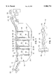
- FIG. 1 is a schematic diagram illustrating an aeration system with a plurality of submerged air diffusers and associated inflatable buoyant members each arranged in a different manner in accordance with the invention
- FIG. 2 is a schematic side view illustrating one of the diffusers of FIG. 1 after being raised to the surface of the water by inflated inflatable buoyant members;
- wastewater 10 in a basin 12 having a bottom surface 14 is aerated by one or more aeration lines consisting of a flexible aeration pipe 16 and a plurality of submerged aeration diffuser arrangements 18.
- the diffuser arrangements 18 are suspended near the bottom surface 14 of the basin by downcomers 20 connecting the diffusers to the flexible pipe 16 and supplying the diffusers with air under pressure from the pipe 16 for diffusion into the wastewater 10.
- the flexible pipe 16 is tethered by a cable 22 anchored by supports 24 at opposite sides of the basin with sufficient slack to permit the pipe 16 and the suspended diffuser arrangements 18 to sweep back and forth across the basin to a predetermined extent as air is ejected from them.
- Air is supplied to the pipe 16 and the diffuser arrangements 18 from an air supply 26 connected to the pipe through a control valve 28.
- each diffuser arrangement includes at least one inflatable buoyant member connected to an air pressure tube 32 which extends to the surface of the liquid in the basin.
- the inflatable buoyant members for the left diffuser arrangement 18 as seen in FIG. 1 are two bladders 30, located at opposite ends of the diffuser arrangement, which extend horizontally along the width of the diffuser arrangements.
- the air pressure tube 32 from each of the bladders 30 terminates in a valve 34 supported on the air line 16 through which compressed air may be supplied to the associated bladder 30 either from the pipe 16.
- air may be supplied to the air pressure tube from a portable compressed air supply such as a compressor in a boat or a compressed air container, in which case the valve 34 may be like an automobile tire valve.
- the inflated volume of both bladders 30 is sufficient to overcome the weight of the diffuser arrangement 18 and associated downcomers 20 and any attached ballast so that, when the bladders 30 are inflated, the diffuser arrangement will automatically rise to the surface of the liquid in the basin and assume a horizontal orientation with respect to the air pipe 16 as illustrated in FIG. 2.
- each diffuser arrangement has two bladders mounted at opposite ends as illustrated in FIG. 1 to facilitate uniform support of the diffuser arrangement at the surface of the water.
- the bladders 20 may be deflated by opening the valves 34, permitting the diffuser arrangement 18 to return to its submerged orientation.
- a single valve 34 may be connected to both of the inflatable buoyant members associated with each diffuser.
- an inflatable bladder 36 is affixed to the lower end of each of the downcomers 20 and each of the air pressure tubes 32 leading from the inflatable bladders 36 is connected to a valve 38 by which compressed air in a compressed air supply tube 40 extending along the flexible pipe 16 may be selectively introduced into the tubes 32 leading to the bladders 36.
- the compressed air supply tube 40 extends along the flexible pipe 16 to the shore of the basin 12 where it is connected through a valve 42 to the air supply 26 or, alternatively, to a separate pump 44 which is activated only when the diffusers 18 are to be serviced.
- the pump 44 When the pump 44 is turned on, the air pressure in the line 40 is maintained at a high level and, by selectively opening the valves 38 associated with individual diffuser arrangements 18, any one of the diffuser arrangements may be raised to the surface of the water as desired.
- valves 38 are also arranged to release air from the bladders 36 upon completion of the servicing operation so as to permit the bladders 34 to be deflated and the associated diffuser arrangement to return to its submerged position near the bottom of the basin.
- a single valve 38 may be used to supply compressed air to both of the inflatable buoyant members 36 or to release air from them.
- the attachment of inflatable bladders to the downcomers is especially useful when the diffuser arrangement 18 consists of only a single diffuser element rather than a series of elements in side-by-side relation as shown in FIG. 2.
- each inflatable buoyant member is a canister 46 mounted at the lower end of each downcomer 20.
- Each canister 46 is arranged, for example with an opening in the bottom, to permit displacement of water within the canister in response to air applied under pressure to the interior of the canister by adjusting the valves 34.
- the maximum volume of the canisters is selected so that they have sufficient buoyancy to raise the diffuser arrangement 18 to the surface of the water.
- the diffuser arrangement 18 consists of several tubular diffuser elements in side-by-side relation.
- the diffuser arrangement 18 could consist of a single tubular diffuser element or it could be a flat panel diffuser of the type described in the Strunc et al. Patent No. 5,192,467, the disclosure of which is incorporated by reference herein.
- the diffuser arrangements 18 need not be suspended above the bottom 14 of the basin but may instead rest on the bottom in a stationary condition.
- the air pressure supply line need not extend along the surface of the water if an appropriate valve control arrangement is provided at the shore of the basin.
Abstract
Description
Claims (10)
Priority Applications (1)
| Application Number | Priority Date | Filing Date | Title |
|---|---|---|---|
| US08/859,637 US5906774A (en) | 1997-05-20 | 1997-05-20 | Submerged diffuser lifting arrangement |
Applications Claiming Priority (1)
| Application Number | Priority Date | Filing Date | Title |
|---|---|---|---|
| US08/859,637 US5906774A (en) | 1997-05-20 | 1997-05-20 | Submerged diffuser lifting arrangement |
Publications (1)
| Publication Number | Publication Date |
|---|---|
| US5906774A true US5906774A (en) | 1999-05-25 |
Family
ID=25331388
Family Applications (1)
| Application Number | Title | Priority Date | Filing Date |
|---|---|---|---|
| US08/859,637 Expired - Lifetime US5906774A (en) | 1997-05-20 | 1997-05-20 | Submerged diffuser lifting arrangement |
Country Status (1)
| Country | Link |
|---|---|
| US (1) | US5906774A (en) |
Cited By (15)
| Publication number | Priority date | Publication date | Assignee | Title |
|---|---|---|---|---|
| US6029955A (en) * | 1998-05-23 | 2000-02-29 | Drie; Gerhardt Van | Counterbalanced dual submarine-type liquid mixer pairs |
| US6050550A (en) * | 1998-07-09 | 2000-04-18 | Burgess; Harry L. | Apparatus for aeration and bottom agitation for aqua-culture systems |
| US6708957B2 (en) | 1998-10-09 | 2004-03-23 | Zenon Environmental Inc. | Moving aerator for immersed membranes |
| US20050087894A1 (en) * | 2003-09-15 | 2005-04-28 | Campion William R. | Method and apparatus for aerating a surface layer in a stratified liquid body |
| US20060065595A1 (en) * | 2005-05-11 | 2006-03-30 | Thomas Menke | Waste effluent treatment system and process |
| US20080083659A1 (en) * | 2006-10-10 | 2008-04-10 | Envirolytic Technologies, Llc | Systems and methods of separating manure from a manure and bedding mixture |
| US20080224337A1 (en) * | 2007-03-13 | 2008-09-18 | Tharp Charles E | Diffuser assembly with buoyancy vessel |
| DE102007033483A1 (en) | 2007-07-18 | 2009-01-22 | Bioworks Verfahrenstechnik Gmbh | aerators |
| WO2009010204A1 (en) | 2007-07-18 | 2009-01-22 | Bioworks Verfahrenstechnik Gmbh | Method for stirring and/or aerating fluids, particularly sewage, particularly using a floodable aerator |
| US20090096117A1 (en) * | 2007-10-16 | 2009-04-16 | Tharp Charles E | Retrievable diffuser module with truss construction |
| DE102008021649A1 (en) | 2008-04-30 | 2009-11-05 | Bioworks Verfahrenstechnik Gmbh | Method for stirring and/or aerating fluids such as sewage, comprises cyclically aerating the fluid by immersed aerator for predetermined first period of time using aeration device, and then stirring the fluid for second period of time |
| US20110272831A1 (en) * | 2010-05-04 | 2011-11-10 | Robert Noel Pearson | Wastewater treatment system |
| US8740194B1 (en) * | 2013-11-12 | 2014-06-03 | Bader Shafaqa Alenzi | Buoyant aerator array with remote air supply |
| US10105659B2 (en) * | 2013-03-15 | 2018-10-23 | Claudius Jaeger | Dual control lateral air manifold assembly |
| US20210339173A1 (en) * | 2018-10-10 | 2021-11-04 | Roberts Marketing De, Inc. | Devices and methods for moving, removing and/or installing one or more components of a treatment unit |
Citations (7)
| Publication number | Priority date | Publication date | Assignee | Title |
|---|---|---|---|---|
| US4235720A (en) * | 1978-07-10 | 1980-11-25 | Hanshin Engineering Co., Ltd. | Underwater aerator |
| US4287062A (en) * | 1978-08-09 | 1981-09-01 | Nordenskjoeld Reinhart Von | Apparatus for biological purification of sewage |
| US4797212A (en) * | 1986-06-13 | 1989-01-10 | Nordenskjoeld Reinhart Von | Biological purification of waste waters |
| US5089179A (en) * | 1990-01-17 | 1992-02-18 | Nordenskjoeld Reinhart Von | Floating aerator arrangement |
| US5133876A (en) * | 1990-12-12 | 1992-07-28 | Environmental Dynamics, Inc. | Method and apparatus for aerating wastewater using sequential aeration of different zones |
| US5192467A (en) * | 1992-07-02 | 1993-03-09 | Parkson Corporation | Aeration panel structure |
| US5316671A (en) * | 1993-01-21 | 1994-05-31 | Murphy D Thomas | Submersible aeration train and aeration apparatus for biological purification of sewage |
-
1997
- 1997-05-20 US US08/859,637 patent/US5906774A/en not_active Expired - Lifetime
Patent Citations (7)
| Publication number | Priority date | Publication date | Assignee | Title |
|---|---|---|---|---|
| US4235720A (en) * | 1978-07-10 | 1980-11-25 | Hanshin Engineering Co., Ltd. | Underwater aerator |
| US4287062A (en) * | 1978-08-09 | 1981-09-01 | Nordenskjoeld Reinhart Von | Apparatus for biological purification of sewage |
| US4797212A (en) * | 1986-06-13 | 1989-01-10 | Nordenskjoeld Reinhart Von | Biological purification of waste waters |
| US5089179A (en) * | 1990-01-17 | 1992-02-18 | Nordenskjoeld Reinhart Von | Floating aerator arrangement |
| US5133876A (en) * | 1990-12-12 | 1992-07-28 | Environmental Dynamics, Inc. | Method and apparatus for aerating wastewater using sequential aeration of different zones |
| US5192467A (en) * | 1992-07-02 | 1993-03-09 | Parkson Corporation | Aeration panel structure |
| US5316671A (en) * | 1993-01-21 | 1994-05-31 | Murphy D Thomas | Submersible aeration train and aeration apparatus for biological purification of sewage |
Cited By (27)
| Publication number | Priority date | Publication date | Assignee | Title |
|---|---|---|---|---|
| US6029955A (en) * | 1998-05-23 | 2000-02-29 | Drie; Gerhardt Van | Counterbalanced dual submarine-type liquid mixer pairs |
| US6050550A (en) * | 1998-07-09 | 2000-04-18 | Burgess; Harry L. | Apparatus for aeration and bottom agitation for aqua-culture systems |
| US6708957B2 (en) | 1998-10-09 | 2004-03-23 | Zenon Environmental Inc. | Moving aerator for immersed membranes |
| US20050087894A1 (en) * | 2003-09-15 | 2005-04-28 | Campion William R. | Method and apparatus for aerating a surface layer in a stratified liquid body |
| US7267766B2 (en) * | 2003-09-15 | 2007-09-11 | Pro-Act Microbial, Inc. | Method and apparatus for aerating a surface layer in a stratified liquid body |
| US20060027496A1 (en) * | 2004-06-10 | 2006-02-09 | Campion William R | Microbial manure treatment system |
| US20060065595A1 (en) * | 2005-05-11 | 2006-03-30 | Thomas Menke | Waste effluent treatment system and process |
| US7445707B2 (en) | 2005-05-11 | 2008-11-04 | Envirolytic Technologies, Llc | Waste effluent treatment system |
| US7552827B2 (en) | 2006-10-10 | 2009-06-30 | Envirolytic Technologies, Llc | Systems and methods of separating manure from a manure and bedding mixture |
| US20080083659A1 (en) * | 2006-10-10 | 2008-04-10 | Envirolytic Technologies, Llc | Systems and methods of separating manure from a manure and bedding mixture |
| US8011643B2 (en) | 2007-03-13 | 2011-09-06 | Environmental Dynamics, Inc. | Diffuser assembly with buoyancy vessel |
| US20110215042A1 (en) * | 2007-03-13 | 2011-09-08 | Tharp Charles E | Diffuser assembly with buoyancy vessel |
| US8246018B2 (en) | 2007-03-13 | 2012-08-21 | Environmental Dynamics International, Inc. | Diffuser assembly with buoyancy vessel |
| WO2008144098A3 (en) * | 2007-03-13 | 2009-01-29 | Environmental Dynamics Inc | Diffuser assembly with buoyancy vessel |
| US20080224337A1 (en) * | 2007-03-13 | 2008-09-18 | Tharp Charles E | Diffuser assembly with buoyancy vessel |
| WO2008144098A2 (en) * | 2007-03-13 | 2008-11-27 | Environmental Dynamics, Inc. | Diffuser assembly with buoyancy vessel |
| US20100181263A1 (en) * | 2007-07-18 | 2010-07-22 | Bioworks Verfahrenstechnik Gmbh | Method for stirring and/or aerating fluids, particularly sewage, particularly using a floodable aerator |
| DE102007033483A1 (en) | 2007-07-18 | 2009-01-22 | Bioworks Verfahrenstechnik Gmbh | aerators |
| US8241497B2 (en) | 2007-07-18 | 2012-08-14 | Bioworks Verfahrenstechnik Gmbh | Method for stirring and/or aerating fluids, particularly sewage, particularly using a floodable aerator |
| WO2009010204A1 (en) | 2007-07-18 | 2009-01-22 | Bioworks Verfahrenstechnik Gmbh | Method for stirring and/or aerating fluids, particularly sewage, particularly using a floodable aerator |
| US20090096117A1 (en) * | 2007-10-16 | 2009-04-16 | Tharp Charles E | Retrievable diffuser module with truss construction |
| US8016272B2 (en) * | 2007-10-16 | 2011-09-13 | Environmental Dynamics, Inc. | Retrievable diffuser module with truss construction |
| DE102008021649A1 (en) | 2008-04-30 | 2009-11-05 | Bioworks Verfahrenstechnik Gmbh | Method for stirring and/or aerating fluids such as sewage, comprises cyclically aerating the fluid by immersed aerator for predetermined first period of time using aeration device, and then stirring the fluid for second period of time |
| US20110272831A1 (en) * | 2010-05-04 | 2011-11-10 | Robert Noel Pearson | Wastewater treatment system |
| US10105659B2 (en) * | 2013-03-15 | 2018-10-23 | Claudius Jaeger | Dual control lateral air manifold assembly |
| US8740194B1 (en) * | 2013-11-12 | 2014-06-03 | Bader Shafaqa Alenzi | Buoyant aerator array with remote air supply |
| US20210339173A1 (en) * | 2018-10-10 | 2021-11-04 | Roberts Marketing De, Inc. | Devices and methods for moving, removing and/or installing one or more components of a treatment unit |
Similar Documents
| Publication | Publication Date | Title |
|---|---|---|
| US5906774A (en) | Submerged diffuser lifting arrangement | |
| US5587114A (en) | Aeration system employing retrievable aeration modules | |
| US5860379A (en) | Inflatable floating boat lift | |
| CN101965222B (en) | Aeration device for the introduction of gas bubbles into a liquid medium | |
| US7421963B1 (en) | Watercraft dry storage and storage method | |
| US6745714B1 (en) | Control for variable buoyancy floating dock | |
| US8246018B2 (en) | Diffuser assembly with buoyancy vessel | |
| US4216091A (en) | Water aerator | |
| US20020011200A1 (en) | Float switch activation assembly | |
| US20010015163A1 (en) | Combined dry dock and boat launching apparatus | |
| US4507093A (en) | Buoy device for automatic raising of submerged objects | |
| US6260831B1 (en) | Apparatus for aerating water with fine bubbles | |
| KR950700107A (en) | Decanting apparatus | |
| US5690864A (en) | Retrievable aeration system | |
| CA2334873C (en) | Automatically inflatable boat | |
| US5690047A (en) | Buoyant anchorage mechanism | |
| US20020113013A1 (en) | Aeration system for wastewater | |
| US20110203983A1 (en) | Treatment Device and Treatment Bag | |
| US8016272B2 (en) | Retrievable diffuser module with truss construction | |
| US7096809B1 (en) | Watercraft dry storage and storage method | |
| WO1994023994A1 (en) | Floating dock | |
| JP4068586B2 (en) | Device for lifting and lowering diffused gas in an aeration tank | |
| AU674273B2 (en) | Flotation device | |
| JP2004501658A (en) | Open sea fish farming equipment | |
| CN215102308U (en) | Aeration device |
Legal Events
| Date | Code | Title | Description |
|---|---|---|---|
| AS | Assignment |
Owner name: PARKSON CORPORATION, FLORIDA Free format text: ASSIGNMENT OF ASSIGNORS INTEREST;ASSIGNOR:LOY, DANIEL E.;REEL/FRAME:008572/0320 Effective date: 19970519 |
|
| STCF | Information on status: patent grant |
Free format text: PATENTED CASE |
|
| FEPP | Fee payment procedure |
Free format text: PAYOR NUMBER ASSIGNED (ORIGINAL EVENT CODE: ASPN); ENTITY STATUS OF PATENT OWNER: LARGE ENTITY |
|
| FPAY | Fee payment |
Year of fee payment: 4 |
|
| REMI | Maintenance fee reminder mailed | ||
| FPAY | Fee payment |
Year of fee payment: 8 |
|
| SULP | Surcharge for late payment |
Year of fee payment: 7 |
|
| FEPP | Fee payment procedure |
Free format text: PAYER NUMBER DE-ASSIGNED (ORIGINAL EVENT CODE: RMPN); ENTITY STATUS OF PATENT OWNER: LARGE ENTITY |
|
| FPAY | Fee payment |
Year of fee payment: 12 |