US5911406A - Liquid dispensing and item storage system with orally activated valve - Google Patents

Liquid dispensing and item storage system with orally activated valve Download PDF

Info

Publication number
US5911406A
US5911406A US08/529,080 US52908095A US5911406A US 5911406 A US5911406 A US 5911406A US 52908095 A US52908095 A US 52908095A US 5911406 A US5911406 A US 5911406A
Authority
US
United States
Prior art keywords
valve
liquid
user
plunger
mouth
Prior art date
Legal status (The legal status is an assumption and is not a legal conclusion. Google has not performed a legal analysis and makes no representation as to the accuracy of the status listed.)
Expired - Fee Related
Application number
US08/529,080
Inventor
Carl Winefordner
Frank Hermansen
Jean-Claude Olivieri
Current Assignee (The listed assignees may be inaccurate. Google has not performed a legal analysis and makes no representation or warranty as to the accuracy of the list.)
Bell Sports Inc
Original Assignee
Winefordner; Carl
Hermansen; Frank
Olivieri; Jean-Claude
Priority date (The priority date is an assumption and is not a legal conclusion. Google has not performed a legal analysis and makes no representation as to the accuracy of the date listed.)
Filing date
Publication date
Application filed by Winefordner; Carl, Hermansen; Frank, Olivieri; Jean-Claude filed Critical Winefordner; Carl
Priority to US08/529,080 priority Critical patent/US5911406A/en
Application granted granted Critical
Publication of US5911406A publication Critical patent/US5911406A/en
Assigned to BELL SPORTS, INC. reassignment BELL SPORTS, INC. ASSIGNMENT OF ASSIGNORS INTEREST (SEE DOCUMENT FOR DETAILS). Assignors: HERMANSEN, FRANK, OLIVIERI, JEAN-CLAUDE, WINEFORDNER, CARL
Assigned to FLEET NATIONAL BANK AS ADMINISTRATIVE AGENT reassignment FLEET NATIONAL BANK AS ADMINISTRATIVE AGENT FIRST SUPPLEMENTAL PATENT COLLATERAL ASSIGNMENT AND SECURITY AGREEMENT, ATTACHED HERETO AS EXHIBIT 1. Assignors: BELL SPORTS, INC
Anticipated expiration legal-status Critical
Expired - Fee Related legal-status Critical Current

Links

Images

Classifications

    • AHUMAN NECESSITIES
    • A45HAND OR TRAVELLING ARTICLES
    • A45FTRAVELLING OR CAMP EQUIPMENT: SACKS OR PACKS CARRIED ON THE BODY
    • A45F3/00Travelling or camp articles; Sacks or packs carried on the body
    • A45F3/16Water-bottles; Mess-tins; Cups

Definitions

  • the rate at which bodily liquids are released into the atmosphere increases with ambient temperature, humidity, wind velocity, wearing apparel, and physical exersion. While exercising vigorously, an athlete loses an average of one liter of bodily liquid per hour which can lead to dehydration if not replaced by ingested liquid. It is preferred that liquids be ingested at substantially the same rate at which they are dissipated in order to ensure good health, maximize physical performance and to avoid the dangers of heat prostration.
  • Some items to be carried may be valuable; others such as lip balm are small and difficult to find if not placed in a small identifiable pocket, while others such as a jacket are bulky. It would be advantageous for a liquid dispensing system to have small pockets to store certain items and at least one large pocket for larger items and yet this usually leads to a bulky and cluttered arragement. It would also be advantageous for secure storage of valuable items. Small pockets incorporated within a large pocket, would accomplish these advantages by providing space for small and large items in a neat, compact arrangement, while incorporating multiple closures for security.
  • the weight of the liquid dispensing and storage system is of primary importance.
  • Existing liquid dispensing systems utilizing multi-bag construction are relatively heavy. It would be advantageous to have a liquid dispensing and storage system that is integrated such that it is one complete unit reducing construction material usage for weight reduction while maintaining the benefits of insulation and storage.
  • orienting holders on existing liquid dispensing systems with storage capabilities are either fixed in place on the shoulder strap, making them unadjustable, or utilize a clip which requires the use of both hands in order to fix in place or adjust such systems. It would be desirable for a liquid dispensing system to have orienting holders which are easily adjustable to different positions along the shoulder strap utilizing only one hand.
  • Athletes must ingest liquids while breathing rapidly and deeply. It would be advantageous to be able to frequently swallow small amounts of liquid intermittently between breaths, allowing maximum liquid intake without sacrificing oxygen intake. It would be desirable to have an orally activated valve device that can be easily held in the teeth without activating the valve in order to be able to breathe heavily between instances of liquid ingestion without liquid dripping from the valve. This would allow repetitive liquid intake and breathing without unwanted liquid flow interfering with breathing.
  • a drinking device When the mouth is in a sucking configuration, the tongue naturally thrusts forward to prevent the object from entering too far into the mouth. It would be desirable for a drinking device to have an orally activated valve that utilizes the natural thrusting of the tongue to depress an activating member on the front of the device.
  • a valve device which easily dislodges from the flexible tubing could be ingested into the lungs or passageways associated with the lungs of hyperventilating athletes such as runners or cyclists.
  • a unitary resilient valve device as described in the prior art for example, easily dislodges from the flexible tubing because the material used cannot be both soft and resilient enough to function as a bite valve, yet be stiff enough to resist accidental dislodgment. It would be desirable for a valve device for oral use to be securely connected to the flexible tubing in order to avoid the possibility of the valve device being ingested by the user.
  • the present invention comprises a novel liquid dispensing system with an orally activated valve device that integrates a collapsible container with straps for removably securing the system at a location on the back between the shoulders and integrates auxiliary expandable storage pockets.
  • the invention has an externally accessible fill port that is covered by a flexible flap which is held in place by shoulder straps and insulates the user from feeling the fill port cap against his or her back while wearing the system.
  • Flexible tubing is routed from an elbow attached to the collapsible container, then under an auxiliary pocket panel and out through a slot over either shoulder and is held conveniently near the user's mouth by an adjustable ring attached to the shoulder strap.
  • An embossed foam panel insulates the liquid and provides air channels to vent and dissipate body heat.
  • the present invention provides a liquid dispensing system with an orally activated valve device that avoids the aforementioned drawbacks of the prior art.
  • the orally activated valve of the present invention can be arranged to provide a simple pump system that can be manipulated by the mouth or hand to move liquid from one location to another.
  • This invention includes a novel device which is in the form of an elongated body member that provides a hollow structure having an open inlet end opposed to a closed outlet end.
  • a fluid supply chamber is formed between the inlet and outlet ends.
  • the open inlet end is connected to a length of tubing to supply fluid flow from a suitable container to the supply chamber, while the closed outlet end provides a valve plunger closure which can be depressed or deformed into an opened configuration to enable fluid flow to occur therethrough.
  • this invention relates to a valve apparatus of a size and configuration to be comfortably received within a person's mouth for use in a system for delivering liquid from a container to the valve apparatus located in a person's mouth.
  • the valve is in the form of an elongated body member that forms a hollow structure having an open inlet and opposed a closed outlet end, a fluid supply chamber being formed between the inlet and outlet ends.
  • the open inlet end can be connected to a length of tubing to supply fluid flow from the container to the supply chamber, while the close outlet end provides a valve plunger closure member that normally precludes fluid flow therethrough, and which can be depressed with one's tongue or teeth into an opened configuration to enable fluid flow to occur therethrough and into a person's mouth.
  • the container provides a liquid supply and is connected to the tubing end opposed to the valve such that the tubing and container provide a fluid source for the supply chamber of the valve.
  • the valve body is placed in one's mouth so that the valve plunger can be depressed by one's tongue or teeth and thereby open the valve in proportion to the force exerted thereagainst and thereby enable flow to occur from the supply chamber.
  • the liquid can be metered into one's mouth whenever desired by depressing the valve plunger thereby opening the valve and allowing liquid to flow into one's mouth.
  • the liquid can be metered into one's mouth whenever desired by depressing the valve plunger to open the valve and sucking at various vacuum levels causing the liquid to flow into one's mouth.
  • valve body After the person is finished drinking, they can, if desired, then drop the valve body from their mouth or "spit" it out and liquid will not drip from the valve outlet unless the valve body is purposely and vigorously shaken.
  • valve body and valve plunger enables the apparatus to be held in any position without regard for orientation in one's mouth and thereby meter fluid into the body with very little conscious effort.
  • An object of the present invention is the provision of a collapsible liquid container that integrates straps for removably securing the container at a location between the shoulders of the person and also integrates auxiliary expandable storage pockets.
  • a primary object of the present invention is the provision of a valve apparatus that precludes flow therethrough until the valve plunger thereof is depressed whereupon flow can occur through a closure member thereof.
  • Another object of the present invention is the provision of a collapsible liquid container that integrates auxiliary expandable storage pockets within a main expandable storage pocket.
  • Another object of the present invention is the provision of a collapsible liquid container that integrates auxiliary expandable storage pockets within a main expandable storage pocket that collapse into a relatively streamlined system when empty.
  • Another object of the present invention is the provision of a collapsible liquid container that integrates auxiliary expandable storage pockets and straps for removably securing the container at a location between the shoulders and that has flexible tubing routed from the collapsible container through orienting holders along the shoulder straps in order to conveniently hold the apparatus near the user's mouth without the need to remove the tube from the orienting holders in order to fill the collapsible container with liquid.
  • Another object of the present invention is the provision of a collapsible liquid container that integrates auxiliary expandable storage pockets and straps for removably securing the container at a location between the shoulders of the user and that has flexible tubing routed from the collapsible container through orienting holders along the shoulder straps and wherein the orienting holders can be easily moved along the straps with one hand in order to adjust the location according to personal preference.
  • Another object of the present invention is the provision of a collapsible liquid container that employs an embossed foam panel that insulates the liquid and provides air channels to vent and dissipate body heat.
  • Another object of the present invention is the provision of a collapsible liquid container that integrates auxiliary expandable storage pockets and has an externally accessible fill port for filling the collapsible container with liquid.
  • Another object of the present invention is the provision of a collapsible liquid container that integrates auxiliary expandable storage pockets and that has an externally accessible fill port covered by a flexible flap which is held in place by the shoulder straps.
  • Another object of the present invention is the provision of a collapsible liquid container that utilizes shoulder straps for removably securing the container at a location between the user's shoulders and auxiliary expandable storage pockets and has an externally accessible fill port covered by a flexible flap which is held in place by the shoulder straps in such a way that the fill port is held separated from the user's body through the flap because the fill port is held distant from the flap when the straps are pulled tight.
  • Another object of the present invention is the provision of a collapsible liquid container that has a fill port with multiple support legs on the inner surface such that the opposite flexible wall of the container is held slightly distant from the fill port so that liquid can flow less impeded into the container during the filling operation.
  • Another object of the present invention is the provision of a valve device adapted to be placed into one's mouth such that one can depress a valve plunger with one's tongue or teeth and open a closure member thereof through which fluid can flow into a person's mouth.
  • a further object of the present invention is the provision of a supply of liquid carried on one's body and connected to a valve device that can be conveniently and comfortably held within one's mouth and when the valve device is held in one's mouth, liquid flows from the supply into the person's mouth in proportion to the force exerted against the valve plunger of the valve device.
  • Another object of the present invention is to provide a valve device having an end wall that connects a supply chamber to ambient and a valve plunger located through the end wall with the valve device having a configuration whereby the force exerted against the valve plunger of the valve device determines the rate of flow through the valve body.
  • An additional object of this invention is to provide a valve device having a valve plunger located through an end wall thereof wherein the pressure exerted against the valve plunger of the valve device determines the movement of a seal away from a sealing surface and the flow rate therethrough.
  • Another object of this invention is the provision of a valve in the form of an elongated body member that forms a hollow structure having an open inlet end opposed to a closed outlet end, with there being a fluid supply chamber formed between the inlet and outlet ends, and the open end is connected to the end of a length of tubing in order to supply fluid flow to the supply chamber, while the closed end is provided with a closure member that normally precludes fluid flow therethrough and which can be manipulated by the tongue and/or teeth into an opened configuration to enable fluid flow to occur therethrough.
  • Another object of this invention is to have an orally activated valve device that can be held in one's mouth and in particular one's teeth without activating the valve to allow one to breathe heavily between liquid intake cycles.
  • Another object of this invention is to have a valve device that makes use of the natural sucking phenomenon whereby one tends to thrust one's tongue forward when sucking on an object.
  • Another object of this invention is to have an orally activated valve device that does not drip liquid from the valve outlet after closure occurs.
  • Another object of this invention is to provide a means to securely connect a valve device to tubing and yet still allow the valve device to be purposely disconnected when desired for cleaning or replacement.
  • Still another object of the present invention is to provide a round, orally-activated valve device that can be held in any position without regard for rotational orientation in one's mouth.
  • FIG. 1 is a broken, side elevational view of a bicyclist, with the present invention being diagrammatically illustrated therewith;
  • FIG. 2 is a broken, side elevational view of a hiker, with the present invention being diagrammatically illustrated therewith;
  • FIG. 3 is a view of the top and side of the drinking system
  • FIG. 4 is longitudinal, cross-sectional view taken along lines 5--5 in FIG. 3;
  • FIG. 5 is a view of a person orally activating the valve apparatus with their tongue
  • FIG. 6 is a view of a person orally activating the valve apparatus with their teeth
  • FIG. 7 is a view of a person orally activating the valve apparatus with their teeth in a different manner than in FIG. 6;
  • FIG. 8 is a cross-sectional view taken along lines 6--6 in FIG. 3;
  • FIG. 9 is a longitudinal view with the valve in the normally closed position
  • FIG. 10 is a longitudinal, cross-sectional view taken along lines 3--3 in FIG. 12 with the valve in the normally close position;
  • FIG. 11 is another longitudinal, cross-sectional view taken along lines 3--3 in FIG. 12 with the valve being in the open position;
  • FIG. 12 is an end view of the apparatus disclosed in FIGS. 9, 10 and 11 taken along lines 4--4 in FIG. 9.
  • FIG. 1 there is shown a bicycle 144 being ridden by a rider or bicyclist 146.
  • the bicyclist has a pack or drinking system 140, made in accordance with the present invention, attached to his back and elevated higher than his mouth 148.
  • a flexible tube 54 leads from the pack 140 to the bicyclist's mouth.
  • FIG. 2 there is shown a hiker 152 with the pack 140, made in accordance with the present invention, attached to his back and positioned below his mouth 154.
  • a flexible tube 54 leads from the pack 140 to the hiker's mouth.
  • the pack 140 is partially filled with liquid and/or carry items. Items are stored within the drinking system by opening the zipper 120 in the main pocket upper panel 72 and placing the items inside the expandable area 66.
  • a folded gusset panel 122 connects the main pocket upper panel 72 to the rest of the system and allows storage area expansion while allowing the main pocket upper panel 72 to lay substantially flat to the panels beneath when the storage area 66 is empty.
  • Upper straps 92 connect to a fill port flap 98 through slots in the strap guides 86 to ladder lock buckles 56.
  • Lower straps 93 attach to the end of the system 134 and are routed through the ladder lock buckles 56.
  • Tubing 54 exits the bag system through either one of two slot openings 80 in the main pocket upper panel 72 depending on which side the user prefers.
  • the tubing then routes through a tubing guide 84.
  • the tubing guide 84 can be moved to support the tubing 54 at different positions, along the strap 92, depending on the user preference.
  • the tubing 54 is connected to the orally activated valve apparatus 90.
  • the system comprises an insulating panel 118, a lower bladder panel 114, an upper bladder panel 60, a flexible tube 54, an orally activated valve apparatus 90, straps 92, lower pocket panel 78, upper auxiliary pocket panel and closure flap 68 and 76 respectively, and a main pocket upper panel 72.
  • Liquid is stored within the chamber 106 that is formed of lower bladder panel 114 and upper bladder panel 60.
  • Bladder panels 114 and 60 are connected by heat sealing such as by radio frequency welding or gluing.
  • Bladder panels 114 and 60 are made of materials such as urethane coated nylon packcloth that can seal liquid within.
  • a fill port cap 100 seals against a fill port 94 which is sealed to the lower bladder panel 114 by heat sealing in the same manner as the bladder panels.
  • upper surfaces 96 of the legs 102 of the fill port 94 prevent the inner surface 104 of the upper bladder panel 60 from effectively sealing against the port 94 and thus allow liquid to easily enter the chamber 106 relatively unimpeded and without special care required to orient surface 104 away from fill port 94.
  • Tubing 54 is connected to the elbow 62 at area 64 by glue, press fit, or by adding a barbed hollow male/male fitting (not shown) between the elbow 62 and the tubing 54.
  • the tubing 54 is routed between the upper bladder panel 60 and the lower pocket panel 78 and exits the system through a large opening 156 in the lower pocket panel 78 and then through either of two openings 80 depending on user preference, in the main pocket upper panel 72 in line with a shoulder strap 92, as best shown in FIG. 3.
  • the tubing is then routed through a tubing guide 84.
  • Tubing guide 84 can be moved to support the tubing 54 at different positions along the strap 92 depending on user preference.
  • the tubing 54 is connected to the orally activated
  • the main expandable storage area 66 is created by the upper bladder panel 60, auxiliary pocket panel 68 and closure flap 76, two gusset panels 122 as best shown in FIG. 8, and the main pocket upper panel 72.
  • a zipper 120 provides access to and closure of area 66 as shown in FIG. 3.
  • An expandable storage area 70 is created by the auxiliary pocket panel 68, closure flap 76, and the lower auxiliary pocket panel 78.
  • Auxiliary panel 68 is folded to allow expansion.
  • the closure flap 76 is secured to the auxiliary pocket panel 68 with a hook and loop fastener 74.
  • the closure flap 76 overlaps the auxiliary pocket panel 68 so that the closure flap 76 can still be fastened to the auxiliary pocket panel 68 with the hook and loop fastener 74 even when area 70 is filled to capacity to a fully expanded state.
  • An insulating panel 118 is attached to the lower bladder panel 114 from the end 134 of the system to the hinge line 136 and insulates the liquid within a chamber 106 from ambient and the user's body heat.
  • the insulating panel is made of flexible foam laminated on both sides with an abrasion resistant material such as nylon cloth and is embossed to form channels 110 and ribs 108.
  • the surfaces 112 of ribs 108 are in contact with the user's body at a location between the shoulders.
  • the embossed channels 110 allow air to vent between the drinking system and the user's body.
  • the fill port flap 98 which is a continuation of insulating panel 118, hinges along line 136 in order to expose the fill port 94 and fill port cap 100 for filling chamber 106 with liquid. Straps 92 attach to the fill port flap 98 at area 158 and are routed through the strap guide 86 slots 88.
  • the length of the lower bladder panel 114 from hinge point 136 to the end of strap guide 86, which contains the fill port 94, is slightly longer than the fill port flap 98 from hinge point 136 to area 158.
  • the fill port flap 98 When the straps 92 are pulled tight, such as when removably securing the container at a location between the shoulders of the user, the fill port flap 98 is relatively straight against the user's body and the fill port mounted area of the lower bladder panel 114 is forced to curve holding the fill port 94 slightly separated from the backside of the fill port flap panel 98. This prevents uncomfortable point pressure that the fill port cap 100 might otherwise exert against the user's body.
  • FIG. 5 shows a person orally activating the valve apparatus with his or her tongue.
  • the user's upper and lower lips, 130 and 132 respectively are shown distant from the valve apparatus in order to show the activation more clearly.
  • the user is holding the valve apparatus 90 by biting gently with his or her upper and lower teeth, 124 and 126 respectively, on surface 44.
  • the user would close his or her lips, 130 and 132, around surface 42 or 44 of the valve apparatus 90, and push his or her tongue 128 against the valve plunger 26.
  • Surface 16 of the ring cap 28 prevents the valve apparatus 90 from being pushed out of one's mouth without the need to bite hard on surface 44. Oral suction also generally helps retain the valve apparatus while ingesting the liquid.
  • valve apparatus 90 If the liquid container is at a location higher than the valve apparatus 90, such as in FIG. 1, then hydrostatic pressure will cause liquid to flow without the need for suction. If the liquid container is at a location lower then the valve apparatus 90, such as in FIG. 2, then the user will need to create suction with their mouth in order to ingest the liquid. The person can also hold the valve apparatus 90 between his or her teeth without depressing the valve plunger 26 so that he or she can breathe without activating the valve apparatus.
  • FIG. 6 shows a person orally activating the valve apparatus with his or her teeth.
  • the user's upper and lower lips, 130 and 132 respectively, are shown distant from the valve apparatus in order to show the activation more clearly.
  • the user is holding the valve apparatus 90 with his or her upper teeth 124 against surface 16 of the ring cap 28 and his or her lower teeth 126 against valve plunger 26.
  • the user would close his or her lips, 130 and 132, around surface 42 or 44 of the valve apparatus 90, and bite against the valve plunger 26.
  • Surface 16 of the ring cap 28 and lip pressure against surfaces 42, 12, 44 and/or 16 prevent the valve apparatus 90 from being pushed out of one's mouth. Oral suction also generally helps retain the valve apparatus while ingesting the liquid.
  • the liquid container is at a location higher than the valve apparatus 90, then hydrostatic pressure will cause liquid to flow without the need for suction. If the liquid container is at a location lower then the valve apparatus 90, then the user will need to create suction with his or her mouth in order to ingest the liquid.
  • FIG. 7 shows a person orally activating the valve apparatus with his or her teeth in a manner different than in FIG. 6.
  • the user's upper and lower lips, 130 and 132 respectively, are shown distant from the valve apparatus in order to show the activation more clearly.
  • the user is holding the valve apparatus 90 with his or her lower teeth 126 against surface 16 of the ring cap 28 and his or her upper teeth 124 against valve plunger 26.
  • the user would close his or her lips, 130 and 132, around surface 42 or 44 of the valve apparatus 90, and bite against the valve plunger 26.
  • Surface 16 of the ring cap 28 and lip pressure against surfaces 42, 12, 44 and/or 16 prevent the valve apparatus 90 from being pushed out of one's mouth.
  • Oral suction also generally helps retain the valve apparatus while ingesting the liquid. If the liquid container is at a location higher than the valve apparatus 90, then hydrostatic pressure will cause liquid to flow without the need for suction. If the liquid container is at a location lower then the valve apparatus 90, then the user will need to create suction with his or her mouth in order to ingest the liquid.
  • the valve shown is a cross-sectional view looking in the direction of lines 6--6 in FIG. 3.
  • Gusset panels 122 attach the upper bladder panel 60 to the main pocket upper panel 72. Because of the fold in gusset panel 122, the main pocket upper panel 72 is free to move away from the upper bladder panel 60 to accommodate stored items within the main pocket storage area 66 and the auxiliary pocket storage area 70.
  • folds 138 within the upper auxiliary pocket panel 68 act as gussets to expand when items are stored within area 70. Gussets 122 and folds 138 also freely collapse to provide a relatively streamlined system when area 66 and/or 70 are empty.
  • valve is shown in a longitudinal view in the normally closed position.
  • the user can hold the valve within his or her mouth by holding surfaces 42 and 44 between the teeth or lips.
  • Surfaces 12 and 16 prevent the valve from slipping out of the user's mouth without having to apply large force against surfaces 42 or 44.
  • the valve plunger 26 on surface 22 with his or her tongue or teeth By pushing against the valve plunger 26 on surface 22 with his or her tongue or teeth, the user orally opens the valve.
  • valve In FIG. 10, the valve is shown in a longitudinal, cross-sectional view in the normally closed position.
  • Flexible tubing 54 has been pushed onto the barbed portion of valve body 34 and is secured in place by the barb 10.
  • the angled surface 40 of the valve body 34 allows easy installation of the flexible tube 54 while the barb 10 prevents accidental separation and still allows purposeful separation for cleaning or replacement, if necessary.
  • the ring cap 28 is bonded to the valve body 34 at attachment area 18 by glue, ultrasonic welding, screw threads, tight press fit or other appropriate means which both seals the parts together and prevents separation.
  • a valve plunger 26 Inside this ring cap 28 and valve body 34 there are a valve plunger 26, an O-ring 32, and a compression spring 38.
  • the O-ring 32 seals against surface 24 of the valve plunger 26 and is biased into a closed position against sealing surface 30 of the ring cap 28 by the compression spring 38 and hydrostatic pressure that is present if the liquid container is higher than the valve apparatus 90.
  • the ends of compression spring 38 are held in position at one end by the valve body surface 50 and at the other end by the valve plunger surface 52.
  • valve is shown with enough force applied to the valve plunger 26 on surface 22 to overcome the force applied from the compression spring 38 and any hydrostatic pressure causing the valve plunger 26 to have moved such that the O-ring 32 is no longer in contact with the ring cap surface 30.
  • This plunger position connects the valve chamber 14 to ambient and allows liquid within the valve chamber 14 to flow down the tube, along the valve plunger ribs 36, around the O-ring 32 and out through the flow channel 20.
  • Each flow channel 20 is sufficiently small in cross-section to prevent liquid from dripping from the valve after valve closure occurs.
  • all of the areas within the valve assembly that the liquid passes through should be sized such that they are equal to or bigger than the flow area of the tube.
  • the valve plunger 26 is aligned to the spring 38 by the multiple ribs 36 of the valve plunger 26 close proximity to compression spring 38 internal diameter.
  • the compression spring 38 is aligned to the valve body 26 by the outer diameter of the compression spring 38 close proximity to the internal diameter of the valve body 34.
  • valve is shown in an end view.
  • the multiple surfaces 46 of the valve plunger 26 align the valve plunger 26 to the ring cap 28 while the flow channels 20 allow liquid to flow through with minimal restriction.
  • the total area between the valve plunger 26 and the ring cap 28 should be equal to or greater than the flow area of the tube 54 shown in FIG. 10.
  • the surface 22 of the valve plunger 26 is free of distortions and sharp areas that could cause discomfort against the user's tongue.
  • the valve plunger 26 is aligned to the ring cap 28 by alignment surface 46 close proximity to the ring cap 28 opening diameter 48.
  • the generally round shape of the ring cap 28, the valve plunger 26 and the valve body 34 allow use of the valve apparatus 90 without regard for rotational orientation.

Abstract

A combined liquid dispensing and item storage system with an orally activated valve. The system comprises a collapsible container for liquid that incorporates integrated auxiliary expandable storage pockets. The system is removably secured at a location on the back between the shoulders. An externally accessible fill port is covered by a flexible embossed foam panel held in place by shoulder straps and which panel protects against the discomfort of the fill port cap against the back, insulates the liquid, and provides air channels to vent and dissipate body heat. A length of flexible tubing for delivering the liquid is attached to the collapsible container, then routed through a slot in the auxiliary expandable storage pocket, over either shoulder, and held near the mouth by adjustable orienting holders attached to the shoulder straps. The orally activated valve is located at the end of the flexible tubing which delivers the liquid from the flexible tubing to the mouth. The valve device is in the form of an elongated hollow structure having an open inlet end opposed to a closed outlet end forming a fluid supply chamber between the open inlet and closed outlet end. The open inlet end is connected to the flexible tubing in order to obtain liquid from the collapsible container for the supply chamber. The closed outlet end embodies a spring biased valve plunger which can be depressed by tongue or teeth to move the valve plunger into an open configuration to enable liquid flow therethrough.

Description

BACKGROUND OF THE INVENTION
1. Field of the Invention
The rate at which bodily liquids are released into the atmosphere increases with ambient temperature, humidity, wind velocity, wearing apparel, and physical exersion. While exercising vigorously, an athlete loses an average of one liter of bodily liquid per hour which can lead to dehydration if not replaced by ingested liquid. It is preferred that liquids be ingested at substantially the same rate at which they are dissipated in order to ensure good health, maximize physical performance and to avoid the dangers of heat prostration.
While bicyclists, long distance runners, hikers, and other athletes require continuous replacement of bodily liquids, this is difficult to achieve because of the complexities involved in simultaneously drinking from a container while performing the athletic functions such as pedaling a bicycle or maintaining timing, rhythm and balance.
When performing certain outdoor activities such as bicycling or hiking, it is desirable to carry items such as sunscreen, an emergency medical kit, a jacket, identification, and tools as well as liquids. Depending on the duration and type of activity, the need for equipment varies. At certain times it may be that only liquids are desired. It would be desirable for a liquid dispensing system to be compact and streamline when carrying only liquids yet have the ability to expand to carry numerous miscellaneous items as needed.
Some items to be carried may be valuable; others such as lip balm are small and difficult to find if not placed in a small identifiable pocket, while others such as a jacket are bulky. It would be advantageous for a liquid dispensing system to have small pockets to store certain items and at least one large pocket for larger items and yet this usually leads to a bulky and cluttered arragement. It would also be advantageous for secure storage of valuable items. Small pockets incorporated within a large pocket, would accomplish these advantages by providing space for small and large items in a neat, compact arrangement, while incorporating multiple closures for security.
2. Prior Art
Existing liquid dispensing systems that use a collapsible container for holding liquid are constructed such that the collapsible container is independent of the insulating pouch which is independent of a storage pouch that incorporates pockets for storage. These systems are bulky, cumbersome, and expensive because they are, in essence, comprised of a bag within a bag within a bag. In order to fill the bladder with liquid, one must open the outer bag or bags and remove the bladder. The full bladder must then be pushed into the insulating pouch, a difficult and cumbersome task, especially if an additional outer storage bag is full of extraneous but necessary items. It would be advantageous to have an integrated liquid dispensing and storage system such that it is one complete unit having an externally accessible fill port.
The weight of the liquid dispensing and storage system is of primary importance. Existing liquid dispensing systems utilizing multi-bag construction are relatively heavy. It would be advantageous to have a liquid dispensing and storage system that is integrated such that it is one complete unit reducing construction material usage for weight reduction while maintaining the benefits of insulation and storage.
Because the construction of existing liquid dispensing systems with storage capabilities requires that the internal bladder be removed from the outer bag or bags for filling, the flexible tubing that connects the bladder to the mouthpiece must be separable from the outer bag or bags and cannot be semipermanently affixed to the shoulder straps. This causes inconvenience when donning the system because the unaffixed flexible tubing becomes entangled with the shoulder straps or hangs behind the user, making it difficult to reach behind the back to retrieve the flexible tubing. It would be advantageous to have a liquid dispensing system with storage with flexible tubing that can be semipermanently affixed to the shoulder straps, and which can remain affixed when filling the collapsible container and when donning the system.
The orienting holders on existing liquid dispensing systems with storage capabilities are either fixed in place on the shoulder strap, making them unadjustable, or utilize a clip which requires the use of both hands in order to fix in place or adjust such systems. It would be desirable for a liquid dispensing system to have orienting holders which are easily adjustable to different positions along the shoulder strap utilizing only one hand.
Existing liquid dispensing systems that use a collapsible container for holding the liquid, incorporate fill ports which are smooth on the inner wall allowing no space between the inner wall of the fill port and the opposite flexible inner wall when the collapsible container is empty. This lack of space makes filling the container with liquid difficult because while holding the fill port under the flow of liquid, the collapsible container naturally folds due to gravity which effectively closes the fill port. It would be desirable for the fill port on a liquid dispensing system to have multiple support legs on the inner surface holding the opposite flexible inner wall of the collapsible container slightly distant from the fill port so that liquid can naturally flow into the container during the filling operation.
Existing liquid dispensing systems retain body heat in the area of the back abutting the container because existing materials, used to insulate the liquid within the collapsible container, prevent body heat from dissipating freely in the area of contact. It would be desirable to have a panel with embossed channels which insulate the liquid within the collapsible container while allowing air to vent between the insulating panel and the user's back.
Athletes must ingest liquids while breathing rapidly and deeply. It would be advantageous to be able to frequently swallow small amounts of liquid intermittently between breaths, allowing maximum liquid intake without sacrificing oxygen intake. It would be desirable to have an orally activated valve device that can be easily held in the teeth without activating the valve in order to be able to breathe heavily between instances of liquid ingestion without liquid dripping from the valve. This would allow repetitive liquid intake and breathing without unwanted liquid flow interfering with breathing.
When the mouth is in a sucking configuration, the tongue naturally thrusts forward to prevent the object from entering too far into the mouth. It would be desirable for a drinking device to have an orally activated valve that utilizes the natural thrusting of the tongue to depress an activating member on the front of the device.
Individuals will have different preferences for oral activation of a drinking device depending on physical position, situation or personal biases. For example, the body of a cyclist on a road bike is oriented horizontally with the face angled vertically, while the body and face of a mountain biker or hiker are both vertical, and the body of a snow skier is vertical with the face angled horizontally. Different head to body positions change the angle of the valve device in the mouth, assuming the flexible tubing is of a fixed length. It would be desirable to have an orally activated valve on a liquid dispensing system which allows activation with various techniques utilizing the tongue and/or teeth to accommodate differing physical positions, situations and preferences.
A valve device which easily dislodges from the flexible tubing could be ingested into the lungs or passageways associated with the lungs of hyperventilating athletes such as runners or cyclists. A unitary resilient valve device as described in the prior art, for example, easily dislodges from the flexible tubing because the material used cannot be both soft and resilient enough to function as a bite valve, yet be stiff enough to resist accidental dislodgment. It would be desirable for a valve device for oral use to be securely connected to the flexible tubing in order to avoid the possibility of the valve device being ingested by the user.
The following patents are deemed to be relvant to the present invention to varying degrees but without precluding the patentability thereof:
U.S. Pat. No. 3,822,720 Souza
U.S. Pat. No. 4,090,650 Gotta
U.S. Pat. No. 4,095,812 Rowe
U.S. Pat. No. 4,629,098 Eger
U.S. Pat. No. 4,739,905 Nelson
U.S. Pat. No. 4,776,495 Vignot
U.S. Pat. No. 4,852,781 Shurnick et al
U.S. Pat. No. 4,941,598 Lainbelet, Jr. et al
U.S. Pat. No. 4,948,023 Tripp
U.S. Pat. No. 5,060,833 Edison et al
U.S. Pat. No. 5,085,349 Fawcett
SUMMARY OF THE INVENTION
The present invention comprises a novel liquid dispensing system with an orally activated valve device that integrates a collapsible container with straps for removably securing the system at a location on the back between the shoulders and integrates auxiliary expandable storage pockets. The invention has an externally accessible fill port that is covered by a flexible flap which is held in place by shoulder straps and insulates the user from feeling the fill port cap against his or her back while wearing the system. Flexible tubing is routed from an elbow attached to the collapsible container, then under an auxiliary pocket panel and out through a slot over either shoulder and is held conveniently near the user's mouth by an adjustable ring attached to the shoulder strap. An embossed foam panel insulates the liquid and provides air channels to vent and dissipate body heat.
The present invention provides a liquid dispensing system with an orally activated valve device that avoids the aforementioned drawbacks of the prior art. Moreover, the orally activated valve of the present invention can be arranged to provide a simple pump system that can be manipulated by the mouth or hand to move liquid from one location to another.
This invention includes a novel device which is in the form of an elongated body member that provides a hollow structure having an open inlet end opposed to a closed outlet end. A fluid supply chamber is formed between the inlet and outlet ends. The open inlet end is connected to a length of tubing to supply fluid flow from a suitable container to the supply chamber, while the closed outlet end provides a valve plunger closure which can be depressed or deformed into an opened configuration to enable fluid flow to occur therethrough.
More specifically, this invention relates to a valve apparatus of a size and configuration to be comfortably received within a person's mouth for use in a system for delivering liquid from a container to the valve apparatus located in a person's mouth. The valve is in the form of an elongated body member that forms a hollow structure having an open inlet and opposed a closed outlet end, a fluid supply chamber being formed between the inlet and outlet ends. The open inlet end can be connected to a length of tubing to supply fluid flow from the container to the supply chamber, while the close outlet end provides a valve plunger closure member that normally precludes fluid flow therethrough, and which can be depressed with one's tongue or teeth into an opened configuration to enable fluid flow to occur therethrough and into a person's mouth.
The container provides a liquid supply and is connected to the tubing end opposed to the valve such that the tubing and container provide a fluid source for the supply chamber of the valve. When the valve plunger is depressed to the open position, fluid flows from the supply chamber and through the valve where the contents of the chamber are made available to be ingested.
The valve body is placed in one's mouth so that the valve plunger can be depressed by one's tongue or teeth and thereby open the valve in proportion to the force exerted thereagainst and thereby enable flow to occur from the supply chamber. When the valve is held in one's mouth and the supply chamber is connected to an elevated source of liquid, the liquid can be metered into one's mouth whenever desired by depressing the valve plunger thereby opening the valve and allowing liquid to flow into one's mouth. Under the same circumstances but with the supply chamber connected to a non-elevated source, the liquid can be metered into one's mouth whenever desired by depressing the valve plunger to open the valve and sucking at various vacuum levels causing the liquid to flow into one's mouth.
After the person is finished drinking, they can, if desired, then drop the valve body from their mouth or "spit" it out and liquid will not drip from the valve outlet unless the valve body is purposely and vigorously shaken.
The round configuration of the valve body and valve plunger enables the apparatus to be held in any position without regard for orientation in one's mouth and thereby meter fluid into the body with very little conscious effort.
OBJECTS OF THE INVENTION
An object of the present invention is the provision of a collapsible liquid container that integrates straps for removably securing the container at a location between the shoulders of the person and also integrates auxiliary expandable storage pockets.
A primary object of the present invention is the provision of a valve apparatus that precludes flow therethrough until the valve plunger thereof is depressed whereupon flow can occur through a closure member thereof.
Another object of the present invention is the provision of a collapsible liquid container that integrates auxiliary expandable storage pockets within a main expandable storage pocket.
Another object of the present invention is the provision of a collapsible liquid container that integrates auxiliary expandable storage pockets within a main expandable storage pocket that collapse into a relatively streamlined system when empty.
Another object of the present invention is the provision of a collapsible liquid container that integrates auxiliary expandable storage pockets and straps for removably securing the container at a location between the shoulders and that has flexible tubing routed from the collapsible container through orienting holders along the shoulder straps in order to conveniently hold the apparatus near the user's mouth without the need to remove the tube from the orienting holders in order to fill the collapsible container with liquid.
Another object of the present invention is the provision of a collapsible liquid container that integrates auxiliary expandable storage pockets and straps for removably securing the container at a location between the shoulders of the user and that has flexible tubing routed from the collapsible container through orienting holders along the shoulder straps and wherein the orienting holders can be easily moved along the straps with one hand in order to adjust the location according to personal preference.
Another object of the present invention is the provision of a collapsible liquid container that employs an embossed foam panel that insulates the liquid and provides air channels to vent and dissipate body heat.
Another object of the present invention is the provision of a collapsible liquid container that integrates auxiliary expandable storage pockets and has an externally accessible fill port for filling the collapsible container with liquid.
Another object of the present invention is the provision of a collapsible liquid container that integrates auxiliary expandable storage pockets and that has an externally accessible fill port covered by a flexible flap which is held in place by the shoulder straps.
Another object of the present invention is the provision of a collapsible liquid container that utilizes shoulder straps for removably securing the container at a location between the user's shoulders and auxiliary expandable storage pockets and has an externally accessible fill port covered by a flexible flap which is held in place by the shoulder straps in such a way that the fill port is held separated from the user's body through the flap because the fill port is held distant from the flap when the straps are pulled tight.
Another object of the present invention is the provision of a collapsible liquid container that has a fill port with multiple support legs on the inner surface such that the opposite flexible wall of the container is held slightly distant from the fill port so that liquid can flow less impeded into the container during the filling operation.
Another object of the present invention is the provision of a valve device adapted to be placed into one's mouth such that one can depress a valve plunger with one's tongue or teeth and open a closure member thereof through which fluid can flow into a person's mouth.
A further object of the present invention is the provision of a supply of liquid carried on one's body and connected to a valve device that can be conveniently and comfortably held within one's mouth and when the valve device is held in one's mouth, liquid flows from the supply into the person's mouth in proportion to the force exerted against the valve plunger of the valve device.
Another object of the present invention is to provide a valve device having an end wall that connects a supply chamber to ambient and a valve plunger located through the end wall with the valve device having a configuration whereby the force exerted against the valve plunger of the valve device determines the rate of flow through the valve body.
An additional object of this invention is to provide a valve device having a valve plunger located through an end wall thereof wherein the pressure exerted against the valve plunger of the valve device determines the movement of a seal away from a sealing surface and the flow rate therethrough.
Another object of this invention is the provision of a valve in the form of an elongated body member that forms a hollow structure having an open inlet end opposed to a closed outlet end, with there being a fluid supply chamber formed between the inlet and outlet ends, and the open end is connected to the end of a length of tubing in order to supply fluid flow to the supply chamber, while the closed end is provided with a closure member that normally precludes fluid flow therethrough and which can be manipulated by the tongue and/or teeth into an opened configuration to enable fluid flow to occur therethrough.
Another object of this invention is to have an orally activated valve device that can be held in one's mouth and in particular one's teeth without activating the valve to allow one to breathe heavily between liquid intake cycles.
Another object of this invention is to have a valve device that makes use of the natural sucking phenomenon whereby one tends to thrust one's tongue forward when sucking on an object.
Another object of this invention is to have an orally activated valve device that does not drip liquid from the valve outlet after closure occurs.
Another object of this invention is to provide a means to securely connect a valve device to tubing and yet still allow the valve device to be purposely disconnected when desired for cleaning or replacement.
Still another object of the present invention is to provide a round, orally-activated valve device that can be held in any position without regard for rotational orientation in one's mouth.
BRIEF DESCRIPTION OF THE DRAWINGS
These and various other objects and advantages of the invention will become readily apparent to those skilled in the art upon reading the following detailed description and by referring to the accompanying drawings, in which:
FIG. 1 is a broken, side elevational view of a bicyclist, with the present invention being diagrammatically illustrated therewith;
FIG. 2 is a broken, side elevational view of a hiker, with the present invention being diagrammatically illustrated therewith;
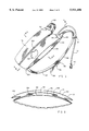
FIG. 3 is a view of the top and side of the drinking system;
FIG. 4 is longitudinal, cross-sectional view taken along lines 5--5 in FIG. 3;
FIG. 5 is a view of a person orally activating the valve apparatus with their tongue;
FIG. 6 is a view of a person orally activating the valve apparatus with their teeth;
FIG. 7 is a view of a person orally activating the valve apparatus with their teeth in a different manner than in FIG. 6;
FIG. 8 is a cross-sectional view taken along lines 6--6 in FIG. 3;
FIG. 9 is a longitudinal view with the valve in the normally closed position;
FIG. 10 is a longitudinal, cross-sectional view taken along lines 3--3 in FIG. 12 with the valve in the normally close position;
FIG. 11 is another longitudinal, cross-sectional view taken along lines 3--3 in FIG. 12 with the valve being in the open position; and
FIG. 12 is an end view of the apparatus disclosed in FIGS. 9, 10 and 11 taken along lines 4--4 in FIG. 9.
DETAILED DESCRIPTION OF THE PREFERRED EMBODIMENT
In FIG. 1 there is shown a bicycle 144 being ridden by a rider or bicyclist 146. The bicyclist has a pack or drinking system 140, made in accordance with the present invention, attached to his back and elevated higher than his mouth 148. A flexible tube 54 leads from the pack 140 to the bicyclist's mouth.
In FIG. 2 there is shown a hiker 152 with the pack 140, made in accordance with the present invention, attached to his back and positioned below his mouth 154. A flexible tube 54 leads from the pack 140 to the hiker's mouth.
In FIG. 3 it is seen that the pack 140 is partially filled with liquid and/or carry items. Items are stored within the drinking system by opening the zipper 120 in the main pocket upper panel 72 and placing the items inside the expandable area 66. A folded gusset panel 122 connects the main pocket upper panel 72 to the rest of the system and allows storage area expansion while allowing the main pocket upper panel 72 to lay substantially flat to the panels beneath when the storage area 66 is empty. Upper straps 92 connect to a fill port flap 98 through slots in the strap guides 86 to ladder lock buckles 56. Lower straps 93 attach to the end of the system 134 and are routed through the ladder lock buckles 56. With the system removably secured at a location between the shoulders of the user to tighten the strap system, the user pulls down on strap end 95. To loosen the strap system, the user pulls up on the ladder lock buckle tip 58.
Tubing 54 exits the bag system through either one of two slot openings 80 in the main pocket upper panel 72 depending on which side the user prefers. The tubing then routes through a tubing guide 84. The tubing guide 84 can be moved to support the tubing 54 at different positions, along the strap 92, depending on the user preference. Finally, the tubing 54 is connected to the orally activated valve apparatus 90.
As shown in FIG. 4, the system comprises an insulating panel 118, a lower bladder panel 114, an upper bladder panel 60, a flexible tube 54, an orally activated valve apparatus 90, straps 92, lower pocket panel 78, upper auxiliary pocket panel and closure flap 68 and 76 respectively, and a main pocket upper panel 72. Liquid is stored within the chamber 106 that is formed of lower bladder panel 114 and upper bladder panel 60. Bladder panels 114 and 60 are connected by heat sealing such as by radio frequency welding or gluing. Bladder panels 114 and 60 are made of materials such as urethane coated nylon packcloth that can seal liquid within. A fill port cap 100 seals against a fill port 94 which is sealed to the lower bladder panel 114 by heat sealing in the same manner as the bladder panels.
During the filling operation, upper surfaces 96 of the legs 102 of the fill port 94 prevent the inner surface 104 of the upper bladder panel 60 from effectively sealing against the port 94 and thus allow liquid to easily enter the chamber 106 relatively unimpeded and without special care required to orient surface 104 away from fill port 94.
While liquid can be purposedly evacuated through the fill port 94 by removing the fill port cap 100 and holding the system upside down, the liquid normally exits chamber 106 via an elbow 62 which is heat sealed to the upper bladder panel 60 at area 116 and is hollow to allow liquid flow therethrough. Tubing 54 is connected to the elbow 62 at area 64 by glue, press fit, or by adding a barbed hollow male/male fitting (not shown) between the elbow 62 and the tubing 54. The tubing 54 is routed between the upper bladder panel 60 and the lower pocket panel 78 and exits the system through a large opening 156 in the lower pocket panel 78 and then through either of two openings 80 depending on user preference, in the main pocket upper panel 72 in line with a shoulder strap 92, as best shown in FIG. 3. The tubing is then routed through a tubing guide 84. Tubing guide 84 can be moved to support the tubing 54 at different positions along the strap 92 depending on user preference. Finally, the tubing 54 is connected to the orally activated valve apparatus 90.
The main expandable storage area 66 is created by the upper bladder panel 60, auxiliary pocket panel 68 and closure flap 76, two gusset panels 122 as best shown in FIG. 8, and the main pocket upper panel 72. A zipper 120 provides access to and closure of area 66 as shown in FIG. 3.
An expandable storage area 70 is created by the auxiliary pocket panel 68, closure flap 76, and the lower auxiliary pocket panel 78. Auxiliary panel 68 is folded to allow expansion. The closure flap 76 is secured to the auxiliary pocket panel 68 with a hook and loop fastener 74. The closure flap 76 overlaps the auxiliary pocket panel 68 so that the closure flap 76 can still be fastened to the auxiliary pocket panel 68 with the hook and loop fastener 74 even when area 70 is filled to capacity to a fully expanded state.
An insulating panel 118 is attached to the lower bladder panel 114 from the end 134 of the system to the hinge line 136 and insulates the liquid within a chamber 106 from ambient and the user's body heat. The insulating panel is made of flexible foam laminated on both sides with an abrasion resistant material such as nylon cloth and is embossed to form channels 110 and ribs 108. The surfaces 112 of ribs 108 are in contact with the user's body at a location between the shoulders. The embossed channels 110 allow air to vent between the drinking system and the user's body. The fill port flap 98, which is a continuation of insulating panel 118, hinges along line 136 in order to expose the fill port 94 and fill port cap 100 for filling chamber 106 with liquid. Straps 92 attach to the fill port flap 98 at area 158 and are routed through the strap guide 86 slots 88. The length of the lower bladder panel 114 from hinge point 136 to the end of strap guide 86, which contains the fill port 94, is slightly longer than the fill port flap 98 from hinge point 136 to area 158. When the straps 92 are pulled tight, such as when removably securing the container at a location between the shoulders of the user, the fill port flap 98 is relatively straight against the user's body and the fill port mounted area of the lower bladder panel 114 is forced to curve holding the fill port 94 slightly separated from the backside of the fill port flap panel 98. This prevents uncomfortable point pressure that the fill port cap 100 might otherwise exert against the user's body.
FIG. 5 shows a person orally activating the valve apparatus with his or her tongue. The user's upper and lower lips, 130 and 132 respectively, are shown distant from the valve apparatus in order to show the activation more clearly. The user is holding the valve apparatus 90 by biting gently with his or her upper and lower teeth, 124 and 126 respectively, on surface 44. To drink, the user would close his or her lips, 130 and 132, around surface 42 or 44 of the valve apparatus 90, and push his or her tongue 128 against the valve plunger 26. Surface 16 of the ring cap 28 prevents the valve apparatus 90 from being pushed out of one's mouth without the need to bite hard on surface 44. Oral suction also generally helps retain the valve apparatus while ingesting the liquid. If the liquid container is at a location higher than the valve apparatus 90, such as in FIG. 1, then hydrostatic pressure will cause liquid to flow without the need for suction. If the liquid container is at a location lower then the valve apparatus 90, such as in FIG. 2, then the user will need to create suction with their mouth in order to ingest the liquid. The person can also hold the valve apparatus 90 between his or her teeth without depressing the valve plunger 26 so that he or she can breathe without activating the valve apparatus.
FIG. 6 shows a person orally activating the valve apparatus with his or her teeth. The user's upper and lower lips, 130 and 132 respectively, are shown distant from the valve apparatus in order to show the activation more clearly. The user is holding the valve apparatus 90 with his or her upper teeth 124 against surface 16 of the ring cap 28 and his or her lower teeth 126 against valve plunger 26. To drink, the user would close his or her lips, 130 and 132, around surface 42 or 44 of the valve apparatus 90, and bite against the valve plunger 26. Surface 16 of the ring cap 28 and lip pressure against surfaces 42, 12, 44 and/or 16 prevent the valve apparatus 90 from being pushed out of one's mouth. Oral suction also generally helps retain the valve apparatus while ingesting the liquid. If the liquid container is at a location higher than the valve apparatus 90, then hydrostatic pressure will cause liquid to flow without the need for suction. If the liquid container is at a location lower then the valve apparatus 90, then the user will need to create suction with his or her mouth in order to ingest the liquid.
FIG. 7 shows a person orally activating the valve apparatus with his or her teeth in a manner different than in FIG. 6. The user's upper and lower lips, 130 and 132 respectively, are shown distant from the valve apparatus in order to show the activation more clearly. The user is holding the valve apparatus 90 with his or her lower teeth 126 against surface 16 of the ring cap 28 and his or her upper teeth 124 against valve plunger 26. To drink, the user would close his or her lips, 130 and 132, around surface 42 or 44 of the valve apparatus 90, and bite against the valve plunger 26. Surface 16 of the ring cap 28 and lip pressure against surfaces 42, 12, 44 and/or 16 prevent the valve apparatus 90 from being pushed out of one's mouth. Oral suction also generally helps retain the valve apparatus while ingesting the liquid. If the liquid container is at a location higher than the valve apparatus 90, then hydrostatic pressure will cause liquid to flow without the need for suction. If the liquid container is at a location lower then the valve apparatus 90, then the user will need to create suction with his or her mouth in order to ingest the liquid.
In FIG. 8, the valve shown is a cross-sectional view looking in the direction of lines 6--6 in FIG. 3. Gusset panels 122 attach the upper bladder panel 60 to the main pocket upper panel 72. Because of the fold in gusset panel 122, the main pocket upper panel 72 is free to move away from the upper bladder panel 60 to accommodate stored items within the main pocket storage area 66 and the auxiliary pocket storage area 70. Similarly folds 138 within the upper auxiliary pocket panel 68 act as gussets to expand when items are stored within area 70. Gussets 122 and folds 138 also freely collapse to provide a relatively streamlined system when area 66 and/or 70 are empty.
In FIG. 9, the valve is shown in a longitudinal view in the normally closed position. The user can hold the valve within his or her mouth by holding surfaces 42 and 44 between the teeth or lips. Surfaces 12 and 16 prevent the valve from slipping out of the user's mouth without having to apply large force against surfaces 42 or 44. By pushing against the valve plunger 26 on surface 22 with his or her tongue or teeth, the user orally opens the valve.
In FIG. 10, the valve is shown in a longitudinal, cross-sectional view in the normally closed position. Flexible tubing 54 has been pushed onto the barbed portion of valve body 34 and is secured in place by the barb 10. The angled surface 40 of the valve body 34 allows easy installation of the flexible tube 54 while the barb 10 prevents accidental separation and still allows purposeful separation for cleaning or replacement, if necessary.
The ring cap 28 is bonded to the valve body 34 at attachment area 18 by glue, ultrasonic welding, screw threads, tight press fit or other appropriate means which both seals the parts together and prevents separation. Inside this ring cap 28 and valve body 34 there are a valve plunger 26, an O-ring 32, and a compression spring 38. The O-ring 32 seals against surface 24 of the valve plunger 26 and is biased into a closed position against sealing surface 30 of the ring cap 28 by the compression spring 38 and hydrostatic pressure that is present if the liquid container is higher than the valve apparatus 90. The ends of compression spring 38 are held in position at one end by the valve body surface 50 and at the other end by the valve plunger surface 52.
In FIG. 11, the valve is shown with enough force applied to the valve plunger 26 on surface 22 to overcome the force applied from the compression spring 38 and any hydrostatic pressure causing the valve plunger 26 to have moved such that the O-ring 32 is no longer in contact with the ring cap surface 30. This plunger position connects the valve chamber 14 to ambient and allows liquid within the valve chamber 14 to flow down the tube, along the valve plunger ribs 36, around the O-ring 32 and out through the flow channel 20. Each flow channel 20 is sufficiently small in cross-section to prevent liquid from dripping from the valve after valve closure occurs. In the preferred embodiment, in order to obtain the maximum flow that the tube can provide, all of the areas within the valve assembly that the liquid passes through, should be sized such that they are equal to or bigger than the flow area of the tube. The valve plunger 26 is aligned to the spring 38 by the multiple ribs 36 of the valve plunger 26 close proximity to compression spring 38 internal diameter. The compression spring 38 is aligned to the valve body 26 by the outer diameter of the compression spring 38 close proximity to the internal diameter of the valve body 34.
In FIG. 12, the valve is shown in an end view. The multiple surfaces 46 of the valve plunger 26 align the valve plunger 26 to the ring cap 28 while the flow channels 20 allow liquid to flow through with minimal restriction. To achieve maximum flow, the total area between the valve plunger 26 and the ring cap 28 should be equal to or greater than the flow area of the tube 54 shown in FIG. 10. The surface 22 of the valve plunger 26 is free of distortions and sharp areas that could cause discomfort against the user's tongue. The valve plunger 26 is aligned to the ring cap 28 by alignment surface 46 close proximity to the ring cap 28 opening diameter 48. The generally round shape of the ring cap 28, the valve plunger 26 and the valve body 34, allow use of the valve apparatus 90 without regard for rotational orientation.

Claims (2)

Having thus disclosed a preferred, illustrative embodiment of the present invention, the structure, operation and general principles thereof now being readily apparent, we claim:
1. An orally activated valve for use with a liquid delivery system to which the valve is connected by a tube, the valve comprising:
a hard, elongated housing having an inlet located at a first end of said housing and a plurality of short outlets located at a second end of said housing and a flow path extending in an axial direction therebetween, the inlet being connected to said tube, the outlets having a spring biased sealing device therein for selective opening of said outlets, an annular ring cap attached to an outer periphery of the housing second end, the annular ring cap being configured for oral retention in the mouth of the user, the sealing device being a plunger, said plunger having an outer peripheral wall engaging said ring cap for limiting plunger movement to the axial direction for unsealing the outlets in response to an axial depression force by the tongue of the user whereby a liquid flows directly from said inlet to said outlets, said plunger being axially biased contiguous said housing for fluidly blocking said plurality of short outlets when said depression force is removed;
said movable plunger extending beyond said housing second end for ease of access by the tongue of the user.
2. The valve recited in claim 1 wherein said housing is configured for retention between the user's teeth without activation.
US08/529,080 1995-09-15 1995-09-15 Liquid dispensing and item storage system with orally activated valve Expired - Fee Related US5911406A (en)

Priority Applications (1)

Application Number Priority Date Filing Date Title
US08/529,080 US5911406A (en) 1995-09-15 1995-09-15 Liquid dispensing and item storage system with orally activated valve

Applications Claiming Priority (1)

Application Number Priority Date Filing Date Title
US08/529,080 US5911406A (en) 1995-09-15 1995-09-15 Liquid dispensing and item storage system with orally activated valve

Publications (1)

Publication Number Publication Date
US5911406A true US5911406A (en) 1999-06-15

Family

ID=24108448

Family Applications (1)

Application Number Title Priority Date Filing Date
US08/529,080 Expired - Fee Related US5911406A (en) 1995-09-15 1995-09-15 Liquid dispensing and item storage system with orally activated valve

Country Status (1)

Country Link
US (1) US5911406A (en)

Cited By (54)

* Cited by examiner, † Cited by third party
Publication number Priority date Publication date Assignee Title
US6264166B1 (en) * 2001-03-05 2001-07-24 Mark A. Bowland Hands-free activating valve for use with liquid containers
US6314984B1 (en) * 1999-08-05 2001-11-13 Casa Artiach S.A. Preferred valve stops with cushions
US20020113101A1 (en) * 2000-09-01 2002-08-22 Jeff Skillern Hydration pouch with integral thermal medium
EP1260151A2 (en) * 2001-05-14 2002-11-27 Berghaus Limited Improved rucksack
US20030075573A1 (en) * 2001-10-22 2003-04-24 Trek Bicycle Corp. Dual bladder sports hydration system
WO2003068035A2 (en) 2002-02-12 2003-08-21 Hydrapak Fluid dispensing and storage system with a drink valve
US20030173536A1 (en) * 2002-03-15 2003-09-18 Christensen Mark A. Bite valve
US6622988B2 (en) * 2000-09-14 2003-09-23 Source Vagabond Systems Ltd. Mouthpiece for drinking
US6651694B1 (en) * 2001-07-17 2003-11-25 The Protector Corporation Insulating cover and method for liquid supply tube
US20040045980A1 (en) * 2002-09-06 2004-03-11 Robins Duncan G. Personal hydration system with pump
US6719273B1 (en) * 2002-11-16 2004-04-13 Shih-Sheng Yang Water outlet valve for water bag mouthpiece
US6722533B2 (en) 2002-02-26 2004-04-20 Jeff Skillern Hydration pouch with detachable hose
US6742681B1 (en) * 2003-03-27 2004-06-01 Shih-Sheng Yang Structure of a water outlet valve for water bag mouthpieces
US20040103684A1 (en) * 2002-10-10 2004-06-03 Stokley-Van Camp, Inc. In-car hydration systems
US6745594B2 (en) 2002-10-10 2004-06-08 Stokley-Van Camp, Inc. In-car hydration systems
US6755047B2 (en) 2002-10-10 2004-06-29 Stokley-Van Camp, Inc. In-car hydration systems
US20050029313A1 (en) * 2003-05-08 2005-02-10 Fiskars Brands, Inc. Personal hydration system
US20050061831A1 (en) * 2001-01-26 2005-03-24 Brown Dennis B. Multispout hydration system
US6886807B1 (en) 2001-08-08 2005-05-03 Yoram Gill Bite valve for drinking with integral spring
US20050150894A1 (en) * 2004-01-09 2005-07-14 Stribling Robert P. Leakage protection
FR2867382A1 (en) 2004-03-10 2005-09-16 Anne Marie Pontis Buccal insert for administering or extracting a fluid occupies sufficient volume in the mouth to prevent accidental removal
US20050242204A1 (en) * 2004-04-30 2005-11-03 Ness Richard A Leak-resistant drinking systems
US20060163284A1 (en) * 2005-01-27 2006-07-27 Fiskars Brands, Inc. Personal hydration system
US20060201955A1 (en) * 2004-01-09 2006-09-14 The Last Straw, Llc Snap-fit valve
US20060226110A1 (en) * 2005-04-11 2006-10-12 Robert Choi Drink bottles with bite-actuated mouthpieces
US20070012733A1 (en) * 2004-08-10 2007-01-18 Michael Horito Bite valve retainer
US20070012732A1 (en) * 2005-07-14 2007-01-18 Adams Shawn M Wearable drinking container (Hands free ) X shape
US20070090319A1 (en) * 2003-07-24 2007-04-26 Bw Technologies Ltd. Valves for drinking vessels
US20070108238A1 (en) * 2005-11-15 2007-05-17 Andrew Kirker Personal beverage supply assembly
US20070119866A1 (en) * 2005-11-15 2007-05-31 Sheppard Jeffry T Drink delivery apparatus and method for race car drivers
WO2007129014A1 (en) * 2006-05-05 2007-11-15 No Fuss Limited Emergency breathing apparatus
US20070280565A1 (en) * 2006-06-02 2007-12-06 Hydrapak, Inc. Reservoir system and method
US20080169321A1 (en) * 2007-01-11 2008-07-17 Paul Fidrych Hydration System for Use with a Pack
US20080277433A1 (en) * 2007-03-19 2008-11-13 Fiskars Brands, Inc. Modular personal hydration and storage system
US20090302261A1 (en) * 2008-02-07 2009-12-10 Polar Design, Inc. Self-sealing bite valve
US20100044396A1 (en) * 2006-08-14 2010-02-25 Jeff Skillern Pressurized hydration system
WO2010077196A1 (en) * 2008-12-30 2010-07-08 Uswe International Ab Mobile hydration system
US20100243756A1 (en) * 2009-02-27 2010-09-30 Paul Stuart Auerbach Avalanche rescue device
US7819293B1 (en) 2004-05-19 2010-10-26 O'connell Thomas P Replenishable drinking vessel
US20130037583A1 (en) * 2011-08-12 2013-02-14 David M. Graff Underwater drinking apparatus
WO2013163104A1 (en) * 2012-04-24 2013-10-31 Rx Hydration, Inc. Systems, kits and methods for hands free, on demand, oral delivery of materials
US8672197B2 (en) 2011-02-20 2014-03-18 Matthew Charles Piazza Liquid dispenser
ITPD20130205A1 (en) * 2013-07-24 2015-01-25 2M Di Mozzato Germano SPORTS BOTTLE AND PARTICULARLY FOR CYCLING
US9220854B1 (en) * 2006-12-24 2015-12-29 Mark Okrusko Breath bellows
US20170121069A1 (en) * 2015-10-20 2017-05-04 Sagan Industries Llc Quick connect mouthpiece for liquid container
US9828982B1 (en) 2014-06-24 2017-11-28 Sporting Innovations, Llc Electric pump and delivery tube for personal hydration system
US10358270B1 (en) 2018-05-31 2019-07-23 Camelbak Products, Llc Closure assemblies and drink containers including the same
USD862985S1 (en) 2018-05-31 2019-10-15 Camelbak Products, Llc Beverage container
USD864658S1 (en) 2018-05-31 2019-10-29 Camelbak Products, Llc Beverage container closure
USD871836S1 (en) 2018-05-31 2020-01-07 Camelbak Products, Llc Bite-actuated mouthpiece
US10532862B2 (en) 2018-06-19 2020-01-14 Camelbak Products, Llc Closure assemblies with distinct dispensing modes and drink containers including the same
USD881639S1 (en) 2018-06-19 2020-04-21 Camelbak Products, Llc Beverage container closure
USD901238S1 (en) 2018-05-31 2020-11-10 Camelbak Products, Llc Bite-actuated mouthpiece
US11877984B1 (en) * 2020-02-12 2024-01-23 Robert F. Thomas Saliva solution metering apparatus with delivery tube retaining mouthpiece

Citations (16)

* Cited by examiner, † Cited by third party
Publication number Priority date Publication date Assignee Title
US2815981A (en) * 1954-05-13 1957-12-10 William M Nonnamaker Drink mixing and sipping device
US3646955A (en) * 1969-05-08 1972-03-07 Jarl Rune Olde Water-feeding device
US3822720A (en) * 1971-03-04 1974-07-09 Noyce R Flow control assembly
US4090650A (en) * 1976-07-26 1978-05-23 Gotta Harold J Canteen with a straw
US4095812A (en) * 1977-01-05 1978-06-20 Rowe V Lopez Bicycle drinking apparatus
US4402343A (en) * 1979-01-12 1983-09-06 Earl Clayton Thompson Animal watering valve with protected biasing spring
US4629098A (en) * 1984-10-15 1986-12-16 Eger Douglas R Portable liquid dispenser
US4739905A (en) * 1985-06-24 1988-04-26 Nelson Steve R Beverage dispensing device
US4776495A (en) * 1986-04-16 1988-10-11 Alpha Systemes Disposable dispenser pump for products in liquid or paste form
US4852781A (en) * 1987-11-17 1989-08-01 Shurnick Carl W Runner's portable fluid supply container
US4941598A (en) * 1988-11-08 1990-07-17 Ortho Pharmaceutical Corporation Dosing cap
US4948023A (en) * 1987-12-07 1990-08-14 Tripp Gordon R Fluid storing and supply means
US5060833A (en) * 1989-08-14 1991-10-29 Fastrak Systems, Inc. Camel back
US5065700A (en) * 1990-10-17 1991-11-19 Se Lab Group, Inc. Shutter for animal-watering valve
US5085349A (en) * 1990-02-08 1992-02-04 Fawcett Roger R Resilient valve and dispensing system for bicyclists
US5104016A (en) * 1990-02-12 1992-04-14 Bikestream, Inc. Pressurized potable beverage drinking system

Patent Citations (16)

* Cited by examiner, † Cited by third party
Publication number Priority date Publication date Assignee Title
US2815981A (en) * 1954-05-13 1957-12-10 William M Nonnamaker Drink mixing and sipping device
US3646955A (en) * 1969-05-08 1972-03-07 Jarl Rune Olde Water-feeding device
US3822720A (en) * 1971-03-04 1974-07-09 Noyce R Flow control assembly
US4090650A (en) * 1976-07-26 1978-05-23 Gotta Harold J Canteen with a straw
US4095812A (en) * 1977-01-05 1978-06-20 Rowe V Lopez Bicycle drinking apparatus
US4402343A (en) * 1979-01-12 1983-09-06 Earl Clayton Thompson Animal watering valve with protected biasing spring
US4629098A (en) * 1984-10-15 1986-12-16 Eger Douglas R Portable liquid dispenser
US4739905A (en) * 1985-06-24 1988-04-26 Nelson Steve R Beverage dispensing device
US4776495A (en) * 1986-04-16 1988-10-11 Alpha Systemes Disposable dispenser pump for products in liquid or paste form
US4852781A (en) * 1987-11-17 1989-08-01 Shurnick Carl W Runner's portable fluid supply container
US4948023A (en) * 1987-12-07 1990-08-14 Tripp Gordon R Fluid storing and supply means
US4941598A (en) * 1988-11-08 1990-07-17 Ortho Pharmaceutical Corporation Dosing cap
US5060833A (en) * 1989-08-14 1991-10-29 Fastrak Systems, Inc. Camel back
US5085349A (en) * 1990-02-08 1992-02-04 Fawcett Roger R Resilient valve and dispensing system for bicyclists
US5104016A (en) * 1990-02-12 1992-04-14 Bikestream, Inc. Pressurized potable beverage drinking system
US5065700A (en) * 1990-10-17 1991-11-19 Se Lab Group, Inc. Shutter for animal-watering valve

Cited By (92)

* Cited by examiner, † Cited by third party
Publication number Priority date Publication date Assignee Title
US6314984B1 (en) * 1999-08-05 2001-11-13 Casa Artiach S.A. Preferred valve stops with cushions
US20020113101A1 (en) * 2000-09-01 2002-08-22 Jeff Skillern Hydration pouch with integral thermal medium
US6622988B2 (en) * 2000-09-14 2003-09-23 Source Vagabond Systems Ltd. Mouthpiece for drinking
US20050061831A1 (en) * 2001-01-26 2005-03-24 Brown Dennis B. Multispout hydration system
US6264166B1 (en) * 2001-03-05 2001-07-24 Mark A. Bowland Hands-free activating valve for use with liquid containers
EP1260151A3 (en) * 2001-05-14 2003-05-28 Berghaus Limited Improved rucksack
EP1260151A2 (en) * 2001-05-14 2002-11-27 Berghaus Limited Improved rucksack
US6651694B1 (en) * 2001-07-17 2003-11-25 The Protector Corporation Insulating cover and method for liquid supply tube
US6886807B1 (en) 2001-08-08 2005-05-03 Yoram Gill Bite valve for drinking with integral spring
US20030075573A1 (en) * 2001-10-22 2003-04-24 Trek Bicycle Corp. Dual bladder sports hydration system
US6749090B2 (en) * 2001-10-22 2004-06-15 Trek Bicycle Corporation Dual bladder sports hydration system
WO2003068035A2 (en) 2002-02-12 2003-08-21 Hydrapak Fluid dispensing and storage system with a drink valve
US6764064B2 (en) 2002-02-12 2004-07-20 Hydrapak Fluid dispensing and storage system with a drink valve
US6722533B2 (en) 2002-02-26 2004-04-20 Jeff Skillern Hydration pouch with detachable hose
US20030173536A1 (en) * 2002-03-15 2003-09-18 Christensen Mark A. Bite valve
US6708950B2 (en) * 2002-03-15 2004-03-23 Wolfe Tory Medical Bite valve
US20040045980A1 (en) * 2002-09-06 2004-03-11 Robins Duncan G. Personal hydration system with pump
US6851275B2 (en) 2002-10-10 2005-02-08 Stokely-Van Camp, Inc. In-car hydration systems
US7007502B2 (en) 2002-10-10 2006-03-07 Stokely-Van Camp, Inc. In-car hydration systems
US6745594B2 (en) 2002-10-10 2004-06-08 Stokley-Van Camp, Inc. In-car hydration systems
US6755047B2 (en) 2002-10-10 2004-06-29 Stokley-Van Camp, Inc. In-car hydration systems
US20040103684A1 (en) * 2002-10-10 2004-06-03 Stokley-Van Camp, Inc. In-car hydration systems
US20050034478A1 (en) * 2002-10-10 2005-02-17 Stokley-Van Camp. Inc. In-car hydration systems
US6719273B1 (en) * 2002-11-16 2004-04-13 Shih-Sheng Yang Water outlet valve for water bag mouthpiece
US6742681B1 (en) * 2003-03-27 2004-06-01 Shih-Sheng Yang Structure of a water outlet valve for water bag mouthpieces
US20050029313A1 (en) * 2003-05-08 2005-02-10 Fiskars Brands, Inc. Personal hydration system
US20050029319A1 (en) * 2003-05-08 2005-02-10 Fiskars Brands, Inc. Personal hydration system
US7490740B2 (en) 2003-05-08 2009-02-17 Fiskars Brands, Inc. Personal hydration system
US20070090319A1 (en) * 2003-07-24 2007-04-26 Bw Technologies Ltd. Valves for drinking vessels
US7934620B2 (en) * 2004-01-09 2011-05-03 The Last Straw, Llc Leakage protection
US20050150894A1 (en) * 2004-01-09 2005-07-14 Stribling Robert P. Leakage protection
US7837056B2 (en) * 2004-01-09 2010-11-23 The Last Straw Llc Snap-fit valve
US20060201955A1 (en) * 2004-01-09 2006-09-14 The Last Straw, Llc Snap-fit valve
FR2867382A1 (en) 2004-03-10 2005-09-16 Anne Marie Pontis Buccal insert for administering or extracting a fluid occupies sufficient volume in the mouth to prevent accidental removal
US20080161750A1 (en) * 2004-03-10 2008-07-03 Anne-Marie Pontis Oral Fluid Delivery or Sampling Device
WO2005087176A1 (en) 2004-03-10 2005-09-22 Anne-Marie Pontis Oral fluid delivery or sampling device
US20050242204A1 (en) * 2004-04-30 2005-11-03 Ness Richard A Leak-resistant drinking systems
US7819293B1 (en) 2004-05-19 2010-10-26 O'connell Thomas P Replenishable drinking vessel
US20070012733A1 (en) * 2004-08-10 2007-01-18 Michael Horito Bite valve retainer
US20070181616A9 (en) * 2004-08-10 2007-08-09 Michael Horito Bite valve retainer
US20060163284A1 (en) * 2005-01-27 2006-07-27 Fiskars Brands, Inc. Personal hydration system
US7600656B2 (en) 2005-01-27 2009-10-13 Fiskars Brands, Inc. Personal hydration system
US20080237233A1 (en) * 2005-04-11 2008-10-02 Camelbak Products, Llc Drink bottles
US20070039959A1 (en) * 2005-04-11 2007-02-22 Robert Choi Drink bottles with bite-actuated mouthpieces
US11851250B2 (en) 2005-04-11 2023-12-26 Camelbak Products, Llc Drink bottles
US8622237B2 (en) 2005-04-11 2014-01-07 Camelbak Products, Llc Drink bottles with bite-actuated mouthpieces
US11242178B2 (en) 2005-04-11 2022-02-08 Camelbak Products, Llc Drink bottles
US8777048B2 (en) 2005-04-11 2014-07-15 Camelbak Products, Llc Drink bottles
US7533783B2 (en) 2005-04-11 2009-05-19 Camelbak Products, Llc Drink bottles with bite-actuated mouthpieces
US20060226110A1 (en) * 2005-04-11 2006-10-12 Robert Choi Drink bottles with bite-actuated mouthpieces
US9463911B2 (en) 2005-04-11 2016-10-11 Camelbak Products, Llc Drink bottles
US10023365B2 (en) 2005-04-11 2018-07-17 Camelbak Products, Llc Drink bottles
US10676255B2 (en) 2005-04-11 2020-06-09 Camelbak Products, Llc Drink bottles
US20070012732A1 (en) * 2005-07-14 2007-01-18 Adams Shawn M Wearable drinking container (Hands free ) X shape
US7552734B2 (en) * 2005-07-14 2009-06-30 Shawn Maurice Adams Wearable drinking container (hands free ) X shape
US20070108238A1 (en) * 2005-11-15 2007-05-17 Andrew Kirker Personal beverage supply assembly
US20070119866A1 (en) * 2005-11-15 2007-05-31 Sheppard Jeffry T Drink delivery apparatus and method for race car drivers
US20090173342A1 (en) * 2006-05-05 2009-07-09 No Fuss Limited Emergency breathing apparatus
WO2007129014A1 (en) * 2006-05-05 2007-11-15 No Fuss Limited Emergency breathing apparatus
US20070280565A1 (en) * 2006-06-02 2007-12-06 Hydrapak, Inc. Reservoir system and method
US20100044396A1 (en) * 2006-08-14 2010-02-25 Jeff Skillern Pressurized hydration system
US8540122B2 (en) 2006-08-14 2013-09-24 Oakley, Inc. Pressurized hydration system
US9220854B1 (en) * 2006-12-24 2015-12-29 Mark Okrusko Breath bellows
US7762432B2 (en) * 2007-01-11 2010-07-27 Nike, Inc. Hydration system for use with a pack
US20100264175A1 (en) * 2007-01-11 2010-10-21 Nike, Inc. Hydration System For Use With A Pack
US20080169321A1 (en) * 2007-01-11 2008-07-17 Paul Fidrych Hydration System for Use with a Pack
US7975880B2 (en) 2007-01-11 2011-07-12 Nike, Inc. Hydration system for use with a pack
US20080277433A1 (en) * 2007-03-19 2008-11-13 Fiskars Brands, Inc. Modular personal hydration and storage system
US8152138B2 (en) * 2008-02-07 2012-04-10 Oakley, Inc. Self-sealing bite valve
US20090302261A1 (en) * 2008-02-07 2009-12-10 Polar Design, Inc. Self-sealing bite valve
WO2010077196A1 (en) * 2008-12-30 2010-07-08 Uswe International Ab Mobile hydration system
US20100243756A1 (en) * 2009-02-27 2010-09-30 Paul Stuart Auerbach Avalanche rescue device
US8061293B2 (en) * 2009-02-27 2011-11-22 Paul Stuart Auerbach Avalanche rescue device
US8672197B2 (en) 2011-02-20 2014-03-18 Matthew Charles Piazza Liquid dispenser
US20130037583A1 (en) * 2011-08-12 2013-02-14 David M. Graff Underwater drinking apparatus
US10053356B2 (en) 2012-04-24 2018-08-21 Rx Hydration, Inc. Systems, kits and methods for hands free, on demand, oral delivery of materials
WO2013163104A1 (en) * 2012-04-24 2013-10-31 Rx Hydration, Inc. Systems, kits and methods for hands free, on demand, oral delivery of materials
WO2015010873A1 (en) * 2013-07-24 2015-01-29 Raceone S.R.L. Sports flask, particularly for cycling
ITPD20130205A1 (en) * 2013-07-24 2015-01-25 2M Di Mozzato Germano SPORTS BOTTLE AND PARTICULARLY FOR CYCLING
US9828982B1 (en) 2014-06-24 2017-11-28 Sporting Innovations, Llc Electric pump and delivery tube for personal hydration system
US20170121069A1 (en) * 2015-10-20 2017-05-04 Sagan Industries Llc Quick connect mouthpiece for liquid container
US10358270B1 (en) 2018-05-31 2019-07-23 Camelbak Products, Llc Closure assemblies and drink containers including the same
USD876895S1 (en) 2018-05-31 2020-03-03 Camelbak Products, Llc Beverage container
USD884419S1 (en) 2018-05-31 2020-05-19 Camelbak Products, Llc Beverage container closure
USD871836S1 (en) 2018-05-31 2020-01-07 Camelbak Products, Llc Bite-actuated mouthpiece
USD893941S1 (en) 2018-05-31 2020-08-25 Camelbak Products, Llc Mouthpiece
USD901238S1 (en) 2018-05-31 2020-11-10 Camelbak Products, Llc Bite-actuated mouthpiece
USD864658S1 (en) 2018-05-31 2019-10-29 Camelbak Products, Llc Beverage container closure
USD862985S1 (en) 2018-05-31 2019-10-15 Camelbak Products, Llc Beverage container
US10532862B2 (en) 2018-06-19 2020-01-14 Camelbak Products, Llc Closure assemblies with distinct dispensing modes and drink containers including the same
USD881639S1 (en) 2018-06-19 2020-04-21 Camelbak Products, Llc Beverage container closure
US11877984B1 (en) * 2020-02-12 2024-01-23 Robert F. Thomas Saliva solution metering apparatus with delivery tube retaining mouthpiece

Similar Documents

Publication Publication Date Title
US5911406A (en) Liquid dispensing and item storage system with orally activated valve
US5060833A (en) Camel back
US5085349A (en) Resilient valve and dispensing system for bicyclists
US6283344B1 (en) Hands free personal hydration delivery system
US8727244B2 (en) Fluid container and support bracket therefor
EP3487341B1 (en) Hydration system and components thereof
US6199729B1 (en) Hands-free drinking system
US6764064B2 (en) Fluid dispensing and storage system with a drink valve
US8777075B2 (en) Combination hydration, nutrition, and pack apparatus for a bicycle
US5816457A (en) Hydration system
US6820780B2 (en) Neck-supported fluid reservoir, hydration systems and pack assemblies including the same
US4629098A (en) Portable liquid dispenser
US5431308A (en) Apparatus for storing and dispensing fluids for use by an athlete
US5427290A (en) Water pouch backpack
US7201299B2 (en) Waist-mounted hydration system
US20060243765A1 (en) Pressurized personal hydration system and kit
US8136702B2 (en) Pressurized hydration system
US5571260A (en) Portable liquid container and dispenser system
US4526298A (en) Sport hydration system
US20090140005A1 (en) Pressurized fluid delivery system
AU2016102131A4 (en) A Personal Liquid Supply System
US20150001253A1 (en) Two Reservoir Fluid Delivery System
US20160243006A1 (en) Oral waste disposal device for chewing tobacco
US20040238549A1 (en) Packwedge
TW420644B (en) Water supply system used in sport use

Legal Events

Date Code Title Description
AS Assignment

Owner name: BELL SPORTS, INC., CALIFORNIA

Free format text: ASSIGNMENT OF ASSIGNORS INTEREST;ASSIGNORS:WINEFORDNER, CARL;HERMANSEN, FRANK;OLIVIERI, JEAN-CLAUDE;REEL/FRAME:011007/0183

Effective date: 20000405

AS Assignment

Owner name: FLEET NATIONAL BANK AS ADMINISTRATIVE AGENT, MASSA

Free format text: FIRST SUPPLEMENTAL PATENT COLLATERAL ASSIGNMENT AND SECURITY AGREEMENT, ATTACHED HERETO AS EXHIBIT 1.;ASSIGNOR:BELL SPORTS, INC;REEL/FRAME:011731/0001

Effective date: 20010321

REMI Maintenance fee reminder mailed
LAPS Lapse for failure to pay maintenance fees
STCH Information on status: patent discontinuation

Free format text: PATENT EXPIRED DUE TO NONPAYMENT OF MAINTENANCE FEES UNDER 37 CFR 1.362

FP Lapsed due to failure to pay maintenance fee

Effective date: 20030615