US5915661A - Collapsible desk stand for portable computer - Google Patents
Collapsible desk stand for portable computer Download PDFInfo
- Publication number
- US5915661A US5915661A US08/910,566 US91056697A US5915661A US 5915661 A US5915661 A US 5915661A US 91056697 A US91056697 A US 91056697A US 5915661 A US5915661 A US 5915661A
- Authority
- US
- United States
- Prior art keywords
- frame
- base
- support
- portions
- portable computer
- Prior art date
- Legal status (The legal status is an assumption and is not a legal conclusion. Google has not performed a legal analysis and makes no representation as to the accuracy of the status listed.)
- Expired - Fee Related
Links
Images

Classifications
-
- G—PHYSICS
- G06—COMPUTING; CALCULATING OR COUNTING
- G06F—ELECTRIC DIGITAL DATA PROCESSING
- G06F1/00—Details not covered by groups G06F3/00 - G06F13/00 and G06F21/00
- G06F1/16—Constructional details or arrangements
- G06F1/1613—Constructional details or arrangements for portable computers
- G06F1/163—Wearable computers, e.g. on a belt
-
- F—MECHANICAL ENGINEERING; LIGHTING; HEATING; WEAPONS; BLASTING
- F16—ENGINEERING ELEMENTS AND UNITS; GENERAL MEASURES FOR PRODUCING AND MAINTAINING EFFECTIVE FUNCTIONING OF MACHINES OR INSTALLATIONS; THERMAL INSULATION IN GENERAL
- F16M—FRAMES, CASINGS OR BEDS OF ENGINES, MACHINES OR APPARATUS, NOT SPECIFIC TO ENGINES, MACHINES OR APPARATUS PROVIDED FOR ELSEWHERE; STANDS; SUPPORTS
- F16M11/00—Stands or trestles as supports for apparatus or articles placed thereon Stands for scientific apparatus such as gravitational force meters
- F16M11/02—Heads
- F16M11/04—Means for attachment of apparatus; Means allowing adjustment of the apparatus relatively to the stand
- F16M11/06—Means for attachment of apparatus; Means allowing adjustment of the apparatus relatively to the stand allowing pivoting
- F16M11/10—Means for attachment of apparatus; Means allowing adjustment of the apparatus relatively to the stand allowing pivoting around a horizontal axis
-
- F—MECHANICAL ENGINEERING; LIGHTING; HEATING; WEAPONS; BLASTING
- F16—ENGINEERING ELEMENTS AND UNITS; GENERAL MEASURES FOR PRODUCING AND MAINTAINING EFFECTIVE FUNCTIONING OF MACHINES OR INSTALLATIONS; THERMAL INSULATION IN GENERAL
- F16M—FRAMES, CASINGS OR BEDS OF ENGINES, MACHINES OR APPARATUS, NOT SPECIFIC TO ENGINES, MACHINES OR APPARATUS PROVIDED FOR ELSEWHERE; STANDS; SUPPORTS
- F16M11/00—Stands or trestles as supports for apparatus or articles placed thereon Stands for scientific apparatus such as gravitational force meters
- F16M11/20—Undercarriages with or without wheels
- F16M11/24—Undercarriages with or without wheels changeable in height or length of legs, also for transport only, e.g. by means of tubes screwed into each other
- F16M11/38—Undercarriages with or without wheels changeable in height or length of legs, also for transport only, e.g. by means of tubes screwed into each other by folding, e.g. pivoting or scissors tong mechanisms
-
- F—MECHANICAL ENGINEERING; LIGHTING; HEATING; WEAPONS; BLASTING
- F16—ENGINEERING ELEMENTS AND UNITS; GENERAL MEASURES FOR PRODUCING AND MAINTAINING EFFECTIVE FUNCTIONING OF MACHINES OR INSTALLATIONS; THERMAL INSULATION IN GENERAL
- F16M—FRAMES, CASINGS OR BEDS OF ENGINES, MACHINES OR APPARATUS, NOT SPECIFIC TO ENGINES, MACHINES OR APPARATUS PROVIDED FOR ELSEWHERE; STANDS; SUPPORTS
- F16M13/00—Other supports for positioning apparatus or articles; Means for steadying hand-held apparatus or articles
-
- G—PHYSICS
- G06—COMPUTING; CALCULATING OR COUNTING
- G06F—ELECTRIC DIGITAL DATA PROCESSING
- G06F1/00—Details not covered by groups G06F3/00 - G06F13/00 and G06F21/00
- G06F1/16—Constructional details or arrangements
- G06F1/1613—Constructional details or arrangements for portable computers
- G06F1/1626—Constructional details or arrangements for portable computers with a single-body enclosure integrating a flat display, e.g. Personal Digital Assistants [PDAs]
-
- A—HUMAN NECESSITIES
- A47—FURNITURE; DOMESTIC ARTICLES OR APPLIANCES; COFFEE MILLS; SPICE MILLS; SUCTION CLEANERS IN GENERAL
- A47B—TABLES; DESKS; OFFICE FURNITURE; CABINETS; DRAWERS; GENERAL DETAILS OF FURNITURE
- A47B23/00—Bed-tables; Trays; Reading-racks; Book-rests, i.e. items used in combination with something else
- A47B23/04—Bed-tables; Trays; Reading-racks; Book-rests, i.e. items used in combination with something else supported from table, floor or wall
- A47B2023/049—Desk stand for laptop computer
-
- F—MECHANICAL ENGINEERING; LIGHTING; HEATING; WEAPONS; BLASTING
- F16—ENGINEERING ELEMENTS AND UNITS; GENERAL MEASURES FOR PRODUCING AND MAINTAINING EFFECTIVE FUNCTIONING OF MACHINES OR INSTALLATIONS; THERMAL INSULATION IN GENERAL
- F16M—FRAMES, CASINGS OR BEDS OF ENGINES, MACHINES OR APPARATUS, NOT SPECIFIC TO ENGINES, MACHINES OR APPARATUS PROVIDED FOR ELSEWHERE; STANDS; SUPPORTS
- F16M2200/00—Details of stands or supports
- F16M2200/02—Locking means
- F16M2200/021—Locking means for rotational movement
- F16M2200/024—Locking means for rotational movement by positive interaction, e.g. male-female connections
Definitions
- This disclosure relates to portable computers; in particular, to a stand that allows a hand-held computer to be propped up for the users' convenience to view the computer display and to be easily connected to peripheral devices, and to a hand strap assembly for such a portable computer.
- the stand includes a horizontal base, which rests on a surface such as a desk; a frame hingedly connected to the base, the computer being hung on the frame which can be propped at various angles relative to the base; and a support which props up the frame relative to the base.
- the stand folds flat along the hinge so that it can be easily transported.
- the angle of the support relative to the base determines the viewing angle of the computer on the frame.
- an adaptor plate detachably hangs by a flange from the frame; the adaptor plate is mounted to the computer docking port, to which the computer is conventionally made.
- the docking port further provides a conventional electrical connection between the computer and external, peripheral devices by cable.
- the docking port or the computer itself includes, on a rear surface, protruding hooks or flanges or equivalent members which thereby allow the computer or docking-port computer combination to hang from the frame member.
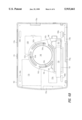
- the present FIG. 1 is identical to FIG. 7 of the above-referenced patent application illustrating the desk stand itself, without the computer, docking port or adaptor plate. These elements are shown in other figures of that patent application and hence not replicated herein.
- the desk stand is a relatively simple device made e.g. of metal, such as heavy gauge wire. It includes the base which includes member 2 at the front of the base. Mounted on either side of the base are adjustment plates 20a and 20b defining respectively holes 4 and slots 6 which accommodate respectively legs 18a and 18b of the frame 10.
- the frame 10 defines bends 36a and 36b although these are not necessary.
- the upper bar of frame 10 is member 10c; the lower portion of frame 10 is member 30. Frame 10 is propped up in the upright position is shown in FIG.
- Adjustment plate 20a further defines a hole 22a in which a support leg 24a of support member is inserted. The base rests on feet 39.
- the desk stand of FIG. 1 has been improved in several respects as disclosed herein.
- the bends 36a, 36b of FIG. 1 are eliminated. They are not needed in certain embodiments since they were intended to accommodate a computer having handles on its rear surface.
- the rear feet (at the back of the base of the stand) are modified in terms of their function so that in the collapsed position the upper cross bar member of the frame bears against one or both of these feet.
- a tight fit in the stand's collapsed position between the upper cross bar and the feet at the rear of the base allows locking of the frame against the base in the collapsed position.
- the adjustment plates are modified so that, rather than being in front of the frame (on the front part of the base), instead they are behind the frame, towards the rear of the base. This is sturdier since it results in greater distance between the pivots of the frame on the base and the point at which the frame is propped against the support. Also, these plates have four adjustment holes for 4 tilt angles.
- the end portions of the support extensions which fit into the holes in the adjustment plate have been provided with flanges so that they only enter the attachment plate holes to a predetermined extent.
- a new hand strap assembly for a portable computer allows use of such a computer at any orientation and with a variety of peripheral/accessory devices.
- FIG. 1 shows a computer desk stand from a copending patent application.
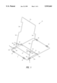
- FIG. 2 shows a perspective view of the present desk stand.
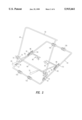
- FIG. 3 shows a side view of the desk stand of FIG. 2.
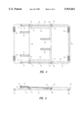
- FIG. 4 shows a top view of the FIG. 2 desk stand in a collapsed position.
- FIG. 5 shows a side view of the FIG. 4 desk stand in the collapsed position.
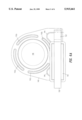
- FIGS. 6A, 6B show the present portable computer hand strap assembly.
- FIG. 2 shows a perspective view of the present desk stand. It is to be understood that this stand is used for a portable computer, as described in the above-referenced copending patent application. The portable computer rests on the stand as described in further detail below.
- the present desk stand includes a base 44 which rests for instance on a desk top.
- the frame 48 includes an upper cross bar 50 and two legs. The legs extend down to respectively pivot points 54, 56. This pivoting is for two reasons: first to provide adjustment of the tilt angle of the frame 48, and second to allow collapsing of the stand so that it lays flat for storage or carrying.
- the pivot points 54 and 56 are for instance of the type in the above-referenced copending application. Pivot points 54, 56 are located respectively in plates 55, 57.
- the frame 48 is supported by two support legs 58 and 60, collectively referred to herein as the support.
- Support legs 58 and 60 are each rigidly attached (e.g. spot welded) to the lower cross bar 64 of the support.
- Support legs 58 and 60 each, in addition to being connected to the cross bar 64, terminate in computer supports 68 and 70 respectively.
- the lower portion of the portable computer rests on computer supports 68 and 70.
- supports 68, 70 are padded so as to avoid scratching and slippage of the housing of the portable computer, although this is not necessary.
- the cross bar 64 has at its ends dual washers 72, 74 and 76, 78 to which the vertical portions of frame 48 are attached, e.g. spot welded.
- the cross bar 64 pivots inside these two sets of dual washers.
- the dual washers 72, 74 and 76, 78 each function as bearings for cross bar 64.
- the rear portions of the support arms 58, 60 terminate respectively in finger grabs 80 and 82. These finger grabs, as shown by the arrows, are pushed inward by finger pressure to remove the support arm extensions 86 and 88 respectively from the attachment plate 90,92 holes which accommodate them.
- base 44 Also on the base 44 are four feet, including forward feet 100, 102 and rear feet 104, 106. The four feet are each held in position by crimps in base 44. (The crimps are shown in FIG. 4.)
- FIG. 3 is a side view of the FIG. 2 desk stand; the only difference is that the support arm extension 88 is shown in a different attachment plate hole than it is in FIG. 2. This illustrates the frame adjustability by use of the holes in the attachment plate 92 and corresponding (invisible) attachment plate 90. The rearmost hole 110 accommodates the support arm extension 88 when the frame 48 is in its collapsed position.
- the computer support 70 in FIG. 3 is shown in cross section as being a bent wire structure whereas in FIG. 2 this structure is shown covered with for instance a soft rubber cover for protective purposes.
- FIG. 3 shows cut out 91 in pivot plate 55. A similar cut out is defined in pivot plate 57. These cut outs make pivot plates 55, 57 somewhat flexible, for manufacturing assembly purpose.
- FIGS. 4 and 5 show respectively a top view and a side view of the structure of FIGS. 2 and 3 in the collapsed position.
- the support arm extension 88 is in the hole 110 which is the rearmost hole in the left side attachment plate 92.
- Support arm extension 88 defines a crimp 112 to prevent it from entering hole 110 too far; the other support arm extension 86 has a similar crimp 114.
- this desk stand lies flat.
- the upper cross bar 50 of the frame 48 is in contact with the rear feet 106 and 104, thereby locking upper cross bar 50 in place and thereby locking the entire stand in the collapsed position. This locking is overcome to open up the stand by finger pressure on cross member 50.
- the portable computer In use, the portable computer has its side or edge resting on the computer supports 68 and 70 and its back resting on the frame 48. Alternatively, the portable computer hangs from the upper cross bar 50 by hooks or other means located on the rear surface of the computer or by hooks or other means located on an adaptor plate which is fastened to the rear of the computer. Alternatively, the portable computer is mated with an associated docking port which hangs by hooks etc. from the cross bar of frame 48, as described in the above-referenced application.
- the base, frame, and support are made of heavy gauge wire but this is not limiting.
- the other pieces are for instances stamped metal or other suitable materials.
- this desk stand is readily understood with reference to FIG. 2.
- the locking pins 86, 88 are then inserted into the rearmost holes 110, 118 shown in FIG. 2, at which point the frame 48 is collapsed to its folded position shown in top view in FIG. 5.
- the upper cross bar 50 is then pushed over the rear feet 104, 106 which lock to upper cross bar 50. Setting up the desk stand is merely the reverse of collapsing it.
- Hand held portable computers usually have a handstrap attached to their back surface.
- the user's non-writing (e.g. left) hand is inserted into the hand strap, palm to the back surface of the computer, with the other (right) hand used to operate the portable computer.
- Prior art hand straps exhibit several deficiencies. First, different straps are required for left/right hand use and portrait/landscape orientations of the computer.
- Prior art handstraps usually attach to handles extending from the computer's back surface, making use of peripheral devices/attachments such as a desk stand, docking port, or port replicator problematic.
- This assembly includes a rigid thin (e.g. plastic) bracket 140 defining four screw slots 142a, 142b, 142c, 142d, and a hand strap slot 144.
- a soft hand cushion 146 is e.g. glued to the central part of bracket 140.
- the actual hand strap includes a hand strap 150 which slides in slot 144. Strap 150 is e.g. webbing material sewn into a loop at end 152 and has a wider wrist pad 156 attached to it.
- FIG. 6B shows the assembly of FIG. 6A installed on the back surface of a portable computer 160.
- Bracket 140 as attached to screw holes provided in the housing of computer 160 by screws 164a, 164b, 164c, 164d passing through respectively slots 142a, etc. (The screw 164b for slot 142b is hidden from view.)
- the other structures are conventional and include feet 168a, 168b, 168c, 168d; battery cover 170, and various access doors providing access to memory modules, ports, etc.
- infrared detectors 178 Note also infrared detectors 178.
- This hand strap assembly has three adjustment modes. For left hand/right hand or portrait/landscape orientation, the bracket 140 can be rotated to four different positions by removing screws 164 etc. and rotating the entire bracket, and replacing the screws. For smaller "comfort" adjustments, the screws are loosened and bracket 140 rotated using slots 142a etc., then the screws retightened. This allows adjustment over a range of about 50° (the arc of slots 142a etc.) Also, the strap 150 can slide along its slot 144 to accommodate the change in orientation of bracket 140. (Note that slot 144 extends to the left side of bracket 140 in FIG.
- this single hand strap assembly accommodates a full range of orientation of use of computer 160.
- the length of strap 150 is adjustable also. Since this assembly does not require any protruding mounting handles on the back of computer 160, it does not interfere with use of associated peripheral/accessory devices such as the above described disk stand or a port replicator or docking port, for non-handheld (desk top) use.
Abstract
A collapsible desk stand for a portable computer allows variation in viewing angles of the computer display, and the ability to connect the portable computer to external, peripheral devices. The portable computer can be positioned on the stand to allow easier access to its keyboard (input tables) so that both right-handed and left-handed persons can position the portable computer so that data entry is most convenient. The stand is stable and includes a feature to allow it to be locked in its collapsed position. A fully adjustable handstrap assembly also for the portable computer is usable with the desk stand.
Description
1. Field of the Invention
This disclosure relates to portable computers; in particular, to a stand that allows a hand-held computer to be propped up for the users' convenience to view the computer display and to be easily connected to peripheral devices, and to a hand strap assembly for such a portable computer.
2. Description of Related Art
The need for computer stands has long been apparent. See copending and commonly owned U.S. patent application Ser. No. 08/619,818, filed Mar. 15, 1996, entitled "Stand for a Portable Computer", Ira Silverman, showing a stand for a portable computer as shown in present FIG. 1. This stand is intended for a portable computer, e.g. a pen-based hand-held computer, but not so limited, and allows the computer to be positioned at various angles and orientations (portrait and landscape) relative to the user, and additionally allows the computer to be connected to external peripheral devices via a docking port. This stand allows the user to locate the data entry (tablet or keyboard) portion of the computer near to either the user's left or right hand. In addition, the stand allows such a hand-held computer to be used also for desktop purposes.
The stand includes a horizontal base, which rests on a surface such as a desk; a frame hingedly connected to the base, the computer being hung on the frame which can be propped at various angles relative to the base; and a support which props up the frame relative to the base. The stand folds flat along the hinge so that it can be easily transported. The angle of the support relative to the base determines the viewing angle of the computer on the frame.
In accordance with one version of this device an adaptor plate detachably hangs by a flange from the frame; the adaptor plate is mounted to the computer docking port, to which the computer is conventionally made. The docking port further provides a conventional electrical connection between the computer and external, peripheral devices by cable. In another embodiment of this device there is no adaptor plate and instead the docking port or the computer itself includes, on a rear surface, protruding hooks or flanges or equivalent members which thereby allow the computer or docking-port computer combination to hang from the frame member.
The present FIG. 1 is identical to FIG. 7 of the above-referenced patent application illustrating the desk stand itself, without the computer, docking port or adaptor plate. These elements are shown in other figures of that patent application and hence not replicated herein. The desk stand is a relatively simple device made e.g. of metal, such as heavy gauge wire. It includes the base which includes member 2 at the front of the base. Mounted on either side of the base are adjustment plates 20a and 20b defining respectively holes 4 and slots 6 which accommodate respectively legs 18a and 18b of the frame 10. The frame 10 defines bends 36a and 36b although these are not necessary. The upper bar of frame 10 is member 10c; the lower portion of frame 10 is member 30. Frame 10 is propped up in the upright position is shown in FIG. 1 by supports 8a and 8b which are coupled at their lower portion to the stiffener 32, and their upper portion of which rests on pivot pins respectively 28a and 28b which are part of frame 10. Washers 34a and 34b are on the pivot pins 28a and 28b. Adjustment plate 20a further defines a hole 22a in which a support leg 24a of support member is inserted. The base rests on feet 39.
While this desk stand performs its function effectively, it has been determined that certain improvements are possible and the present application is directed to such improvements.
The desk stand of FIG. 1 has been improved in several respects as disclosed herein. First, the bends 36a, 36b of FIG. 1 are eliminated. They are not needed in certain embodiments since they were intended to accommodate a computer having handles on its rear surface.
Next, the rear feet (at the back of the base of the stand) are modified in terms of their function so that in the collapsed position the upper cross bar member of the frame bears against one or both of these feet. Thus a tight fit in the stand's collapsed position between the upper cross bar and the feet at the rear of the base allows locking of the frame against the base in the collapsed position.
The adjustment plates are modified so that, rather than being in front of the frame (on the front part of the base), instead they are behind the frame, towards the rear of the base. This is sturdier since it results in greater distance between the pivots of the frame on the base and the point at which the frame is propped against the support. Also, these plates have four adjustment holes for 4 tilt angles.
The feature by which the frame tilt is adjusted and the frame collapsed also has been improved. In the FIG. 1 stand this requires pushing on the outside of the frame so as to compress it slightly and thus remove the leg extensions of the frame from the holes in the adjustment plates. This is improved by instead providing finger grabs on extensions of the support which fit into the adjustment plates. This allows easy removal of the support extensions from the adjustment plate holes.
Also, the end portions of the support extensions which fit into the holes in the adjustment plate have been provided with flanges so that they only enter the attachment plate holes to a predetermined extent.
Also in accordance with this invention, a new hand strap assembly for a portable computer allows use of such a computer at any orientation and with a variety of peripheral/accessory devices.
FIG. 1 shows a computer desk stand from a copending patent application.
FIG. 2 shows a perspective view of the present desk stand.
FIG. 3 shows a side view of the desk stand of FIG. 2.
FIG. 4 shows a top view of the FIG. 2 desk stand in a collapsed position.
FIG. 5 shows a side view of the FIG. 4 desk stand in the collapsed position.
FIGS. 6A, 6B show the present portable computer hand strap assembly.
Desk Stand
FIG. 2 shows a perspective view of the present desk stand. It is to be understood that this stand is used for a portable computer, as described in the above-referenced copending patent application. The portable computer rests on the stand as described in further detail below.
The present desk stand includes a base 44 which rests for instance on a desk top. The frame 48 includes an upper cross bar 50 and two legs. The legs extend down to respectively pivot points 54, 56. This pivoting is for two reasons: first to provide adjustment of the tilt angle of the frame 48, and second to allow collapsing of the stand so that it lays flat for storage or carrying. The pivot points 54 and 56 are for instance of the type in the above-referenced copending application. Pivot points 54, 56 are located respectively in plates 55, 57.
The frame 48 is supported by two support legs 58 and 60, collectively referred to herein as the support. Support legs 58 and 60 are each rigidly attached (e.g. spot welded) to the lower cross bar 64 of the support. Support legs 58 and 60 each, in addition to being connected to the cross bar 64, terminate in computer supports 68 and 70 respectively. In use, the lower portion of the portable computer rests on computer supports 68 and 70. As shown, supports 68, 70 are padded so as to avoid scratching and slippage of the housing of the portable computer, although this is not necessary.
The cross bar 64 has at its ends dual washers 72, 74 and 76, 78 to which the vertical portions of frame 48 are attached, e.g. spot welded. The cross bar 64 pivots inside these two sets of dual washers. Hence, the dual washers 72, 74 and 76, 78 each function as bearings for cross bar 64. The rear portions of the support arms 58, 60 terminate respectively in finger grabs 80 and 82. These finger grabs, as shown by the arrows, are pushed inward by finger pressure to remove the support arm extensions 86 and 88 respectively from the attachment plate 90,92 holes which accommodate them. Thus use of the finger grabs 80, 82 allows either adjustment of the tilt angle of the frame 48 by use of the various holes in the adjustment plates 90 and 92, or collapsing of the entire frame 48 and support onto the base 44. This is better understood in light of the following description.
Also on the base 44 are four feet, including forward feet 100, 102 and rear feet 104, 106. The four feet are each held in position by crimps in base 44. (The crimps are shown in FIG. 4.)
FIG. 3 is a side view of the FIG. 2 desk stand; the only difference is that the support arm extension 88 is shown in a different attachment plate hole than it is in FIG. 2. This illustrates the frame adjustability by use of the holes in the attachment plate 92 and corresponding (invisible) attachment plate 90. The rearmost hole 110 accommodates the support arm extension 88 when the frame 48 is in its collapsed position. One other difference is that the computer support 70 in FIG. 3 is shown in cross section as being a bent wire structure whereas in FIG. 2 this structure is shown covered with for instance a soft rubber cover for protective purposes. FIG. 3 shows cut out 91 in pivot plate 55. A similar cut out is defined in pivot plate 57. These cut outs make pivot plates 55, 57 somewhat flexible, for manufacturing assembly purpose.
FIGS. 4 and 5 show respectively a top view and a side view of the structure of FIGS. 2 and 3 in the collapsed position. As can be seen, the support arm extension 88 is in the hole 110 which is the rearmost hole in the left side attachment plate 92. Support arm extension 88 defines a crimp 112 to prevent it from entering hole 110 too far; the other support arm extension 86 has a similar crimp 114. As better shown in the side view of FIG. 5, in the collapsed position this desk stand lies flat. Moreover, in the collapsed position the upper cross bar 50 of the frame 48 is in contact with the rear feet 106 and 104, thereby locking upper cross bar 50 in place and thereby locking the entire stand in the collapsed position. This locking is overcome to open up the stand by finger pressure on cross member 50.
In use, the portable computer has its side or edge resting on the computer supports 68 and 70 and its back resting on the frame 48. Alternatively, the portable computer hangs from the upper cross bar 50 by hooks or other means located on the rear surface of the computer or by hooks or other means located on an adaptor plate which is fastened to the rear of the computer. Alternatively, the portable computer is mated with an associated docking port which hangs by hooks etc. from the cross bar of frame 48, as described in the above-referenced application.
As depicted here the base, frame, and support are made of heavy gauge wire but this is not limiting. The other pieces are for instances stamped metal or other suitable materials. For actual use of this desk stand with an adaptor plate, computer or docking port, see the disclosure of the above-referenced patent application, incorporated herein by reference particularly FIGS. 2, 3, 4, 5, 6 and 10. The present desk stand is used in this respect identically in terms of supporting the computer or adaptor plate or docking port.
Use of this desk stand is readily understood with reference to FIG. 2. To collapse it from the upright position shown in FIG. 2, one unlocks the support arm extensions (also called locking pins) 86 and 88 by pushing, as shown by the arrows, the associated finger grabs 80 and 82 inwards. This removes the locking pins 86, 88 from their holes in the adjustment plates 90 and 92. The locking pins 86, 88 are then inserted into the rearmost holes 110, 118 shown in FIG. 2, at which point the frame 48 is collapsed to its folded position shown in top view in FIG. 5. The upper cross bar 50 is then pushed over the rear feet 104, 106 which lock to upper cross bar 50. Setting up the desk stand is merely the reverse of collapsing it.
Hand Strap Assembly
Hand held portable computers usually have a handstrap attached to their back surface. The user's non-writing (e.g. left) hand is inserted into the hand strap, palm to the back surface of the computer, with the other (right) hand used to operate the portable computer. Prior art hand straps exhibit several deficiencies. First, different straps are required for left/right hand use and portrait/landscape orientations of the computer. Prior art handstraps usually attach to handles extending from the computer's back surface, making use of peripheral devices/attachments such as a desk stand, docking port, or port replicator problematic.
These problems overcome by the present hand strap assembly shown in FIG. 6A. (The associated computer is not shown in FIG. 6A). This assembly includes a rigid thin (e.g. plastic) bracket 140 defining four screw slots 142a, 142b, 142c, 142d, and a hand strap slot 144. A soft hand cushion 146 is e.g. glued to the central part of bracket 140. The actual hand strap includes a hand strap 150 which slides in slot 144. Strap 150 is e.g. webbing material sewn into a loop at end 152 and has a wider wrist pad 156 attached to it.
FIG. 6B shows the assembly of FIG. 6A installed on the back surface of a portable computer 160. Bracket 140 as attached to screw holes provided in the housing of computer 160 by screws 164a, 164b, 164c, 164d passing through respectively slots 142a, etc. (The screw 164b for slot 142b is hidden from view.) The other structures are conventional and include feet 168a, 168b, 168c, 168d; battery cover 170, and various access doors providing access to memory modules, ports, etc. For example, there is serial port 176a, radio door 176b, PCMCIA card door 176g, label 176c, hard disk drive door 176d, and memory module door 176f. Note also infrared detectors 178.
The user puts his non-writing hand through strap 150, with his wrist under pad 156 and his palm on cushion 146. Thus the front side of the computer is facing up. This hand strap assembly has three adjustment modes. For left hand/right hand or portrait/landscape orientation, the bracket 140 can be rotated to four different positions by removing screws 164 etc. and rotating the entire bracket, and replacing the screws. For smaller "comfort" adjustments, the screws are loosened and bracket 140 rotated using slots 142a etc., then the screws retightened. This allows adjustment over a range of about 50° (the arc of slots 142a etc.) Also, the strap 150 can slide along its slot 144 to accommodate the change in orientation of bracket 140. (Note that slot 144 extends to the left side of bracket 140 in FIG. 6B.) Thus this single hand strap assembly accommodates a full range of orientation of use of computer 160. The length of strap 150 is adjustable also. Since this assembly does not require any protruding mounting handles on the back of computer 160, it does not interfere with use of associated peripheral/accessory devices such as the above described disk stand or a port replicator or docking port, for non-handheld (desk top) use.
This disclosure is illustrative and not limiting; further modifications will be apparent to one skilled in the art in the light of this disclosure and are intended to fall within the scope of the appended claims.
Claims (5)
1. An apparatus for supporting a portable computer comprising:
a base;
a frame hinged to the base;
a support pivoted to the frame and extending to the base, thereby to prop the frame at an angle to the base;
wherein the base includes first and second adjustment plates, each extending behind the frame in a propped position of the frame, the first and second adjustment plates respectively accommodating lower first and second portions of the support;
wherein the support further comprises a support member extending in front of the frame in a propped position of the frame, the support member providing support for the portable computer in a propped position of the frame.
2. The apparatus of claim 1, wherein the first and second adjustment plates each having a plurality of holes formed therein, the holes accommodating the lower first and second portions of the support, the holes formed in the first adjustment plate are aligned with the holes formed in the second adjustment plate to accommodate the insertion of the lower first portion of the support in one of the holes formed in the first adjustment plate simultaneously with the insertion of the lower second portion of the support in a corresponding one of the holes formed in the second adjustment plate, thereby allowing propping of the frame at a plurality of angles to the base.
3. An apparatus for supporting a portable computer comprising:
a base;
a frame hinged to the base;
a support pivoted to the frame and extending to the base, thereby to prop the frame at an angle to the base;
wherein the base includes first and second adjustment plates, each extending behind the frame in a propped position of the frame, the first and second adjustment plates respectively accommodating lower first and second portions of the support;
wherein each adjustment plate defines a plurality of openings, each accommodating the lower first and second portions of the support, thereby allowing propping of the frame at a plurality of angles to the base; and
wherein the lower first and second portions of the support each include an extension adapted for exerting finger pressure on the lower first and second portions to remove the lower first and second portions from the associated openings by compressing the support.
4. An apparatus for supporting a portable computer comprising:
a base;
a frame hinged to the base;
a support pivoted to the frame and extending to the base, thereby to prop the frame at an angle to the base; and
at least one foot structure on the base, wherein in a collapsed position of the frame, a portion of the frame bears against the foot structure, thereby locking the frame to the base;
wherein the base includes first and second adjustment plates, each extending behind the frame in a propped position of the frame, the first and second adjustment plates respectively accommodating lower first and second portions of the support; the first and second adjustment plates each having a plurality of holes formed therein, the holes accommodating the lower first and second portions of the support.
5. An apparatus for supporting a portable computer comprising:
a base;
a frame hinged to the base;
a support pivoted to the frame and extending to the base, thereby to prop the frame at an angle to the base;
wherein the base includes first and second adjustment plates, each extending behind the frame in a propped position of the frame, the first and second adjustment plates respectively accommodating lower first and second portions of the support; the first and second adjustment plates each having a plurality of holes formed therein, the holes accommodating the lower first and second portions of the support;
an enlarged portion on each of the lower first and second portions of the support to limit an amount by which each of the lower first and second portions respectively extends into the holes in the first and second adjustment plates.
Priority Applications (1)
| Application Number | Priority Date | Filing Date | Title |
|---|---|---|---|
| US08/910,566 US5915661A (en) | 1997-08-01 | 1997-08-01 | Collapsible desk stand for portable computer |
Applications Claiming Priority (1)
| Application Number | Priority Date | Filing Date | Title |
|---|---|---|---|
| US08/910,566 US5915661A (en) | 1997-08-01 | 1997-08-01 | Collapsible desk stand for portable computer |
Publications (1)
| Publication Number | Publication Date |
|---|---|
| US5915661A true US5915661A (en) | 1999-06-29 |
Family
ID=25428996
Family Applications (1)
| Application Number | Title | Priority Date | Filing Date |
|---|---|---|---|
| US08/910,566 Expired - Fee Related US5915661A (en) | 1997-08-01 | 1997-08-01 | Collapsible desk stand for portable computer |
Country Status (1)
| Country | Link |
|---|---|
| US (1) | US5915661A (en) |
Cited By (61)
| Publication number | Priority date | Publication date | Assignee | Title |
|---|---|---|---|---|
| US6256193B1 (en) * | 1998-09-22 | 2001-07-03 | Speck Product Design, Inc. | Vertical docking and positioning apparatus for a portable computer |
| GB2368785A (en) * | 2000-11-02 | 2002-05-15 | J E S Mfg Co Ltd | Stand |
| GB2374754A (en) * | 2001-01-10 | 2002-10-23 | Toshiba Kk | Variable-angle equipment stand |
| US6505797B1 (en) * | 2001-12-14 | 2003-01-14 | Samuel D. Dempsey | Collapsible laptop stand |
| US6511039B1 (en) | 2000-08-10 | 2003-01-28 | 3M Innovative Properties Company | Collapsible notebook computer platform |
| US20030235029A1 (en) * | 2002-06-19 | 2003-12-25 | John Doherty | Tablet computing device with three-dimensional docking support |
| GB2390297A (en) * | 2002-07-02 | 2004-01-07 | David Anthony Sloly | Folding laptop computer stand |
| US20040098515A1 (en) * | 2000-09-06 | 2004-05-20 | Babak Rezvani | Systems and methods for the automatic registration of devices |
| US6745986B1 (en) | 2003-01-08 | 2004-06-08 | Gregory David Bright | Support apparatus and method |
| US20040173725A1 (en) * | 2003-03-07 | 2004-09-09 | Antonio Rodriguez Villanueva | Portable compensatory LECTERN |
| US6825832B2 (en) * | 1999-11-30 | 2004-11-30 | Vercel Development, Inc. | Hand held internet browser with folding keyboard |
| EP1505335A2 (en) * | 2003-08-05 | 2005-02-09 | Delta Design Group Co., Ltd. | Collapsible supporting device for a portable computer |
| US20050077333A1 (en) * | 2003-10-14 | 2005-04-14 | Caradimos Robert A. | Steering wheel workstation support for a laptop computer |
| US20050088811A1 (en) * | 2003-10-22 | 2005-04-28 | Imran Ulla | External battery pack |
| US20050103970A1 (en) * | 2003-11-19 | 2005-05-19 | Tatung Co., Ltd. | Rack for tablet PC |
| GB2408202A (en) * | 2003-11-19 | 2005-05-25 | Tatung Co Ltd | Pivotable fold flat support stand for a tablet PC |
| US6913414B2 (en) * | 2001-06-29 | 2005-07-05 | Nifco Inc. | Holding mechanism of rotating member |
| US20050213298A1 (en) * | 2002-06-19 | 2005-09-29 | Motion Computing, Inc. | Docking support for a tablet computer with extended battery |
| US20050213297A1 (en) * | 2003-10-22 | 2005-09-29 | Motion Computing, Inc. | Extended peripheral battery pack for a tablet computer |
| US20060060113A1 (en) * | 2004-09-20 | 2006-03-23 | Chien-Kuo Chang | Keyboard plate tilt control structure |
| US20060066438A1 (en) * | 2004-09-27 | 2006-03-30 | David Altounian | Method and system for controllably and selectively securing a portable computing device to a physical holding device |
| US20060164036A1 (en) * | 2005-01-21 | 2006-07-27 | Motion Computing, Inc. | Systems for powering peripheral devices |
| US7121518B2 (en) | 2003-01-24 | 2006-10-17 | Hovde Arthur M | Portable workstation and carrying case |
| US20060243878A1 (en) * | 2005-04-27 | 2006-11-02 | Saad David J | Ventilation support for laptop computers |
| US7213794B1 (en) * | 2004-10-18 | 2007-05-08 | Jefferies Flavius N | Book stand |
| US7281698B2 (en) | 2002-08-23 | 2007-10-16 | Case Logic, Inc. | Multi-positionable notebook computer case |
| WO2007123337A1 (en) * | 2006-04-26 | 2007-11-01 | Sucheol Seo | The twin-jige type portable bookrest |
| US20080001044A1 (en) * | 2006-06-30 | 2008-01-03 | Cheng-Chien Hsu | Supporting frame structure |
| US20080006753A1 (en) * | 2006-07-04 | 2008-01-10 | Riom Services Limited | Stand for notebooks |
| US20080006749A1 (en) * | 2006-07-05 | 2008-01-10 | Ferritto George A | Multi-purpose utility-stand suitable for laptop-PC's |
| US20080240837A1 (en) * | 2007-03-28 | 2008-10-02 | Teena Green | Mobile workstation |
| US20080251659A1 (en) * | 2007-04-16 | 2008-10-16 | Matias Corporation | Folding stand for laptop computers or other devices |
| US20080251680A1 (en) * | 2007-04-16 | 2008-10-16 | Matias Corporation | Portable and adjustable stand for laptop computers or other devices |
| US20080315053A1 (en) * | 2007-06-20 | 2008-12-25 | Gibson Holders, Inc. | Adjustable display holder |
| US20090230259A1 (en) * | 2008-03-13 | 2009-09-17 | Daniel Wayne Mead | Multipurpose portable ergonomic workstation |
| CN100547692C (en) * | 2003-09-11 | 2009-10-07 | 宏碁股份有限公司 | Screen sucked type support |
| US20090270727A1 (en) * | 2008-04-29 | 2009-10-29 | Zhensong Zhao | Docking station and ultrasonic diagnostic system |
| US20100301187A1 (en) * | 2009-05-27 | 2010-12-02 | Peet Albert C H | Book and document holding device |
| US20110048597A1 (en) * | 2009-08-25 | 2011-03-03 | Chi-Pei Ho | Protective Device for a Notebook Computer |
| US20120193488A1 (en) * | 2011-01-27 | 2012-08-02 | Chen-Yu Chung | Computer Support Device Having An Angle Adjustable Function |
| US20120210912A1 (en) * | 2010-08-17 | 2012-08-23 | Florendo Epifanio V | Slant board |
| US20120273644A1 (en) * | 2011-04-29 | 2012-11-01 | Jow Tong Technology Co., Ltd. | Electronic device holder |
| CN102788233A (en) * | 2011-05-20 | 2012-11-21 | 纬创资通股份有限公司 | Supporting structure, supporting mechanism and computer equipment |
| US20130163197A1 (en) * | 2011-12-23 | 2013-06-27 | Qwest Communications International Inc. | Integrated Magnetic Tablet Stand |
| US20130314855A1 (en) * | 2012-05-28 | 2013-11-28 | Fih (Hong Kong) Limited | Support mechanism and electronic device using same |
| US8611076B2 (en) | 2011-01-13 | 2013-12-17 | Autumn Horizons, Inc. | Multi-positional stand and under cabinet mount for a tablet computer |
| US8646368B1 (en) * | 2008-04-22 | 2014-02-11 | Kreg Enterprises, Inc. | Crown molding cutting jig |
| CN104329547A (en) * | 2014-10-23 | 2015-02-04 | 成都双奥阳科技有限公司 | Electronic product support not easy to slide |
| US9004438B2 (en) | 2012-12-05 | 2015-04-14 | Target Brands, Inc. | Display stand and bracket |
| US20150114269A1 (en) * | 2013-10-28 | 2015-04-30 | Fu Tai Hua Industry (Shenzhen) Co., Ltd. | Tilting board capable of adjusting angle of tilt |
| WO2015066427A1 (en) * | 2013-10-31 | 2015-05-07 | Siemer Dennis K | Portable, foldable work table |
| US9104372B2 (en) | 2013-02-28 | 2015-08-11 | Berend Frenzel | Multiple footprint stand for a tablet computer |
| US9364081B1 (en) * | 2014-12-18 | 2016-06-14 | American Covers, Inc. | Foldable tablet stand |
| US20160341355A1 (en) * | 2014-01-28 | 2016-11-24 | Silca S.P.A. | Tablet computer support |
| US9581291B2 (en) | 2010-07-29 | 2017-02-28 | Octa Llc | Positioning grip for a mobile electronic device |
| US10653032B2 (en) | 2018-05-21 | 2020-05-12 | James Huffaker | Tablet computer positioning assembly |
| US10837596B2 (en) | 2007-09-06 | 2020-11-17 | Forbes Rehab Services, Inc. | Formable stand system |
| USD907628S1 (en) * | 2020-09-03 | 2021-01-12 | Guangzhou Landscape Communication Equipment Co., Ltd. | Phone holder |
| US11174981B2 (en) * | 2020-01-08 | 2021-11-16 | Oned Co., Ltd. | Supporting device |
| CN114046401A (en) * | 2021-10-27 | 2022-02-15 | 嘉兴钛众电子科技有限公司 | Display screen with hidden support structure |
| USD976252S1 (en) * | 2021-07-10 | 2023-01-24 | Changlai GUO | Mobile phone holder |
Citations (21)
| Publication number | Priority date | Publication date | Assignee | Title |
|---|---|---|---|---|
| US1953527A (en) * | 1930-12-31 | 1934-04-03 | Harold W Bentley | Portable supporting device |
| US3171687A (en) * | 1962-09-18 | 1965-03-02 | Infanseat Company | Baby carrier apparatus |
| US3376009A (en) * | 1966-06-21 | 1968-04-02 | John A. Domino | Reading stand |
| US4467727A (en) * | 1982-09-16 | 1984-08-28 | Strommer Stanley R | Light box apparatus |
| US4474352A (en) * | 1981-09-30 | 1984-10-02 | Fujitsu Limited | Mechanism for adjusting vertical angle |
| US4618119A (en) * | 1984-09-19 | 1986-10-21 | Powell Roger A | Adjustable inclination reading/writing board |
| US4635893A (en) * | 1985-07-15 | 1987-01-13 | Nelson Stephen M | Adjustable support for a computer system |
| US4657214A (en) * | 1985-11-19 | 1987-04-14 | Foster Daniel F | Computer mounting stand |
| US4717112A (en) * | 1986-11-04 | 1988-01-05 | Pirkle Fred L | Computer workstation |
| US4832419A (en) * | 1987-01-15 | 1989-05-23 | Compaq Computer Corporation | Adjustable display panel for portable computer |
| US5035393A (en) * | 1990-03-12 | 1991-07-30 | Menaged David L | Portable, collapsible reading stand with adjustment means |
| US5100098A (en) * | 1989-06-12 | 1992-03-31 | Grid Systems Corporation | Stand and handle for hand held computer |
| US5141196A (en) * | 1991-02-21 | 1992-08-25 | Monarch Marking Systems, Inc. | Keyboard support |
| US5212628A (en) * | 1992-01-17 | 1993-05-18 | The I.D.E.A. Corporation | Modular portable work station having a movable support tray |
| US5283714A (en) * | 1992-11-17 | 1994-02-01 | Mitac International Corp. | Docking apparatus for a portable computer |
| US5345362A (en) * | 1993-04-29 | 1994-09-06 | Medtronic, Inc. | Portable computer apparatus with articulating display panel |
| US5362025A (en) * | 1992-06-15 | 1994-11-08 | Michael Trom | Portable computer support device and means of support |
| US5419525A (en) * | 1993-12-13 | 1995-05-30 | Carl Hilton Corporation | Computer stand |
| US5445266A (en) * | 1993-11-16 | 1995-08-29 | Prete; Richard | Carrying case and variable-angle support stand for portable computer |
| US5552947A (en) * | 1993-11-16 | 1996-09-03 | Konica Corporation | Supporting apparatus for a magnetic head |
| US5607135A (en) * | 1994-12-02 | 1997-03-04 | Yamada; Hiroshi | Tablet stand |
-
1997
- 1997-08-01 US US08/910,566 patent/US5915661A/en not_active Expired - Fee Related
Patent Citations (21)
| Publication number | Priority date | Publication date | Assignee | Title |
|---|---|---|---|---|
| US1953527A (en) * | 1930-12-31 | 1934-04-03 | Harold W Bentley | Portable supporting device |
| US3171687A (en) * | 1962-09-18 | 1965-03-02 | Infanseat Company | Baby carrier apparatus |
| US3376009A (en) * | 1966-06-21 | 1968-04-02 | John A. Domino | Reading stand |
| US4474352A (en) * | 1981-09-30 | 1984-10-02 | Fujitsu Limited | Mechanism for adjusting vertical angle |
| US4467727A (en) * | 1982-09-16 | 1984-08-28 | Strommer Stanley R | Light box apparatus |
| US4618119A (en) * | 1984-09-19 | 1986-10-21 | Powell Roger A | Adjustable inclination reading/writing board |
| US4635893A (en) * | 1985-07-15 | 1987-01-13 | Nelson Stephen M | Adjustable support for a computer system |
| US4657214A (en) * | 1985-11-19 | 1987-04-14 | Foster Daniel F | Computer mounting stand |
| US4717112A (en) * | 1986-11-04 | 1988-01-05 | Pirkle Fred L | Computer workstation |
| US4832419A (en) * | 1987-01-15 | 1989-05-23 | Compaq Computer Corporation | Adjustable display panel for portable computer |
| US5100098A (en) * | 1989-06-12 | 1992-03-31 | Grid Systems Corporation | Stand and handle for hand held computer |
| US5035393A (en) * | 1990-03-12 | 1991-07-30 | Menaged David L | Portable, collapsible reading stand with adjustment means |
| US5141196A (en) * | 1991-02-21 | 1992-08-25 | Monarch Marking Systems, Inc. | Keyboard support |
| US5212628A (en) * | 1992-01-17 | 1993-05-18 | The I.D.E.A. Corporation | Modular portable work station having a movable support tray |
| US5362025A (en) * | 1992-06-15 | 1994-11-08 | Michael Trom | Portable computer support device and means of support |
| US5283714A (en) * | 1992-11-17 | 1994-02-01 | Mitac International Corp. | Docking apparatus for a portable computer |
| US5345362A (en) * | 1993-04-29 | 1994-09-06 | Medtronic, Inc. | Portable computer apparatus with articulating display panel |
| US5445266A (en) * | 1993-11-16 | 1995-08-29 | Prete; Richard | Carrying case and variable-angle support stand for portable computer |
| US5552947A (en) * | 1993-11-16 | 1996-09-03 | Konica Corporation | Supporting apparatus for a magnetic head |
| US5419525A (en) * | 1993-12-13 | 1995-05-30 | Carl Hilton Corporation | Computer stand |
| US5607135A (en) * | 1994-12-02 | 1997-03-04 | Yamada; Hiroshi | Tablet stand |
Cited By (96)
| Publication number | Priority date | Publication date | Assignee | Title |
|---|---|---|---|---|
| US6256193B1 (en) * | 1998-09-22 | 2001-07-03 | Speck Product Design, Inc. | Vertical docking and positioning apparatus for a portable computer |
| US6825832B2 (en) * | 1999-11-30 | 2004-11-30 | Vercel Development, Inc. | Hand held internet browser with folding keyboard |
| US6511039B1 (en) | 2000-08-10 | 2003-01-28 | 3M Innovative Properties Company | Collapsible notebook computer platform |
| US20040098515A1 (en) * | 2000-09-06 | 2004-05-20 | Babak Rezvani | Systems and methods for the automatic registration of devices |
| GB2368785A (en) * | 2000-11-02 | 2002-05-15 | J E S Mfg Co Ltd | Stand |
| US7104516B2 (en) | 2001-01-10 | 2006-09-12 | Kabushiki Kaisha Toshiba | Electronic equipment mounting angle varying apparatus |
| GB2374754A (en) * | 2001-01-10 | 2002-10-23 | Toshiba Kk | Variable-angle equipment stand |
| GB2374754B (en) * | 2001-01-10 | 2003-07-02 | Toshiba Kk | Electronic equipment mounting angle varying apparatus |
| US6913414B2 (en) * | 2001-06-29 | 2005-07-05 | Nifco Inc. | Holding mechanism of rotating member |
| US6505797B1 (en) * | 2001-12-14 | 2003-01-14 | Samuel D. Dempsey | Collapsible laptop stand |
| US20050213298A1 (en) * | 2002-06-19 | 2005-09-29 | Motion Computing, Inc. | Docking support for a tablet computer with extended battery |
| US6856506B2 (en) | 2002-06-19 | 2005-02-15 | Motion Computing | Tablet computing device with three-dimensional docking support |
| US20030235029A1 (en) * | 2002-06-19 | 2003-12-25 | John Doherty | Tablet computing device with three-dimensional docking support |
| GB2390297A (en) * | 2002-07-02 | 2004-01-07 | David Anthony Sloly | Folding laptop computer stand |
| US20080237432A1 (en) * | 2002-08-23 | 2008-10-02 | Case Logic, Inc. | Multi-Positionable Notebook Computer Case |
| US7281698B2 (en) | 2002-08-23 | 2007-10-16 | Case Logic, Inc. | Multi-positionable notebook computer case |
| US6745986B1 (en) | 2003-01-08 | 2004-06-08 | Gregory David Bright | Support apparatus and method |
| US7121518B2 (en) | 2003-01-24 | 2006-10-17 | Hovde Arthur M | Portable workstation and carrying case |
| US20040173725A1 (en) * | 2003-03-07 | 2004-09-09 | Antonio Rodriguez Villanueva | Portable compensatory LECTERN |
| US20050029415A1 (en) * | 2003-08-05 | 2005-02-10 | Chan-Min Ma | Collapsible supporting device for a portable computer |
| US7066438B2 (en) | 2003-08-05 | 2006-06-27 | Delta Design Group Co., Ltd. | Collapsible supporting device for a portable computer |
| EP1505335A3 (en) * | 2003-08-05 | 2005-06-29 | Delta Design Group Co., Ltd. | Collapsible supporting device for a portable computer |
| EP1505335A2 (en) * | 2003-08-05 | 2005-02-09 | Delta Design Group Co., Ltd. | Collapsible supporting device for a portable computer |
| CN100547692C (en) * | 2003-09-11 | 2009-10-07 | 宏碁股份有限公司 | Screen sucked type support |
| US20050077333A1 (en) * | 2003-10-14 | 2005-04-14 | Caradimos Robert A. | Steering wheel workstation support for a laptop computer |
| US7216789B2 (en) | 2003-10-14 | 2007-05-15 | Caradimos Robert A | Steering wheel workstation support for a laptop computer |
| US20050213297A1 (en) * | 2003-10-22 | 2005-09-29 | Motion Computing, Inc. | Extended peripheral battery pack for a tablet computer |
| US20050088811A1 (en) * | 2003-10-22 | 2005-04-28 | Imran Ulla | External battery pack |
| US7236356B2 (en) | 2003-10-22 | 2007-06-26 | Motion Computing, Inc. | External battery pack |
| US20050121594A1 (en) * | 2003-11-19 | 2005-06-09 | Tatung Co., Ltd. | Support stand for a tablet PC |
| GB2408203A (en) * | 2003-11-19 | 2005-05-25 | Tatung Co Ltd | Fold flat stand with cable storage for tablet P.C. |
| GB2408202A (en) * | 2003-11-19 | 2005-05-25 | Tatung Co Ltd | Pivotable fold flat support stand for a tablet PC |
| US20050103970A1 (en) * | 2003-11-19 | 2005-05-19 | Tatung Co., Ltd. | Rack for tablet PC |
| GB2408202B (en) * | 2003-11-19 | 2006-11-08 | Tatung Co Ltd | Support stand for a tablet PC |
| US20060060113A1 (en) * | 2004-09-20 | 2006-03-23 | Chien-Kuo Chang | Keyboard plate tilt control structure |
| US20060066438A1 (en) * | 2004-09-27 | 2006-03-30 | David Altounian | Method and system for controllably and selectively securing a portable computing device to a physical holding device |
| US7213794B1 (en) * | 2004-10-18 | 2007-05-08 | Jefferies Flavius N | Book stand |
| US20060164036A1 (en) * | 2005-01-21 | 2006-07-27 | Motion Computing, Inc. | Systems for powering peripheral devices |
| US20060243878A1 (en) * | 2005-04-27 | 2006-11-02 | Saad David J | Ventilation support for laptop computers |
| US8544808B2 (en) * | 2005-04-27 | 2013-10-01 | David J. Saad | Ventilation support for laptop computers |
| WO2007123337A1 (en) * | 2006-04-26 | 2007-11-01 | Sucheol Seo | The twin-jige type portable bookrest |
| US20080001044A1 (en) * | 2006-06-30 | 2008-01-03 | Cheng-Chien Hsu | Supporting frame structure |
| US7384020B2 (en) * | 2006-06-30 | 2008-06-10 | Amtek System Co., Ltd. | Supporting frame structure |
| US20080006753A1 (en) * | 2006-07-04 | 2008-01-10 | Riom Services Limited | Stand for notebooks |
| US20080006749A1 (en) * | 2006-07-05 | 2008-01-10 | Ferritto George A | Multi-purpose utility-stand suitable for laptop-PC's |
| WO2008121863A1 (en) * | 2007-03-28 | 2008-10-09 | Teena Green | Mobile workstation |
| US20080240837A1 (en) * | 2007-03-28 | 2008-10-02 | Teena Green | Mobile workstation |
| US8075208B2 (en) | 2007-03-28 | 2011-12-13 | Teena Green | Mobile workstation |
| US20080251659A1 (en) * | 2007-04-16 | 2008-10-16 | Matias Corporation | Folding stand for laptop computers or other devices |
| US20080251680A1 (en) * | 2007-04-16 | 2008-10-16 | Matias Corporation | Portable and adjustable stand for laptop computers or other devices |
| DE102008018794A1 (en) | 2007-04-16 | 2008-10-23 | Matias Corporation, Vaughan | Portable and adjustable stand for laptop computer or other devices |
| US8056871B2 (en) | 2007-04-16 | 2011-11-15 | The Matias Corporation | Portable and adjustable stand for laptop computers or other devices |
| US20080315053A1 (en) * | 2007-06-20 | 2008-12-25 | Gibson Holders, Inc. | Adjustable display holder |
| US7686272B2 (en) * | 2007-06-20 | 2010-03-30 | Tipbar Incorporated | Adjustable display holder |
| USD1004594S1 (en) | 2007-09-06 | 2023-11-14 | Forbes Rehab Services, Inc. | Formable stand system |
| US10837596B2 (en) | 2007-09-06 | 2020-11-17 | Forbes Rehab Services, Inc. | Formable stand system |
| USD930005S1 (en) | 2007-09-06 | 2021-09-07 | Forbes Rehab Services, Inc. | Formable stand system |
| US20090230259A1 (en) * | 2008-03-13 | 2009-09-17 | Daniel Wayne Mead | Multipurpose portable ergonomic workstation |
| US8016250B2 (en) * | 2008-03-13 | 2011-09-13 | Daniel Wayne Mead | Multipurpose portable ergonomic workstation |
| US8646368B1 (en) * | 2008-04-22 | 2014-02-11 | Kreg Enterprises, Inc. | Crown molding cutting jig |
| US20090270727A1 (en) * | 2008-04-29 | 2009-10-29 | Zhensong Zhao | Docking station and ultrasonic diagnostic system |
| US8182426B2 (en) | 2008-04-29 | 2012-05-22 | Ge Medical Systems Global Technology Company, Llc | Docking station and ultrasonic diagnostic system |
| US20100301187A1 (en) * | 2009-05-27 | 2010-12-02 | Peet Albert C H | Book and document holding device |
| US20110048597A1 (en) * | 2009-08-25 | 2011-03-03 | Chi-Pei Ho | Protective Device for a Notebook Computer |
| US9195263B2 (en) | 2010-05-04 | 2015-11-24 | Qwest Communications International Inc. | Integrated magnetic tablet stand |
| US9581291B2 (en) | 2010-07-29 | 2017-02-28 | Octa Llc | Positioning grip for a mobile electronic device |
| US20120210912A1 (en) * | 2010-08-17 | 2012-08-23 | Florendo Epifanio V | Slant board |
| US8424465B2 (en) * | 2010-08-17 | 2013-04-23 | Epifanio Villanueva Florendo, Jr. | Slant board |
| US8611076B2 (en) | 2011-01-13 | 2013-12-17 | Autumn Horizons, Inc. | Multi-positional stand and under cabinet mount for a tablet computer |
| US20120193488A1 (en) * | 2011-01-27 | 2012-08-02 | Chen-Yu Chung | Computer Support Device Having An Angle Adjustable Function |
| US20120273644A1 (en) * | 2011-04-29 | 2012-11-01 | Jow Tong Technology Co., Ltd. | Electronic device holder |
| US8387938B2 (en) * | 2011-04-29 | 2013-03-05 | Jow Tong Technology Co., Ltd. | Electronic device holder |
| TWI457745B (en) * | 2011-05-20 | 2014-10-21 | Wistron Corp | Support structure, support mechanism and computer apparatus using the same |
| CN102788233A (en) * | 2011-05-20 | 2012-11-21 | 纬创资通股份有限公司 | Supporting structure, supporting mechanism and computer equipment |
| CN102788233B (en) * | 2011-05-20 | 2014-05-07 | 纬创资通股份有限公司 | Supporting structure, supporting mechanism and computer equipment |
| US20120293931A1 (en) * | 2011-05-20 | 2012-11-22 | Chun-Cheng Liu | Support structure, support mechanism and computer apparatus using the same |
| US8385054B2 (en) * | 2011-05-20 | 2013-02-26 | Wistron Corporation | Support structure, support mechanism and computer apparatus using the same |
| US20130163197A1 (en) * | 2011-12-23 | 2013-06-27 | Qwest Communications International Inc. | Integrated Magnetic Tablet Stand |
| US8888063B2 (en) * | 2011-12-23 | 2014-11-18 | Qwest Communications International Inc. | Integrated magnetic tablet stand |
| US20130314855A1 (en) * | 2012-05-28 | 2013-11-28 | Fih (Hong Kong) Limited | Support mechanism and electronic device using same |
| US9004438B2 (en) | 2012-12-05 | 2015-04-14 | Target Brands, Inc. | Display stand and bracket |
| US9104372B2 (en) | 2013-02-28 | 2015-08-11 | Berend Frenzel | Multiple footprint stand for a tablet computer |
| US20150114269A1 (en) * | 2013-10-28 | 2015-04-30 | Fu Tai Hua Industry (Shenzhen) Co., Ltd. | Tilting board capable of adjusting angle of tilt |
| WO2015066427A1 (en) * | 2013-10-31 | 2015-05-07 | Siemer Dennis K | Portable, foldable work table |
| US20160270526A1 (en) * | 2013-10-31 | 2016-09-22 | Dennis K. Siemer | Portable, foldable work table |
| US20160341355A1 (en) * | 2014-01-28 | 2016-11-24 | Silca S.P.A. | Tablet computer support |
| JP2017510759A (en) * | 2014-01-28 | 2017-04-13 | シルカ エス.ピー.エー. | Tablet computer support |
| US9759372B2 (en) * | 2014-01-28 | 2017-09-12 | Silca S.P.A. | Tablet computer support |
| CN104329547A (en) * | 2014-10-23 | 2015-02-04 | 成都双奥阳科技有限公司 | Electronic product support not easy to slide |
| US9364081B1 (en) * | 2014-12-18 | 2016-06-14 | American Covers, Inc. | Foldable tablet stand |
| US10653032B2 (en) | 2018-05-21 | 2020-05-12 | James Huffaker | Tablet computer positioning assembly |
| US11174981B2 (en) * | 2020-01-08 | 2021-11-16 | Oned Co., Ltd. | Supporting device |
| USD907628S1 (en) * | 2020-09-03 | 2021-01-12 | Guangzhou Landscape Communication Equipment Co., Ltd. | Phone holder |
| USD976252S1 (en) * | 2021-07-10 | 2023-01-24 | Changlai GUO | Mobile phone holder |
| USD979559S1 (en) * | 2021-07-10 | 2023-02-28 | Changlai GUO | Mobile phone holder |
| CN114046401A (en) * | 2021-10-27 | 2022-02-15 | 嘉兴钛众电子科技有限公司 | Display screen with hidden support structure |
Similar Documents
| Publication | Publication Date | Title |
|---|---|---|
| US5915661A (en) | Collapsible desk stand for portable computer | |
| US5899421A (en) | Stand for a portable computer | |
| US7298610B2 (en) | Supporting apparatus for portable computer | |
| KR100491933B1 (en) | Detachable flat panel computer display and support | |
| US5100098A (en) | Stand and handle for hand held computer | |
| US6392877B1 (en) | Laptop computer display mounting | |
| US7030859B2 (en) | Flat-type computer with keyboard | |
| US7283355B2 (en) | Portable computer | |
| US5107401A (en) | Lap top computer with tilting mechanism consisting of a battery pack pivotally attached on a rear surface | |
| US5503361A (en) | Adjustable stand device | |
| US6490154B2 (en) | Desktop portable computer vertical dock system | |
| US5539615A (en) | Notebook computer keyboard with slot-supported sliding pin tilt mechanism | |
| US6430038B1 (en) | Computer with articulated mechanism | |
| US5818690A (en) | Lap top computer system with front elevating feet | |
| US5341929A (en) | Keyboard tray assembly | |
| US20050139740A1 (en) | Portable computer support structure | |
| JPH11505461A (en) | Folding table | |
| CN102473022A (en) | Modular flat-panel monitor stand | |
| WO1998045769A1 (en) | Adjustable screen lap-top computer | |
| KR100654797B1 (en) | Computer apparatus | |
| JPH06232567A (en) | Stand device of portable electronic equipment and electronic equipment system | |
| JPH1065356A (en) | Electronic equipment | |
| WO1999050813A1 (en) | Space efficient display device or monitor | |
| CN218213960U (en) | Notebook computer protective housing | |
| JP2001273050A (en) | Connector stand for extended function of pen-input computer |
Legal Events
| Date | Code | Title | Description |
|---|---|---|---|
| AS | Assignment |
Owner name: FUJITSU LIMITED, JAPAN Free format text: ASSIGNMENT OF ASSIGNORS INTEREST;ASSIGNORS:SILVERMAN, IRA;MOISEYENKO, STANISLAV;REEL/FRAME:008932/0927 Effective date: 19980120 |
|
| FPAY | Fee payment |
Year of fee payment: 4 |
|
| REMI | Maintenance fee reminder mailed | ||
| LAPS | Lapse for failure to pay maintenance fees | ||
| STCH | Information on status: patent discontinuation |
Free format text: PATENT EXPIRED DUE TO NONPAYMENT OF MAINTENANCE FEES UNDER 37 CFR 1.362 |
|
| FP | Lapsed due to failure to pay maintenance fee |
Effective date: 20070629 |