Recherche Images Maps Play YouTube Actualités Gmail Drive Plus »
Recherche avancée dans les brevets | Historique Web | Connexion

Brevets

Numéro de publicationUS5920033 A
Type de publicationOctroi
Numéro de demande08/742,997
Date de publication6 juil. 1999
Date de dépôt16 oct. 1996
Date de priorité
12 mai 1994
Inventeurs
Cessionnaire d'origine
Classification aux États-Unis
Classification internationale
Classification coopérative
Classification européenne
H02G3/10
Références
Liens externes
Combined wall mount and electrical outlet box
US 5920033 A
Résumé

A combined wall mount and electrical outlet box unit for mounting on a wall surface including a molded plastic combination of a housing having side walls and a front wall, flanges having inner edges proximate the housing and extending outwardly from the side walls, spaced inner walls formed integrally with the insides of certain of the side walls and the front wall to define an electrical outlet box, an opening in the front wall between the inner walls leading to a chamber which constitutes the electrical outlet box, a plate sealed across the inner edges of the flanges for enclosing the rear side of the housing, and openings in the plate for receiving wires leading into the chamber of the electrical outlet box.

Revendications
What is claimed is:

1. A plastic electrical wall mount unit for mounting on a surface comprising a housing, a plurality of side walls on said housing, inner and outer sides on said walls, inner and outer edges on said side walls, a front wall integral with said side walls proximate said outer edges of said side walls and extending inwardly therefrom toward other of said side walls, a preformed opening in said front wall, and fastener-receiving members molded integrally with said front wall.

2. A plastic electrical wall mount unit for mounting on a surface comprising a housing, a plurality of side walls on said housing, inner and outer sides on said side walls, inner and outer edges on said side walls, a front wall integral with said side walls proximate said outer edges of said side walls and extending inwardly therefrom toward other of said side walls, a flange integral with said side walls proximate said inner edges of said side walls and extending outwardly away from said outer sides of said side walls, a preformed opening in said front wall, fastener-receiving members secured within and in spaced relationship to said side walls, a box comprising a plurality of box walls within said housing, and said fastener-receiving members being molded integrally with said box walls.

3. A plastic electrical wall mount unit for mounting on a surface comprising a housing, a plurality of side walls on said housing, inner and outer sides on said side walls, inner and outer edges on said side walls, a front wall integral with said side walls proximate said outer edges of said side walls and extending inwardly therefrom toward other of said side walls, a flange integral with said side walls proximate said inner edges of said side walls and extending outwardly away from said outer sides of said side walls, a preformed opening in said front wall, fastener-receiving members secured within and in spaced relationship to said side walls, and including a box comprising a plurality of box walls within said housing, said box walls being molded integrally with said front wall.

4. A plastic electrical wall mount unit as set forth in claim 3 wherein said fastener-receiving members are molded integrally with said box walls.

5. A plastic electrical wall mount unit for mounting on a surface comprising a housing, a plurality of side walls on said housing inner and outer sides on said side walls, inner and outer edges on said side walls, a front wall integral with said side walls proximate said outer edges of said side walls and extending inwardly therefrom toward other of said side walls, a flange integral with said side walls proximate said inner edges of said side walls and extending outwardly away from said outer sides of said side walls, a preformed opening in said front wall, fastener-receiving members secured within and in spaced relationship to said walls, a rear wall spaced from and located in opposition to said preformed opening, and a box comprising a plurality of box walls within said housing, said box walls being molded integrally with said front wall.

6. A plastic electrical wall mount unit as set forth in claim 5 including a second opening in said rear wall.

7. A plastic electrical wall mount unit as set forth in claim 5 wherein said fastener-receiving members are molded integrally with said box walls.

8. A plastic electrical wall mount unit for mounting on a surface comprising a housing, a plurality of side walls on said housing, inner and outer sides on said side walls, inner and outer edges on said side walls, a front wall integral with said side walls proximate said outer edges of said side walls and extending inwardly therefrom toward other of said side walls, a flange integral with said side walls proximate said inner edges of said side walls and extending outwardly away from said outer sides of said side walls, a preformed opening in said front wall, and a plurality of box walls within said housing, said box walls being molded integrally with said front wall.

9. A plastic electrical wall mount unit as set forth in claim 8 including a rear wall located within said side walls in opposition to said preformed opening.

10. A plastic electrical wall mount unit as set forth in claim 8 wherein said box walls are also molded integrally with said side walls.

11. A plastic electrical wall mount unit as set forth in claim 10 including a rear wall located within said side walls in opposition to said preformed opening.

12. A plastic electrical wall mount unit as set forth in claim 8 wherein said side walls are of substantially equal length.

13. A plastic electrical wall mount unit as set forth in claim 12 including fastener-receiving members within said side walls.

14. A plastic electrical wall mount unit for mounting on a surface comprising a housing, a plurality of side walls on said housing, inner and outer sides on said side walls, inner and outer edges on said side walls, a front wall proximate said outer edges of said side walls and extending inwardly therefrom toward at least certain other of said side walls, a flange proximate said inner edges of said side walls and extending outwardly away from said outer sides of at least certain of said side walls, a preformed opening in said front wall having a first dimension, a space within said housing which has a second dimension which is larger than said first dimension, and fastener-receiving members within said side walls, said fastener-receiving members being molded integrally with said front wall.

15. A plastic electrical wall mount unit as set forth in claim 14 including a rear wall mounted relative to said inner edges of said side walls and spaced from said front wall.

16. A plastic electrical wall mount unit as set forth in claim 14 wherein said space is within a box located within said side walls.

17. A plastic electrical wall mount unit as set forth in claim 16 wherein said box has a plurality of box walls, wherein said plurality of fastener-receiving members are molded integrally with said box walls.

Description
DESCRIPTION OF THE PREFERRED EMBODIMENT

In FIG. 1 the improved combined wall mount and electrical outlet box unit 10 is shown in the process of being mounted relative to a wall 11 of a building. Wall 11 may be an external wall or an internal wall of wood or masonry. The unit 10 includes a housing 12 consisting of a plurality of walls which includes a pair of opposed side walls 13 and a pair of opposed side walls 14. In the present instance walls 13 and 14 are all of equal length. Walls 13 have inner sides 15 and outer sides 17. Walls 14 have inner sides 19 and outer sides 20. Walls 13 have inner edges 22 and outer edges 23. Walls 14 have inner edges 24 and outer edges 25. The front wall 27 is connected across the outer edges 23 and 25 of the side walls 13 and 14, respectively. Front wall 27 includes an inner surface 29 and an outer surface 30. A mounting flange 31 extends outwardly from the inner edges 22 and 24 of side walls 13 and 14, respectively. Spaced apertures 32 are located in mounting flange 31 for receiving fasteners, such as nails 33, for securing the mounting flange relative to wall 11, or the mounting flange 31 may be secured to wall 11 by glue. An opening 34 is located in front wall 27.

An electrical outlet box 35 is formed integrally within housing 12 by a pair of spaced inner walls 37 which have front edges 39 (FIG. 1) secured to front wall 27 and they have side edges 40 secured to side walls 14. Thus, electrical outlet box portion 35 is bounded by walls 37 and portions of side walls 14 which lie between walls 37. By virtue of this construction, the outlet box portion 35 is much larger than a conventional outlet box wherein the side walls would extend rearwardly from the edges of opening 34 in front wall 27. This permits box 35 to accommodate greater amounts of wires. Elongated tubular members 42 are molded integrally with the inner walls 37 and have bores 42' therein for receiving fasteners, such as screws (not shown), for securing an external member, such as a cover plate or a light fixture or a switch or a plug across opening 34. At this point it is to be noted that all of the above-described non-metallic structure is molded from suitable plastic, such as polyethylene, as an integral unit.

To complete the combined wall mount and electrical outlet box unit 10, a rear plate or wall 41 is placed into an opening 43 (FIG. 5) which is defined by the inner edges 44 of flange 31. Plate 41 bears against rear edges 46 of box walls 37 and the ends 54 of tubular members 42. This causes box 35 to be completely closed except for the opening 34 in front wall 27 and except for the openings 49 in the plate 41. Plate 41 is secured in opening 43 by a PVC heat weld or bond at 45 between the entire edge 47 of plate 41 and the entire contiguous edge 44 of flange 31, to thereby provide a seal therebetween against the passage of foreign matter into box 35, especially water. The rear surface 48 of wall 41 is substantially coplanar with the rear surface 53 of flange 31 so that the rear of unit 10 will fit flush against building wall 11. The openings 49 are provided in plate 41 for receiving wires, such as 50, which are passed into box 35 after having passed through opening 51 in building wall 11.

After the unit 10 has been mounted on wall 11, the entire outer edge of flange 31 is preferably caulked prior to the application of siding to wall 11.

A modified embodiment 10' of the combined wall mount and electrical outlet box unit is shown in FIG. 7. The unit 10' of FIG. 7 is identical in all respects to the embodiment of FIGS. 1-6 except that the front wall 41' is different in that it has a circular opening 34' rather than the rectangular opening 34 of the previous figures.

It is to be noted that while the unit 10 is shown in FIGS. 1-5 with the opening 34 having its lengthwise dimension oriented vertically, it can be mounted with its lengthwise direction horizontally.

It can thus be seen that the combined wall mount and electrical outlet box units of the present invention are manifestly capable of acheiving the above-enumerated objects, and while preferred embodiments of the present invention have been disclosed, it will be appreciated that they are not limited thereto but may be otherwise embodied within the scope of the following claims.

BRIEF DESCRIPTION OF THE DRAWING

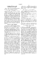
FIG. 1 is a perspective view of the one-piece combined wall mount and electrical box unit located relative to a wall onto which it is to be mounted;

FIG. 2 is a front elevational view of the combined wall mount and electrical outlet box unit;

FIG. 3 is a cross sectional view taken substantially along lines 3--3 of FIG. 2;

FIG. 4 is a cross sectional view taken substantially along lines 4--4 of FIG. 2;

FIG. 5 is a rear elevational view of the combined wall mount and electrical outlet box unit;

FIG. 6 is an enlarged fragmentary cross sectional view taken substantially along line 6--6 of FIG. 5 and showing the manner in which the back plate is secured to the rear side of the combined wall mount and electrical outlet box unit; and

FIG. 7 is front elevational view of a modified embodiment of the combined wall mount and electrical outlet box unit.

BACKGROUND OF THE INVENTION

The present invention relates to a combined wall mount and electrical outlet box unit.

By way of background, in the past wall mounts having the general outer configuration shown in FIG. 1 of the drawings were supplied with a solid front wall having score marks thereon. In use, the installer had to cut out an opening in the shape of the perimeter of the electrical outlet box from the front wall. However, this was a time-consuming and tedious task because the wall mounts were fabricated of tough polyethylene plastic or metal. Thereafter, a separate conventional electric outlet box was slid into the opening which was cut out in the wall mount. This outlet box was of conventional shape, and, as noted above, it had an outer perimeter which was the size of the opening which was cut into the face of the wall mount. There were no connections between the wall mount and the electrical outlet box other than the contact therebetween at the cutout portion in the face of the wall mount.

SUMMARY OF THE INVENTION

It is one object of the present invention to provide a combined wall mount and electrical outlet box unit wherein the electrical outlet box is an integral portion of the wall mount, thereby obviating the necessity to cut the front wall of the wall mount for receiving an electrical outlet unit box.

Another object of the present invention is to provide a combined wall mount and electrical outlet box unit wherein the electrical outlet box portion is much larger than the separate outlet box which was previously installed into the separate wall mount.

A further object of the present invention is to provide an improved one-piece wall mount and electrical outlet box unit wherein the electrical outlet box portion is firmly secured to the wall mount because it is an integral molded part thereof.

Yet another object of the present invention is to provide a combined wall mount and electrical outlet box unit which has a rear wall which is flush with the mounting flange thereof and which serves as an enclosing portion of the electrical outlet box. Other objects and attendant advantages of the present invention will readily be perceived hereafter.

The present invention relates to a combined wall mount and electrical outlet box unit for mounting on a surface comprising a housing, a plurality of opposed side walls on said housing, inner and outer sides on said side walls, inner and outer edges on said side walls, a front wall connected to said outer edges of each of said side walls and extending inwardly therefrom toward other outer edges of said opposed side walls, mounting flange means connected to said inner edges of said side walls and extending outwardly therefrom away from said outer sides of said side walls for securing said unit on a surface, an opening in said front wall, box means defining a chamber for receiving wires, front and rear edges on said box means, said front edges being secured to said front wall with said chamber being accessible through said opening, said rear edges of said side walls defining a second opening, a plate secured across said second opening, and third openings in said plate for receiving wires which pass into said chamber defined by said box means.

The various aspects of the present invention will be more fully understood when the following portions of the specification are read in conjunction with the accompanying drawings wherein:

This is a continuation, of application Ser. No. 08/241,764 filed May 12, 1994 now U.S. Pat. No. 5,578,791.

Citations de brevets
Brevet cité Date de dépôt Date de publication Déposant Titre
US14840012 janv. 192219 févr. 1924Ainsworth George RFixture-hanging device
US18982824 janv. 192921 févr. 1933Edward L. KappelmanOutlet box
US370183718 mars 197131 oct. 1972H. H. Robertson, A Corp. Of DelawareMultiple electrical service underfloor access housing
US413533712 sept. 197723 janv. 1979Medlin; Lewis B.Mounting means for electric outlet box
US416719621 oct. 197711 sept. 1979Acorn Engineering Co.Vandal-proof plumbing valve access box
US422209314 févr. 19799 sept. 1980Devine Lighting, IncorporatedLight mounting fixture assembly
US43237234 avr. 19806 avr. 1982H. H. Robertson CompanySurface mounted outlet unit
US463516817 juin 19856 janv. 1987Crowley; Charles H.Light fixture mounting pedestal and method of installing same
US472428116 juin 19869 févr. 1988Kullberg; William D.Electrical junction or outlet box
US472615224 nov. 198623 févr. 1988Vagedes Industries, Inc.Bracket for mounting a fixture on a wall
US49207085 mai 19891 mai 1990Tapco Products Company, Inc.Wall mounting assembly
US492070911 avr. 19891 mai 1990Webb Mfg., Inc.J-channel member for siding
US492205610 févr. 19881 mai 1990Network Communications, Inc.Surface mounted box
US50004094 déc. 198919 mars 1991Tapco Products Company, Inc.One piece wall mounting bracket
US517732520 déc. 19895 janv. 1993A. J. Giammanco & Associates, Inc.Housing for electric transformer
US528766531 mars 199222 févr. 1994Rath, Jr.; RobertWaterproof flanged exterior wall outlet secured to a building framework
US530725423 oct. 199226 avr. 1994The Genlyte Group IncorporatedLight fixture with detachable rear mounting box
US535088426 oct. 199227 sept. 1994Thomas & Betts International, Inc.Exhibition hall electrical floor box
US539709318 avr. 199414 mars 1995Mid-America Building Products CorporationWall mounting assembly
US54480118 avr. 19935 sept. 1995Erico International CorporationLow voltage mounting plate and method of installation
US548665015 nov. 199323 janv. 1996Hubbell IncorporatedPartition for dividing a device box
Citations hors brevets
Référence
1Brochure entitled "The Mid America Master Series"--16 pages (Copyright 1994).
2Brochure entitled The Mid America Master Series 16 pages (Copyright 1994).
3Brochure entitled Zip Box Blue Nonmetallic Switch and Outlet Boxes 18 pages, Carlon 1992.
4Brochure entitled"Zip Box Blue Nonmetallic Switch and Outlet Boxes" 18 pages,
Référencé par
Brevet citant Date de dépôt Date de publication Déposant Titre
US613352422 avr. 199917 oct. 2000Boss Products CorporationCombined wall mount and electrical outlet box
US630385828 août 200016 oct. 2001Bosse, Jr. John J.Combined wall mount and electrical outlet box
US631028729 juin 199930 oct. 2001Tapco International CorporationElectrical block
US635922021 févr. 200119 mars 2002Allen Clyde D.Electrical block
US641744710 oct. 20019 juil. 2002Boss Products CorporationCombined wall mount and electrical outlet box
US642937128 mars 20016 août 2002Tapco International CorporationElectrical block
US672392124 sept. 200220 avr. 2004Bluegrass Products, LlcExterior mounting block for electrical fixtures
US682541410 sept. 200330 nov. 2004Bluegrass Products, L.L.C.Exterior mounting block for electrical fixtures
US711582020 juil. 20053 oct. 2006Arlington Industries, Inc.Recessed outlet box retrofit siding construction
US731919219 déc. 200615 janv. 2008Arlington Industries, Inc.Frame member and box combination for recessing an electrical box and cover assembly