US5921981A - Multi-spot laser surgery - Google Patents
Multi-spot laser surgery Download PDFInfo
- Publication number
- US5921981A US5921981A US08/556,204 US55620495A US5921981A US 5921981 A US5921981 A US 5921981A US 55620495 A US55620495 A US 55620495A US 5921981 A US5921981 A US 5921981A
- Authority
- US
- United States
- Prior art keywords
- laser
- simultaneous
- optical fiber
- beams
- source
- Prior art date
- Legal status (The legal status is an assumption and is not a legal conclusion. Google has not performed a legal analysis and makes no representation as to the accuracy of the status listed.)
- Expired - Lifetime
Links
Images


Classifications
-
- A—HUMAN NECESSITIES
- A61—MEDICAL OR VETERINARY SCIENCE; HYGIENE
- A61F—FILTERS IMPLANTABLE INTO BLOOD VESSELS; PROSTHESES; DEVICES PROVIDING PATENCY TO, OR PREVENTING COLLAPSING OF, TUBULAR STRUCTURES OF THE BODY, e.g. STENTS; ORTHOPAEDIC, NURSING OR CONTRACEPTIVE DEVICES; FOMENTATION; TREATMENT OR PROTECTION OF EYES OR EARS; BANDAGES, DRESSINGS OR ABSORBENT PADS; FIRST-AID KITS
- A61F9/00—Methods or devices for treatment of the eyes; Devices for putting-in contact lenses; Devices to correct squinting; Apparatus to guide the blind; Protective devices for the eyes, carried on the body or in the hand
- A61F9/007—Methods or devices for eye surgery
- A61F9/008—Methods or devices for eye surgery using laser
-
- A—HUMAN NECESSITIES
- A61—MEDICAL OR VETERINARY SCIENCE; HYGIENE
- A61B—DIAGNOSIS; SURGERY; IDENTIFICATION
- A61B3/00—Apparatus for testing the eyes; Instruments for examining the eyes
- A61B3/10—Objective types, i.e. instruments for examining the eyes independent of the patients' perceptions or reactions
- A61B3/13—Ophthalmic microscopes
- A61B3/135—Slit-lamp microscopes
-
- A—HUMAN NECESSITIES
- A61—MEDICAL OR VETERINARY SCIENCE; HYGIENE
- A61F—FILTERS IMPLANTABLE INTO BLOOD VESSELS; PROSTHESES; DEVICES PROVIDING PATENCY TO, OR PREVENTING COLLAPSING OF, TUBULAR STRUCTURES OF THE BODY, e.g. STENTS; ORTHOPAEDIC, NURSING OR CONTRACEPTIVE DEVICES; FOMENTATION; TREATMENT OR PROTECTION OF EYES OR EARS; BANDAGES, DRESSINGS OR ABSORBENT PADS; FIRST-AID KITS
- A61F9/00—Methods or devices for treatment of the eyes; Devices for putting-in contact lenses; Devices to correct squinting; Apparatus to guide the blind; Protective devices for the eyes, carried on the body or in the hand
- A61F9/007—Methods or devices for eye surgery
- A61F9/008—Methods or devices for eye surgery using laser
- A61F9/00821—Methods or devices for eye surgery using laser for coagulation
-
- A—HUMAN NECESSITIES
- A61—MEDICAL OR VETERINARY SCIENCE; HYGIENE
- A61B—DIAGNOSIS; SURGERY; IDENTIFICATION
- A61B18/00—Surgical instruments, devices or methods for transferring non-mechanical forms of energy to or from the body
- A61B18/18—Surgical instruments, devices or methods for transferring non-mechanical forms of energy to or from the body by applying electromagnetic radiation, e.g. microwaves
- A61B18/20—Surgical instruments, devices or methods for transferring non-mechanical forms of energy to or from the body by applying electromagnetic radiation, e.g. microwaves using laser
- A61B18/22—Surgical instruments, devices or methods for transferring non-mechanical forms of energy to or from the body by applying electromagnetic radiation, e.g. microwaves using laser the beam being directed along or through a flexible conduit, e.g. an optical fibre; Couplings or hand-pieces therefor
- A61B2018/2205—Characteristics of fibres
- A61B2018/2211—Plurality of fibres
-
- A—HUMAN NECESSITIES
- A61—MEDICAL OR VETERINARY SCIENCE; HYGIENE
- A61F—FILTERS IMPLANTABLE INTO BLOOD VESSELS; PROSTHESES; DEVICES PROVIDING PATENCY TO, OR PREVENTING COLLAPSING OF, TUBULAR STRUCTURES OF THE BODY, e.g. STENTS; ORTHOPAEDIC, NURSING OR CONTRACEPTIVE DEVICES; FOMENTATION; TREATMENT OR PROTECTION OF EYES OR EARS; BANDAGES, DRESSINGS OR ABSORBENT PADS; FIRST-AID KITS
- A61F9/00—Methods or devices for treatment of the eyes; Devices for putting-in contact lenses; Devices to correct squinting; Apparatus to guide the blind; Protective devices for the eyes, carried on the body or in the hand
- A61F9/007—Methods or devices for eye surgery
- A61F9/008—Methods or devices for eye surgery using laser
- A61F2009/00861—Methods or devices for eye surgery using laser adapted for treatment at a particular location
- A61F2009/00863—Retina
Definitions
- This invention relates to laser ophthalmic surgery and more particularly to a method and system particularly suited to panretinal photocoagulation procedures performed on a human patient.
- Photocoagulation has been used for various ophthalmic procedures such as panretinal photocoagulation (PRP) and the like. Such procedures are performed using either a slit-lamp (SL) laser delivery system or, when surgical intervention is required, endo-ocular laser probes.
- PRP panretinal photocoagulation
- SL slit-lamp
- the imaging optics are used in conjunction with a variety of contact lenses, and must be capable of focusing the output end (distal) of the fiber onto the retina.
- the focal length of the imaging optics is typically variable, i.e. zoom, to magnify the size of the fiber's image on the retina from 1 to 20 times, corresponding to 50-1000 microns on the retina.
- the area affected may include the entire retina outside the foveal region.
- PRP panretinal photocoagulation
- the accepted mode of treatment is to lay down an uniform distribution of photocoagulative burns, with spot sizes of 250-500 microns and spaced at 1 times the spot diameter. A typical treatment consist of 1600 burns.
- the time to position the spot and deliver the laser energy depends on the features of the SL and the skill of the surgeon and is typically 2 seconds per spot. This means that the treatment time is in excess of 60 minutes which is fatiguing to the patient and surgeon. Also, laying down a uniform pattern is difficult and the pattern is typically more random than a geometric in distribution.
- the SL is not used. Instead standard endoocular laser probes are employed. The treatment objectives are the same, however, to lay down a pattern of photocoagulative burns in the affected area. Using the endo-laser probe, the surgeon holds the distal tip close to the retina and lays down 1500-2000 spots, 500 microns in diameter. This procedure can take more than one hour. Using the probe close to the retina increases the risk of accidental tears and the length of the procedure prolongs the anesthesia time in high risk patient groups.
- Another object is the provision of such an apparatus and method which significantly reduces the time required for such operations.
- a third object is the provision of such an apparatus and method which is readily usable with existing equipment.
- a fourth object is the provision of such an apparatus and method which provides increased accuracy.
- a fifth object is the provision of such an apparatus and method which provides a more repeatable pattern of laser spots or burns.
- a method of performing an ophthalmic surgical procedure such as panretinal photocoagulation on a human patient includes the steps of:
- a multi-spot slit-lamp system for performing an ophthalmic surgical procedure such as panretinal photocoagulation on a human patient includes a source of illumination light, a laser source for generating a single beam of laser energy, and an optical system for directing the illumination light along an optical path to the eye of a patient to be treated.
- Structure is provided for splitting the single beam of laser energy into a plurality of simultaneous laser beams.
- the splitting structure has a distal end through which exit the simultaneous laser beams into the optical path of the illumination light. It is preferred that the simultaneous laser beams be generally parallel to each other and have a size suitable for performing the ophthalmic surgical procedure on a human patient.
- a handpiece having a distal end sized to fit inside the eye of a human patient for purposes of performing the ophthalmic surgical procedure is optically connected to the laser source connector by an optical fiber cable extending from the proximal connector to the handpiece.
- Structure for splitting the single beam of laser energy into a plurality of simultaneous laser beams is disposed between the laser source and the distal end of the handpiece so that the simultaneous laser beams exit from the distal end of the handpiece in a predetermined distribution.
- the simultaneous laser beams upon exiting from the distal end of the handpiece have a size suitable for performing said ophthalmic surgical procedure on a human patient.
- FIG. 1 is a perspective view of a slit-lamp laser system incorporating the present invention
- FIG. 2 is a simplified illustration of the optics of the system of FIG. 1;
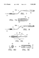
- FIG. 3 is an elevation of an optical fiber cable used in the system of FIG. 1;
- FIG. 3A is a cross-sectional view of a proximal connector of the optical fiber cable of FIG. 3;
- FIG. 3B is an end view of the distal connector of the optical fiber cable of FIG. 3;
- FIG. 4 is an elevation of an alternative embodiment of the optical fiber cable used in the system of FIG. 1;
- FIG. 4A is an end view of a distal connector of the optical fiber cable of FIG. 4, with parts removed for clarity;
- FIG. 4B is an end view similar to FIG. 4A with the removed parts reinserted;
- FIG. 4C is a longitudinal sectional view of the distal connector of the optical fiber cable of FIG. 4;
- FIG. 5 is an elevation of a third embodiment of the optical fiber cable used in the system of FIG. 1;
- FIG. 5A is an enlarged view with parts broken away for clarity of the optical fiber cable of FIG. 5;
- FIG. 5B is an end view of the distal connector of the optical fiber cable of FIG. 5;
- FIG. 6 is an elevation of a laser probe of the present invention adapted for ophthalmic surgical procedures such as panretinal photocoagulation;
- FIG. 6A is a cross sectional view of the proximal connector of the laser probe of FIG. 6;
- FIG. 6B is a distal end view of the probe of FIG. 6, with parts removed for clarity;
- FIG. 6C is a cross sectional view of the distal end of the probe of FIG. 6;
- FIG. 7 is an elevation of an alternative embodiment of the laser probe of FIG. 6;
- FIG. 7A is a cross sectional view of the distal end of the probe of FIG. 7;
- FIG. 8 is an elevation of a third embodiment of the laser probe of FIG. 6;
- FIG. 8A is an enlarged view of a portion of the probe of FIG. 8;
- FIG. 8B is a distal end view of the probe of FIG. 8, with parts removed for clarity;
- FIG. 8C is a cross sectional view of the distal end of the probe of FIG. 8;
- the ophthalmic operation is performed using a slit-lamp apparatus, such as that shown in FIGS. 1 and 2.
- the physician performing such an operation uses such apparatus to control the application (and intensity) of illuminating light and the application (and intensity) of laser energy to the treatment/operative site.
- such apparatus includes an optical fiber device 3 for transmitting a laser beam coming from a laser source, and a second optical fiber device 5 for transmitting the illumination light from a light source.
- a lens holder unit 6 is provided for accommodating therein a lens system for transmitting the laser beam and the illumination light to the patient's eye 10.
- the optical system includes an ophthalmoscope lens 11 for magnifying the image of the fundus oculi of the patient's eye. This image is thereby provided to the eye 12 of the physician.
- the optical system includes a focusing lens L1 for the illumination light and a perforated mirror M1. These two components are arranged such that the laser beam travels generally along the optical path of the illumination light. (As will become apparent, the laser beam at this point is actually a composite beam, and it is the composite beam which travels along the optical path defined by the optics discussed below to the patient's eye.) It is possible to use a half mirror or a dichroic mirror in place of the perforated mirror M1.
- the laser beam and the illumination light coaxial therewith are projected on the patient's eye by mean of a projection lens L2.
- the size of the spot of the laser beam imaging on the fundus oculi is changed by moving the projection lens L2 in the direction of optical axis.
- a mirror M2 is housed in the aforementioned lens holder unit 6 together with the aforementioned lens L1 and the mirror M1.
- a filter F for protecting the physician's eye 12 is adapted to be placed out of the path of light during the observation and the sighting, but is moved into the path of light in advance of the laser operation.
- a lens L3 is used for observing the image of the patient's eye.
- FIG. 1 shows a slit-lamp in combination with a binocular indirect ophthalmoscope for permitting a switching of the laser beam.
- a laser source housing 41 encases a laser tube, a laser control system and so forth.
- the binocular indirect ophthalmoscope 42 is mounted on a carrier 43.
- a slit-lamp 44 is adapted to be moved up and down by means of a slit table 45.
- change-over switches 46 and a control box 47 are provided, control box 47 controlling various conditions such as, for example, coagulation time, coagulation power and spot size of the laser beam.
- Optical cables 48, 49 for the laser beam are connected to ophthalmoscope 42 and to the slitlamp 44 respectively.
- a foot switch device 50 has two pedals for triggering the optical coagulation and for triggering the vertical movement of the slit table 45 respectively. It should be understood that also the slit-lamp system is shown and described in some detail, the present invention is not limited to any particular slit-lamp system.
- optical fiber cable 48 be a multiple-fiber assembly, with the result that multiple spots can be imaged onto the treatment area. Moreover, the spacing of the fibers can be optimized to yield a more uniform geometric pattern.
- the surgeon using the system of FIGS. 1 and 2 can position the multi-spot pattern using the low power aiming beam and deliver the photocoagulative laser pulse.
- the time to position the multi-spot pattern is the same as the single spot procedure used in the prior art. However, the total treatment time is reduced by the number of spots in the pattern. As an example, if four (4) spots (as indicated in FIG. 3 by the four separate optical fibers 23) are used the treatment time is potentially reduced to one fourth the standard time.
- Optical fiber cable 48 is constructed of four fibers 23 connected to the laser source via a proximal connector 25 (input end) and to the slit-lamp imaging optics described above via a distal connector 27 (output end).
- the size of the fiber is chosen for the highest core to cladding diameter ratio for optimum energy collection at the proximal end.
- the maximum size of the fiber is governed by the magnification range of the imaging optics in the slit-lamp and the desired spot size on the retina. Magnification ranges for standard SL imaging optics are 1:1 to 20:1. If the fibers selected are 200 microns in diameter, the imaging size on the retina would vary from 200-4000 microns. For PRP procedures, the surgeon typically uses a 500 micron spot.
- a lens 29 is provided in the optical path in the proximal connector.
- the lens shown is a ball lens; however, other types of focusing elements could be used.
- a star spacer 31 is used at the distal end of distal connector 27 to provide a uniform spacing of two (2) times the spot diameter.
- the spacer can be metallic, ceramic, etc., or the fibers can be held in spaced relationship in an epoxy matrix material.
- an alternative optical cable assembly 48A for use with a slit-lamp assembly is shown.
- cable 48A there is a single fiber 33 optically connected to the laser source via proximal connector 25 (input end) and to the slit lamp imaging optics via distal connector 27 (output end).
- the proximal end of fiber 33 is a standard polished end fiber with no additional lenses.
- the distal end contains a microlens array 35 with four elements to produce four spots.
- a collimating lens 37 provides uniform light energy to the microlens array.
- the size of the fiber is chosen for the optimum energy collection at the distal end of the fiber.
- the lenses shown are a ball lens and a 4-element microlens array; however, other types of focusing elements could be used.
- the single laser beam transmitted by fiber 33 is collimated by lens 37 and split into four simultaneous parallel laser beams by microlens array 35 for application through the slit-lamp apparatus to the patient.
- cable 48B another alternative construction of cable 48, labeled 48B, is illustrated.
- the single laser beam from the source is split using fiber splitters.
- cable 48B has a single optical fiber 33 connected to the laser source via proximal connector 25, which is multiplexed by means of a 1 ⁇ 4 multimode coupler 39 into four fibers 23 at the distal end.
- the proximal end is a standard polished end fiber with no additional lenses.
- the single fiber is multiplexed into four fibers via three 1:2 fiber splitters (disposed in a configuration such as that shown in FIG. 8A).
- the actual method of splitting may be varied as desired.
- the maximum size of the fiber is governed by the magnification range of the imaging optics in the slit lamp and the desired spot size on the retina. Magnification ranges for standard SL imaging optics are 1:1 to 20:1. If the fibers selected are 200 microns in diameter, the imaging size on the retina would vary from 200-4000 microns, as desired by the physician. Star spacer 31 is preferably used at the distal end to provide the desired spacing between the spots by holding the fibers 23 in fixed geometrical relationship.
- FIGS. 1 and 2 As discussed above, when PRP treatment requires surgical intervention, the slit-lamp assembly of FIGS. 1 and 2 is not used. Rather endo-ocular laser probes such as those shown in FIGS. 6-8 are utilized. The optical constructions of these probes are very similar to the optical cable constructions discussed above. Rather than a distal connector, however, such probes have a handpiece 51, generally terminating in a distal needle 53.
- multiple spots are imaged onto the treatment area.
- the spacing of the fibers (and/or beams) can be optimized to yield a more uniform geometric pattern than is available with conventional equipment.
- the surgeon can position the multi-spot pattern using the low power aiming beam and deliver the photocoagulative laser pulse.
- the time to position the multi-spot pattern is generally the same as the single spot procedure, but the total treatment time is reduced by the number of spots in the pattern, similar to the reduction discussed above in connection with the slit-lamp system.
- a probe 53 is constructed of four fibers 23 connected to the laser source via proximal connector 25. Fibers 23 run the entire length of probe 53 and terminate distally in handpiece 51. The size of the fibers is chosen for the highest core to clad diameter ratio for optimum energy collection at the proximal end. To insure uniform input of laser energy into the fibers, lens 29 is provided at the proximal end. Although the lens shown is a ball lens, other types of focusing elements could be used. Star spacer 31 is used at the distal end to provide the desired spacing of the fibers and to hold them in fixed geometrical relationship. A collimating lens 37 and/or a focusing lens 57 are preferably disposed distally of the fibers 23 to more accurately direct the resulting simultaneous laser beams.
- FIG. 7 an alternative embodiment 53A of the laser probe is shown.
- the probe uses a single fiber 33 connected to the laser source via proximal connector, which fiber continues to the distal needle end of handpiece 51.
- the proximal end of fiber 33 is a standard polished end fiber with no additional lenses.
- the distal end terminates at a microlens array 35 having four elements to produce four spots at a distance to minimize risk of retinal tears.
- a collimating lens 37 provides uniform light energy to the microlens array.
- the lenses shown here are a ball lens and a 4-element microlens array, however, other types of focusing elements could be used.
- a third embodiment 53B of the laser probe is shown.
- a single fiber 33 is connected to the laser source via proximal connector 25 and is multiplexed by a 1 ⁇ 4 multimode coupler 39 into four fibers 23 at the distal end.
- the proximal end is a standard polished end fiber with no additional lenses.
- Inside the multimode coupler the single fiber is multiplexed into four fiber via three 1:2 fiber splitters 61, or by any other suitable method.
- the size of the spot and spot spacing vary proportionally with the distance from the distal tip to the retina.
- a star spacer 31 is used at the distal end to suitably space fibers 23.
- a collimating lens 37 and a focusing lens 57 may be provided distally to suitably focus the simultaneous laser beams at a distance from the distal end of the handpiece needle to help avoid the possibility of retinal tears.
- the present invention does not depend on the particular type of laser being used, although the materials making up the optical fibers could be optimized for particular laser types. It is desired, however, that if practicable the optical fibers be chosen to have an optimum core to clad ratio.
- Various lens types such as Gradient-Index (GRIN), ball diffractive, holographic, microlenslets, or any combination thereof may be used without changing the underlying invention.
- GRIN Gradient-Index
- ball diffractive ball diffractive
- holographic holographic
- microlenslets or any combination thereof may be used without changing the underlying invention.
- the invention has been described in connection with ophthalmic surgery, and in particular in connection with PRP, it should be understood that the invention may also have application to other procedures such as corneal ablation and/or cutting and dermatology.
Abstract
Description
Claims (15)
Priority Applications (7)
| Application Number | Priority Date | Filing Date | Title |
|---|---|---|---|
| US08/556,204 US5921981A (en) | 1995-11-09 | 1995-11-09 | Multi-spot laser surgery |
| JP9518398A JP2000500043A (en) | 1995-11-09 | 1996-11-08 | Multi-spot laser surgery device |
| PCT/US1996/018167 WO1997017011A1 (en) | 1995-11-09 | 1996-11-08 | Multi-spot laser surgery |
| AU77295/96A AU7729596A (en) | 1995-11-09 | 1996-11-08 | Multi-spot laser surgery |
| EP96940405A EP0929255A4 (en) | 1995-11-09 | 1996-11-08 | Multi-spot laser surgery |
| US09/124,126 US6096028A (en) | 1995-11-09 | 1998-07-29 | Multi-slot laser surgery |
| US09/241,208 US6066128A (en) | 1995-11-09 | 1999-02-01 | Multi-spot laser surgery |
Applications Claiming Priority (1)
| Application Number | Priority Date | Filing Date | Title |
|---|---|---|---|
| US08/556,204 US5921981A (en) | 1995-11-09 | 1995-11-09 | Multi-spot laser surgery |
Related Child Applications (2)
| Application Number | Title | Priority Date | Filing Date |
|---|---|---|---|
| US09/124,126 Continuation-In-Part US6096028A (en) | 1995-11-09 | 1998-07-29 | Multi-slot laser surgery |
| US09/241,208 Division US6066128A (en) | 1995-11-09 | 1999-02-01 | Multi-spot laser surgery |
Publications (1)
| Publication Number | Publication Date |
|---|---|
| US5921981A true US5921981A (en) | 1999-07-13 |
Family
ID=24220326
Family Applications (3)
| Application Number | Title | Priority Date | Filing Date |
|---|---|---|---|
| US08/556,204 Expired - Lifetime US5921981A (en) | 1995-11-09 | 1995-11-09 | Multi-spot laser surgery |
| US09/124,126 Expired - Fee Related US6096028A (en) | 1995-11-09 | 1998-07-29 | Multi-slot laser surgery |
| US09/241,208 Expired - Fee Related US6066128A (en) | 1995-11-09 | 1999-02-01 | Multi-spot laser surgery |
Family Applications After (2)
| Application Number | Title | Priority Date | Filing Date |
|---|---|---|---|
| US09/124,126 Expired - Fee Related US6096028A (en) | 1995-11-09 | 1998-07-29 | Multi-slot laser surgery |
| US09/241,208 Expired - Fee Related US6066128A (en) | 1995-11-09 | 1999-02-01 | Multi-spot laser surgery |
Country Status (5)
| Country | Link |
|---|---|
| US (3) | US5921981A (en) |
| EP (1) | EP0929255A4 (en) |
| JP (1) | JP2000500043A (en) |
| AU (1) | AU7729596A (en) |
| WO (1) | WO1997017011A1 (en) |
Cited By (44)
| Publication number | Priority date | Publication date | Assignee | Title |
|---|---|---|---|---|
| US6066128A (en) * | 1995-11-09 | 2000-05-23 | Alcon Laboratories, Inc. | Multi-spot laser surgery |
| WO2001037769A1 (en) | 1999-11-22 | 2001-05-31 | Yaakov Amitai | Treating a target with a divided laser beam |
| WO2001041266A1 (en) * | 1999-12-06 | 2001-06-07 | Candela Corporation | Multipulse dye laser |
| US6331177B1 (en) | 1998-04-17 | 2001-12-18 | Visx, Incorporated | Multiple beam laser sculpting system and method |
| US6364872B1 (en) | 1999-12-06 | 2002-04-02 | Candela Corporation | Multipulse dye laser |
| DE10100859A1 (en) * | 2001-01-11 | 2002-08-14 | Zeiss Carl Jena Gmbh | Medical laser therapy device |
| US20030125718A1 (en) * | 1998-04-17 | 2003-07-03 | Visx, Incorporated | Multiple beam laser sculpting system and method |
| US6872202B2 (en) | 2001-01-11 | 2005-03-29 | Carl Zeiss Jena Gmbh | Laser slit lamp with laser radiation source |
| WO2005065116A2 (en) | 2003-12-24 | 2005-07-21 | The Board Of Trustees Of The Leland Stanford Junior University | Patterned laser treatment of the retina |
| US20050288745A1 (en) * | 2004-06-28 | 2005-12-29 | Andersen Dan E | Method and device for optical ophthalmic therapy |
| US20050286019A1 (en) * | 2004-06-10 | 2005-12-29 | Wiltberger Michael W | Scanning ophthalmic fixation method and apparatus |
| US20070027509A1 (en) * | 2005-07-29 | 2007-02-01 | Eisenberg Elliot S | Automated panretinal laser photocoagulation |
| US20070121069A1 (en) * | 2005-11-16 | 2007-05-31 | Andersen Dan E | Multiple spot photomedical treatment using a laser indirect ophthalmoscope |
| US20070126985A1 (en) * | 2005-10-28 | 2007-06-07 | Wiltberger Michael W | Photomedical treatment system and method with a virtual aiming device |
| US20070129709A1 (en) * | 2005-12-01 | 2007-06-07 | Andersen Dan E | System and method for minimally traumatic ophthalmic photomedicine |
| US20070265602A1 (en) * | 2006-03-24 | 2007-11-15 | Mordaunt David H | Multi-spot optical fiber endophotocoagulation probe |
| US20070299430A1 (en) * | 2004-11-02 | 2007-12-27 | Lenticular Research Group Llc | Apparatus and processes for preventing or delaying one or more symptoms of presbyopia |
| US20080033406A1 (en) * | 2006-04-28 | 2008-02-07 | Dan Andersen | Dynamic optical surgical system utilizing a fixed relationship between target tissue visualization and beam delivery |
| WO2008024848A2 (en) * | 2006-08-22 | 2008-02-28 | Synergetics, Inc. | Multiple target laser probe |
| US20080051770A1 (en) * | 2006-08-22 | 2008-02-28 | Synergetics, Inc. | Multiple Target Laser Probe |
| US20080108981A1 (en) * | 2006-11-03 | 2008-05-08 | William Telfair | Shaped tip illuminating laser probe treatment apparatus |
| US20080161781A1 (en) * | 2005-02-19 | 2008-07-03 | Mcardle George J | Apparatus and Processes For Preventing or Delaying Onset or Progression of Age-Related Cataract |
| US20080165323A1 (en) * | 2007-01-05 | 2008-07-10 | Eisenberg Elliot S | Panretinal laser fundus contact lens |
| US20080319427A1 (en) * | 2007-03-13 | 2008-12-25 | Palanker Daniel V | Computer guided patterned laser trabeculoplasty |
| US20090015923A1 (en) * | 2007-07-09 | 2009-01-15 | Auld Jack R | Multi-Spot Ophthalmic Laser Probe |
| US20100318074A1 (en) * | 2009-06-10 | 2010-12-16 | Bruno Dacquay | Ophthalmic endoillumination using low-power laser light |
| US20110122366A1 (en) * | 2009-11-24 | 2011-05-26 | Smith Ronald T | Single-fiber multi-spot laser probe for ophthalmic endoillumination |
| US20110144627A1 (en) * | 2009-12-15 | 2011-06-16 | Smith Ronald T | Multi-spot laser probe |
| US20120191078A1 (en) * | 2011-01-21 | 2012-07-26 | Yadlowsky Michael J | Combined surgical endoprobe for optical coherence tomography, illumination or photocoagulation |
| US20130077917A1 (en) * | 2011-09-23 | 2013-03-28 | Bruno Lassalas | Shaping laser beam launches into optical fibers to yield specific output effects |
| US8571364B2 (en) | 2011-11-09 | 2013-10-29 | Alcon Research, Ltd. | Multi-spot laser probe with faceted optical element |
| US8613741B1 (en) | 2006-10-11 | 2013-12-24 | Candela Corporation | Voltage bucking circuit for driving flashlamp-pumped lasers for treating skin |
| US9844318B2 (en) | 2013-03-26 | 2017-12-19 | Novartis Ag | Devices, systems, and methods for calibrating an OCT imaging system in a laser surgical system |
| US9849034B2 (en) | 2011-11-07 | 2017-12-26 | Alcon Research, Ltd. | Retinal laser surgery |
| US10179071B2 (en) | 2005-09-19 | 2019-01-15 | Topcon Medical Laser Systems, Inc. | System and method for generating treatment patterns |
| US10245181B2 (en) | 2012-12-21 | 2019-04-02 | Alcon Research, Ltd. | Grin fiber multi-spot laser probe |
| US10463540B2 (en) | 2013-12-23 | 2019-11-05 | Quantel Medical, Inc. | System and device for multi spot photocoagulation |
| US20200352433A1 (en) * | 2016-06-30 | 2020-11-12 | Iridex Corporation | Handheld Ophthalmic Laser System With Replaceable Contact Tips and Treatment Guide |
| US11135092B2 (en) | 2017-12-12 | 2021-10-05 | Alcon Inc. | Multi-core fiber for a multi-spot laser probe |
| US11213426B2 (en) * | 2017-12-12 | 2022-01-04 | Alcon Inc. | Thermally robust multi-spot laser probe |
| US11291470B2 (en) | 2017-12-12 | 2022-04-05 | Alcon Inc. | Surgical probe with shape-memory material |
| US11385401B2 (en) | 2019-12-04 | 2022-07-12 | Alcon Inc. | Multi-core optical fiber with reduced bubble formation |
| WO2022234521A1 (en) * | 2021-05-07 | 2022-11-10 | Alcon Inc. | Surgical laser system with illumination |
| US11779427B2 (en) | 2017-12-12 | 2023-10-10 | Alcon Inc. | Multiple-input-coupled illuminated multi-spot laser probe |
Families Citing this family (73)
| Publication number | Priority date | Publication date | Assignee | Title |
|---|---|---|---|---|
| DE19814095C2 (en) * | 1998-03-30 | 2003-08-14 | Zeiss Carl Jena Gmbh | Method and arrangement for checking and controlling the treatment parameters on an ophthalmic treatment device |
| JP4038350B2 (en) * | 2001-05-01 | 2008-01-23 | 株式会社ニデック | Ophthalmic laser treatment device |
| WO2004000098A2 (en) | 2002-06-19 | 2003-12-31 | Palomar Medical Technologies, Inc. | Method and apparatus for treatment of cutaneous and subcutaneous conditions |
| AUPS313802A0 (en) * | 2002-06-25 | 2002-07-18 | Riancorp Pty Ltd | Laser beam homogenisers in medical applications |
| US6786628B2 (en) * | 2002-07-03 | 2004-09-07 | Advanced Medical Optics | Light source for ophthalmic use |
| US7740600B2 (en) * | 2002-08-02 | 2010-06-22 | Candela Corporation | Apparatus and method for inhibiting pain signals transmitted during a skin related medical treatment |
| EP1558189A4 (en) * | 2002-10-17 | 2008-01-23 | Iridex Corp | Laser delivery device incorporating a plurality of laser source optical fibers |
| JP2007526013A (en) | 2003-06-16 | 2007-09-13 | ソルクス インコーポレイテッド | Shunt device for treating glaucoma |
| US20060069340A1 (en) * | 2003-06-16 | 2006-03-30 | Solx, Inc. | Shunt for the treatment of glaucoma |
| US7189226B2 (en) * | 2003-07-28 | 2007-03-13 | Synergetics, Inc. | Coaxial illuminated laser endoscopic probe and active numerical aperture control |
| US20050075628A1 (en) * | 2003-10-02 | 2005-04-07 | Karl Cazzini | Variable intensity wide-angle illuminator |
| DE10358927B4 (en) * | 2003-12-16 | 2021-09-09 | Carl Zeiss Meditec Ag | Laser device and method for material processing by means of laser radiation |
| US7856985B2 (en) * | 2005-04-22 | 2010-12-28 | Cynosure, Inc. | Method of treatment body tissue using a non-uniform laser beam |
| US20060287662A1 (en) * | 2005-05-26 | 2006-12-21 | Ntk Enterprises, Inc. | Device, system, and method for epithelium protection during cornea reshaping |
| US10488606B2 (en) | 2005-09-19 | 2019-11-26 | Topcon Medical Laser Systems, Inc. | Optical switch and method for treatment of tissue |
| US10617564B1 (en) | 2006-05-10 | 2020-04-14 | Apple Inc. | Area scanning photomedicine device and method |
| US7586957B2 (en) | 2006-08-02 | 2009-09-08 | Cynosure, Inc | Picosecond laser apparatus and methods for its operation and use |
| US20080082087A1 (en) * | 2006-09-19 | 2008-04-03 | Eisenberg Elliott S | Fast panretinal laser photocoagulation |
| US8603081B2 (en) * | 2007-08-23 | 2013-12-10 | Ntk Enterprises, Inc. | System and method for defining and controlling LTK and other surgical eye procedures to produce little or no stromal collagen shrinkage |
| AU2009231849A1 (en) * | 2008-03-31 | 2009-10-08 | Lenticular Research Group, Llc | Processes and apparatus for preventing, delaying or ameliorating one or more symptoms of presbyopia |
| WO2009143112A1 (en) * | 2008-05-19 | 2009-11-26 | Boston Scientific Scimed, Inc. | Side-firing laser fiber with glass fused reflector and capillary and related methods |
| US20090287199A1 (en) * | 2008-05-19 | 2009-11-19 | Brian Hanley | Side-firing laser fiber with protective tip and related methods |
| US9289262B2 (en) | 2008-05-19 | 2016-03-22 | Boston Scientific Scimed, Inc. | Dielectric coatings for laser fiber and related methods |
| JP5372527B2 (en) * | 2009-01-07 | 2013-12-18 | 株式会社ニデック | Ophthalmic laser treatment device |
| US8870858B2 (en) * | 2009-11-18 | 2014-10-28 | Boston Scientific Scimed, Inc. | Methods and apparatus related to a side-fire assembly that has an optical grating |
| CN102791213B (en) * | 2009-12-10 | 2015-01-21 | 爱尔康研究有限公司 | Multi-spot laser surgical probe using faceted optical elements |
| DE102010022760A1 (en) * | 2010-06-04 | 2011-12-08 | Carl Zeiss Meditec Ag | Ophthalmological apparatus for photocoagulation or phototherapy and operating method for such |
| KR101042939B1 (en) | 2010-11-19 | 2011-06-20 | 화인엠이씨주식회사 | Skin surgical operation for laser handpiece which uses array lens and the surgical operation method |
| US8561280B2 (en) * | 2011-10-20 | 2013-10-22 | Alcon Research, Ltd. | Assembling a multi-fiber multi-spot laser probe |
| WO2013085736A1 (en) * | 2011-12-09 | 2013-06-13 | Alcon Research, Ltd. | Devices and methods for reconfigurable multispot scanning |
| KR102342629B1 (en) | 2012-04-18 | 2021-12-22 | 싸이노슈어, 엘엘씨 | Picosecond laser apparatus and methods for treating target tissues with same |
| US9168174B2 (en) | 2012-05-25 | 2015-10-27 | Ojai Retinal Technology, Llc | Process for restoring responsiveness to medication in tissue of living organisms |
| US9427602B2 (en) | 2012-05-25 | 2016-08-30 | Ojai Retinal Technology, Llc | Pulsating electromagnetic and ultrasound therapy for stimulating targeted heat shock proteins and facilitating protein repair |
| US10278863B2 (en) | 2016-03-21 | 2019-05-07 | Ojai Retinal Technology, Llc | System and process for treatment of myopia |
| US11077318B2 (en) | 2012-05-25 | 2021-08-03 | Ojai Retinal Technology, Llc | System and process of utilizing energy for treating biological tissue |
| US9381116B2 (en) | 2012-05-25 | 2016-07-05 | Ojai Retinal Technology, Llc | Subthreshold micropulse laser prophylactic treatment for chronic progressive retinal diseases |
| US10596389B2 (en) | 2012-05-25 | 2020-03-24 | Ojai Retinal Technology, Llc | Process and system for utilizing energy to treat biological tissue |
| US10894169B2 (en) | 2012-05-25 | 2021-01-19 | Ojai Retinal Technology, Llc | System and method for preventing or treating Alzheimer's and other neurodegenerative diseases |
| US10874873B2 (en) | 2012-05-25 | 2020-12-29 | Ojai Retinal Technology, Llc | Process utilizing pulsed energy to heat treat biological tissue |
| US10076671B2 (en) | 2012-05-25 | 2018-09-18 | Ojai Retinal Technology, Llc | Apparatus for retina phototherapy |
| US10219947B2 (en) | 2012-05-25 | 2019-03-05 | Ojai Retinal Technology, Llc | System and process for retina phototherapy |
| US9962291B2 (en) | 2012-05-25 | 2018-05-08 | Ojai Retinal Technology, Llc | System and process for neuroprotective therapy for glaucoma |
| US9381115B2 (en) | 2012-05-25 | 2016-07-05 | Ojai Retinal Technology, Llc | System and process for retina phototherapy |
| US10531908B2 (en) | 2012-05-25 | 2020-01-14 | Ojai Retinal Technology, Llc | Method for heat treating biological tissues using pulsed energy sources |
| US10953241B2 (en) | 2012-05-25 | 2021-03-23 | Ojai Retinal Technology, Llc | Process for providing protective therapy for biological tissues or fluids |
| JP6422627B2 (en) * | 2012-06-15 | 2018-11-14 | 株式会社ニデック | Ophthalmic surgery microscope |
| JP2014087520A (en) * | 2012-10-31 | 2014-05-15 | Nidek Co Ltd | Ophthalmic laser treatment apparatus |
| US20140121653A1 (en) * | 2012-10-31 | 2014-05-01 | Nidek Co., Ltd. | Ophthalmic laser treatment apparatus |
| US9308128B2 (en) | 2013-01-08 | 2016-04-12 | Novartis Ag | Multi-spot laser probe with micro-structured faceted proximal surface |
| US9283040B2 (en) | 2013-03-13 | 2016-03-15 | The Spectranetics Corporation | Device and method of ablative cutting with helical tip |
| US10383691B2 (en) | 2013-03-13 | 2019-08-20 | The Spectranetics Corporation | Last catheter with helical internal lumen |
| US9883885B2 (en) | 2013-03-13 | 2018-02-06 | The Spectranetics Corporation | System and method of ablative cutting and pulsed vacuum aspiration |
| US9456872B2 (en) * | 2013-03-13 | 2016-10-04 | The Spectranetics Corporation | Laser ablation catheter |
| US10285757B2 (en) | 2013-03-15 | 2019-05-14 | Cynosure, Llc | Picosecond optical radiation systems and methods of use |
| WO2015114551A1 (en) * | 2014-01-31 | 2015-08-06 | Forus Health Pvt. Ltd. | Photocoagulation device and a method thereof |
| US10405924B2 (en) | 2014-05-30 | 2019-09-10 | The Spectranetics Corporation | System and method of ablative cutting and vacuum aspiration through primary orifice and auxiliary side port |
| US20160081749A1 (en) * | 2014-09-24 | 2016-03-24 | Ams Research, Llc | Surgical laser systems and laser lithotripsy techniques |
| AU2015380409B2 (en) | 2015-01-28 | 2018-10-18 | Ojai Retinal Technology, Llc | Subthreshold micropulse laser prophylactic treatment for chronic progressive retinal diseases |
| CN108024870B (en) * | 2015-10-23 | 2022-01-11 | 奥海视网膜科技有限公司 | Systems and methods for retinal phototherapy |
| US10709608B2 (en) | 2016-03-21 | 2020-07-14 | Ojai Retinal Technology, Llc | System and process for prevention of myopia |
| EP3451983B1 (en) | 2016-05-06 | 2023-08-16 | Ojai Retinal Technology, LLC | System for neuroprotective therapy for glaucoma |
| CA3048969A1 (en) * | 2017-02-28 | 2018-09-07 | Novartis Ag | Multi-fiber multi-spot laser probe with simplified tip construction |
| WO2018158653A1 (en) * | 2017-02-28 | 2018-09-07 | Novartis Ag | Multi-fiber multi-spot laser probe with articulating beam separation |
| AU2018268192A1 (en) * | 2017-05-16 | 2019-10-24 | Alcon Inc. | Laser probe with lensed fibers for panretinal photocoagulation |
| WO2018220488A1 (en) | 2017-05-30 | 2018-12-06 | Novartis Ag | Multi-fiber multi-spot laser probe with articulating beam separation |
| US10918522B2 (en) | 2017-06-08 | 2021-02-16 | Alcon Inc. | Photodisruption-based vitrectomy system |
| AU2018317499A1 (en) | 2017-08-18 | 2020-02-27 | Ellex Medical Pty Ltd | Multi-spot ophthalmic laser |
| JP7297752B2 (en) * | 2017-12-12 | 2023-06-26 | アルコン インコーポレイティド | laser probe |
| US10096917B1 (en) | 2017-12-18 | 2018-10-09 | Te Connectivity Corporation | Compliant pin with multiple engagement sections |
| US10230184B1 (en) | 2017-12-18 | 2019-03-12 | Te Connectivity Corporation | Compliant pin with an engagement section |
| KR102627248B1 (en) | 2018-02-26 | 2024-01-19 | 싸이노슈어, 엘엘씨 | Q-switched cavity dumping subnanosecond laser |
| KR102119261B1 (en) * | 2019-05-13 | 2020-06-04 | 최경배 | An Eye Treatment Device for Treating a Scratch Caused in the Eye by Irradiating a Laser at a Time |
| WO2021165791A1 (en) | 2020-02-18 | 2021-08-26 | Alcon Inc. | Multi-spot laser probe with multiple single-core fibers |
Citations (9)
| Publication number | Priority date | Publication date | Assignee | Title |
|---|---|---|---|---|
| US4477159A (en) * | 1980-11-06 | 1984-10-16 | Nidek Co., Ltd. | Photocoagulator |
| US4719912A (en) * | 1983-02-28 | 1988-01-19 | Promed Technology, Inc. | Apparatus for controlling the photocoagulation of biological tissue |
| US4830483A (en) * | 1987-02-07 | 1989-05-16 | Canon Kabushiki Kaisha | Laser applying apparatus |
| US5007729A (en) * | 1989-10-27 | 1991-04-16 | Ocular Instruments, Inc. | Wide angle ophthalmic lens |
| US5067951A (en) * | 1988-09-07 | 1991-11-26 | Carl-Zeiss-Stiftung | Ophthalmologic apparatus |
| US5189450A (en) * | 1991-05-21 | 1993-02-23 | Ocular Instruments, Inc. | High magnification ophthalmic lens |
| US5300062A (en) * | 1990-11-16 | 1994-04-05 | Hidek Co., Ltd. | Photocoagulator |
| US5309187A (en) * | 1992-03-18 | 1994-05-03 | Ocular Instruments, Inc. | High magnification ophthalmic lens |
| US5318022A (en) * | 1991-03-01 | 1994-06-07 | John Taboada | Method and apparatus for determining hemoglobin oxygenation such as in ocular and other vascular beds |
Family Cites Families (8)
| Publication number | Priority date | Publication date | Assignee | Title |
|---|---|---|---|---|
| US4758081A (en) * | 1985-07-18 | 1988-07-19 | Bausch & Lomb Incorporated | Control of laser photocoagulation using Raman radiation |
| DE3620744A1 (en) * | 1986-06-20 | 1987-12-23 | Rodenstock Instr | DEVICE FOR TREATING THE EYE WITH A LASER |
| EP0293126A1 (en) * | 1987-05-20 | 1988-11-30 | Keeler Limited | Photocoagulation apparatus |
| US5152759A (en) * | 1989-06-07 | 1992-10-06 | University Of Miami, School Of Medicine, Dept. Of Ophthalmology | Noncontact laser microsurgical apparatus |
| JP3206923B2 (en) * | 1991-01-30 | 2001-09-10 | 株式会社ニデック | Ophthalmic laser surgery device |
| US5437658A (en) * | 1992-10-07 | 1995-08-01 | Summit Technology, Incorporated | Method and system for laser thermokeratoplasty of the cornea |
| US5582608A (en) * | 1995-04-11 | 1996-12-10 | Brown; Alan W. | Lamellar illumination apparatus for eye surgery |
| US5921981A (en) * | 1995-11-09 | 1999-07-13 | Alcon Laboratories, Inc. | Multi-spot laser surgery |
-
1995
- 1995-11-09 US US08/556,204 patent/US5921981A/en not_active Expired - Lifetime
-
1996
- 1996-11-08 AU AU77295/96A patent/AU7729596A/en not_active Abandoned
- 1996-11-08 EP EP96940405A patent/EP0929255A4/en not_active Withdrawn
- 1996-11-08 JP JP9518398A patent/JP2000500043A/en active Pending
- 1996-11-08 WO PCT/US1996/018167 patent/WO1997017011A1/en not_active Application Discontinuation
-
1998
- 1998-07-29 US US09/124,126 patent/US6096028A/en not_active Expired - Fee Related
-
1999
- 1999-02-01 US US09/241,208 patent/US6066128A/en not_active Expired - Fee Related
Patent Citations (9)
| Publication number | Priority date | Publication date | Assignee | Title |
|---|---|---|---|---|
| US4477159A (en) * | 1980-11-06 | 1984-10-16 | Nidek Co., Ltd. | Photocoagulator |
| US4719912A (en) * | 1983-02-28 | 1988-01-19 | Promed Technology, Inc. | Apparatus for controlling the photocoagulation of biological tissue |
| US4830483A (en) * | 1987-02-07 | 1989-05-16 | Canon Kabushiki Kaisha | Laser applying apparatus |
| US5067951A (en) * | 1988-09-07 | 1991-11-26 | Carl-Zeiss-Stiftung | Ophthalmologic apparatus |
| US5007729A (en) * | 1989-10-27 | 1991-04-16 | Ocular Instruments, Inc. | Wide angle ophthalmic lens |
| US5300062A (en) * | 1990-11-16 | 1994-04-05 | Hidek Co., Ltd. | Photocoagulator |
| US5318022A (en) * | 1991-03-01 | 1994-06-07 | John Taboada | Method and apparatus for determining hemoglobin oxygenation such as in ocular and other vascular beds |
| US5189450A (en) * | 1991-05-21 | 1993-02-23 | Ocular Instruments, Inc. | High magnification ophthalmic lens |
| US5309187A (en) * | 1992-03-18 | 1994-05-03 | Ocular Instruments, Inc. | High magnification ophthalmic lens |
Cited By (82)
| Publication number | Priority date | Publication date | Assignee | Title |
|---|---|---|---|---|
| US6066128A (en) * | 1995-11-09 | 2000-05-23 | Alcon Laboratories, Inc. | Multi-spot laser surgery |
| US6638271B2 (en) | 1998-04-17 | 2003-10-28 | Visx, Inc. | Multiple beam laser sculpting system and method |
| US6331177B1 (en) | 1998-04-17 | 2001-12-18 | Visx, Incorporated | Multiple beam laser sculpting system and method |
| US6984227B2 (en) | 1998-04-17 | 2006-01-10 | Visx, Incorporated | Multiple beam laser sculpting system and method |
| US20030125718A1 (en) * | 1998-04-17 | 2003-07-03 | Visx, Incorporated | Multiple beam laser sculpting system and method |
| WO2001037769A1 (en) | 1999-11-22 | 2001-05-31 | Yaakov Amitai | Treating a target with a divided laser beam |
| WO2001041266A1 (en) * | 1999-12-06 | 2001-06-07 | Candela Corporation | Multipulse dye laser |
| US6364872B1 (en) | 1999-12-06 | 2002-04-02 | Candela Corporation | Multipulse dye laser |
| US6512782B1 (en) | 1999-12-06 | 2003-01-28 | Candela Corporation | Multipulse dye laser |
| DE10100857B4 (en) * | 2001-01-11 | 2006-05-18 | Carl Zeiss Jena Gmbh | Laser slit lamp with laser radiation source |
| DE10100859C2 (en) * | 2001-01-11 | 2003-06-05 | Zeiss Carl Jena Gmbh | Medical laser therapy device |
| DE10100859A1 (en) * | 2001-01-11 | 2002-08-14 | Zeiss Carl Jena Gmbh | Medical laser therapy device |
| US6872202B2 (en) | 2001-01-11 | 2005-03-29 | Carl Zeiss Jena Gmbh | Laser slit lamp with laser radiation source |
| US8409180B2 (en) * | 2003-12-24 | 2013-04-02 | The Board Of Trustees Of The Leland Stanford Junior University | Patterned laser treatment |
| AU2004311625B2 (en) * | 2003-12-24 | 2010-10-14 | The Board Of Trustees Of The Leland Stanford Junior University | Patterned laser treatment of the retina |
| US20060100677A1 (en) * | 2003-12-24 | 2006-05-11 | Blumenkranz Mark S | Patterned laser treatment of the retina |
| US20100249760A1 (en) * | 2003-12-24 | 2010-09-30 | Blumenkranz Mark S | Patterned Laser Treatment |
| US7766903B2 (en) * | 2003-12-24 | 2010-08-03 | The Board Of Trustees Of The Leland Stanford Junior University | Patterned laser treatment of the retina |
| AU2004311625C1 (en) * | 2003-12-24 | 2015-02-12 | The Board Of Trustees Of The Leland Stanford Junior University | Patterned laser treatment of the retina |
| WO2005065116A2 (en) | 2003-12-24 | 2005-07-21 | The Board Of Trustees Of The Leland Stanford Junior University | Patterned laser treatment of the retina |
| US7452080B2 (en) | 2004-06-10 | 2008-11-18 | Optimedica Corporation | Scanning ophthalmic fixation method and apparatus |
| US7452081B2 (en) | 2004-06-10 | 2008-11-18 | Optimedica Corporation | Scanning ophthalmic fixation method and apparatus |
| US20050286019A1 (en) * | 2004-06-10 | 2005-12-29 | Wiltberger Michael W | Scanning ophthalmic fixation method and apparatus |
| US20080049188A1 (en) * | 2004-06-10 | 2008-02-28 | Wiltberger Michael W | Scanning Ophthalmic Fixation Method And Apparatus |
| US20050288745A1 (en) * | 2004-06-28 | 2005-12-29 | Andersen Dan E | Method and device for optical ophthalmic therapy |
| US11026860B2 (en) | 2004-06-28 | 2021-06-08 | Iridex | Method and device for optical ophthalmic therapy |
| US20070299430A1 (en) * | 2004-11-02 | 2007-12-27 | Lenticular Research Group Llc | Apparatus and processes for preventing or delaying one or more symptoms of presbyopia |
| US20080161781A1 (en) * | 2005-02-19 | 2008-07-03 | Mcardle George J | Apparatus and Processes For Preventing or Delaying Onset or Progression of Age-Related Cataract |
| US9649224B2 (en) | 2005-02-19 | 2017-05-16 | Lenticular Research Group Llc | Apparatus and processes for preventing or delaying onset or progression of age-related cataract |
| US20070027509A1 (en) * | 2005-07-29 | 2007-02-01 | Eisenberg Elliot S | Automated panretinal laser photocoagulation |
| US10744036B2 (en) | 2005-09-19 | 2020-08-18 | Topcon Medical Laser Systems, Inc. | System and method for generating treatment patterns |
| US10179071B2 (en) | 2005-09-19 | 2019-01-15 | Topcon Medical Laser Systems, Inc. | System and method for generating treatment patterns |
| US10524656B2 (en) | 2005-10-28 | 2020-01-07 | Topcon Medical Laser Systems Inc. | Photomedical treatment system and method with a virtual aiming device |
| US11406263B2 (en) | 2005-10-28 | 2022-08-09 | Iridex Corporation | Photomedical treatment system and method with a virtual aiming device |
| US20070126985A1 (en) * | 2005-10-28 | 2007-06-07 | Wiltberger Michael W | Photomedical treatment system and method with a virtual aiming device |
| US10912678B2 (en) | 2005-11-16 | 2021-02-09 | Topcon Medical Laser Systems Inc. | Multiple spot photomedical treatment using a laser indirect ophthalmoscope |
| US20070121069A1 (en) * | 2005-11-16 | 2007-05-31 | Andersen Dan E | Multiple spot photomedical treatment using a laser indirect ophthalmoscope |
| US9681985B2 (en) | 2005-12-01 | 2017-06-20 | Topcon Medical Laser Systems, Inc. | System and method for minimally traumatic ophthalmic photomedicine |
| US20070129709A1 (en) * | 2005-12-01 | 2007-06-07 | Andersen Dan E | System and method for minimally traumatic ophthalmic photomedicine |
| US10098781B2 (en) | 2006-03-24 | 2018-10-16 | Topcon Medical Laser Systems Inc. | Multi-spot optical fiber endophotocoagulation probe |
| US20070265602A1 (en) * | 2006-03-24 | 2007-11-15 | Mordaunt David H | Multi-spot optical fiber endophotocoagulation probe |
| US10912677B2 (en) | 2006-03-24 | 2021-02-09 | Topcon Medical Laser Systems Inc. | Multi-spot optical fiber endophotocoagulation probe |
| US20080033406A1 (en) * | 2006-04-28 | 2008-02-07 | Dan Andersen | Dynamic optical surgical system utilizing a fixed relationship between target tissue visualization and beam delivery |
| US8771261B2 (en) | 2006-04-28 | 2014-07-08 | Topcon Medical Laser Systems, Inc. | Dynamic optical surgical system utilizing a fixed relationship between target tissue visualization and beam delivery |
| WO2008024848A2 (en) * | 2006-08-22 | 2008-02-28 | Synergetics, Inc. | Multiple target laser probe |
| US20080051770A1 (en) * | 2006-08-22 | 2008-02-28 | Synergetics, Inc. | Multiple Target Laser Probe |
| WO2008024848A3 (en) * | 2006-08-22 | 2008-06-05 | Synergetics Inc | Multiple target laser probe |
| US8613741B1 (en) | 2006-10-11 | 2013-12-24 | Candela Corporation | Voltage bucking circuit for driving flashlamp-pumped lasers for treating skin |
| US20080108981A1 (en) * | 2006-11-03 | 2008-05-08 | William Telfair | Shaped tip illuminating laser probe treatment apparatus |
| US20080165323A1 (en) * | 2007-01-05 | 2008-07-10 | Eisenberg Elliot S | Panretinal laser fundus contact lens |
| US7441899B2 (en) | 2007-01-05 | 2008-10-28 | Eisenberg Elliot S | Panretinal laser fundus contact lens |
| US8568393B2 (en) | 2007-03-13 | 2013-10-29 | Topcon Medical Laser Systems, Inc. | Computer guided patterned laser trabeculoplasty |
| US20080319427A1 (en) * | 2007-03-13 | 2008-12-25 | Palanker Daniel V | Computer guided patterned laser trabeculoplasty |
| US20090015923A1 (en) * | 2007-07-09 | 2009-01-15 | Auld Jack R | Multi-Spot Ophthalmic Laser Probe |
| US7566173B2 (en) * | 2007-07-09 | 2009-07-28 | Alcon, Inc. | Multi-spot ophthalmic laser probe |
| US20100318074A1 (en) * | 2009-06-10 | 2010-12-16 | Bruno Dacquay | Ophthalmic endoillumination using low-power laser light |
| US20110122366A1 (en) * | 2009-11-24 | 2011-05-26 | Smith Ronald T | Single-fiber multi-spot laser probe for ophthalmic endoillumination |
| US8398240B2 (en) | 2009-11-24 | 2013-03-19 | Alcon Research, Ltd. | Single-fiber multi-spot laser probe for ophthalmic endoillumination |
| US20110144627A1 (en) * | 2009-12-15 | 2011-06-16 | Smith Ronald T | Multi-spot laser probe |
| US8951244B2 (en) | 2009-12-15 | 2015-02-10 | Alcon Research, Ltd. | Multi-spot laser probe |
| WO2011075256A1 (en) * | 2009-12-15 | 2011-06-23 | Alcon Research, Ltd. | Multi-spot laser probe |
| US20120191078A1 (en) * | 2011-01-21 | 2012-07-26 | Yadlowsky Michael J | Combined surgical endoprobe for optical coherence tomography, illumination or photocoagulation |
| US20130077917A1 (en) * | 2011-09-23 | 2013-03-28 | Bruno Lassalas | Shaping laser beam launches into optical fibers to yield specific output effects |
| US8837883B2 (en) * | 2011-09-23 | 2014-09-16 | Alcon Research, Ltd. | Shaping laser beam launches into optical fibers to yield specific output effects |
| US9849034B2 (en) | 2011-11-07 | 2017-12-26 | Alcon Research, Ltd. | Retinal laser surgery |
| US8571364B2 (en) | 2011-11-09 | 2013-10-29 | Alcon Research, Ltd. | Multi-spot laser probe with faceted optical element |
| WO2013070695A3 (en) * | 2011-11-09 | 2014-08-28 | Alcon Research, Ltd. | Multi-spot laser probe with faceted optical element |
| US10245181B2 (en) | 2012-12-21 | 2019-04-02 | Alcon Research, Ltd. | Grin fiber multi-spot laser probe |
| US9844318B2 (en) | 2013-03-26 | 2017-12-19 | Novartis Ag | Devices, systems, and methods for calibrating an OCT imaging system in a laser surgical system |
| US10463540B2 (en) | 2013-12-23 | 2019-11-05 | Quantel Medical, Inc. | System and device for multi spot photocoagulation |
| US20200352433A1 (en) * | 2016-06-30 | 2020-11-12 | Iridex Corporation | Handheld Ophthalmic Laser System With Replaceable Contact Tips and Treatment Guide |
| US11576569B2 (en) * | 2016-06-30 | 2023-02-14 | Iridex Corporation | Handheld ophthalmic laser system with replaceable contact tips and treatment guide |
| US20230141548A1 (en) * | 2016-06-30 | 2023-05-11 | Iridex Corporation | Handheld Ophthalmic Laser System With Replaceable Contact Tips and Treatment Guide |
| US11160686B2 (en) | 2017-12-12 | 2021-11-02 | Alcon Inc. | Multi-core fiber for a multi-spot laser probe |
| US11213426B2 (en) * | 2017-12-12 | 2022-01-04 | Alcon Inc. | Thermally robust multi-spot laser probe |
| US11291470B2 (en) | 2017-12-12 | 2022-04-05 | Alcon Inc. | Surgical probe with shape-memory material |
| US11344449B2 (en) | 2017-12-12 | 2022-05-31 | Alcon Inc. | Thermally robust laser probe assembly |
| US11135092B2 (en) | 2017-12-12 | 2021-10-05 | Alcon Inc. | Multi-core fiber for a multi-spot laser probe |
| US11771597B2 (en) | 2017-12-12 | 2023-10-03 | Alcon Inc. | Multiple-input-coupled illuminated multi-spot laser probe |
| US11779427B2 (en) | 2017-12-12 | 2023-10-10 | Alcon Inc. | Multiple-input-coupled illuminated multi-spot laser probe |
| US11385401B2 (en) | 2019-12-04 | 2022-07-12 | Alcon Inc. | Multi-core optical fiber with reduced bubble formation |
| WO2022234521A1 (en) * | 2021-05-07 | 2022-11-10 | Alcon Inc. | Surgical laser system with illumination |
Also Published As
| Publication number | Publication date |
|---|---|
| JP2000500043A (en) | 2000-01-11 |
| EP0929255A4 (en) | 2002-12-04 |
| EP0929255A1 (en) | 1999-07-21 |
| AU7729596A (en) | 1997-05-29 |
| WO1997017011A1 (en) | 1997-05-15 |
| US6066128A (en) | 2000-05-23 |
| US6096028A (en) | 2000-08-01 |
Similar Documents
| Publication | Publication Date | Title |
|---|---|---|
| US5921981A (en) | Multi-spot laser surgery | |
| US10912677B2 (en) | Multi-spot optical fiber endophotocoagulation probe | |
| US5722970A (en) | Laser surgical method using transparent probe | |
| US3315680A (en) | Optical cauterizer | |
| JP2023138671A (en) | Multiple input coupling illuminated multi-spot laser probe | |
| US5688261A (en) | Transparent laser surgical probe | |
| JP5809163B2 (en) | Multi-spot laser probe | |
| EP0248520B1 (en) | Endophotocoagulation probe | |
| US4628416A (en) | Variable spot size illuminator with constant convergence angle | |
| US4913132A (en) | Myringotomy instrument | |
| US20080015553A1 (en) | Steering laser treatment system and method of use | |
| CN108463192B (en) | Pattern laser | |
| CN110337284A (en) | The multi fiber multipoint mode laser microprobe constructed with simplified end | |
| JP2020508750A (en) | Multi-fiber, multi-spot laser probe with articulated beam separation | |
| EP1948003A2 (en) | Multiple spot photomedical treatment using a laser indirect ophthalmoscope | |
| JP5902105B2 (en) | Interferometric fiber tube bundle system and method for intraocular treatment | |
| KR20170020759A (en) | Diagnostic and Surgical Laser Device Utilizing a Visible Laser Diode | |
| JP2021502848A (en) | Multi-spot laser probe with irradiation function | |
| EP0578756B1 (en) | Laser surgical probe | |
| CN110621272A (en) | Laser probe for panretinal photocoagulation including lensed optical fiber | |
| EP0256671B1 (en) | Myringotomy instrument |
Legal Events
| Date | Code | Title | Description |
|---|---|---|---|
| AS | Assignment |
Owner name: INFINITECH, INC., MISSOURI Free format text: ASSIGNMENT OF ASSIGNORS INTEREST;ASSIGNORS:BAHMANYAR, SINA;JONES, MARK S.;REEL/FRAME:007765/0106;SIGNING DATES FROM 19950825 TO 19950830 |
|
| AS | Assignment |
Owner name: INNOVATION MEDICAL TECHNOLOGIES,INC., TEXAS Free format text: MERGER;ASSIGNORS:INFINITECH,INC.;SURGICAL TECHNOLOGY,INC.;REEL/FRAME:009711/0429 Effective date: 19981231 |
|
| AS | Assignment |
Owner name: ALCON LABORATORIES, INC., TEXAS Free format text: MERGER;ASSIGNOR:INNOVATION MEDICAL TECHNOLOGIES, INC.;REEL/FRAME:009737/0012 Effective date: 19981231 Owner name: ALCON LABORATORIES, INC., TEXAS Free format text: MERGER;ASSIGNOR:INNOVATION MEDICAL TECHNOLOGIES, INC.;REEL/FRAME:009737/0020 Effective date: 19981231 |
|
| AS | Assignment |
Owner name: ALCON LABORATORIES, INC., TEXAS Free format text: MERGER;ASSIGNOR:INNOVATION MEDICAL TECHNOLOGIES, INC.;REEL/FRAME:009764/0553 Effective date: 19981231 |
|
| STCF | Information on status: patent grant |
Free format text: PATENTED CASE |
|
| AS | Assignment |
Owner name: ALCON MANUFACTURING, LTD., TEXAS Free format text: ASSIGNMENT OF ASSIGNORS INTEREST;ASSIGNOR:ALCON LABORATORIES, INC.;REEL/FRAME:011667/0559 Effective date: 20010322 |
|
| FEPP | Fee payment procedure |
Free format text: PAYER NUMBER DE-ASSIGNED (ORIGINAL EVENT CODE: RMPN); ENTITY STATUS OF PATENT OWNER: LARGE ENTITY Free format text: PAYOR NUMBER ASSIGNED (ORIGINAL EVENT CODE: ASPN); ENTITY STATUS OF PATENT OWNER: LARGE ENTITY |
|
| FPAY | Fee payment |
Year of fee payment: 4 |
|
| FPAY | Fee payment |
Year of fee payment: 8 |
|
| AS | Assignment |
Owner name: ALCON RESEARCH, LTD., TEXAS Free format text: MERGER;ASSIGNOR:ALCON MANUFACTURING, LTD.;REEL/FRAME:021266/0729 Effective date: 20080101 Owner name: ALCON RESEARCH, LTD.,TEXAS Free format text: MERGER;ASSIGNOR:ALCON MANUFACTURING, LTD.;REEL/FRAME:021266/0729 Effective date: 20080101 |
|
| FPAY | Fee payment |
Year of fee payment: 12 |