US5937895A - Fail-safe delivery valve for pressurized tanks - Google Patents
Fail-safe delivery valve for pressurized tanks Download PDFInfo
- Publication number
- US5937895A US5937895A US09/062,599 US6259998A US5937895A US 5937895 A US5937895 A US 5937895A US 6259998 A US6259998 A US 6259998A US 5937895 A US5937895 A US 5937895A
- Authority
- US
- United States
- Prior art keywords
- fluid
- valve
- bellows
- valve element
- cylinder
- Prior art date
- Legal status (The legal status is an assumption and is not a legal conclusion. Google has not performed a legal analysis and makes no representation as to the accuracy of the status listed.)
- Expired - Lifetime
Links
Images


Classifications
-
- F—MECHANICAL ENGINEERING; LIGHTING; HEATING; WEAPONS; BLASTING
- F16—ENGINEERING ELEMENTS AND UNITS; GENERAL MEASURES FOR PRODUCING AND MAINTAINING EFFECTIVE FUNCTIONING OF MACHINES OR INSTALLATIONS; THERMAL INSULATION IN GENERAL
- F16K—VALVES; TAPS; COCKS; ACTUATING-FLOATS; DEVICES FOR VENTING OR AERATING
- F16K1/00—Lift valves or globe valves, i.e. cut-off apparatus with closure members having at least a component of their opening and closing motion perpendicular to the closing faces
- F16K1/30—Lift valves or globe valves, i.e. cut-off apparatus with closure members having at least a component of their opening and closing motion perpendicular to the closing faces specially adapted for pressure containers
- F16K1/304—Shut-off valves with additional means
- F16K1/305—Shut-off valves with additional means with valve member and actuator on the same side of the seat
-
- F—MECHANICAL ENGINEERING; LIGHTING; HEATING; WEAPONS; BLASTING
- F17—STORING OR DISTRIBUTING GASES OR LIQUIDS
- F17C—VESSELS FOR CONTAINING OR STORING COMPRESSED, LIQUEFIED OR SOLIDIFIED GASES; FIXED-CAPACITY GAS-HOLDERS; FILLING VESSELS WITH, OR DISCHARGING FROM VESSELS, COMPRESSED, LIQUEFIED, OR SOLIDIFIED GASES
- F17C13/00—Details of vessels or of the filling or discharging of vessels
- F17C13/04—Arrangement or mounting of valves
-
- F—MECHANICAL ENGINEERING; LIGHTING; HEATING; WEAPONS; BLASTING
- F17—STORING OR DISTRIBUTING GASES OR LIQUIDS
- F17C—VESSELS FOR CONTAINING OR STORING COMPRESSED, LIQUEFIED OR SOLIDIFIED GASES; FIXED-CAPACITY GAS-HOLDERS; FILLING VESSELS WITH, OR DISCHARGING FROM VESSELS, COMPRESSED, LIQUEFIED, OR SOLIDIFIED GASES
- F17C2201/00—Vessel construction, in particular geometry, arrangement or size
- F17C2201/01—Shape
- F17C2201/0104—Shape cylindrical
- F17C2201/0109—Shape cylindrical with exteriorly curved end-piece
-
- F—MECHANICAL ENGINEERING; LIGHTING; HEATING; WEAPONS; BLASTING
- F17—STORING OR DISTRIBUTING GASES OR LIQUIDS
- F17C—VESSELS FOR CONTAINING OR STORING COMPRESSED, LIQUEFIED OR SOLIDIFIED GASES; FIXED-CAPACITY GAS-HOLDERS; FILLING VESSELS WITH, OR DISCHARGING FROM VESSELS, COMPRESSED, LIQUEFIED, OR SOLIDIFIED GASES
- F17C2201/00—Vessel construction, in particular geometry, arrangement or size
- F17C2201/05—Size
- F17C2201/058—Size portable (<30 l)
-
- F—MECHANICAL ENGINEERING; LIGHTING; HEATING; WEAPONS; BLASTING
- F17—STORING OR DISTRIBUTING GASES OR LIQUIDS
- F17C—VESSELS FOR CONTAINING OR STORING COMPRESSED, LIQUEFIED OR SOLIDIFIED GASES; FIXED-CAPACITY GAS-HOLDERS; FILLING VESSELS WITH, OR DISCHARGING FROM VESSELS, COMPRESSED, LIQUEFIED, OR SOLIDIFIED GASES
- F17C2205/00—Vessel construction, in particular mounting arrangements, attachments or identifications means
- F17C2205/03—Fluid connections, filters, valves, closure means or other attachments
- F17C2205/0302—Fittings, valves, filters, or components in connection with the gas storage device
- F17C2205/0323—Valves
- F17C2205/0329—Valves manually actuated
-
- F—MECHANICAL ENGINEERING; LIGHTING; HEATING; WEAPONS; BLASTING
- F17—STORING OR DISTRIBUTING GASES OR LIQUIDS
- F17C—VESSELS FOR CONTAINING OR STORING COMPRESSED, LIQUEFIED OR SOLIDIFIED GASES; FIXED-CAPACITY GAS-HOLDERS; FILLING VESSELS WITH, OR DISCHARGING FROM VESSELS, COMPRESSED, LIQUEFIED, OR SOLIDIFIED GASES
- F17C2205/00—Vessel construction, in particular mounting arrangements, attachments or identifications means
- F17C2205/03—Fluid connections, filters, valves, closure means or other attachments
- F17C2205/0302—Fittings, valves, filters, or components in connection with the gas storage device
- F17C2205/0323—Valves
- F17C2205/0335—Check-valves or non-return valves
-
- F—MECHANICAL ENGINEERING; LIGHTING; HEATING; WEAPONS; BLASTING
- F17—STORING OR DISTRIBUTING GASES OR LIQUIDS
- F17C—VESSELS FOR CONTAINING OR STORING COMPRESSED, LIQUEFIED OR SOLIDIFIED GASES; FIXED-CAPACITY GAS-HOLDERS; FILLING VESSELS WITH, OR DISCHARGING FROM VESSELS, COMPRESSED, LIQUEFIED, OR SOLIDIFIED GASES
- F17C2205/00—Vessel construction, in particular mounting arrangements, attachments or identifications means
- F17C2205/03—Fluid connections, filters, valves, closure means or other attachments
- F17C2205/0302—Fittings, valves, filters, or components in connection with the gas storage device
- F17C2205/0338—Pressure regulators
-
- F—MECHANICAL ENGINEERING; LIGHTING; HEATING; WEAPONS; BLASTING
- F17—STORING OR DISTRIBUTING GASES OR LIQUIDS
- F17C—VESSELS FOR CONTAINING OR STORING COMPRESSED, LIQUEFIED OR SOLIDIFIED GASES; FIXED-CAPACITY GAS-HOLDERS; FILLING VESSELS WITH, OR DISCHARGING FROM VESSELS, COMPRESSED, LIQUEFIED, OR SOLIDIFIED GASES
- F17C2205/00—Vessel construction, in particular mounting arrangements, attachments or identifications means
- F17C2205/03—Fluid connections, filters, valves, closure means or other attachments
- F17C2205/0302—Fittings, valves, filters, or components in connection with the gas storage device
- F17C2205/035—Flow reducers
-
- F—MECHANICAL ENGINEERING; LIGHTING; HEATING; WEAPONS; BLASTING
- F17—STORING OR DISTRIBUTING GASES OR LIQUIDS
- F17C—VESSELS FOR CONTAINING OR STORING COMPRESSED, LIQUEFIED OR SOLIDIFIED GASES; FIXED-CAPACITY GAS-HOLDERS; FILLING VESSELS WITH, OR DISCHARGING FROM VESSELS, COMPRESSED, LIQUEFIED, OR SOLIDIFIED GASES
- F17C2205/00—Vessel construction, in particular mounting arrangements, attachments or identifications means
- F17C2205/03—Fluid connections, filters, valves, closure means or other attachments
- F17C2205/0302—Fittings, valves, filters, or components in connection with the gas storage device
- F17C2205/0382—Constructional details of valves, regulators
- F17C2205/0385—Constructional details of valves, regulators in blocks or units
-
- F—MECHANICAL ENGINEERING; LIGHTING; HEATING; WEAPONS; BLASTING
- F17—STORING OR DISTRIBUTING GASES OR LIQUIDS
- F17C—VESSELS FOR CONTAINING OR STORING COMPRESSED, LIQUEFIED OR SOLIDIFIED GASES; FIXED-CAPACITY GAS-HOLDERS; FILLING VESSELS WITH, OR DISCHARGING FROM VESSELS, COMPRESSED, LIQUEFIED, OR SOLIDIFIED GASES
- F17C2205/00—Vessel construction, in particular mounting arrangements, attachments or identifications means
- F17C2205/03—Fluid connections, filters, valves, closure means or other attachments
- F17C2205/0388—Arrangement of valves, regulators, filters
- F17C2205/0391—Arrangement of valves, regulators, filters inside the pressure vessel
-
- F—MECHANICAL ENGINEERING; LIGHTING; HEATING; WEAPONS; BLASTING
- F17—STORING OR DISTRIBUTING GASES OR LIQUIDS
- F17C—VESSELS FOR CONTAINING OR STORING COMPRESSED, LIQUEFIED OR SOLIDIFIED GASES; FIXED-CAPACITY GAS-HOLDERS; FILLING VESSELS WITH, OR DISCHARGING FROM VESSELS, COMPRESSED, LIQUEFIED, OR SOLIDIFIED GASES
- F17C2223/00—Handled fluid before transfer, i.e. state of fluid when stored in the vessel or before transfer from the vessel
- F17C2223/01—Handled fluid before transfer, i.e. state of fluid when stored in the vessel or before transfer from the vessel characterised by the phase
- F17C2223/0146—Two-phase
- F17C2223/0153—Liquefied gas, e.g. LPG, GPL
-
- F—MECHANICAL ENGINEERING; LIGHTING; HEATING; WEAPONS; BLASTING
- F17—STORING OR DISTRIBUTING GASES OR LIQUIDS
- F17C—VESSELS FOR CONTAINING OR STORING COMPRESSED, LIQUEFIED OR SOLIDIFIED GASES; FIXED-CAPACITY GAS-HOLDERS; FILLING VESSELS WITH, OR DISCHARGING FROM VESSELS, COMPRESSED, LIQUEFIED, OR SOLIDIFIED GASES
- F17C2260/00—Purposes of gas storage and gas handling
- F17C2260/03—Dealing with losses
- F17C2260/035—Dealing with losses of fluid
- F17C2260/036—Avoiding leaks
-
- F—MECHANICAL ENGINEERING; LIGHTING; HEATING; WEAPONS; BLASTING
- F17—STORING OR DISTRIBUTING GASES OR LIQUIDS
- F17C—VESSELS FOR CONTAINING OR STORING COMPRESSED, LIQUEFIED OR SOLIDIFIED GASES; FIXED-CAPACITY GAS-HOLDERS; FILLING VESSELS WITH, OR DISCHARGING FROM VESSELS, COMPRESSED, LIQUEFIED, OR SOLIDIFIED GASES
- F17C2270/00—Applications
- F17C2270/05—Applications for industrial use
- F17C2270/0518—Semiconductors
-
- Y—GENERAL TAGGING OF NEW TECHNOLOGICAL DEVELOPMENTS; GENERAL TAGGING OF CROSS-SECTIONAL TECHNOLOGIES SPANNING OVER SEVERAL SECTIONS OF THE IPC; TECHNICAL SUBJECTS COVERED BY FORMER USPC CROSS-REFERENCE ART COLLECTIONS [XRACs] AND DIGESTS
- Y10—TECHNICAL SUBJECTS COVERED BY FORMER USPC
- Y10S—TECHNICAL SUBJECTS COVERED BY FORMER USPC CROSS-REFERENCE ART COLLECTIONS [XRACs] AND DIGESTS
- Y10S137/00—Fluid handling
- Y10S137/906—Valves biased by fluid "springs"
-
- Y—GENERAL TAGGING OF NEW TECHNOLOGICAL DEVELOPMENTS; GENERAL TAGGING OF CROSS-SECTIONAL TECHNOLOGIES SPANNING OVER SEVERAL SECTIONS OF THE IPC; TECHNICAL SUBJECTS COVERED BY FORMER USPC CROSS-REFERENCE ART COLLECTIONS [XRACs] AND DIGESTS
- Y10—TECHNICAL SUBJECTS COVERED BY FORMER USPC
- Y10S—TECHNICAL SUBJECTS COVERED BY FORMER USPC CROSS-REFERENCE ART COLLECTIONS [XRACs] AND DIGESTS
- Y10S137/00—Fluid handling
- Y10S137/907—Vacuum-actuated valves
-
- Y—GENERAL TAGGING OF NEW TECHNOLOGICAL DEVELOPMENTS; GENERAL TAGGING OF CROSS-SECTIONAL TECHNOLOGIES SPANNING OVER SEVERAL SECTIONS OF THE IPC; TECHNICAL SUBJECTS COVERED BY FORMER USPC CROSS-REFERENCE ART COLLECTIONS [XRACs] AND DIGESTS
- Y10—TECHNICAL SUBJECTS COVERED BY FORMER USPC
- Y10T—TECHNICAL SUBJECTS COVERED BY FORMER US CLASSIFICATION
- Y10T137/00—Fluid handling
- Y10T137/7722—Line condition change responsive valves
- Y10T137/7781—With separate connected fluid reactor surface
-
- Y—GENERAL TAGGING OF NEW TECHNOLOGICAL DEVELOPMENTS; GENERAL TAGGING OF CROSS-SECTIONAL TECHNOLOGIES SPANNING OVER SEVERAL SECTIONS OF THE IPC; TECHNICAL SUBJECTS COVERED BY FORMER USPC CROSS-REFERENCE ART COLLECTIONS [XRACs] AND DIGESTS
- Y10—TECHNICAL SUBJECTS COVERED BY FORMER USPC
- Y10T—TECHNICAL SUBJECTS COVERED BY FORMER US CLASSIFICATION
- Y10T137/00—Fluid handling
- Y10T137/8593—Systems
- Y10T137/87917—Flow path with serial valves and/or closures
Definitions
- This invention relates to a delivery valve for storage containers such as pressurized tanks or cylinders that provides multiple safeguards from accidental spillage of the container's contents.
- arsine handling is typically stored in pressurized containers at about 250 psi.
- the handling of arsine cylinders in production environments presents a wide variety of hazardous situations.
- a leak in one 140 gram cylinder of arsine could contaminate the entire volume of a 30,000 square foot building with 10 foot high ceilings to the Immediate Danger to Life and Health (IDLH) level. If the leak were large, this could happen in just a minute or two, which would mean that for many hours there would be extremely deadly concentrations in the area near the source of the spill.
- IDLH Immediate Danger to Life and Health
- An arsine container typically uses a 500 cc gas cylinder with a valve at one end. Liquid arsine pumped at about 250 psi fills the cylinder to about 20% of its capacity (about 140 grams of arsine). Once filled, the valve is closed and a safety cap is installed on the valve outlet port. The cylinder is light (about 5 pounds) and the valve is strong compared to the weight of the cylinder so that dropping the cylinder onto the valve end from 10 or 20 feet above a concrete floor will not breach the integrity of the valve or cylinder. This strength of these small cylinders eliminates the need for the valve protection that usually appears on larger gas cylinders.
- An end-user that receives the container will, in a well ventilated area, remove the safety cap, install the container, usually vertically, on the end-use apparatus, and open the valve.
- the container then dispenses liquid or gas arsine depending on the position of the valve end. If the valve end is down, arsine liquid will be dispensed. If the valve end is up, arsine gas will be dispensed. Regardless of valve position, the end-user apparatus always employs arsine in the gas phase whether discharged from the cylinder as a gas or converted from liquid to gas within the end-user apparatus.
- the saturation pressure of liquid arsine at room temperature is about 250 psi. This means that any leak in the container to apparatus connections or in the end user apparatus itself will have arsine exiting to atmosphere at 250 psi. Thus, connections that remain absolutely leak tight to 250 psi or better must join all parts of the apparatus and supply container. If the end user were to first open the valve and then remove the safety plug, the entire 140 grams of arsine could spill out in as little as one or two seconds, especially if the valve end were down. Such an event could happen if someone turns the valve handle full open hard with enough torque such that the handle sticks sufficiently to mislead someone else into thinking that the valve was closed. Removal of the safety cap or disconnection of the cylinder under the mistaken belief that the valve was closed could then result in a rapid release of arsine.
- U.S. Pat. No. 4,744,221 teaches the storing and the subsequent delivery of arsine by contacting arsine at a temperature of from about -30° C. to about +30° C. with a zeolite to adsorb arsine on the zeolite for storage. Heating then dispenses the arsine from the zeolite at an elevated temperature of up to about 175° C.
- the method of the '221 patent imposes a disadvantageous heating requirement on the arsine delivery.
- One problem with heating is that the storage vessel typically has a significant heat capacity. The heat capacity of the storage vessel introduces a significant lag time in the dispensing operation. Further, heating can decompose the arsine resulting in the formation of hydrogen gas with its potential explosion hazards. Thermal decomposition of arsine also causes an undesired increase in gas pressure for the process system.
- U.S. Pat. Nos. 5,704,965; 5,704,967; 5,707,424; and 5,518,528 teach systems for storage and dispensing of hydridic and halidic gases which operate at ambient temperature by using a pressure reduction to desorb toxic fluids from zeolite materials having high storage (sorptive) capacity for these gases.
- a dispensing assembly uses a dispensing assembly to provide a pressure below the interior pressure of the storage vessel. The reduced pressure desorbs the sorbate gas from the solid-phase physical sorbent medium. In order to retrieve a significant portion of the arsine off of the adsorbent, very low pressures must be used. When full, the dispensing pressure might be 600 torr.
- Arsine dispensing may also be controlled by in-situ generation of arsine on demand.
- U.S. Pat. No. 5,156,827 shows a system for generating arsine or other dopants on demand from precursor compounds.
- U.S. Pat. No. 4,936,877 teaches arsine delivery by dispersion into a carrier gas.
- the arsine leaves the reservoir through a rate controlling membrane located in a mixing chamber that contacts the carrier gas with the arsine.
- Valve lock arrangements provide more direct means of limiting the flow of liquid from carrier gas storage devices.
- U.S. Pat. Nos. 4,723,867 and 4,738,693 specifically disclose the use of membrane and diaphragm elements in a valve block that contains several multi-port valves to prevent liquid discharge in the delivery of dopines for the semi-conductor industry.
- valve design discloses the use of a sealed bellows member for controlling a valve element.
- U.S. Pat. No. 4,157,072 shows a vent valve for a ship fuel tank.
- the patent teaches arranging a sealed bellows to provide a response to high water pressure that prevents discharge of fuel from a sunken ship.
- Another object of this invention is to eliminate the need for sorbents to control the handling, storage and delivery of toxic fluids.
- a further object of this invention is to provide a valve for a tank or cylinder that will only discharge it contents when placed in supply service.
- a yet further object of this invention is to provide a discharge system that constrains the flow of gas during normal operation as well as during any kind of valve mishandling or valve failure.
- a specific object of this invention is to provide safeguards for the delivery of arsine.
- the apparatus of this invention provides a regulator that automatically limits the release of any toxic fluid delivered through the outlet of a storage container.
- the regulator uses a condition responsive valve element at or downstream of the storage container outlet to prevent discharge of fluid unless a suitable discharge condition exists outside of the container or is imposed on the pressure regulator.
- the discharge condition represents a predetermined condition that is highly unlikely to occur during storage or handling of the valve under normal handling and storage procedures and at normal atmospheric conditions. Such conditions may include heating of the regulator, or imposition of an electrical current, voltage potential, magnetic field or extraordinary mechanical forces on or about the regulator.
- the regulator will comprise a pressure sensitive element that will prevent discharge of fluid until a preselected pressure condition, or more preferably a vacuum condition, exists downstream of the regulator.
- the discharge condition can be specially tailored to be supplied by the end use device such that the discharge condition cannot be imposed until the container is properly positioned within or about, and safely connected to, the end use device.
- the invention can provide a fail safe system for delivery of toxic fluids from storage containers.
- the regulator may have a location upstream or downstream of the container valve.
- a location upstream of the container valve offers the most protection to the regulator and its fail safe operation.
- the flow restriction will positively limit the discharge of gas phase fluid from the container to a low mass flow rate.
- the mass flow rate is typically at or above the maximum desired flow rate at which the container must supply gas to the end use device, but yet restrictive enough to severely limit any accidental discharge rate.
- Any well known flow restriction device can serve as the flow restrictor.
- Suitable flow restriction can include, alone or in combination, packed conduits, membrane elements, or fine, porous screen or filter materials.
- a fine capillary tube can provide a preferred flow restriction where variations in both the length and diameter will allow adjustment of the maximum fluid discharge rate.
- Useful flow restrictions may have a location anywhere upstream of the container outlet or container valve outlet.
- the flow restriction has a location inside a cylinder or tank that supplies gas.
- the location of the inlet to the flow restrictor can aid in controlling fluid discharge.
- a particularly beneficial arrangement will locate the inlet to the flow restrictor in a manner that prevents liquid discharge from the container. For the 20% fill volume of the typical arsine cylinder, locating the inlet to the flow restrictor at the midpoint of the cylinder prevents the discharge of liquid arsine whether the cylinder is located upside down or right side up. Further, locating the inlet at the radial center of the cylinder will prevent liquid discharge for any vertical or horizontal position of the partially filled cylinder.
- this invention is an apparatus for controlling the discharge of pressurized fluids from the outlet of a pressurized container.
- the apparatus comprises a port body for communication with the outlet of a pressurized container to define a fluid discharge path from the container.
- a pressure regulator fixed in or ahead of the port body contains a valve element adapted for movement between a sealing position that blocks fluid flow through the fluid discharge path and an open position that permits fluid flow along the fluid discharge path.
- a diaphragm defines an interior volume isolated from the pressure condition upstream of the port body and engaged with the valve element for controlling the movement of the valve element in a manner that retains the valve element in the sealing position until a pressure differential between the inside of the diaphragm relative to the pressure outside the diaphragm moves the valve element to the open position.
- this invention is a cylinder and a valve assembly for containing pressurized fluid and controlling the discharge of pressurized fluids from the cylinder.
- the cylinder and valve assembly comprises a cylinder defining a cylinder opening.
- the valve assembly includes a port body adapted for sealing engagement with the cylinder opening.
- a fluid inlet port is defined by the port body and communicates with the cylinder opening.
- a fluid outlet port is defined by the port body and located outside the cylinder.
- a fluid discharge path is defined by the valve body between the fluid inlet port and the fluid outlet port.
- a manually operated shut off valve controls fluid flow along the fluid discharge path.
- An automatic valve contains a valve element biased into a sealing position that blocks fluid flow along the fluid discharge path.
- a sealed bellows located downstream of the valve element along the fluid discharge path, has one portion fixed with respect to the port body and another portion operably linked to the valve element to move the valve element from the sealing position to an open position when a relative pressure difference between the interior and exterior of the bellows expands the bellows.
- this invention is a method and control system for discharging fluid from a tank and preventing uncontrolled discharge of fluid from the tank.
- the method comprises: filling a tank with a pressurized fluid; establishing a discharge path for controlled discharge from an outlet port in communication with the interior of the tank to a delivery port located outside the tank; blocking fluid flow across the discharge path by a control valve that responds to a thermal, mechanical, or pressure condition that is outside the range of normal atmospheric conditions; and imposing the necessary thermal, mechanical, or pressure-condition on the control valve to selectively open the discharge path and release the pressurized fluid when desired.
- control valve could respond to an electrical pulse as a control condition. No flow out of the valve would occur until the current reaches the valve.
- the pulsing current operates to allow only periodic pulses of the gas into the system.
- the system piping has enough volume for an adequate supply of the gas to compress and fulfill the supply requirements between pulses. If a leak develops in the tubing during operation, the pulses limit the amount of any possible discharge.
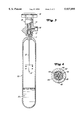
- FIG. 1 is a cross-sectional view of a cylinder and head valve assembly incorporating the apparatus of this invention.
- FIG. 2 is an enlarged view of the cylinder head assembly.
- FIG. 3 is an alternate arrangement for the interior of the cylinder.
- FIG. 4 is a section of FIG. 3 taken at lines 3--3.
- FIG. 1 the invention in one form looks from the outside like a typical dispensing unit comprising a 500 cc cylinder 10 with cylinder head valve 12 at the top end and having a valve outlet 16.
- the interior or the cylinder contains a capillary tube 13 having an inlet 14 that supplies arsine gas to a valve inlet 11.
- a liquid arsine reservoir 15 at the bottom of cylinder 10 replenishes the arsine gas it leaves the cylinder and maintains the vapor pressure of the cylinder.
- a regulator 17, located in valve 12 contains a bellows assembly 28 that automatically controls the discharge of arsine gas from the cylinder.
- a handle 18 allows manual control of a main valve element 19.
- FIG. 2 shows regulator 17 and the internals of head valve 12 in more detail. Following then the path of the arsine gas out of head valve 12, the gas first enters valve inlet 11 through capillary size flow area of tube 13.
- the body of head valve 12 contains the regulator 17. Entering gas first contacts a valve element in the form of poppet 20.
- a spring 21 biases poppet valve 20 against a valve seat 22 to create a closed condition along the gas flow path.
- the top of poppet valve 20 may retain a resilient washer or other sealing element to maintain a positive seal across valve seal 22.
- Spring 21 normally presses poppet valve 20 against valve seat 22 until the diaphragm element of the regulator, in the form of a bellows 23, expands to displace a contact plate 24.
- Contact plate 24 acts on a control pin 25 that pushes poppet 20 away from valve seat 22.
- Arsine gas may then flow through pin passage 26 around pin 25 and into a bellows chambers 27 that houses the bellows assembly 28.
- Bellows assembly 28 consists of a bellows guide 29 that defines an internal pressure chamber 30 having walls 31 that support the inside of bellows 23; an outer sleeve 32 that surrounds the exterior of bellows 23; and a bottom guide plate 33. Sealing contact at the upper end of the bellows 23 with bellows guide 29, and at the lower end of the bellows with contact plate 24, isolate the bellow from pressure within chamber 27 and the gas flow path in general. Internal chamber 30 is typically sealed at atmospheric pressure such that a reduction in pressure within bellows chamber 27 causes the gases in bellows chamber 30 to expand bellows 23 and urge contact plate 24 downward against pin 25.
- Bellows guide 29 retains sleeve 32 about its outer edge. Sleeve 32 positions with guide plate 33. Together, bellows guide 29, sleeve 32 and guide plate 29 protectively enclose bellows 23. Pin 25 passes through a central hole in the guide plate 23 to maintain its alignment with contact plate 24.
- Threaded bushing 36 clamps a multi-layer metallic diaphragm 48 to valve body 50 thereby forming a positive seal against fluid leaking past the valve stem 38.
- Handle 18 operating in conjunction with threaded valve stem 38, forces piston 51 via friction pad 52 onto diaphragm 48 to move the main valve plunger 37 down against the resisting force of spring 53. Downward movement of plunger 37 forces a Teflon sealing element 54, retained by nut 55, onto valve body 50 to create a seal at surfaces 35.
- This regulator arrangement 17 can be set to reliably prevent opening of the poppet 20 until pressure within the valve body drops to a vacuum condition. This condition is usually equal to 500 torr or less. With this setting of the regulator, opening of the main valve, with or without the protective cap in place, would not dispense arsine from the cylinder. Since the typical end-user's apparatus operates at pressure less than 100 torr, dispensing arsine at a vacuum, and particularly at pressures of 500 torr of less, has several distinct advantages. For instance there is a negative pressure at all of the arsine gas connections, so leaks can only leak into the end-user apparatus where they are quickly detected by the apparatus itself. Thus, one does not have to check joint by joint to verify that there are no leaks. In addition no external pressure regulators are required for reducing the tank pressure to pressures acceptable to the mass flow controllers. More importantly an accidental opening of a pipe connection in the arsine system is orders of magnitude less hazardous than opening of the cylinder valve with the protective cap removed.
- a restricted flow passage can further increase safety in the unlikely event that regulator 17 fails to check gas flow when desired.
- some form of capillary sized flow area offers the most flexibility and reliability as the flow restrictor. Whether provided by single or multiple small diameter bores or tightly packed materials, suitable restrictors of this type will desirably limit the transport of gas phase fluids to very low rates while permitting the flow of liquids at higher rates by capillary action.
- capillary tube 13 provides the only exit from cylinder 10.
- the winding formation of capillary 13 maintains inlet 14 near the axial and radial center of cylinder 10.
- the internal diameter of the capillary will ordinarily not exceed 0.02 millimeters (0.001 inch). This diameter limits the rate that the 250 psi saturation pressure of arsine can force arsine through the tube to only 60 milligrams per minute. Typical end-users require only 3 to 10 milligrams per minute (1 to 3 sccm).
- the length as well as the diameter of the capillary may be adjusted to provide a maximum desired flow rate through the restriction.
- the capillary In the case of arsine delivery at the previously mentioned rates, the capillary is typically 15 cm long with a bore of about 12 microns in diameter. If the diameter of the capillary is reduced to 9 microns while maintaining the same approximate length, it would require four capillaries in parallel to provide about the same flow capacity. Capillaries of this size may be made from various glass materials. Proper containment can overcome any fragility of glass.
- FIG. 3 shows a tank that uses a modified form of a capillary defined by glass rods to provide a straight capillary arrangement 13' with its inlet 14' centered at the radial and axial midpoint of cylinder 10.
- a metal tube 42 typically constructed from stainless steel, protectively surrounds a glass tube 46.
- the inside of diameter tube 46 holds a hexagon arrangement of 6 solid glass rods 43 about a central glass rod 44 and wherein all of the rods have about the same diameter.
- the spaces 45 between the rods 43 and rod 44 and between the rods 43 and the inside of tube 46 provide flow areas of capillary size for metering gas through capillary arrangement 13'.
- Micronking glass tube over the glass rods 43 and 44 provides a rigid tube and rod assembly. Therefore, even if the internal rods break, retention of the pieces by glass tube 46 will maintain capillary flow through the internal diameter of glass tube 46.
- Metal tube 42 adds further rigidity and durability when optionally shrunk around glass rods 43 and 44 to provide a reinforced unit. With the optional reinforcement of metal tube 42, fracture of the glass rods or their surrounding glass tube would leave the function of the restricted flow path through capillary arrangement 13' substantially unchanged.
- a larger port dedicated exclusively to cylinder filling may reduce times for recharging cylinders when desired or necessary for filling/delivery of other gas/gas or fluid/gas systems.
- the cylinder or valve may contain a separate entry port that by-passes the capillary or other flow restriction. Flow into the by-pass port may be controlled by a pressure, electrical or magnetic, or mechanical means to mention only a few possibilities.
- a filter element that can serve as a restriction element reciprocates between different positions, one for filling the container and another for withdrawing gas from the container.
- a restrictor it may be in the form of a sealing body wherein the sealing body is adapted for displacement away from the seal surface to establish a fluid flow path from the container that inhibits fluid flow through the valve body and for displacement toward the seal surface to establish a fluid flow path from the container to the valve outlet port that passes fluid through the restrictor and restricts fluid flow from container.
- a single port may be used to move fluid in and out of the container at automatically differing rates.
- the use of a single port through the tank inlet facilitates filling of the tank with gases by permitting the port to have a large flow area through the narrow neck of most containers.
- a displaceable restrictor element may further incorporate valve sealing elements that move with the restrictor element to block any discharge of gas unless the restrictor is fully in contact with the seal surface.
Abstract
Description
Claims (18)
Priority Applications (2)
| Application Number | Priority Date | Filing Date | Title |
|---|---|---|---|
| US09/062,599 US5937895A (en) | 1998-04-17 | 1998-04-17 | Fail-safe delivery valve for pressurized tanks |
| TW088113523A TW396255B (en) | 1998-04-17 | 1999-08-07 | Fail-safe delivery valve for pressurized tanks |
Applications Claiming Priority (1)
| Application Number | Priority Date | Filing Date | Title |
|---|---|---|---|
| US09/062,599 US5937895A (en) | 1998-04-17 | 1998-04-17 | Fail-safe delivery valve for pressurized tanks |
Publications (1)
| Publication Number | Publication Date |
|---|---|
| US5937895A true US5937895A (en) | 1999-08-17 |
Family
ID=22043548
Family Applications (1)
| Application Number | Title | Priority Date | Filing Date |
|---|---|---|---|
| US09/062,599 Expired - Lifetime US5937895A (en) | 1998-04-17 | 1998-04-17 | Fail-safe delivery valve for pressurized tanks |
Country Status (2)
| Country | Link |
|---|---|
| US (1) | US5937895A (en) |
| TW (1) | TW396255B (en) |
Cited By (51)
| Publication number | Priority date | Publication date | Assignee | Title |
|---|---|---|---|---|
| US6045115A (en) * | 1998-04-17 | 2000-04-04 | Uop Llc | Fail-safe delivery arrangement for pressurized containers |
| WO2001081822A1 (en) | 2000-04-19 | 2001-11-01 | Advanced Technology Materials, Inc. | Gas storage and dispensing system comprising regulator interiorly disposed in fluid containment vessel and adjustable in situ therein |
| US6343896B1 (en) * | 2000-06-05 | 2002-02-05 | Syltone Industries, Llc | Pressure control system for pneumatic offload |
| US6360546B1 (en) | 2000-08-10 | 2002-03-26 | Advanced Technology Materials, Inc. | Fluid storage and dispensing system featuring externally adjustable regulator assembly for high flow dispensing |
| WO2002058858A1 (en) * | 2000-11-08 | 2002-08-01 | Advanced Technology Materials, Inc. | Non-plasma $m(f)i$m(g)in situ$m(f)/i$m(g) cleaning of processing chambers using static flow methods |
| US6527009B2 (en) | 1997-11-14 | 2003-03-04 | Air Products And Chemicals, Inc. | Gas control device and method of supplying gas |
| US6554251B2 (en) * | 2000-03-17 | 2003-04-29 | Kabushiki Kaisha Neriki | Diaphragm-type valve |
| US20030150497A1 (en) * | 2002-01-11 | 2003-08-14 | Guy Rousselin | Valve device for pressurised gas cylinder |
| US20030168621A1 (en) * | 2002-03-08 | 2003-09-11 | Richard Lin | Structure of a LPG tank valve |
| US20040000339A1 (en) * | 2002-07-01 | 2004-01-01 | Heiderman Douglas Charles | Multiple dispensing check valve delivery system |
| WO2004003426A1 (en) * | 2002-07-01 | 2004-01-08 | Praxair Technology, Inc. | Multiple regulator vacuum delivery valve assembly |
| US6857447B2 (en) | 2002-06-10 | 2005-02-22 | Advanced Technology Materials, Inc. | Pressure-based gas delivery system and method for reducing risks associated with storage and delivery of high pressure gases |
| US20050054988A1 (en) * | 2003-09-05 | 2005-03-10 | Codman & Shurtleff, Inc. | Implantable pump with adjustable flow rate |
| US20050161627A1 (en) * | 2004-01-28 | 2005-07-28 | Tadayoshi Kamiya | Stop valve for gas tank |
| US20050181129A1 (en) * | 2003-02-19 | 2005-08-18 | Olander W. K. | Sub-atmospheric pressure delivery of liquids, solids and low vapor pressure gases |
| US20050257836A1 (en) * | 2004-05-18 | 2005-11-24 | Robert Boyer | Gas pressure regulator |
| US20050263075A1 (en) * | 2003-07-23 | 2005-12-01 | Luping Wang | Delivery systems for efficient vaporization of precursor source material |
| US6997202B2 (en) | 2002-12-17 | 2006-02-14 | Advanced Technology Materials, Inc. | Gas storage and dispensing system for variable conductance dispensing of gas at constant flow rate |
| US20060042723A1 (en) * | 2003-09-03 | 2006-03-02 | Christian Bleys | Integrated valve assembly with means for blocking the actuator |
| US20060273275A1 (en) * | 2005-06-01 | 2006-12-07 | Rajat Agrawal | Valve device for containing and preventing backflow of fluids |
| US20060272717A1 (en) * | 2005-06-01 | 2006-12-07 | Rajat Agrawal | Valve device for containing and preventing backflow of fluids |
| US20060278278A1 (en) * | 1999-07-30 | 2006-12-14 | Packaging Technology Holding S.A., An Luxemburg Corporation | Pressure control device for a pipeline |
| US20080000532A1 (en) * | 2006-06-30 | 2008-01-03 | Matthew Lincoln Wagner | Low release rate cylinder package |
| US20080135104A1 (en) * | 2006-12-08 | 2008-06-12 | Scott Lawrence Cooper | Fail-safe vacuum actuated valve for high pressure delivery systems |
| US20090145494A1 (en) * | 2007-12-06 | 2009-06-11 | American Air Liquide, Inc. | Integrated Valve Regulator Assembly And System For The Controlled Storage And Dispensing Of A Hazardous Material |
| US20090285650A1 (en) * | 2008-05-19 | 2009-11-19 | Jtekt Corporation | Component holding device |
| WO2009155189A1 (en) * | 2008-06-20 | 2009-12-23 | Praxair Technology, Inc. | Vacuum actuated valve for high capacity storage and delivery systems |
| US20100228399A1 (en) * | 2007-12-06 | 2010-09-09 | Udischas Richard J | Pressure regulator assembly and system for the controlled storage and dispensing of a fluid |
| US20110073200A1 (en) * | 2009-09-25 | 2011-03-31 | Illinois Tool Works Inc. | Gas regulator with valve assemblies |
| EP2796590A1 (en) | 2013-04-24 | 2014-10-29 | Praxair Technology, Inc. | Methods for using isotopically enriched levels of dopant gas compositions in an ion implantation process |
| WO2014179585A1 (en) | 2013-05-02 | 2014-11-06 | Praxair Technology, Inc. | Supply source and method for enriched selenium ion implantation |
| US9109755B2 (en) | 2010-06-18 | 2015-08-18 | Entegris, Inc. | Endpoint determination for capillary-assisted flow control |
| WO2015134430A1 (en) | 2014-03-02 | 2015-09-11 | Praxair Technology, Inc. | Boron-containing dopant compositions, systems and methods of use thereof for improving ion beam current and performance during boron ion implantation |
| US9165773B2 (en) | 2013-05-28 | 2015-10-20 | Praxair Technology, Inc. | Aluminum dopant compositions, delivery package and method of use |
| US20160258537A1 (en) * | 2015-03-04 | 2016-09-08 | Douglas C. Heiderman | Modified vacuum actuated valve assembly and sealing mechanism for improved flow stability for fluids sub-atmospherically dispensed from storage and delivery systems |
| EP3188214A1 (en) | 2015-12-29 | 2017-07-05 | Praxair Technology, Inc. | Boron-containing dopant compositions, systems and methods of use thereof for improving ion beam current and performance during boron ion implantation |
| WO2017180562A1 (en) | 2016-04-11 | 2017-10-19 | Praxair Technology, Inc. | Dopant compositions for ion implantation |
| US9897257B2 (en) | 2012-09-21 | 2018-02-20 | Entegris, Inc. | Anti-spike pressure management of pressure-regulated fluid storage and delivery vessels |
| CN108916649A (en) * | 2018-07-06 | 2018-11-30 | 珠海普燃软件科技有限公司 | A kind of liquefied gas cylinder valve attachment device and cylinder for liquefied gas |
| WO2019040554A1 (en) | 2017-08-22 | 2019-02-28 | Praxair Technology, Inc. | Antimony-containing materials for ion implantation |
| US10221201B2 (en) | 2015-12-31 | 2019-03-05 | Praxair Technology, Inc. | Tin-containing dopant compositions, systems and methods for use in ION implantation systems |
| CN109704257A (en) * | 2018-12-13 | 2019-05-03 | 李保强 | A kind of pressure pot filling valve and its working method |
| WO2019169349A1 (en) * | 2018-03-01 | 2019-09-06 | Blacoh Fluid Controls, Inc. | Industrial flow and pressure stabilizer system |
| US10927970B2 (en) * | 2018-03-28 | 2021-02-23 | Temc Co., Ltd. | Cylinder comprising fluid pressure adjustment valve having improved storage capability |
| WO2021118735A1 (en) | 2019-12-12 | 2021-06-17 | Praxair Technology, Inc. | Dopant fluid storage and dispensing systems utilizing high performance, structurally modified particulate carbon adsorbents |
| US11098402B2 (en) | 2017-08-22 | 2021-08-24 | Praxair Technology, Inc. | Storage and delivery of antimony-containing materials to an ion implanter |
| WO2021232036A1 (en) | 2020-05-11 | 2021-11-18 | Praxair Technology, Inc. | Storage and delivery of antimony-containing materials to an ion implanter |
| US11346374B2 (en) | 2020-09-08 | 2022-05-31 | Blacoh Fluid Controls, Inc. | Fluid pulsation dampeners |
| US11549523B2 (en) | 2021-04-27 | 2023-01-10 | Blacoh Fluid Controls, Inc. | Automatic fluid pump inlet stabilizers and vacuum regulators |
| USD993359S1 (en) | 2018-02-05 | 2023-07-25 | Blacoh Fluid Controls, Inc. | Valve |
| US11920862B2 (en) | 2019-12-19 | 2024-03-05 | Praxair Technology, Inc. | Methods and apparatuses for using dry ice containers |
Citations (14)
| Publication number | Priority date | Publication date | Assignee | Title |
|---|---|---|---|---|
| US4128391A (en) * | 1977-02-14 | 1978-12-05 | Braunstein Lee G | Gas regulator and gas-fired torch assemblies |
| US4157072A (en) * | 1978-02-06 | 1979-06-05 | Apv Corporation | Combination pressure-vacuum relief and antipollution valve |
| US4172471A (en) * | 1977-03-18 | 1979-10-30 | Bjoerklund Curt Arnold | Valve unit |
| US4611628A (en) * | 1984-07-04 | 1986-09-16 | Dragerwerk Aktiengesellschaft | Attenuator valve for a pressure-gas conduit |
| US4723967A (en) * | 1987-04-27 | 1988-02-09 | Advanced Technology Materials, Inc. | Valve block and container for semiconductor source reagent dispensing and/or purification |
| US4738693A (en) * | 1987-04-27 | 1988-04-19 | Advanced Technology Materials, Inc. | Valve block and container for semiconductor source reagent dispensing and/or purification |
| US4744221A (en) * | 1987-06-29 | 1988-05-17 | Olin Corporation | Zeolite based arsine storage and delivery system |
| US4936877A (en) * | 1989-07-18 | 1990-06-26 | Advanced Technology Materials, Inc. | Dopant delivery system for semiconductor manufacture |
| US5033505A (en) * | 1984-11-28 | 1991-07-23 | Nupro Company | Pressure regulator and method of assembling same |
| US5156827A (en) * | 1989-03-14 | 1992-10-20 | Advanced Technology Materials, Inc. | Apparatus, process, and composition for in-situ generation of polyhydridic compounds of group iv-vi elements |
| US5232019A (en) * | 1991-01-16 | 1993-08-03 | Luxembourg Patent Company S.A. | Faucet for bottles of compressed or liquefied gas |
| US5518528A (en) * | 1994-10-13 | 1996-05-21 | Advanced Technology Materials, Inc. | Storage and delivery system for gaseous hydride, halide, and organometallic group V compounds |
| US5704967A (en) * | 1995-10-13 | 1998-01-06 | Advanced Technology Materials, Inc. | Fluid storage and delivery system comprising high work capacity physical sorbent |
| US5707424A (en) * | 1994-10-13 | 1998-01-13 | Advanced Technology Materials, Inc. | Process system with integrated gas storage and delivery unit |
-
1998
- 1998-04-17 US US09/062,599 patent/US5937895A/en not_active Expired - Lifetime
-
1999
- 1999-08-07 TW TW088113523A patent/TW396255B/en not_active IP Right Cessation
Patent Citations (15)
| Publication number | Priority date | Publication date | Assignee | Title |
|---|---|---|---|---|
| US4128391A (en) * | 1977-02-14 | 1978-12-05 | Braunstein Lee G | Gas regulator and gas-fired torch assemblies |
| US4172471A (en) * | 1977-03-18 | 1979-10-30 | Bjoerklund Curt Arnold | Valve unit |
| US4157072A (en) * | 1978-02-06 | 1979-06-05 | Apv Corporation | Combination pressure-vacuum relief and antipollution valve |
| US4611628A (en) * | 1984-07-04 | 1986-09-16 | Dragerwerk Aktiengesellschaft | Attenuator valve for a pressure-gas conduit |
| US5033505A (en) * | 1984-11-28 | 1991-07-23 | Nupro Company | Pressure regulator and method of assembling same |
| US4723967A (en) * | 1987-04-27 | 1988-02-09 | Advanced Technology Materials, Inc. | Valve block and container for semiconductor source reagent dispensing and/or purification |
| US4738693A (en) * | 1987-04-27 | 1988-04-19 | Advanced Technology Materials, Inc. | Valve block and container for semiconductor source reagent dispensing and/or purification |
| US4744221A (en) * | 1987-06-29 | 1988-05-17 | Olin Corporation | Zeolite based arsine storage and delivery system |
| US5156827A (en) * | 1989-03-14 | 1992-10-20 | Advanced Technology Materials, Inc. | Apparatus, process, and composition for in-situ generation of polyhydridic compounds of group iv-vi elements |
| US4936877A (en) * | 1989-07-18 | 1990-06-26 | Advanced Technology Materials, Inc. | Dopant delivery system for semiconductor manufacture |
| US5232019A (en) * | 1991-01-16 | 1993-08-03 | Luxembourg Patent Company S.A. | Faucet for bottles of compressed or liquefied gas |
| US5518528A (en) * | 1994-10-13 | 1996-05-21 | Advanced Technology Materials, Inc. | Storage and delivery system for gaseous hydride, halide, and organometallic group V compounds |
| US5704965A (en) * | 1994-10-13 | 1998-01-06 | Advanced Technology Materials, Inc. | Fluid storage and delivery system utilizing carbon sorbent medium |
| US5707424A (en) * | 1994-10-13 | 1998-01-13 | Advanced Technology Materials, Inc. | Process system with integrated gas storage and delivery unit |
| US5704967A (en) * | 1995-10-13 | 1998-01-06 | Advanced Technology Materials, Inc. | Fluid storage and delivery system comprising high work capacity physical sorbent |
Cited By (104)
| Publication number | Priority date | Publication date | Assignee | Title |
|---|---|---|---|---|
| US6527009B2 (en) | 1997-11-14 | 2003-03-04 | Air Products And Chemicals, Inc. | Gas control device and method of supplying gas |
| US6648021B2 (en) | 1997-11-14 | 2003-11-18 | Air Products And Chemicals, Inc. | Gas control device and method of supplying gas |
| US6045115A (en) * | 1998-04-17 | 2000-04-04 | Uop Llc | Fail-safe delivery arrangement for pressurized containers |
| US6620256B1 (en) * | 1998-04-28 | 2003-09-16 | Advanced Technology Materials, Inc. | Non-plasma in-situ cleaning of processing chambers using static flow methods |
| US6343476B1 (en) | 1998-04-28 | 2002-02-05 | Advanced Technology Materials, Inc. | Gas storage and dispensing system comprising regulator interiorly disposed in fluid containment vessel and adjustable in situ therein |
| US20060278278A1 (en) * | 1999-07-30 | 2006-12-14 | Packaging Technology Holding S.A., An Luxemburg Corporation | Pressure control device for a pipeline |
| US6554251B2 (en) * | 2000-03-17 | 2003-04-29 | Kabushiki Kaisha Neriki | Diaphragm-type valve |
| WO2001081822A1 (en) | 2000-04-19 | 2001-11-01 | Advanced Technology Materials, Inc. | Gas storage and dispensing system comprising regulator interiorly disposed in fluid containment vessel and adjustable in situ therein |
| EP1328756A4 (en) * | 2000-04-19 | 2008-09-03 | Advanced Tech Materials | Gas storage and dispensing system comprising regulator interiorly disposed in fluid containment vessel and adjustable in situ therein |
| EP1328756A1 (en) * | 2000-04-19 | 2003-07-23 | Advanced Technology Materials, Inc. | Gas storage and dispensing system comprising regulator interiorly disposed in fluid containment vessel and adjustable in situ therein |
| US6343896B1 (en) * | 2000-06-05 | 2002-02-05 | Syltone Industries, Llc | Pressure control system for pneumatic offload |
| US6474076B2 (en) | 2000-08-10 | 2002-11-05 | Advanced Technology Materials, Inc. | Fluid storage and dispensing system featuring externally adjustable regulator assembly for high flow dispensing |
| US6360546B1 (en) | 2000-08-10 | 2002-03-26 | Advanced Technology Materials, Inc. | Fluid storage and dispensing system featuring externally adjustable regulator assembly for high flow dispensing |
| WO2002058858A1 (en) * | 2000-11-08 | 2002-08-01 | Advanced Technology Materials, Inc. | Non-plasma $m(f)i$m(g)in situ$m(f)/i$m(g) cleaning of processing chambers using static flow methods |
| US6782918B2 (en) * | 2002-01-11 | 2004-08-31 | Gce Sas | Valve device for pressurized gas cylinder |
| US20030150497A1 (en) * | 2002-01-11 | 2003-08-14 | Guy Rousselin | Valve device for pressurised gas cylinder |
| US6669167B2 (en) * | 2002-03-08 | 2003-12-30 | Richard Lin | Structure of a LPG tank valve |
| US20030168621A1 (en) * | 2002-03-08 | 2003-09-11 | Richard Lin | Structure of a LPG tank valve |
| US7798168B2 (en) | 2002-06-10 | 2010-09-21 | Advanced Technology Materials, Inc. | Pressure-based gas delivery system and method for reducing risks associated with storage and delivery of high pressure gases |
| US7614421B2 (en) | 2002-06-10 | 2009-11-10 | Advanced Technology Materials, Inc. | Pressure-based gas delivery system and method for reducing risks associated with storage and delivery of high pressure gases |
| US6857447B2 (en) | 2002-06-10 | 2005-02-22 | Advanced Technology Materials, Inc. | Pressure-based gas delivery system and method for reducing risks associated with storage and delivery of high pressure gases |
| EP2428286A2 (en) | 2002-06-10 | 2012-03-14 | Advanced Technology Materials, Inc. | Pressure-based gas delivery system and method for reducing risks associated with storage and delivery of high pressure gases |
| US20060174944A1 (en) * | 2002-06-10 | 2006-08-10 | Olander W K | Pressure-based gas delivery system and method for reducing risks associated with storage and delivery of high pressure gases |
| US7328716B2 (en) | 2002-06-10 | 2008-02-12 | Advanced Technology Materials, Inc. | Pressure-based gas delivery system and method for reducing risks associated with storage and delivery of high pressure gases |
| US20100059694A1 (en) * | 2002-06-10 | 2010-03-11 | Advanced Technology Materials, Inc. | Pressure-based gas delivery system and method for reducing risks associated with storage and delivery of high pressure gases |
| US20050224116A1 (en) * | 2002-06-10 | 2005-10-13 | Olander W K | Pressure-based gas delivery system and method for reducing risks associated with storage and delivery of high pressure gases |
| EP1534991A4 (en) * | 2002-07-01 | 2008-09-03 | Praxair Technology Inc | Multiple regulator vacuum delivery valve assembly |
| KR101027243B1 (en) * | 2002-07-01 | 2011-04-06 | 프랙스에어 테크놀로지, 인코포레이티드 | An apparatus for controlling the discharge of pressurized fluids, a cylinder and a valve assembly |
| US20040000339A1 (en) * | 2002-07-01 | 2004-01-01 | Heiderman Douglas Charles | Multiple dispensing check valve delivery system |
| JP2005531732A (en) * | 2002-07-01 | 2005-10-20 | プラクスエア・テクノロジー・インコーポレイテッド | Double regulator vacuum delivery valve assembly |
| WO2004003426A1 (en) * | 2002-07-01 | 2004-01-08 | Praxair Technology, Inc. | Multiple regulator vacuum delivery valve assembly |
| EP1534991A1 (en) * | 2002-07-01 | 2005-06-01 | Praxair Technology, Inc. | Multiple regulator vacuum delivery valve assembly |
| US20080041459A1 (en) * | 2002-12-17 | 2008-02-21 | Advanced Technology Materials, Inc. | Gas storage and dispensing system for variable conductance dispensing of gas at constant flow rate |
| US6997202B2 (en) | 2002-12-17 | 2006-02-14 | Advanced Technology Materials, Inc. | Gas storage and dispensing system for variable conductance dispensing of gas at constant flow rate |
| US7284564B2 (en) | 2002-12-17 | 2007-10-23 | Advanced Technology Materials, Inc. | Gas storage and dispensing system for variable conductance dispensing of gas at constant flow rate |
| WO2004065750A2 (en) * | 2003-01-15 | 2004-08-05 | Praxair Technology, Inc. | Multiple dispensing check valve delivery system |
| WO2004065750A3 (en) * | 2003-01-15 | 2004-11-11 | Praxair Technology Inc | Multiple dispensing check valve delivery system |
| US20050181129A1 (en) * | 2003-02-19 | 2005-08-18 | Olander W. K. | Sub-atmospheric pressure delivery of liquids, solids and low vapor pressure gases |
| US7437060B2 (en) | 2003-07-23 | 2008-10-14 | Advanced Technology Materials, Inc. | Delivery systems for efficient vaporization of precursor source material |
| US20050263075A1 (en) * | 2003-07-23 | 2005-12-01 | Luping Wang | Delivery systems for efficient vaporization of precursor source material |
| US20060042723A1 (en) * | 2003-09-03 | 2006-03-02 | Christian Bleys | Integrated valve assembly with means for blocking the actuator |
| US7287548B2 (en) * | 2003-09-03 | 2007-10-30 | Taema | Integrated valve assembly with means for blocking the actuator |
| US7867203B2 (en) | 2003-09-05 | 2011-01-11 | Codman & Shurtleff, Inc. | Implantable pump with adjustable flow rate |
| US20050054988A1 (en) * | 2003-09-05 | 2005-03-10 | Codman & Shurtleff, Inc. | Implantable pump with adjustable flow rate |
| US20080154215A1 (en) * | 2003-09-05 | 2008-06-26 | Codman & Shurtleff, Inc. | Implantable pump with adjustable flow rate |
| US7367968B2 (en) | 2003-09-05 | 2008-05-06 | Codman & Shurtleff, Inc. | Implantable pump with adjustable flow rate |
| US20050161627A1 (en) * | 2004-01-28 | 2005-07-28 | Tadayoshi Kamiya | Stop valve for gas tank |
| US7134638B2 (en) | 2004-01-28 | 2006-11-14 | Toyooki Kogyo Co., Ltd. | Stop valve for gas tank |
| US20050257836A1 (en) * | 2004-05-18 | 2005-11-24 | Robert Boyer | Gas pressure regulator |
| US20060272717A1 (en) * | 2005-06-01 | 2006-12-07 | Rajat Agrawal | Valve device for containing and preventing backflow of fluids |
| US20060273275A1 (en) * | 2005-06-01 | 2006-12-07 | Rajat Agrawal | Valve device for containing and preventing backflow of fluids |
| US20080000532A1 (en) * | 2006-06-30 | 2008-01-03 | Matthew Lincoln Wagner | Low release rate cylinder package |
| US20080135104A1 (en) * | 2006-12-08 | 2008-06-12 | Scott Lawrence Cooper | Fail-safe vacuum actuated valve for high pressure delivery systems |
| WO2008073882A1 (en) * | 2006-12-08 | 2008-06-19 | Praxair Technology, Inc. | Fail-safe vacuum actuated valve for high pressure delivery systems |
| CN101225924B (en) * | 2006-12-08 | 2010-04-14 | 普莱克斯技术有限公司 | Fail-safe vacuum actuated valve for high pressure delivery systems |
| US7708028B2 (en) | 2006-12-08 | 2010-05-04 | Praxair Technology, Inc. | Fail-safe vacuum actuated valve for high pressure delivery systems |
| US20100228399A1 (en) * | 2007-12-06 | 2010-09-09 | Udischas Richard J | Pressure regulator assembly and system for the controlled storage and dispensing of a fluid |
| US8573441B2 (en) | 2007-12-06 | 2013-11-05 | American Air Liquide, Inc. | Integrated valve regulator assembly and system for the controlled storage and dispensing of a hazardous material |
| US8322569B2 (en) | 2007-12-06 | 2012-12-04 | L'air Liquide Societe Anonyme Pour L'etude Et L'exploitation Des Procedes Georges Claude | Integrated valve regulator assembly and system for the controlled storage and dispensing of a hazardous material |
| US20090145494A1 (en) * | 2007-12-06 | 2009-06-11 | American Air Liquide, Inc. | Integrated Valve Regulator Assembly And System For The Controlled Storage And Dispensing Of A Hazardous Material |
| US20090285650A1 (en) * | 2008-05-19 | 2009-11-19 | Jtekt Corporation | Component holding device |
| US8316877B2 (en) * | 2008-05-19 | 2012-11-27 | Jtekt Corporation | Component holding device |
| WO2009155189A1 (en) * | 2008-06-20 | 2009-12-23 | Praxair Technology, Inc. | Vacuum actuated valve for high capacity storage and delivery systems |
| JP2011524964A (en) * | 2008-06-20 | 2011-09-08 | プラクスエア・テクノロジー・インコーポレイテッド | Vacuum operated valves for high capacity storage and delivery systems |
| US7905247B2 (en) | 2008-06-20 | 2011-03-15 | Praxair Technology, Inc. | Vacuum actuated valve for high capacity storage and delivery systems |
| US20090314009A1 (en) * | 2008-06-20 | 2009-12-24 | Serge Campeau | Vacuum actuated valve for high capacity storage and delivery systems |
| US20110073200A1 (en) * | 2009-09-25 | 2011-03-31 | Illinois Tool Works Inc. | Gas regulator with valve assemblies |
| US9631778B2 (en) | 2010-06-18 | 2017-04-25 | Entegris, Inc. | Endpoint determination for capillary-assisted flow control |
| US9109755B2 (en) | 2010-06-18 | 2015-08-18 | Entegris, Inc. | Endpoint determination for capillary-assisted flow control |
| US9897257B2 (en) | 2012-09-21 | 2018-02-20 | Entegris, Inc. | Anti-spike pressure management of pressure-regulated fluid storage and delivery vessels |
| US8883620B1 (en) | 2013-04-24 | 2014-11-11 | Praxair Technology, Inc. | Methods for using isotopically enriched levels of dopant gas compositions in an ion implantation process |
| EP2796590A1 (en) | 2013-04-24 | 2014-10-29 | Praxair Technology, Inc. | Methods for using isotopically enriched levels of dopant gas compositions in an ion implantation process |
| US9257286B2 (en) | 2013-05-02 | 2016-02-09 | Praxair Technology, Inc. | Supply source and method for enriched selenium ion implantation |
| WO2014179585A1 (en) | 2013-05-02 | 2014-11-06 | Praxair Technology, Inc. | Supply source and method for enriched selenium ion implantation |
| US9165773B2 (en) | 2013-05-28 | 2015-10-20 | Praxair Technology, Inc. | Aluminum dopant compositions, delivery package and method of use |
| WO2015134430A1 (en) | 2014-03-02 | 2015-09-11 | Praxair Technology, Inc. | Boron-containing dopant compositions, systems and methods of use thereof for improving ion beam current and performance during boron ion implantation |
| US9548181B2 (en) | 2014-03-03 | 2017-01-17 | Praxair Technology, Inc. | Boron-containing dopant compositions, systems and methods of use thereof for improving ion beam current and performance during boron ion implantation |
| US9570271B2 (en) | 2014-03-03 | 2017-02-14 | Praxair Technology, Inc. | Boron-containing dopant compositions, systems and methods of use thereof for improving ion beam current and performance during boron ion implantation |
| US10090133B2 (en) | 2014-03-03 | 2018-10-02 | Praxair Technology, Inc. | Boron-containing dopant compositions, systems and methods of use thereof for improving ion beam current and performance during boron ion implantation |
| US20160258537A1 (en) * | 2015-03-04 | 2016-09-08 | Douglas C. Heiderman | Modified vacuum actuated valve assembly and sealing mechanism for improved flow stability for fluids sub-atmospherically dispensed from storage and delivery systems |
| US9909670B2 (en) * | 2015-03-04 | 2018-03-06 | Praxair Technology, Inc. | Modified vacuum actuated valve assembly and sealing mechanism for improved flow stability for fluids sub-atmospherically dispensed from storage and delivery systems |
| EP3188214A1 (en) | 2015-12-29 | 2017-07-05 | Praxair Technology, Inc. | Boron-containing dopant compositions, systems and methods of use thereof for improving ion beam current and performance during boron ion implantation |
| US10221201B2 (en) | 2015-12-31 | 2019-03-05 | Praxair Technology, Inc. | Tin-containing dopant compositions, systems and methods for use in ION implantation systems |
| US10633402B2 (en) | 2015-12-31 | 2020-04-28 | Praxair Technology, Inc. | Tin-containing dopant compositions, systems and methods for use in ion implantation systems |
| WO2017180562A1 (en) | 2016-04-11 | 2017-10-19 | Praxair Technology, Inc. | Dopant compositions for ion implantation |
| WO2019040554A1 (en) | 2017-08-22 | 2019-02-28 | Praxair Technology, Inc. | Antimony-containing materials for ion implantation |
| EP3960897A1 (en) | 2017-08-22 | 2022-03-02 | Praxair Technology, Inc. | Storage and delivery of antimony-containing materials to an ion implanter |
| US11098402B2 (en) | 2017-08-22 | 2021-08-24 | Praxair Technology, Inc. | Storage and delivery of antimony-containing materials to an ion implanter |
| US10597773B2 (en) | 2017-08-22 | 2020-03-24 | Praxair Technology, Inc. | Antimony-containing materials for ion implantation |
| US10711343B2 (en) | 2017-08-22 | 2020-07-14 | Praxair Technology, Inc. | Storage and delivery of antimony-containing materials to an ion implanter |
| EP3699317A1 (en) | 2017-08-22 | 2020-08-26 | Praxair Technology, Inc. | Storage and delivery of antimony-containing materials to an ion implanter |
| USD993359S1 (en) | 2018-02-05 | 2023-07-25 | Blacoh Fluid Controls, Inc. | Valve |
| US10955079B2 (en) | 2018-03-01 | 2021-03-23 | Blacoh Fluid Controls, Inc. | Industrial flow and pressure stabilizer system |
| WO2019169349A1 (en) * | 2018-03-01 | 2019-09-06 | Blacoh Fluid Controls, Inc. | Industrial flow and pressure stabilizer system |
| US10927970B2 (en) * | 2018-03-28 | 2021-02-23 | Temc Co., Ltd. | Cylinder comprising fluid pressure adjustment valve having improved storage capability |
| CN108916649A (en) * | 2018-07-06 | 2018-11-30 | 珠海普燃软件科技有限公司 | A kind of liquefied gas cylinder valve attachment device and cylinder for liquefied gas |
| CN109704257A (en) * | 2018-12-13 | 2019-05-03 | 李保强 | A kind of pressure pot filling valve and its working method |
| WO2021118735A1 (en) | 2019-12-12 | 2021-06-17 | Praxair Technology, Inc. | Dopant fluid storage and dispensing systems utilizing high performance, structurally modified particulate carbon adsorbents |
| US11577217B2 (en) | 2019-12-12 | 2023-02-14 | Praxair Technology, Inc. | Dopant fluid storage and dispensing systems utilizing high performance, structurally modified particulate carbon adsorbents |
| US11920862B2 (en) | 2019-12-19 | 2024-03-05 | Praxair Technology, Inc. | Methods and apparatuses for using dry ice containers |
| WO2021232036A1 (en) | 2020-05-11 | 2021-11-18 | Praxair Technology, Inc. | Storage and delivery of antimony-containing materials to an ion implanter |
| US11346374B2 (en) | 2020-09-08 | 2022-05-31 | Blacoh Fluid Controls, Inc. | Fluid pulsation dampeners |
| US11549523B2 (en) | 2021-04-27 | 2023-01-10 | Blacoh Fluid Controls, Inc. | Automatic fluid pump inlet stabilizers and vacuum regulators |
| US11828303B2 (en) | 2021-04-27 | 2023-11-28 | Blacoh Fluid Controls, Inc. | Automatic fluid pump inlet stabilizers and vacuum regulators |
Also Published As
| Publication number | Publication date |
|---|---|
| TW396255B (en) | 2000-07-01 |
Similar Documents
| Publication | Publication Date | Title |
|---|---|---|
| US5937895A (en) | Fail-safe delivery valve for pressurized tanks | |
| US6045115A (en) | Fail-safe delivery arrangement for pressurized containers | |
| US6007609A (en) | Pressurized container with restrictor tube having multiple capillary passages | |
| KR100879152B1 (en) | Gas storage and dispensing system comprising regulator interiorly disposed in fluid containment vessel and adjustable in situ therein | |
| KR100416424B1 (en) | Fluid storage and dispensing system | |
| US7905247B2 (en) | Vacuum actuated valve for high capacity storage and delivery systems | |
| US7370661B2 (en) | Permeable gas assembly for gas delivery | |
| EP1534991A4 (en) | Multiple regulator vacuum delivery valve assembly | |
| EP1887276B1 (en) | Fail-safe delivery valve for pressurized tanks | |
| KR101223924B1 (en) | Permeable Gas Assembly for Gas Delivery | |
| JP4608041B2 (en) | Fail-safe delivery valve for pressurized tanks | |
| WO2004053367A9 (en) | Permeable gas assembly for gas delivery | |
| CN1114777C (en) | Pailure protection discharge valve for pressure vessel | |
| KR100697160B1 (en) | Fail-safe delivery valve for pressurized tanks | |
| CN101245894B (en) | Failure protection discharge valve for pressure vessel | |
| CN114341544A (en) | Method and apparatus for dispensing gas from a storage container |
Legal Events
| Date | Code | Title | Description |
|---|---|---|---|
| AS | Assignment |
Owner name: UOP LLC, ILLINOIS Free format text: ASSIGNMENT OF ASSIGNORS INTEREST;ASSIGNORS:LE FEBRE, DAVID A.;MARTIN, THOMAS B., JR.;REEL/FRAME:009872/0358;SIGNING DATES FROM 19980410 TO 19980414 |
|
| STCF | Information on status: patent grant |
Free format text: PATENTED CASE |
|
| FEPP | Fee payment procedure |
Free format text: PAYOR NUMBER ASSIGNED (ORIGINAL EVENT CODE: ASPN); ENTITY STATUS OF PATENT OWNER: LARGE ENTITY |
|
| REMI | Maintenance fee reminder mailed | ||
| FPAY | Fee payment |
Year of fee payment: 4 |
|
| SULP | Surcharge for late payment | ||
| AS | Assignment |
Owner name: PRAXAIR TECHNOLOGY, INC., CONNECTICUT Free format text: ASSIGNMENT OF ASSIGNORS INTEREST;ASSIGNOR:UOP LLC;REEL/FRAME:014074/0322 Effective date: 20021121 |
|
| FPAY | Fee payment |
Year of fee payment: 8 |
|
| FPAY | Fee payment |
Year of fee payment: 12 |