US5951132A - Multi-use snap-part body for slider - Google Patents
Multi-use snap-part body for slider Download PDFInfo
- Publication number
- US5951132A US5951132A US08/972,595 US97259597A US5951132A US 5951132 A US5951132 A US 5951132A US 97259597 A US97259597 A US 97259597A US 5951132 A US5951132 A US 5951132A
- Authority
- US
- United States
- Prior art keywords
- rail
- roll form
- elongate
- foot portion
- web
- Prior art date
- Legal status (The legal status is an assumption and is not a legal conclusion. Google has not performed a legal analysis and makes no representation as to the accuracy of the status listed.)
- Expired - Lifetime
Links
Images


Classifications
-
- A—HUMAN NECESSITIES
- A47—FURNITURE; DOMESTIC ARTICLES OR APPLIANCES; COFFEE MILLS; SPICE MILLS; SUCTION CLEANERS IN GENERAL
- A47B—TABLES; DESKS; OFFICE FURNITURE; CABINETS; DRAWERS; GENERAL DETAILS OF FURNITURE
- A47B88/00—Drawers for tables, cabinets or like furniture; Guides for drawers
- A47B88/40—Sliding drawers; Slides or guides therefor
- A47B88/49—Sliding drawers; Slides or guides therefor with double extensible guides or parts
- A47B88/493—Sliding drawers; Slides or guides therefor with double extensible guides or parts with rollers, ball bearings, wheels, or the like
-
- A—HUMAN NECESSITIES
- A47—FURNITURE; DOMESTIC ARTICLES OR APPLIANCES; COFFEE MILLS; SPICE MILLS; SUCTION CLEANERS IN GENERAL
- A47B—TABLES; DESKS; OFFICE FURNITURE; CABINETS; DRAWERS; GENERAL DETAILS OF FURNITURE
- A47B2210/00—General construction of drawers, guides and guide devices
- A47B2210/0002—Guide construction for drawers
- A47B2210/0029—Guide bearing means
- A47B2210/0032—Balls
-
- A—HUMAN NECESSITIES
- A47—FURNITURE; DOMESTIC ARTICLES OR APPLIANCES; COFFEE MILLS; SPICE MILLS; SUCTION CLEANERS IN GENERAL
- A47B—TABLES; DESKS; OFFICE FURNITURE; CABINETS; DRAWERS; GENERAL DETAILS OF FURNITURE
- A47B2210/00—General construction of drawers, guides and guide devices
- A47B2210/0002—Guide construction for drawers
- A47B2210/0051—Guide position
- A47B2210/0059—Guide located at the side of the drawer
-
- A—HUMAN NECESSITIES
- A47—FURNITURE; DOMESTIC ARTICLES OR APPLIANCES; COFFEE MILLS; SPICE MILLS; SUCTION CLEANERS IN GENERAL
- A47B—TABLES; DESKS; OFFICE FURNITURE; CABINETS; DRAWERS; GENERAL DETAILS OF FURNITURE
- A47B2210/00—General construction of drawers, guides and guide devices
- A47B2210/0002—Guide construction for drawers
- A47B2210/0064—Guide sequencing or synchronisation
- A47B2210/0081—Telescopic drawer rails with stop blocks, e.g. synchronization buffers
Definitions
- the present invention relates to slide assemblies. More particularly, the present invention relates to slide assemblies for slidably mounting an object within a receptacle.
- Slide assemblies are mechanisms that are used to slidably mount objects, such as drawers, within a receptacle.
- a typical slide assembly comprises two or more rails that are coupled to each other such that the rails slidably move relative to one another along the longitudinal axes of the rails.
- the rails of the slide assembly are slidably movable between an open and a closed position. In the closed or non-extended position, an inner rail is fully nested within an outer rail of the rail assembly. In the open or extended position, the majority of the inner rail extends beyond the end of the outer rail so that only a portion of the inner rail is nested within the outer rail.
- Slide assemblies are often used in environments that entail certain performance requirements regarding the moveability of one rail relative to another. For example, certain uses may require that the slide assemblies can be locked in either the open or the closed position. When locked in a given position, the slide assembly may only be closed or opened upon actuation of a control mechanism attached to the assembly. Alternatively, some uses may require that the slide assemblies can be moved out of the opened or closed position only if a certain threshold level of force is applied to the rails.
- a control piece or mechanism is mounted to one or more of the rails in the slide assembly to regulate the movement of the rails relative to each other, such as described above.
- the type of control piece mounted to the rail assembly may be varied depending on the desired control characteristics of the rail assembly.
- the control piece is usually fixedly mounted to one of the rails in the slide assembly using attachment devices such as rivets, tabs, nails, screws, etc.
- the control piece may also be mounted through spot welding.
- several drawbacks are associated with fixedly mounting a control piece to the rail.
- control piece For example, the use of special tools is required to mount the control piece with rivets or welding. This increases the expense of mounting the control piece to the rails, and also increases the amount of time required for installation. Moreover, the control piece may not be installed if such tools are not readily available.
- Another drawback relates to the control piece being installed in the wrong position or orientation relative the rails of the slide assembly. It is difficult to remove an incorrectly-mounted control piece from the rails if the control piece is fixedly mounted using rivets or welding. As a result, if the control piece is incorrectly mounted, the slide assembly may be unusable. Even if the control piece is successfully removed, the rail is often left with unsightly holes or weld spots where the control piece was previously mounted.
- control piece that may easily attached to and removed from a slide assembly.
- the control piece will not require the use of special tools or attachment devices and methods, such as screws, rivets or welding. Additionally, the control piece should be easily manufactured.
- the assembly includes an elongate first rail, an elongate second rail.
- the first rail includes a first elongate web, between a first elongate outer roll form on one side and a second elongate outer roll form on an opposing side.
- the elongate second rail includes a second elongate web and is positioned between a first elongate inner roll form on one side and a second elongate inner roll form on a opposing side.
- the first inner roll form defines a first surface overhanging the second web and the second inner roll form defines a second surface overhanging the second web which defines a first opening.
- the first plurality of ball bearings is nested between the first outer roll form and the first inner roll form Additionally, the second plurality of ball bearings is nested between the second outer roll form and the second inner roll form.
- the rail control comprises a body defining a mating surface and an alignment member raised with respect to the mating surface, the alignment member being sized and shaped to be received by the first opening of the second rail.
- the control further comprises a first foot portion along one side and a second foot portion along an opposing side. The first foot portion is sized and shaped to be secured between the second web and the first overhanging surface. The second foot portion is sized and shaped to be secured between the second web and the second overhanging surface.
- Another aspect of the invention relates to a method of controlling movement of a slide assembly including a first rail section having a first roll form and a second roll form, a second rail section having a first roll form and a second roll form and a controller having a first foot portion and a second foot portion.
- the method comprises inserting the first foot portion between a web portion and a first overhanging portion of the first rail, aligning the first alignment member with the opening, and forcing the second foot portion between the first roll form and the second roll form until the second foot portion is positioned between the web portion and a second overhanging portion of the first rail.
- Yet another aspect of the invention relates to a method of manufacturing a series of controllers for a slide assembly.
- the method comprises providing a base mold having a relief for molding a body defining a first end, a second end, a first side, a second side, a mating surface, an alignment member extending outward from the mating surface, a first interlock member along an outer portion of the first beam member and a second interlock member along an outer portion of the first beam member.
- the method further comprises selecting a first attachment mold insert from the group of lock, detent, and blank molds, inserting the first attachment mold insert at a first end of the relief, selecting a second attachment mold insert from the group of lock, detent, and blank molds, inserting the second attachment mold insert at a second end of the relief, and molding a controller.
- an improved rail controller comprising a body defining a first end, a second end, a first side, a second side, a mating surface, and an alignment member extending outward from the mating surface.
- the body defines a first elongate aperture and a first beam member along the first side of the body outboard from the first elongate aperture.
- the first aperture is sized and shaped to permit the first beam member to flex inward.
- a first interlock member is positioned along an outer portion of the first beam member.
- the body further defines a second elongate aperture and a second beam member along the second side of the body outboard from the second elongate aperture.
- the second aperture is sized and shaped to permit the second beam member to flex inward.
- a second interlock member is positioned along an outer portion of the first beam member.
- FIG. 1 is a perspective view of a drawer utilizing a pair of rail assemblies of the present invention
- FIG. 2 is a perspective view of a rail assembly utilizing a rail controller of the present invention
- FIG. 3 is a top view of the rail controller of FIG. 2;
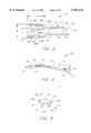
- FIG. 4 is a side view of the rail controller of FIG. 2;
- FIG. 5 is a front view of the rail controller of FIG. 2;
- FIG. 6 is a cross-sectional view of the rail assembly of FIG. 2 taken along the line 6--6;
- FIGS. 7A-7E schematically illustrate the process of mounting the rail controller FIG. 2 to an inner rail of the rail assembly
- FIG. 8 is a second perspective view of the rail assembly of FIG. 2;
- FIG. 9 is a perspective view of another embodiment of the rail assembly in an "open" position
- FIG. 9A is a cross-sectional view of the rail assembly of FIG. 9 taken along the line 9a-9a of FIG. 10;
- FIG. 11 is a perspective view of yet another embodiment of the rail assembly in an "open" position
- FIG. 12 is a perspective view of the rail assembly of FIG. 11 in a "closed" position
- FIG. 13 is a perspective view of a modular mold assembly used to manufacture the rail controller
- FIG. 14 is a top view of a lower portion of a base mold used with the mold assembly of FIG. 13;
- FIG. 15 is a side view of upper and lower portions of the base mold
- FIG. 16 is a side view of upper and lower portions of an add-on mold used with the mold assembly of FIG. 13;
- FIG. 17 is a top view of a cavity defined by the add-on mold of FIG. 16;
- FIG. 19 is a top view of a cavity defined by the add-on mold of FIG. 18;
- FIG. 20 is a side view of upper and lower portions of another embodiment of an add-on mold used with the mold assembly of FIG. 13;
- FIG. 21 is a top view of a cavity defined by the add-on mold of FIG. 20;
- FIG. 22 is a side view of upper and lower portions of another embodiment of an add-on mold used with the mold assembly of FIG. 13;
- FIG. 23 is a top view of a cavity defined by the add-on mold of FIG. 22.
- the inner rails 20 of the slide assemblies 19 are fixedly mounted to the outboard sides of the drawer side walls 14 and 15 in a well known manner.
- the corresponding outer rails 26 are fixedly mounted to inboard surfaces of the receptacle 17.
- the drawer 10 slides out of the receptacle 17 by sliding the inner rails 20 longitudinally relative to the outer rails 26.
- FIG. 2 is a perspective view of a first embodiment of the slide assembly 19.
- the slide assembly 19 is shown in an "open" position wherein the inner rail 20 is longitudinally extended relative to the outer rail 26. In the open position, only a portion of the inner rail 20 is nested within the outer rail 26 so that the proximal end 22 of the inner rail 20 is spaced from the proximal end 28 of the outer rail 26.
- FIG. 2 is a cross-sectional view of the slide assembly 19 along the line 6--6 of FIG. 2.
- FIG. 6 is a cross-sectional view of the slide assembly 19 along the line 6--6 of FIG. 2.
- the inner rail 20 and outer rail 26 are mated together in an interlocking fashion with a portion of the inner rail 20 nested within the outer rail 26, as described in detail below.
- the inner rail 20 is elongated and includes a substantially flat and thin midportion or first elongate web 40 that extends along the entire length of the inner rail 20.
- a pair of curved outer roll forms 42 extend from the side edges of the first elongate web 90 along the entire length of the inner rail 20.
- the outer roll forms 42 comprise a pair of curved walls defining opposed convex surfaces 43 and concave surfaces 44 opposite the convex surfaces 43.
- the convex surfaces 43 define a space therebetween with the space having a minimum size at the apex of the convex surfaces.
- a rectangular alignment opening 46 extends through the first elongate web 40 of the inner rail 20. The alignment opening 46 is preferably aligned with the longitudinal center-line of the elongate web 40.
- the outer rail 26 is sized and shaped to slidably mate with the inner rail 20.
- the outer rail 26 includes a substantially flat and thin midportion or second elongate web 56 that extends parallel to the first elongate web 40 of the inner rail 20.
- a pair of outer roll forms 58 extend from the edges of the second elongate web 56 along the entire length of outer rail 26.
- the outer roll forms 58 each comprise a bent wall including first wall portion 60 that extends from the elongate web 56 at an angle.
- the outer roll forms 58 then bend to form a second wall portion 62 that overhangs the second elongate web 56.
- the second wall portions 62 extend toward the concave surfaces 44 of the inner roll forms 42 of the inner rail 20.
- the second wall portions 62 of the outer roll forms 58 define a space therebetween in which the concave surfaces 44 of the inner roll forms 42 are slidably mounted.
- a plurality of ball bearings 47 are positioned between the inner roll forms 42 and outer roll forms 58.
- the slide assembly 19 further comprises a rail controller 70 that is removably mounted to the inner rail 20 in a press-fit or snap-fit fashion, as described in more detail below.
- the rail controller 70 includes a substantially thin flat main body 72 that is sized to fit snugly between the walls of the inner roll forms 42 of the inner rail 20.
- the main body 72 desirably has a small enough thickness such that the main body 72 fits between the inner roll form 40 and outer roll form 56 without interfering with the slidability of the inner rail 20 relative to the outer rail 26.
- a clearance is provided between a flat slide surface 79 of the main body and a flat inboard surface 64 of the outer elongate web 56.
- the main body 72 has a flat mating surface 78 that is positioned flush against the outboard surface 45 of the first elongate web 40 of the inner rail 20.
- An alignment member 84 comprising a raised projection extends from the mating surface 78 of the main body and is positioned within the alignment opening 46 in the inner rail 20, as described more fully below.
- FIGS. 3, 4, and 5 are top, side and front views, respectively, of the rail controller 70.
- the main body 72 of the rail controller 70 is thin and defines the flat controller mating surface 78 on one side and the flat slide surface 79 on the opposite side.
- the main body 72 has a substantially rectangular-top profile and defines a pair of opposed, curved side edges 73a, 73b, a straight proximal edge 75, and an opposed straight distal edge 77.
- the main body 72 has a width W, defined as the distance between the side edges 73a, 73b, and also has a length L, defined as the distance between the proximal edge 75 and the distal edge 77.
- the elongated apertures 80 each define a pair of elongated beam members 82 on either side thereof.
- the beam members 82 comprise the portions of the main body 72 located between the side edges 73a, 73b and the respective elongated apertures 80 so that the beam members 82 extend lengthwise along the side edges 73a and 73b.
- the side edges 73a and 73b of the main body 72 conform to the curvature of the elongated apertures 80 such that the beam members 82 each have a substantially uniform width along their length.
- the beam members 82 are configured to flex inward toward the elongated apertures 80 so as to reduce the width W of the main body 72.
- the beam width may be varied to modify the amount of force necessary to flex the beam members 82 and to control the amount of force that the beam members 82 apply to the roll forms 62 when mounted to the inner rail 20.
- an alignment member 84 is located on the mating surface 78 of the main body 72.
- the alignment member 84 comprises a rectangular-shaped raised protrusion that extends upward from the mating surface 78 of the main body 72, as best shown in FIGS. 4 and 5.
- the sides of the alignment member 84 are preferably sloped, as shown in FIG. 5, to facilitate insertion of the alignment member into the alignment opening 46 in the first elongate web 40.
- the shape of the alignment member 84 substantially conforms to the shape of the alignment opening 46 (FIGS. 2 and 6). That is, the alignment member 84 is sized and shaped to be received by the alignment opening 46.
- the rail controller 70 further includes a pair of wedge structures or interlock members 86a, 86b having a generally triangular cross-section that extend along the side edges 73a, 73b of the main body.
- the interlock members 86 extend outward in opposite directions from the upper portion of the side edges 73a, 73b of the main body 72. As shown, the height of the interlock members 86 is small relative to the height of the main body 72.
- the rail controller 70 includes a first control attachment 74 that extends from the distal edge 77 of the main body 72.
- the control attachment 74 comprises a pair of legs 90 that extend lengthwise distally from the main body 72.
- Each of the legs 90 has a proximal end connected to the distal edges 77 of the main body 72 and a distal end 94.
- the thickness of the legs increases moving toward the distal ends 94, as best seen in FIG. 4.
- the legs 90 are oriented at an angle ⁇ relative to a plane defined by the main body 72.
- the legs 90 are manufactured of a material that allows the legs 90 to be bent in a non-plastic manner such that the legs 90 can be oriented substantially parallel to the main body 72. This biases the legs 90 so that they spring back to the angled position shown in FIG. 4 after being released.
- a tab 96 extends from each of the distal ends 94 of the legs 90 so as to define a downwardly-facing step 97 at the distal ends 94.
- a wall 100 (FIG. 3) extends between the legs 90 to provide structural support thereto. In the illustrated embodiment, an elongated hole 99 extends through the wall 100.
- FIGS. 7A-7E are cross-sectional schematic views of the inner rail 20 and the rail controller 70. These figures illustrate the process by which the rail controller 70 is mounted to the inner rail 20.
- the rail controller 70 is first positioned adjacent the inner rail 20 with the mating surface 78 aligned substantially parallel to the first elongate web 40 of the inner rail 20.
- the alignment opening 46 in the first elongate web 40 facilitates correct placement of the rail controller relative to the inner rail 20.
- the alignment member 84 on the rail controller 70 is desirably aligned with the alignment opening 46 in the inner rail 20 member.
- the main body 72 of the rail controller 70 must compress in width in order for the interlock member 86b to bypass the minimum space between the apex of each of the convex surface 43 of the inner roll form 42. This compression is facilitated by the elongated apertures 80, which allow the beam members 82 and the attached interlock members 86 to flex inward towards one another to reduce the width of the main body 72. Movement of the interlock member 86 into the space between the inner roll forms 42 is thus facilitated.
- the rail controller 70 is pushed into the inner rail 20 until the interlock member 86b bypasses the convex portions of the inner roll forms 42.
- the rail controller main body 72 then expands in width so that the rail interlock members 86 spring into and seat between the inner roll forms 42.
- the alignment member 84 on the rail controller 70 also seats within the alignment opening 46 that extends through the inner rail 20. In this manner, the rail controller 70 is securely mounted to the inner rail 20.
- the above-described process can be reversed to easily remove the rail controller from the inner rail 20.
- the rail controller 70 is configured to inhibit movement of the inner rail 20 relative to the outer rail 26 in a predetermined direction so as to lock the slide assembly 19 in the open position.
- the proximal end 28 of the outer rail 26 is distally positioned beyond the distal ends 94 of the rail controller legs 90 when the slide assembly 19 is in the open position.
- the legs 90 of the rail controller 70 prevent the inner rail 20 from sliding to a closed position. That is, the legs 90 prevent the inner rail from sliding in a distal direction, or in the direction of the arrow 103.
- the distal ends 94 of the legs 90 abut against the proximal of the outer rail 26 so that the legs 90 act as a stop.
- the proximal end 28 of the outer rail 26 seats within the steps 97 (FIG. 4) on the distal ends 94 of the legs 90. It will be appreciated that the legs 90 do not prevent the inner rail 20 from sliding in a proximal direction (opposite the direction of the arrow 103).
- FIG. 8 shows the slide assembly 19 in a closed position.
- the inner rail 20 is fully nested over the outer rail 26 with the proximal ends 46 and 52 of the inner and outer rails 20 and 26 substantially aligned.
- the slide assembly 19 may be moved to the closed position by releasing the rail controller 70 from engagement with the proximal end 28 of the outer rail 26. This is accomplished by pushing the legs 90 of the rail controller 70 in the inboard direction so that the legs 90 are moved from abutment with the outer rail 26.
- the inner rail 20 is free to be moved distally, or in the direction of the arrow 103.
- the rail controller 70 In the closed position, the rail controller 70 is positioned between the elongate webs of inner rail 20 and outer rail 26, such as shown in FIG. 8.
- the legs 90 on the rail controller 70 spring open to automatically engage the proximal end 28 of the outer rail 26 to automatically lock the slide assembly 19 open.
- FIG. 9 is a perspective view, looking in the outboard direction, of a second embodiment of the slide assembly, referred to as slide assembly 19a.
- slide assembly 19a is shown in an "open" position, as described above with respect to the previous embodiment.
- the slide assembly 19a comprises an inner rail 20a, an outer rail 26a, and an intermediate rail 106 slidably mounted therebetween.
- Each of the rails 20a, 26a, and 106 are slidably movable relative to each other in a well known manner, such as described above with respect to the previous embodiment.
- FIG. 9A is a cross-sectional view of the slide assembly 19a taken along the line 9A--9A of FIG. 10.
- the inner rail 20a includes a first elongate web 40 and a pair of inner roll forms 42 extending from the sides of the first elongate web.
- the inner roll forms each comprise a curved wall defining a convex surface 43 and an opposed concave surface 44.
- the inner rail 20a is slidably nested within the intermediate rail 106.
- the intermediate rail 106 comprises a midportion or elongate web 102 having a flat inboard surface 101 and an opposed flat outboard surface 104.
- a pair of intermediate roll forms 105 extend from the sides of the elongate web 102.
- the intermediate roll forms 105 each comprise a wall having a first curved portion 107 that extends from the elongate web 102.
- the first curved portion 107 forms into a straight connector portion 108 which forms into a second curved portion 109 having a curvature opposite that of the first curved portion 107.
- a gap is defined between the second curved portion 109 and the concave surface 44 of the inner roll form 42.
- a plurality of ball bearing 47 are positioned within this gap.
- the ball bearings 47 are interconnected by a race 49 that extends through the ball bearings 47 in a well known manner.
- the outer rail 26a comprises a flat second elongate web 56, as described above regarding the previous embodiment.
- a pair of outer roll forms 58a extend from the edges of the second elongate web 56.
- the outer roll forms 58a each comprise a bent wall including a straight first wall portion 60a that extends from the elongate web 56.
- the outer roll forms 58 then bend to form a second wall portion 62a that has a curvature opposite the curvature of the second curved portion 109 of the intermediate roll forms 105 so as to form a gap therebetween.
- a plurality of ball bearings 111 are positioned within this gap.
- the ball bearings are connected by a flat bridge 115 that extends along the inboard surface 64 of the outer elongate web 56.
- the intermediate rail 106 is nested between the outer roll forms 58 of the outer rail 26a.
- the outboard surface 104 of the intermediate rail elongate web 102 is positioned flushly adjacent the inboard surface 64 of the outer elongate web 26a.
- the intermediate elongate web 102 slides along the inboard surface 64 of the outer elongate web 56 with the ball bearing bridge 115 positioned between the intermediate elongate web 102 and the outer elongate web 56.
- a rail controller 70a is removably mounted to the inner rail 20a.
- the rail controller 70a is mounted between the pair of inner roll forms 42 on the inner rail 20a in the same manner described above with respect to the previous embodiment.
- the rail controller 70a includes a main body 72 that is identical to the main body 72 described above with respect to the previous embodiment. As shown, the main body 72 is sized and positioned so as not to interfere with the slidability of any of the rails relative to one another.
- a control attachment 74a extends in a proximal direction from one end of the main body 72 of the rail controller 70.
- the control attachment 74a is configured to lock the slide assembly 19a in a "closed" position, as described more fully below.
- the control attachment 74a comprises a thin and flat elongated arm 110 that extends in a proximal direction from the main body 72.
- the elongated arm 110 is oriented at an angle relative to a plane defined by the main body 72.
- a proximal end of the elongated arm 110 forms into a rectangular, planar lock member 112.
- a pair of protruding lips 113 extend along the sides of the lock member 112.
- a rectangular aperture 114 extends through the lock member 112.
- the aperture 114 is configured to mate with a locking tab 116 (FIG. 10) located on the outer rail 26 near its proximal end 28, as described in detail below.
- FIG. 10 shows the slide assembly 19a in a closed position in which the inner rail 20a and the intermediate rail 106 are nested entirely within the outer rail 26a.
- the locking tab 116 that extends from the outer rail 26a automatically engages or snaps into the aperture 114 on the locking member 112.
- the engagement between the locking tab 116 and the aperture 114 inhibits the inner rail 20a from sliding relative to the outer rail 26a.
- the slide assembly 19a is thus locked in the closed position.
- the lock member 112 may be pulled away from the outer rail 26a to remove the aperture 114 from engagement with the locking tab 116.
- the slide assembly 19a is then free to be moved to the open position.
- a rail controller 70a is removably mounted to the inner rail 20a.
- the rail controller 70a is mounted between a pair of inner roll forms 42 on the inner rail 20a in the same manner described above with respect to the previous embodiment.
- the rail controller 70a includes a main body 72 that is identical to the main body 72 described above with respect to the previous embodiment.
- a control attachment 74a extends in a proximal direction from one end of the main body 72 of the rail controller 70.
- the control attachment 74a is configured to lock the slide assembly 19a in a "closed" position, as described more fully below.
- the control attachment 74a comprises a thin and flat elongated arm 110 that extends in a proximal direction from the main body 72.
- the elongated arm 110 is oriented at an angle relative to a plane defined by the main body 72.
- a proximal end of the elongated arm 110 forms into a rectangular, planar lock member 112.
- a pair of protruding flanges 113 extend along the sides of the lock member 112.
- a rectangular aperture 114 extends through the lock member 112.
- the aperture 114 is configured to mate with a locking tab 116 (FIG. 10) located on the outer rail 26 near its proximal end 28, as described in detail below.
- FIG. 10 shows the slide assembly 19a in a closed position in which the inner rail 20a and the intermediate rail 106 are nested entirely within the outer rail 26a.
- the locking tab 116 that extends from the outer rail 26a automatically engages or snaps into the aperture 114 on the locking member 112.
- the engagement between the locking tab 116 and the aperture 114 inhibits the inner rail 20a from sliding relative to the outer rail 26a.
- the slide assembly 19a is thus locked in the closed position.
- the lock member 112 may be pulled away from the outer rail 26a to remove the aperture 114 from engagement with the locking tab 116.
- the slide assembly 19a is then free to be moved to the open position.
- FIG. 11 is a perspective view of a third embodiment of the slide assembly, referred to as slide assembly 19b.
- slide assembly 19b is shown in an "open" position, as described above with respect to the previous embodiments.
- the slide assembly 19b comprises an inner rail 20b, an outer rail 26b, and an intermediate rail 106b slidably mounted therebetween.
- Each of the rails 20b, 26b, and 106b are slidably movable relative to each other in a well known manner, such as described above with respect to the previous embodiments.
- a rail controller 70b is removably mounted to the inner rail 20b. As discussed above with respect to the previous embodiments, the rail controller 70b is mounted between a pair of inner roll forms 42 of the inner rail 20b.
- the rail controller 70b includes a main body 72 that is identical to the main body 72 described above with respect to the first embodiment.
- a first control attachment 121 extends in a proximal direction from one side of the main body 72.
- the control attachment 121 comprises a u-shaped rail that extends from the main body 72.
- the u-shaped rail defines a rectangular locking aperture 124 therein that is sized to receive a raised tab or surface 126 located on the intermediate rail 106b.
- the control attachment 121 is configured to removably lock the slide assembly 19b in the open position, as described more fully below.
- the rail controller 70b further includes a second control attachment 122 that extends distally from the side of the main body 72 opposite the location of the control attachment 121.
- the control attachment 122 comprises a pair of forked arms 123, a portion of which are shaped to define a circular opening 110 therebetween.
- the forked arms 123 widen at their tips so as to create a widened entrance into the circular opening 110.
- the circular opening 110 defined by the forked arms 123 is sized to receive a correspondingly-shaped locking pin 132 that extends from the outer rail 26 near its distal end 30.
- the control attachment 122 is configured to retain the slide assembly 19b in a closed position, as described more fully below.
- the raised surface 126 on the intermediate rail 106b seats within the control attachment 121 so as to extend through the locking aperture 124.
- the inner rail 20 is inhibited from sliding relative to the intermediate rail 106 so that the slide assembly is locked in the open position.
- a threshold amount of force may be applied to the inner rail 20 to force the raised surface 126 to pop out of the locking aperture 124 and thereby release the control attachment 121 from engagement with the intermediate rail 106.
- FIG. 12 shows the slide assembly 19b in a closed position.
- the control attachment 122 on the rail controller engages with the locking pin 132 to thereby retain the slide assembly 19b in the closed position by inhibiting the inner rail 20b from sliding relative to the outer rail 26b.
- the locking pin 132 is positioned within the circular opening 110 and compressed between the forked arms 123 of the control attachment 122.
- a threshold force may be applied to the inner rail 20 to pull the locking pin 132 from engagement with the forked arms 123 of the control attachment 122 and slide the slide assembly 19b to the open position.
- the slide control characteristics of a particular slide assembly is determined by the particular rail controller that is mounted on the slide assembly.
- the rail controller 70 is used to provide a slide assembly with locked-open capability.
- the rail controller 70a is used to provide a slide assembly with locked-close capability.
- the rail controller 70b is used to provide detents in the open and closed positions.
- the structural configuration of the rail controller main body 72 remains substantially identical.
- the main body 70 is the only portion of the rail controller that mounts onto the slide assembly.
- the rail controllers 70, 70a, and 70b may each be easily mounted and removed from the slide assembly regardless of the particular control attachment by using the snap-fit process described with reference to FIGS. 7A-7E.
- the snap-fit mounting configuration also allows the rail controllers 70-70C to be attached to the slide assembly without the use of tools.
- FIG. 13 shows a modular mold assembly 140 that may advantageously be used to manufacture any of the embodiments of the rail controller 70.
- the mold assembly 140 comprises a lower base mold 142 that defines a central mold cavity 144 having a structural configuration forming a relief of the shape of the rail controller main body 72.
- the lower base mold 142 also defines a pair of rectangular modular mold cavities 146a and 146b on either side of the central mold cavity 144.
- the modular mold cavities 146a, 146b are configured to receive any of a variety of add-on molds 150 for manufacturing the various embodiments of the rail controllers described above.
- An upper base mold 152 (FIG. 15) fits over the lower base mold to enclose the mold cavities 144, 146a, and 146b during the molding process, as described more fully below.
- FIG. 14 is a top view of the lower base mold 142 of FIG. 13.
- the central mold cavity 144 in the lower base mold 142 defines a mold shape that is configured to form the rail controller main body 72.
- the structure of the main body 72 is identical for the different embodiments of the rail controller 70.
- the central mold cavity 144 can advantageously have the same structure for manufacturing any of the embodiments of the rail controller 70.
- FIG. 15 is a side view of the lower base mold 142 and upper base mold 152.
- the lower base mold 146 and upper base mold 152 cooperate to define the main cavity 144 therebetween for molding the main body 72 of the rail controller 70.
- the lower base mold 146 and upper base mold 152 also define the modular mold cavities 146a, 146b therebetween that are sized to receive any of a wide variety of the add-on molds 150, as described below.
- the particular add-on mold 150 that is used will be dependent on the particular embodiment of rail controller that is to be manufactured. In this manner, a single base mold 142 may be used to manufacture any of the embodiments of the rail controllers 70. This simplifies the manufacturing process and also reduces the associated tooling costs.
- FIG. 16 is a side view of an add-on mold 150a for manufacturing the rail controller 74 illustrated in FIGS. 3-5.
- the add on mold 150a comprises upper and lower portions that define a control attachment mold cavity 160a therebetween having a shape corresponding to the shape of the rail controller 74.
- FIG. 17 shows a top view of the cavity 160a formed by the add-on mold 150a.
- FIG. 20 is a side view of an add-on mold 150c for manufacturing the rail controller 121 illustrated in FIGS. 11-12.
- the add on mold 150c comprises upper and lower portions that define a cavity 160c therebetween having a shape corresponding to the shape of the rail controller 121.
- FIG. 21 shows a top view of the cavity 160c formed by the add-on mold 150c.
- FIG. 22 is a side view of an add-on mold 150d for manufacturing the rail controller 122 illustrated in FIGS. 11-12. As shown, the add on mold 150d comprises upper and lower portions that define a cavity 160d therebetween having a shape corresponding to the shape of the rail controller 122. FIG. 22 shows a top view of the cavity 160d formed by the add-on mold 150d.
- the molding process comprises selecting an add-on mold 150 that corresponds to the particular embodiment of control attachment that is to be manufactured.
- the add-on mold 150a is selected when manufacturing a rail controller 70 with the control attachment 74 shown in FIGS. 3-5.
- the desired add-on mold 150 is then inserted into one of the modular mold cavities 146 in the base mold 142. If desired, a second add-on mold 150 may be inserted into the other modular mold cavity 146. If no add-on mold is to be used, a solid box-shaped blank is inserted into the mold to prevent entry of the molding material into the modular mold cavities.
- the top portion of the base mold 142 is then positioned atop the lower portion of the base mold 142 to define the central mold cavity 144 and control attachment mold cavity 160 therebetween.
- a mold substance such as an acetyl (preferably TEFLON-filled DELRIN manufactured by DuPont) having an NC100 rating or similar durable synthetic material, is then injected into the cavities and the base mold 142 is then heated and cooled. After cooling, the upper and lower portions of the base mold 142 are separated to produce the rail controller.
- the substance used to manufacture the rail controller 70 desirably provides high strength and also provides excellent wear characteristics to the rail controller 70. Additionally, the substance desirably has excellent "memory" characteristics. That is, the substance is preferably resilient so as to return to its original shape after being deformed in a non-plastic manner.
- the above-described process advantageously allows any of the embodiments of the rail controller 170 to be manufactured using a single base mold 142.
- the add-on molds 150 may be varied to change the particular control attachment that is manufactured.
- the shape of main body 72 advantageously does not change so that the rail controller 70 is easily mounted to a slide assembly regardless of the particular control attachment used.
Abstract
Description
Claims (12)
Priority Applications (2)
| Application Number | Priority Date | Filing Date | Title |
|---|---|---|---|
| US08/972,595 US5951132A (en) | 1997-11-18 | 1997-11-18 | Multi-use snap-part body for slider |
| US09/326,813 US6224178B1 (en) | 1997-11-18 | 1999-06-07 | Multi-use snap-part body for slider |
Applications Claiming Priority (1)
| Application Number | Priority Date | Filing Date | Title |
|---|---|---|---|
| US08/972,595 US5951132A (en) | 1997-11-18 | 1997-11-18 | Multi-use snap-part body for slider |
Related Child Applications (1)
| Application Number | Title | Priority Date | Filing Date |
|---|---|---|---|
| US09/326,813 Division US6224178B1 (en) | 1997-11-18 | 1999-06-07 | Multi-use snap-part body for slider |
Publications (1)
| Publication Number | Publication Date |
|---|---|
| US5951132A true US5951132A (en) | 1999-09-14 |
Family
ID=25519861
Family Applications (2)
| Application Number | Title | Priority Date | Filing Date |
|---|---|---|---|
| US08/972,595 Expired - Lifetime US5951132A (en) | 1997-11-18 | 1997-11-18 | Multi-use snap-part body for slider |
| US09/326,813 Expired - Lifetime US6224178B1 (en) | 1997-11-18 | 1999-06-07 | Multi-use snap-part body for slider |
Family Applications After (1)
| Application Number | Title | Priority Date | Filing Date |
|---|---|---|---|
| US09/326,813 Expired - Lifetime US6224178B1 (en) | 1997-11-18 | 1999-06-07 | Multi-use snap-part body for slider |
Country Status (1)
| Country | Link |
|---|---|
| US (2) | US5951132A (en) |
Cited By (32)
| Publication number | Priority date | Publication date | Assignee | Title |
|---|---|---|---|---|
| US6126255A (en) * | 2000-03-03 | 2000-10-03 | Yang; Jun-Long | Retaining device for a detachable drawer track |
| US6145945A (en) * | 1998-11-12 | 2000-11-14 | Accuride International, Inc. | Drawer slide bearing retainer and guide block |
| US6450600B1 (en) * | 2001-08-03 | 2002-09-17 | King Slide Works Co., Ltd. | Retaining structure for a track device for preventing inadvertent inward movement |
| US20030042831A1 (en) * | 2001-08-17 | 2003-03-06 | Baoloc Le | Jacket for use with a lock latch, a lock latch incorporating the same and a slide incorporating the lock latch and jacket |
| US6643091B2 (en) | 2001-03-05 | 2003-11-04 | Hewlett-Packard Development Company | Automated data cartridge import/export drawer |
| US6648428B2 (en) | 2001-04-18 | 2003-11-18 | Hewlett-Packard Development Company, L.P. | Reconfigurable data cartridge import/export drawer |
| US6685288B1 (en) * | 2000-10-16 | 2004-02-03 | Compx International Inc. | Drawer slide with sequence control mechanism |
| US20040055984A1 (en) * | 2002-09-23 | 2004-03-25 | Gundlach John Geoffrey | Adjustable apparatus to support an electronic device within a rack |
| US6813113B1 (en) * | 1999-02-25 | 2004-11-02 | Hewlett-Packard Development Company, L.P. | Data cartridge import/export drawer having three-element, two-configuration slide |
| US20050116594A1 (en) * | 2002-09-25 | 2005-06-02 | Barry Alfred E.Jr. | Slide rail having front release latch |
| US6979067B2 (en) | 2003-05-30 | 2005-12-27 | Central Industrial Supply Company | Cam lock with torsion spring for a drawer slide |
| US20060066190A1 (en) * | 2004-09-29 | 2006-03-30 | Mike Edward Hay | Friction slide |
| US20060119238A1 (en) * | 2002-11-13 | 2006-06-08 | Thomas Sagel | Mounting for an extension piece of a tall cabinet |
| US20080012456A1 (en) * | 2006-06-06 | 2008-01-17 | Judge Ronald J | Server cabinet with slide assembly |
| US20080083515A1 (en) * | 2006-09-18 | 2008-04-10 | Arrow Tru-Line, Inc. | Overhead door track system |
| US20080100083A1 (en) * | 2006-10-31 | 2008-05-01 | Barclay De Tolly Paul E | Floating liner mount attachment and method |
| US20080279490A1 (en) * | 2007-05-08 | 2008-11-13 | Waterloo Industries, Inc. | Sliding friction reducer |
| US20080278043A1 (en) * | 2007-05-08 | 2008-11-13 | Waterloo Industries, Inc. | Drawer lock mechanism |
| US20090134757A1 (en) * | 2007-11-28 | 2009-05-28 | Schweers Dennis John | Frictional drawer slide dampener |
| US20090250421A1 (en) * | 2008-04-03 | 2009-10-08 | Wang Chun-Ping | Fixing seat for rail of modem/servo carrying and stowing rack |
| US20100046161A1 (en) * | 2008-08-25 | 2010-02-25 | Chi-Tsun Cheng | Rail assembly for an industrial computer |
| US20110220627A1 (en) * | 2010-03-15 | 2011-09-15 | Lincoln Global, Inc. | Slideable welding power source housing assembly |
| US20120051675A1 (en) * | 2010-08-28 | 2012-03-01 | Nan Juen International Co., Ltd. | Sliding rail receiving positioning structure |
| US8317278B2 (en) | 2010-08-18 | 2012-11-27 | Knape & Vogt Manufacturing Company | Releasably locking slide assemblies |
| US8534719B2 (en) | 2011-09-09 | 2013-09-17 | Adams Rite Manufacturing Co. | Door top latching actuation |
| US20140152165A1 (en) * | 2011-06-17 | 2014-06-05 | Schock Metallwerk Gmbh | Drawer guide |
| DE102013217712A1 (en) * | 2013-09-05 | 2015-03-05 | Schock Metallwerk Gmbh | pull-out guide |
| US9107500B2 (en) | 2011-08-09 | 2015-08-18 | Schock Metallwerk Gmbh | Extraction guide |
| US20180172071A1 (en) * | 2015-07-03 | 2018-06-21 | Thk Co., Ltd. | Guide apparatus and equipment using the same |
| US11337520B2 (en) * | 2017-12-21 | 2022-05-24 | Segos | Sliding device for drawer |
| US11464333B2 (en) * | 2018-02-01 | 2022-10-11 | Julius Blum Gmbh | Loading rail for a pull-out guide for a drawer |
| USD973038S1 (en) * | 2020-01-14 | 2022-12-20 | Athena Data Technology Ltd. | Gate antenna |
Families Citing this family (7)
| Publication number | Priority date | Publication date | Assignee | Title |
|---|---|---|---|---|
| WO2002067724A1 (en) | 2001-02-28 | 2002-09-06 | Accuride International Inc. | Snap-in latch |
| WO2003049572A2 (en) * | 2001-12-12 | 2003-06-19 | Pentair Electronic Packaging Co. | Improved slide rail assembly |
| DE10241683A1 (en) * | 2002-09-09 | 2004-03-18 | BSH Bosch und Siemens Hausgeräte GmbH | Rail drawer for horizontal or vertical extension of pull-out element has additional outer rail connected to outer rail and reinforcing it, or additional rail connected to slide rail and reinforcing it |
| US7918430B2 (en) | 2008-06-23 | 2011-04-05 | Extreme Broadband Engineering, Llc | Methods and apparatus for mounting devices |
| CN101719005B (en) * | 2008-10-09 | 2012-05-16 | 英业达股份有限公司 | Slide rail structure |
| US9237806B2 (en) * | 2012-04-17 | 2016-01-19 | Aten International Co., Ltd. | Sliding track assembly |
| US10485132B2 (en) * | 2016-05-27 | 2019-11-19 | Hewlett Packard Enterprise Development Lp | Rail kits |
Citations (23)
| Publication number | Priority date | Publication date | Assignee | Title |
|---|---|---|---|---|
| US2528910A (en) * | 1948-02-27 | 1950-11-07 | Browne Morse Company | Snap-on drawer lock |
| US3923347A (en) * | 1972-10-12 | 1975-12-02 | Wright Barry Corp | Suspension latch |
| US4370007A (en) * | 1979-02-08 | 1983-01-25 | Jacmorr Manufacturing Limited | Sliding drawer suspension |
| US4469384A (en) * | 1979-11-07 | 1984-09-04 | Jacmorr Manufacturing Limited | Three part slide |
| US4573731A (en) * | 1982-10-28 | 1986-03-04 | Knaack Manufacturing Company | Vehicle storage drawer unit |
| DE3518359A1 (en) * | 1985-05-22 | 1986-11-27 | Paul Hettich GmbH & Co, 4983 Kirchlengern | Method and device for mounting a pull-out guide, consisting of two pairs of rails, for a drawer |
| US4747242A (en) * | 1985-07-01 | 1988-05-31 | Up And Down Garage System A/S | Two level structure for parking vehicles or storing goods |
| US4749242A (en) * | 1987-06-22 | 1988-06-07 | Robert Rechberg | Drawer slide |
| US4872734A (en) * | 1987-06-22 | 1989-10-10 | Robert Rechberg | Drawer slides with self-actuating latching systems |
| US4998828A (en) * | 1989-10-02 | 1991-03-12 | General Devices Co., Inc. | Over and under telescoping slide assembly |
| US5085523A (en) * | 1989-08-07 | 1992-02-04 | General Devices Co., Inc. | Slide release mechanism |
| US5169238A (en) * | 1991-06-10 | 1992-12-08 | Waterloo Furniture Components Limited | Take apart lock |
| US5181782A (en) * | 1990-09-06 | 1993-01-26 | Thomas Regout N.V. | Telescopic rail with locking mechanism |
| EP0585037A1 (en) * | 1992-08-24 | 1994-03-02 | KNAPE & VOGT MANUFACTURING COMPANY | Drawer slide assembly |
| US5388902A (en) * | 1993-02-01 | 1995-02-14 | Snap-On Incorporated | Sliding latch mechanism for a cabinet drawer |
| US5411333A (en) * | 1992-08-20 | 1995-05-02 | Knape & Vogt Manufacturing Company | Recyclable drawer slide |
| US5466060A (en) * | 1992-08-20 | 1995-11-14 | Knape & Vogt Manufacturing Company | Drawer slide with access holes |
| US5507571A (en) * | 1992-08-20 | 1996-04-16 | Knape & Vogt Manufacturing Company | Drawer slide assembly |
| US5564767A (en) * | 1994-08-23 | 1996-10-15 | Strepek; John E. | Motorized extendible drawer apparatus for a vehicle |
| US5570915A (en) * | 1993-11-30 | 1996-11-05 | Adams Rite Sabre International | Flush-mounted door latch |
| US5577821A (en) * | 1995-03-24 | 1996-11-26 | Chu; Leo | Sliding track assembly for drawers |
| US5588686A (en) * | 1994-12-05 | 1996-12-31 | Adams Rite Manufacturing Company | Temperature responsive mechanism for controllably deadlocking a door to a door frame |
| US5671988A (en) * | 1995-05-24 | 1997-09-30 | Waterloo Furniture Components, Ltd. | Drawer slide latch |
Family Cites Families (3)
| Publication number | Priority date | Publication date | Assignee | Title |
|---|---|---|---|---|
| USD291636S (en) | 1985-04-25 | 1987-09-01 | Actron Mfg., Inc. | Drawer slide |
| US4986674A (en) * | 1990-01-05 | 1991-01-22 | Irvin Automotive Products, Inc. | Vehicle accessory glide apparatus |
| USD385474S (en) | 1996-04-09 | 1997-10-28 | Actron Manufacturing, Inc. | Drawer latch |
-
1997
- 1997-11-18 US US08/972,595 patent/US5951132A/en not_active Expired - Lifetime
-
1999
- 1999-06-07 US US09/326,813 patent/US6224178B1/en not_active Expired - Lifetime
Patent Citations (23)
| Publication number | Priority date | Publication date | Assignee | Title |
|---|---|---|---|---|
| US2528910A (en) * | 1948-02-27 | 1950-11-07 | Browne Morse Company | Snap-on drawer lock |
| US3923347A (en) * | 1972-10-12 | 1975-12-02 | Wright Barry Corp | Suspension latch |
| US4370007A (en) * | 1979-02-08 | 1983-01-25 | Jacmorr Manufacturing Limited | Sliding drawer suspension |
| US4469384A (en) * | 1979-11-07 | 1984-09-04 | Jacmorr Manufacturing Limited | Three part slide |
| US4573731A (en) * | 1982-10-28 | 1986-03-04 | Knaack Manufacturing Company | Vehicle storage drawer unit |
| DE3518359A1 (en) * | 1985-05-22 | 1986-11-27 | Paul Hettich GmbH & Co, 4983 Kirchlengern | Method and device for mounting a pull-out guide, consisting of two pairs of rails, for a drawer |
| US4747242A (en) * | 1985-07-01 | 1988-05-31 | Up And Down Garage System A/S | Two level structure for parking vehicles or storing goods |
| US4749242A (en) * | 1987-06-22 | 1988-06-07 | Robert Rechberg | Drawer slide |
| US4872734A (en) * | 1987-06-22 | 1989-10-10 | Robert Rechberg | Drawer slides with self-actuating latching systems |
| US5085523A (en) * | 1989-08-07 | 1992-02-04 | General Devices Co., Inc. | Slide release mechanism |
| US4998828A (en) * | 1989-10-02 | 1991-03-12 | General Devices Co., Inc. | Over and under telescoping slide assembly |
| US5181782A (en) * | 1990-09-06 | 1993-01-26 | Thomas Regout N.V. | Telescopic rail with locking mechanism |
| US5169238A (en) * | 1991-06-10 | 1992-12-08 | Waterloo Furniture Components Limited | Take apart lock |
| US5466060A (en) * | 1992-08-20 | 1995-11-14 | Knape & Vogt Manufacturing Company | Drawer slide with access holes |
| US5507571A (en) * | 1992-08-20 | 1996-04-16 | Knape & Vogt Manufacturing Company | Drawer slide assembly |
| US5411333A (en) * | 1992-08-20 | 1995-05-02 | Knape & Vogt Manufacturing Company | Recyclable drawer slide |
| EP0585037A1 (en) * | 1992-08-24 | 1994-03-02 | KNAPE & VOGT MANUFACTURING COMPANY | Drawer slide assembly |
| US5388902A (en) * | 1993-02-01 | 1995-02-14 | Snap-On Incorporated | Sliding latch mechanism for a cabinet drawer |
| US5570915A (en) * | 1993-11-30 | 1996-11-05 | Adams Rite Sabre International | Flush-mounted door latch |
| US5564767A (en) * | 1994-08-23 | 1996-10-15 | Strepek; John E. | Motorized extendible drawer apparatus for a vehicle |
| US5588686A (en) * | 1994-12-05 | 1996-12-31 | Adams Rite Manufacturing Company | Temperature responsive mechanism for controllably deadlocking a door to a door frame |
| US5577821A (en) * | 1995-03-24 | 1996-11-26 | Chu; Leo | Sliding track assembly for drawers |
| US5671988A (en) * | 1995-05-24 | 1997-09-30 | Waterloo Furniture Components, Ltd. | Drawer slide latch |
Cited By (48)
| Publication number | Priority date | Publication date | Assignee | Title |
|---|---|---|---|---|
| US6145945A (en) * | 1998-11-12 | 2000-11-14 | Accuride International, Inc. | Drawer slide bearing retainer and guide block |
| US6254210B1 (en) * | 1998-11-12 | 2001-07-03 | Accuride International, Inc | Drawer slide bearing retainer and guide block |
| US6813113B1 (en) * | 1999-02-25 | 2004-11-02 | Hewlett-Packard Development Company, L.P. | Data cartridge import/export drawer having three-element, two-configuration slide |
| US6126255A (en) * | 2000-03-03 | 2000-10-03 | Yang; Jun-Long | Retaining device for a detachable drawer track |
| US6685288B1 (en) * | 2000-10-16 | 2004-02-03 | Compx International Inc. | Drawer slide with sequence control mechanism |
| US6643091B2 (en) | 2001-03-05 | 2003-11-04 | Hewlett-Packard Development Company | Automated data cartridge import/export drawer |
| US20060091767A1 (en) * | 2001-04-18 | 2006-05-04 | Chaloner Michael J | Reconfigurable data cartridge import/export drawer |
| US7048345B2 (en) | 2001-04-18 | 2006-05-23 | Hewlett-Packard Development Company, L.P. | Reconfigurable data cartridge import/export drawer |
| US6648428B2 (en) | 2001-04-18 | 2003-11-18 | Hewlett-Packard Development Company, L.P. | Reconfigurable data cartridge import/export drawer |
| US7104618B2 (en) | 2001-04-18 | 2006-09-12 | Hewlett-Packard Development Company, L.P. | Reconfigurable data cartridge import/export drawer |
| US6450600B1 (en) * | 2001-08-03 | 2002-09-17 | King Slide Works Co., Ltd. | Retaining structure for a track device for preventing inadvertent inward movement |
| US6764150B2 (en) * | 2001-08-17 | 2004-07-20 | Accuride International, Inc. | Jacket for use with a lock latch, a lock latch incorporating the same and a slide incorporating the lock latch and jacket |
| US20030042831A1 (en) * | 2001-08-17 | 2003-03-06 | Baoloc Le | Jacket for use with a lock latch, a lock latch incorporating the same and a slide incorporating the lock latch and jacket |
| US6935521B2 (en) * | 2002-09-23 | 2005-08-30 | International Business Machines Corporation | Adjustable apparatus to support an electronic device within a rack |
| US20040055984A1 (en) * | 2002-09-23 | 2004-03-25 | Gundlach John Geoffrey | Adjustable apparatus to support an electronic device within a rack |
| US7029080B2 (en) * | 2002-09-25 | 2006-04-18 | Central Industrial Supply Company | Slide rail having front release latch |
| US20050116594A1 (en) * | 2002-09-25 | 2005-06-02 | Barry Alfred E.Jr. | Slide rail having front release latch |
| US7971944B2 (en) * | 2002-11-13 | 2011-07-05 | Vauth-Sagel Holding Gmbh & Co. Kg | Mounting for an extension piece of a tall cabinet |
| US20060119238A1 (en) * | 2002-11-13 | 2006-06-08 | Thomas Sagel | Mounting for an extension piece of a tall cabinet |
| US6979067B2 (en) | 2003-05-30 | 2005-12-27 | Central Industrial Supply Company | Cam lock with torsion spring for a drawer slide |
| US20060066190A1 (en) * | 2004-09-29 | 2006-03-30 | Mike Edward Hay | Friction slide |
| US7347516B2 (en) * | 2004-09-29 | 2008-03-25 | Waterloo Industries, Inc. | Friction slide |
| US20080012456A1 (en) * | 2006-06-06 | 2008-01-17 | Judge Ronald J | Server cabinet with slide assembly |
| US20080083515A1 (en) * | 2006-09-18 | 2008-04-10 | Arrow Tru-Line, Inc. | Overhead door track system |
| US20080100083A1 (en) * | 2006-10-31 | 2008-05-01 | Barclay De Tolly Paul E | Floating liner mount attachment and method |
| US20080279490A1 (en) * | 2007-05-08 | 2008-11-13 | Waterloo Industries, Inc. | Sliding friction reducer |
| US7946663B2 (en) | 2007-05-08 | 2011-05-24 | Waterloo Industries, Inc. | Drawer lock mechanism |
| US20080278043A1 (en) * | 2007-05-08 | 2008-11-13 | Waterloo Industries, Inc. | Drawer lock mechanism |
| US7946667B2 (en) | 2007-11-28 | 2011-05-24 | Schweers Dennis John | Frictional drawer slide dampener |
| US20090134757A1 (en) * | 2007-11-28 | 2009-05-28 | Schweers Dennis John | Frictional drawer slide dampener |
| US20090250421A1 (en) * | 2008-04-03 | 2009-10-08 | Wang Chun-Ping | Fixing seat for rail of modem/servo carrying and stowing rack |
| US20100046161A1 (en) * | 2008-08-25 | 2010-02-25 | Chi-Tsun Cheng | Rail assembly for an industrial computer |
| US8104730B2 (en) * | 2008-08-25 | 2012-01-31 | Lif J.K. Corporation | Rail assembly for an industrial computer |
| US8253069B2 (en) * | 2010-03-15 | 2012-08-28 | Lincoln Global, Inc. | Slideable welding power source housing assembly |
| US20110220627A1 (en) * | 2010-03-15 | 2011-09-15 | Lincoln Global, Inc. | Slideable welding power source housing assembly |
| US8317278B2 (en) | 2010-08-18 | 2012-11-27 | Knape & Vogt Manufacturing Company | Releasably locking slide assemblies |
| US20120051675A1 (en) * | 2010-08-28 | 2012-03-01 | Nan Juen International Co., Ltd. | Sliding rail receiving positioning structure |
| US20140152165A1 (en) * | 2011-06-17 | 2014-06-05 | Schock Metallwerk Gmbh | Drawer guide |
| US9161626B2 (en) * | 2011-06-17 | 2015-10-20 | Schock Metallwerk Gmbh | Drawer guide |
| US9107500B2 (en) | 2011-08-09 | 2015-08-18 | Schock Metallwerk Gmbh | Extraction guide |
| US8534719B2 (en) | 2011-09-09 | 2013-09-17 | Adams Rite Manufacturing Co. | Door top latching actuation |
| DE102013217712A1 (en) * | 2013-09-05 | 2015-03-05 | Schock Metallwerk Gmbh | pull-out guide |
| DE102013217712B4 (en) | 2013-09-05 | 2023-07-27 | Schock Metallwerk Gmbh | drawer guide |
| US20180172071A1 (en) * | 2015-07-03 | 2018-06-21 | Thk Co., Ltd. | Guide apparatus and equipment using the same |
| US10428872B2 (en) * | 2015-07-03 | 2019-10-01 | Thk Co., Ltd. | Guide apparatus and equipment using the same |
| US11337520B2 (en) * | 2017-12-21 | 2022-05-24 | Segos | Sliding device for drawer |
| US11464333B2 (en) * | 2018-02-01 | 2022-10-11 | Julius Blum Gmbh | Loading rail for a pull-out guide for a drawer |
| USD973038S1 (en) * | 2020-01-14 | 2022-12-20 | Athena Data Technology Ltd. | Gate antenna |
Also Published As
| Publication number | Publication date |
|---|---|
| US6224178B1 (en) | 2001-05-01 |
Similar Documents
| Publication | Publication Date | Title |
|---|---|---|
| US5951132A (en) | Multi-use snap-part body for slider | |
| CA2345531C (en) | File interlock system and mechanism | |
| US10557491B2 (en) | Fastening device for a furniture panel | |
| US5507571A (en) | Drawer slide assembly | |
| US5316389A (en) | Drawer slide assembly | |
| US5269063A (en) | Step-slide type cutter knife with automatic lock mechanism | |
| US6677526B2 (en) | Protector for wire harness | |
| KR0137796B1 (en) | Automatic lock slider for slide fastener | |
| US8002570B2 (en) | Resin molded parts with lock arm, connector using it and method for forming resin molded parts with lock arm | |
| US20120133259A1 (en) | Drawer | |
| US20010006319A1 (en) | Drawer slide with front-mounted stop/anti-rebound mechanism | |
| US5974667A (en) | Friction slide rail assembly with overmold bearing shell | |
| EP1416829B1 (en) | LOCK LATCH INCORPORATING A JAcket AND A SLIDE INCORPORATING THE LOCK LATCH AND JACKET | |
| EP0972468B1 (en) | Drawer slide and drawer incorporating quick-release connection | |
| WO1994028773A1 (en) | Detachable chair arm | |
| JPH0845596A (en) | Connector | |
| CA2687134A1 (en) | Sliding friction reducer | |
| US8403435B2 (en) | Sliding apparatus and sliding structure | |
| US5184454A (en) | Cable carrier chain | |
| DE202015104438U1 (en) | Device for moving a movable furniture part and furniture | |
| US20040242083A1 (en) | Connector | |
| US6280086B1 (en) | Telescopic rail with stop block | |
| US20030193171A1 (en) | Binding system for and on a ski or snowboard | |
| CN102068131B (en) | Drawer assembly | |
| JP3432157B2 (en) | Metal cabinet coupling |
Legal Events
| Date | Code | Title | Description |
|---|---|---|---|
| AS | Assignment |
Owner name: JONATHAN MANUFACTURING CORPORATION, CALIFORNIA Free format text: ASSIGNMENT OF ASSIGNORS INTEREST;ASSIGNOR:CIROCCO, PAUL;REEL/FRAME:008833/0880 Effective date: 19971115 |
|
| STCF | Information on status: patent grant |
Free format text: PATENTED CASE |
|
| FEPP | Fee payment procedure |
Free format text: PAYOR NUMBER ASSIGNED (ORIGINAL EVENT CODE: ASPN); ENTITY STATUS OF PATENT OWNER: SMALL ENTITY Free format text: PAT HOLDER CLAIMS SMALL ENTITY STATUS, ENTITY STATUS SET TO SMALL (ORIGINAL EVENT CODE: LTOS); ENTITY STATUS OF PATENT OWNER: SMALL ENTITY |
|
| FPAY | Fee payment |
Year of fee payment: 4 |
|
| SULP | Surcharge for late payment | ||
| FEPP | Fee payment procedure |
Free format text: ENTITY STATUS SET TO SMALL (ORIGINAL EVENT CODE: SMAL); ENTITY STATUS OF PATENT OWNER: SMALL ENTITY |
|
| AS | Assignment |
Owner name: JONATHAN MANUFACTURING CORPORATION DOING BUSINESS Free format text: CLARIFICATION OF ASSIGNMENTS AND RECORDATION OF FICTITIOUS BUSINESS NAME;ASSIGNOR:JONATHAN MANUFACTURING CORPORATION DOING BUSINESS AS JONATHAN ENGINEERED SOLUTIONS;REEL/FRAME:015035/0529 Effective date: 20040303 |
|
| AS | Assignment |
Owner name: ANTARES CAPITAL CORPORATION, AS AGENT, ILLINOIS Free format text: SECURITY AGREEMENT;ASSIGNOR:JONATHAN MANUFACTURING CORPORATION;REEL/FRAME:015098/0225 Effective date: 20040312 |
|
| FPAY | Fee payment |
Year of fee payment: 8 |
|
| AS | Assignment |
Owner name: JONATHAN MANUFACTURING CORPORATION, CALIFORNIA Free format text: RELEASE BY SECURED PARTY;ASSIGNOR:ANARES CAPITAL CORPORATION;REEL/FRAME:019501/0585 Effective date: 20070629 |
|
| AS | Assignment |
Owner name: GENERAL ELECTRIC CAPITAL CORPORATION, AS ADMINISTR Free format text: SECURITY AGREEMENT;ASSIGNOR:JONATHAN MANUFACTURED CORPORATION;REEL/FRAME:019511/0611 Effective date: 20070629 |
|
| FPAY | Fee payment |
Year of fee payment: 12 |
|
| AS | Assignment |
Owner name: JONATHAN MANUFACTURED CORPORATION, CALIFORNIA Free format text: RELEASE OF PATENT SECURITY AGREEMENT;ASSIGNOR:GENERAL ELECTRIC CAPITAL CORPORATION, AS ADMINISTRATIVE AGENT;REEL/FRAME:026590/0803 Effective date: 20110713 Owner name: LEVINE LEICHTMAN CAPITAL PARTNERS DEEP VALUE FUND, Free format text: PATENT SECURITY AGREEMENT;ASSIGNORS:JONATHAN MANUFACTURING CORPORATION;JONATHAN ENGINEERED SOLUTIONS CORP.;JONATHAN ACQUISITION COMPANY;AND OTHERS;REEL/FRAME:026590/0812 Effective date: 20110713 |
|
| AS | Assignment |
Owner name: LEVINE LEICHTMAN CAPITAL PARTNERS DEEP VALUE FUND, Free format text: SUBORDINATED PATENT SECURITY AGREEMENT;ASSIGNORS:JONATHAN MANUFACTURING CORPORATION;JONATHAN ENGINEERED SOLUTIONS CORP.;JONATHAN ACQUISITION COMPANY;AND OTHERS;REEL/FRAME:026597/0147 Effective date: 20110713 |
|
| AS | Assignment |
Owner name: JONATHAN ACQUISITION COMPANY, CALIFORNIA Free format text: TERMINATION AND RELEASE OF GRANT OF SECURITY INTEREST IN PATENT RIGHTS (SUBORDINATED);ASSIGNOR:LEVINE LEICHTMAN CAPITAL PARTNERS DEEP VALUE FUND, L.P., AS AGENT;REEL/FRAME:040645/0366 Effective date: 20161031 Owner name: JONATHAN HOLDING COMPANY, CALIFORNIA Free format text: TERMINATION AND RELEASE OF GRANT OF SECURITY INTEREST IN PATENT RIGHTS;ASSIGNOR:LEVINE LEICHTMAN CAPITAL PARTNERS DEEP VALUE FUND, L.P., AS AGENT;REEL/FRAME:040645/0375 Effective date: 20161031 Owner name: JONATHAN ACQUISITION COMPANY, CALIFORNIA Free format text: TERMINATION AND RELEASE OF GRANT OF SECURITY INTEREST IN PATENT RIGHTS;ASSIGNOR:LEVINE LEICHTMAN CAPITAL PARTNERS DEEP VALUE FUND, L.P., AS AGENT;REEL/FRAME:040645/0375 Effective date: 20161031 Owner name: JONATHAN ENGINEERED SOLUTIONS CORP., CALIFORNIA Free format text: TERMINATION AND RELEASE OF GRANT OF SECURITY INTEREST IN PATENT RIGHTS (SUBORDINATED);ASSIGNOR:LEVINE LEICHTMAN CAPITAL PARTNERS DEEP VALUE FUND, L.P., AS AGENT;REEL/FRAME:040645/0366 Effective date: 20161031 Owner name: JONATHAN MANUFACTURING CORPORATION, CALIFORNIA Free format text: TERMINATION AND RELEASE OF GRANT OF SECURITY INTEREST IN PATENT RIGHTS;ASSIGNOR:LEVINE LEICHTMAN CAPITAL PARTNERS DEEP VALUE FUND, L.P., AS AGENT;REEL/FRAME:040645/0375 Effective date: 20161031 Owner name: JONATHAN HOLDING COMPANY, CALIFORNIA Free format text: TERMINATION AND RELEASE OF GRANT OF SECURITY INTEREST IN PATENT RIGHTS (SUBORDINATED);ASSIGNOR:LEVINE LEICHTMAN CAPITAL PARTNERS DEEP VALUE FUND, L.P., AS AGENT;REEL/FRAME:040645/0366 Effective date: 20161031 Owner name: JONATHAN MANUFACTURING CORPORATION, CALIFORNIA Free format text: TERMINATION AND RELEASE OF GRANT OF SECURITY INTEREST IN PATENT RIGHTS (SUBORDINATED);ASSIGNOR:LEVINE LEICHTMAN CAPITAL PARTNERS DEEP VALUE FUND, L.P., AS AGENT;REEL/FRAME:040645/0366 Effective date: 20161031 Owner name: JONATHAN ENGINEERED SOLUTIONS CORP., CALIFORNIA Free format text: TERMINATION AND RELEASE OF GRANT OF SECURITY INTEREST IN PATENT RIGHTS;ASSIGNOR:LEVINE LEICHTMAN CAPITAL PARTNERS DEEP VALUE FUND, L.P., AS AGENT;REEL/FRAME:040645/0375 Effective date: 20161031 |
|
| AS | Assignment |
Owner name: JES DEBTCO, LLC, CALIFORNIA Free format text: PATENT SECURITY AGREEMENT;ASSIGNOR:JONATHAN ENGINEERED SOLUTIONS CORP.;REEL/FRAME:040648/0039 Effective date: 20161031 |