US5954030A - Valve controller systems and methods and fuel injection systems utilizing the same - Google Patents
Valve controller systems and methods and fuel injection systems utilizing the same Download PDFInfo
- Publication number
- US5954030A US5954030A US08/565,414 US56541495A US5954030A US 5954030 A US5954030 A US 5954030A US 56541495 A US56541495 A US 56541495A US 5954030 A US5954030 A US 5954030A
- Authority
- US
- United States
- Prior art keywords
- control system
- fuel injection
- valve
- injector
- responsive
- Prior art date
- Legal status (The legal status is an assumption and is not a legal conclusion. Google has not performed a legal analysis and makes no representation as to the accuracy of the status listed.)
- Expired - Lifetime
Links
- 238000002347 injection Methods 0.000 title claims abstract description 231
- 239000007924 injection Substances 0.000 title claims abstract description 231
- 239000000446 fuel Substances 0.000 title claims abstract description 209
- 238000000034 method Methods 0.000 title description 4
- 239000012530 fluid Substances 0.000 claims abstract description 45
- 230000008878 coupling Effects 0.000 claims description 15
- 238000010168 coupling process Methods 0.000 claims description 15
- 238000005859 coupling reaction Methods 0.000 claims description 15
- 230000007613 environmental effect Effects 0.000 claims description 15
- 230000005389 magnetism Effects 0.000 claims description 6
- 238000012544 monitoring process Methods 0.000 claims description 3
- 238000002485 combustion reaction Methods 0.000 abstract description 19
- 230000009471 action Effects 0.000 abstract description 18
- 230000000977 initiatory effect Effects 0.000 abstract description 16
- 230000000694 effects Effects 0.000 abstract description 6
- 230000001133 acceleration Effects 0.000 abstract description 3
- 239000003990 capacitor Substances 0.000 description 25
- 238000004891 communication Methods 0.000 description 11
- 238000010586 diagram Methods 0.000 description 11
- 230000007423 decrease Effects 0.000 description 9
- 230000001419 dependent effect Effects 0.000 description 8
- 230000000630 rising effect Effects 0.000 description 8
- 230000001960 triggered effect Effects 0.000 description 8
- 230000008901 benefit Effects 0.000 description 7
- 238000010438 heat treatment Methods 0.000 description 7
- 230000002706 hydrostatic effect Effects 0.000 description 6
- 230000005284 excitation Effects 0.000 description 5
- 230000001629 suppression Effects 0.000 description 5
- 238000012360 testing method Methods 0.000 description 5
- 239000012080 ambient air Substances 0.000 description 4
- 230000008859 change Effects 0.000 description 4
- 230000001276 controlling effect Effects 0.000 description 4
- 238000013021 overheating Methods 0.000 description 4
- 230000004044 response Effects 0.000 description 4
- 230000002441 reversible effect Effects 0.000 description 4
- 238000009499 grossing Methods 0.000 description 3
- 230000002411 adverse Effects 0.000 description 2
- 238000012512 characterization method Methods 0.000 description 2
- 230000006835 compression Effects 0.000 description 2
- 238000007906 compression Methods 0.000 description 2
- 239000013078 crystal Substances 0.000 description 2
- 238000001514 detection method Methods 0.000 description 2
- 238000007667 floating Methods 0.000 description 2
- 239000000696 magnetic material Substances 0.000 description 2
- 238000012423 maintenance Methods 0.000 description 2
- 230000002829 reductive effect Effects 0.000 description 2
- 230000001105 regulatory effect Effects 0.000 description 2
- 238000013519 translation Methods 0.000 description 2
- GQPLMRYTRLFLPF-UHFFFAOYSA-N Nitrous Oxide Chemical class [O-][N+]#N GQPLMRYTRLFLPF-UHFFFAOYSA-N 0.000 description 1
- 229910000831 Steel Inorganic materials 0.000 description 1
- 239000003570 air Substances 0.000 description 1
- 238000013459 approach Methods 0.000 description 1
- 230000002301 combined effect Effects 0.000 description 1
- 238000010276 construction Methods 0.000 description 1
- 238000011109 contamination Methods 0.000 description 1
- 238000013270 controlled release Methods 0.000 description 1
- 238000005260 corrosion Methods 0.000 description 1
- 230000007797 corrosion Effects 0.000 description 1
- 230000003247 decreasing effect Effects 0.000 description 1
- 230000003111 delayed effect Effects 0.000 description 1
- 238000013461 design Methods 0.000 description 1
- 230000006866 deterioration Effects 0.000 description 1
- 239000002283 diesel fuel Substances 0.000 description 1
- 230000003292 diminished effect Effects 0.000 description 1
- 230000003467 diminishing effect Effects 0.000 description 1
- 238000001914 filtration Methods 0.000 description 1
- 238000010304 firing Methods 0.000 description 1
- 230000017525 heat dissipation Effects 0.000 description 1
- 230000006872 improvement Effects 0.000 description 1
- 238000009434 installation Methods 0.000 description 1
- 230000000670 limiting effect Effects 0.000 description 1
- 238000004519 manufacturing process Methods 0.000 description 1
- 239000000463 material Substances 0.000 description 1
- 238000012986 modification Methods 0.000 description 1
- 230000004048 modification Effects 0.000 description 1
- 230000021715 photosynthesis, light harvesting Effects 0.000 description 1
- 230000000717 retained effect Effects 0.000 description 1
- 239000007858 starting material Substances 0.000 description 1
- 239000010959 steel Substances 0.000 description 1
- 238000006467 substitution reaction Methods 0.000 description 1
- 230000007306 turnover Effects 0.000 description 1
Images


Classifications
-
- F—MECHANICAL ENGINEERING; LIGHTING; HEATING; WEAPONS; BLASTING
- F02—COMBUSTION ENGINES; HOT-GAS OR COMBUSTION-PRODUCT ENGINE PLANTS
- F02M—SUPPLYING COMBUSTION ENGINES IN GENERAL WITH COMBUSTIBLE MIXTURES OR CONSTITUENTS THEREOF
- F02M59/00—Pumps specially adapted for fuel-injection and not provided for in groups F02M39/00 -F02M57/00, e.g. rotary cylinder-block type of pumps
- F02M59/02—Pumps specially adapted for fuel-injection and not provided for in groups F02M39/00 -F02M57/00, e.g. rotary cylinder-block type of pumps of reciprocating-piston or reciprocating-cylinder type
- F02M59/10—Pumps specially adapted for fuel-injection and not provided for in groups F02M39/00 -F02M57/00, e.g. rotary cylinder-block type of pumps of reciprocating-piston or reciprocating-cylinder type characterised by the piston-drive
- F02M59/105—Pumps specially adapted for fuel-injection and not provided for in groups F02M39/00 -F02M57/00, e.g. rotary cylinder-block type of pumps of reciprocating-piston or reciprocating-cylinder type characterised by the piston-drive hydraulic drive
-
- F—MECHANICAL ENGINEERING; LIGHTING; HEATING; WEAPONS; BLASTING
- F02—COMBUSTION ENGINES; HOT-GAS OR COMBUSTION-PRODUCT ENGINE PLANTS
- F02D—CONTROLLING COMBUSTION ENGINES
- F02D41/00—Electrical control of supply of combustible mixture or its constituents
- F02D41/20—Output circuits, e.g. for controlling currents in command coils
-
- F—MECHANICAL ENGINEERING; LIGHTING; HEATING; WEAPONS; BLASTING
- F02—COMBUSTION ENGINES; HOT-GAS OR COMBUSTION-PRODUCT ENGINE PLANTS
- F02M—SUPPLYING COMBUSTION ENGINES IN GENERAL WITH COMBUSTIBLE MIXTURES OR CONSTITUENTS THEREOF
- F02M57/00—Fuel-injectors combined or associated with other devices
- F02M57/02—Injectors structurally combined with fuel-injection pumps
- F02M57/022—Injectors structurally combined with fuel-injection pumps characterised by the pump drive
- F02M57/025—Injectors structurally combined with fuel-injection pumps characterised by the pump drive hydraulic, e.g. with pressure amplification
-
- F—MECHANICAL ENGINEERING; LIGHTING; HEATING; WEAPONS; BLASTING
- F02—COMBUSTION ENGINES; HOT-GAS OR COMBUSTION-PRODUCT ENGINE PLANTS
- F02M—SUPPLYING COMBUSTION ENGINES IN GENERAL WITH COMBUSTIBLE MIXTURES OR CONSTITUENTS THEREOF
- F02M59/00—Pumps specially adapted for fuel-injection and not provided for in groups F02M39/00 -F02M57/00, e.g. rotary cylinder-block type of pumps
- F02M59/44—Details, components parts, or accessories not provided for in, or of interest apart from, the apparatus of groups F02M59/02 - F02M59/42; Pumps having transducers, e.g. to measure displacement of pump rack or piston
- F02M59/46—Valves
- F02M59/466—Electrically operated valves, e.g. using electromagnetic or piezoelectric operating means
-
- F—MECHANICAL ENGINEERING; LIGHTING; HEATING; WEAPONS; BLASTING
- F02—COMBUSTION ENGINES; HOT-GAS OR COMBUSTION-PRODUCT ENGINE PLANTS
- F02D—CONTROLLING COMBUSTION ENGINES
- F02D41/00—Electrical control of supply of combustible mixture or its constituents
- F02D41/20—Output circuits, e.g. for controlling currents in command coils
- F02D2041/2017—Output circuits, e.g. for controlling currents in command coils using means for creating a boost current or using reference switching
-
- F—MECHANICAL ENGINEERING; LIGHTING; HEATING; WEAPONS; BLASTING
- F02—COMBUSTION ENGINES; HOT-GAS OR COMBUSTION-PRODUCT ENGINE PLANTS
- F02D—CONTROLLING COMBUSTION ENGINES
- F02D41/00—Electrical control of supply of combustible mixture or its constituents
- F02D41/20—Output circuits, e.g. for controlling currents in command coils
- F02D2041/202—Output circuits, e.g. for controlling currents in command coils characterised by the control of the circuit
- F02D2041/2024—Output circuits, e.g. for controlling currents in command coils characterised by the control of the circuit the control switching a load after time-on and time-off pulses
- F02D2041/2027—Control of the current by pulse width modulation or duty cycle control
-
- F—MECHANICAL ENGINEERING; LIGHTING; HEATING; WEAPONS; BLASTING
- F02—COMBUSTION ENGINES; HOT-GAS OR COMBUSTION-PRODUCT ENGINE PLANTS
- F02D—CONTROLLING COMBUSTION ENGINES
- F02D41/00—Electrical control of supply of combustible mixture or its constituents
- F02D41/20—Output circuits, e.g. for controlling currents in command coils
- F02D2041/202—Output circuits, e.g. for controlling currents in command coils characterised by the control of the circuit
- F02D2041/2034—Control of the current gradient
-
- F—MECHANICAL ENGINEERING; LIGHTING; HEATING; WEAPONS; BLASTING
- F02—COMBUSTION ENGINES; HOT-GAS OR COMBUSTION-PRODUCT ENGINE PLANTS
- F02D—CONTROLLING COMBUSTION ENGINES
- F02D41/00—Electrical control of supply of combustible mixture or its constituents
- F02D41/20—Output circuits, e.g. for controlling currents in command coils
- F02D2041/2068—Output circuits, e.g. for controlling currents in command coils characterised by the circuit design or special circuit elements
- F02D2041/2075—Type of transistors or particular use thereof
-
- F—MECHANICAL ENGINEERING; LIGHTING; HEATING; WEAPONS; BLASTING
- F02—COMBUSTION ENGINES; HOT-GAS OR COMBUSTION-PRODUCT ENGINE PLANTS
- F02D—CONTROLLING COMBUSTION ENGINES
- F02D41/00—Electrical control of supply of combustible mixture or its constituents
- F02D41/20—Output circuits, e.g. for controlling currents in command coils
- F02D2041/2068—Output circuits, e.g. for controlling currents in command coils characterised by the circuit design or special circuit elements
- F02D2041/2079—Output circuits, e.g. for controlling currents in command coils characterised by the circuit design or special circuit elements the circuit having several coils acting on the same anchor
Definitions
- the present invention relates to the field of valve controllers in systems and methods, and fuel injection systems utilizing the same.
- FIG. 1 shows a fuel injection system 10 of the prior art as used for diesel injection directly into the combustion chamber of a diesel engine.
- the injection system includes a nozzle 12 that is coupled to a fuel port 14 through an intensifier chamber 16.
- the intensifier chamber 16 contains an intensifier piston 18 which reduces the volume of the chamber 16 and increases the pressure of the fuel therein.
- the pressurized fuel is released into a combustion chamber through the nozzle 12.
- the intensifier piston 18 is stroked by a working fluid that is controlled by a poppet valve 20.
- the working fluid enters the valve through port 22.
- the poppet valve 20 is coupled to a solenoid 24 which can be energized to pull the valve into an open position.
- the solenoid 24 opens the poppet valve 20
- the working fluid applies a pressure to the intensifier piston 18.
- the pressure of the working fluid moves the piston 18 and pressurizes the fuel.
- springs 26 and 28 return the poppet valve 20 and the intensifier piston 18 back to the original positions.
- Spring return fuel injectors are relatively slow because of the slow response time of the poppet valve return spring. Additionally, the spring rate of the spring generates an additional force which must be overcome by the solenoid. Consequently the solenoid must be provided with enough current to overcome the spring force and the inertia of the valve. Higher currents generate additional heat and degrade the life and performance of the solenoid. Furthermore, the spring rate of the springs may change because of creep and fatigue. The change in spring rate will create varying results over the life of the injector.
- the graph of FIG. 3 shows an ideal fuel injection rate for a fuel injector.
- the fuel curve should ideally be square so that the combustion chamber receives an optimal amount of fuel.
- Actual fuel injection curves have been found to be less than ideal, thereby contributing to the inefficiency of the engine. It is desirable to provide a high speed fuel injector that will supply a more optimum fuel curve than fuel injectors in the prior art.
- the poppet valve constantly strikes the valve seat during the fuel injection cycles of the injector. Eventually the seat and the poppet valve will wear, so that the valve is not properly seated within the valve chamber. Improper valve seating may result in an early release of the working fluid into the intensifier chamber, causing the injector to prematurely inject fuel into the combustion chamber. It would be desirable to provide an injector valve that did not create wear between the working fluid control valve and the associated valve seat of the injector.
- the solenoid 24 of the fuel injector of FIGS. 1 and 2 is a. direct pull solenoid operating in opposition to spring 26. This is an advantage over still earlier prior art fuel injectors which were cam operated in that the solenoid operated injectors of FIGS. 1 and 2 may be electronically controlled in timing and duration, unlike the cam operated injectors wherein at least the initiation of injection was typically at a fixed angle of rotation of the crankshaft independent of engine speed or load.
- the solenoid operated injectors of FIG. 1 and 2 have the disadvantage however, of not being as fast as they could be, and of consuming more power than necessary.
- the solenoids operate in opposition to spring 26, the net force controlling the speed of opening of the poppet valve 20 is not the solenoid force, but rather the difference between the solenoid force and spring force 26, whereas the net force closing the valve is simply the spring force 26, which can only be a fraction of the solenoid opening force for the valve to operate. Accordingly, the full pulling potential of the solenoid is not realized on either opening or closing of the poppet valve. Also, the solenoid must remain energized for as long as the solenoid is actuated, and thus must be of a size and of a heat dissipation capability commensurate with a "full throttle" fuel injection rate.
- solenoid pulling force must be adequate to properly operate the valve at the lower extreme of the power supply and upper extremes of solenoid coil resistance, the force of spring 26, etc., while at the same time not overheating at full throttle, upper power supply voltage and low solenoid coil resistance extremes. It is the improvement of performance in this area, among other things, to which the present invention is directed.
- the present invention is a fuel injection system having one or more fuel injectors and an electronic control system therefore.
- the preferred fuel injector has a double magnetic latching solenoid three-way or four-way spool valve that controls the flow of a working fluid that is used to control the discharge of fuel into the combustion chamber or intake manifold of an engine through the nozzle of the injector.
- the control system provides actuating current pulses to each of the solenoids to actuate and latch the solenoids to effect initiation and termination of the injection.
- control systems that provide a snap action in one or both actuating directions of the valve by electromagnetically retaining the valve in the latched condition until the force in the actuated solenoid builds to a high level, and then releasing the valve for higher acceleration to the actuated position. Also disclosed is an exemplary control system that senses the arrival of valve at the actuated position so that the actuating current pulse can be terminated as soon as possible so as to allow a strong current pulse drive, but of low total energy, for fast actuation of a relatively small valve. Other embodiments, features and uses of the invention are disclosed.
- FIG. 1 is a cross-sectional view of a fuel injector of the prior art
- FIG. 2 is a cross-sectional view similar to FIG. 1, showing the fuel injector injecting fuel
- FIG. 3 is a graph showing the ideal and actual fuel injection curves for a fuel injector
- FIG. 4 is a cross-sectional view of a fuel injector with a four-way control valve that has a spool valve in a first position
- FIG. 5 is a cross-sectional view of the fuel injector with the spool valve in a second position
- FIG. 6 is an alternate embodiment of the fuel injector of FIG. 4;
- FIG. 7 is a cross-sectional view of an alternate embodiment of a fuel injector which has a three-way control valve.
- FIG. 8 is a circuit diagram for a basic valve controller in accordance with the present invention.
- FIG. 9 illustrates the connection of the circuit of FIG. 8 to the coils 202 and 200 of the two solenoids 138 and 140 of FIG. 4.
- FIG. 10 illustrates a typical control signal waveform.
- FIG. 11 illustrates a typical current pulse in a solenoid coil of the present invention as driven by the circuit of FIG. 8.
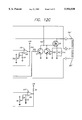
- FIG. 12 (12A-12C) is a circuit diagram for another controller circuit of the present invention.
- FIG. 13 illustrates the connection of the circuit of FIG. 12 to the coils 202 and 200 of the two solenoids 138 and 140 of FIG. 4.
- FIG. 14 (14A-14C) is a circuit diagram for a still further control circuit in accordance with the present invention.
- FIG. 15 is a copy of a strip chart showing the current waveform in an actuated solenoid and the back EMF measured on the coil of the solenoid which had previously been latched in accordance with the present invention.
- FIG. 16 is a copy of a strip chart showing the current waveform in an actuated solenoid and the back EMF measured on the coil of the solenoid which had previously been latched in accordance with the present invention for an embodiment wherein the current pulse is terminated upon arrival of the spool valve at the actuated position.
- FIG. 17 is a block diagram of one embodiment of fuel injection system in accordance with the present invention.
- FIG. 18 is a block diagram of an alternate embodiment of fuel injection system in accordance with the present invention.
- FIG. 19 is a block diagram of a circuit connected to the battery supply line for the injection system so that when the battery voltage as supplied to the injection system falls below some predetermined limit, the circuit will enable the operation of a step-up switching regulator which in turn provides a stepped up and regulated output voltage VOUT to a valve supply switching circuit.
- FIG. 20 is a circuit diagram for the block diagram of FIG. 19.
- FIGS. 21 and 22 are block diagrams of further exemplary controller systems also utilizing fuel pressure, ambient air pressure and temperature and cylinder pressures and temperatures as controller inputs,
- FIG. 23 is an exemplary graph illustrating representative operating points over the engine operating range of load and RPM for which optimum injector operating parameters may be determined from which the controller may interpolate operating parameters between test points as required during normal engine operation
- FIG. 24 is a further embodiment of fuel injection system controller of the present invention.
- FIGS. 4 and 5 show a fuel injector 50 of the present invention.
- the fuel injector 50 is typically mounted to an engine block and injects a controlled pressurized volume of fuel into a combustion chamber (not shown).
- the injector 50 of the present invention is typically used to inject diesel fuel into a compression ignition engine, although it is to be understood that the injector could also be used in a spark ignition engine or any other system that requires the injection of a fluid.
- the fuel injector 10 has an injector housing 52 that is typically constructed from a plurality of individual parts.
- the housing 52 includes an outer casing 54 that contains block members 56, 58, and 60.
- the outer casing 54 has a fuel port 64 that is coupled to a fuel pressure chamber 66 by a fuel passage 68.
- a first check valve 70 is located within fuel passage 68 to prevent a reverse flow of fuel from the pressure chamber 66 to the fuel port 64.
- the pressure chamber 66 is coupled to a nozzle 72 through fuel passage 74.
- a second check valve 76 is located within the fuel passage 74 to prevent a reverse flow of fuel from the nozzle 72 to the pressure chamber 66.
- the flow of fuel through the nozzle 72 is controlled by a needle valve 78 that is biased into a closed position by spring 80 located within a spring chamber 81.
- the needle valve 78 has a shoulder 82 above the location where the passage 74 enters the nozzle 78. When fuel flows into the passage 74 the pressure of the fuel applies a force on the shoulder 82. The shoulder force lifts the needle valve 78 away from the nozzle openings 72 and allows fuel to be discharged from the injector 50.
- a passage 83 may be provided between the spring chamber 81 and the fuel passage 68 to drain any fuel that leaks into the chamber 81.
- the drain passage 83 prevents the build up of a hydrostatic pressure within the chamber 81 which could create a counteractive force on the needle valve 78 and degrade the performance of the injector 10.
- the volume of the pressure chamber 66 is varied by an intensifier piston 84.
- the intensifier piston 84 extends through a bore 86 of block 60 and into a first intensifier chamber 88 located within an upper valve block 90.
- the piston 84 includes a shaft member 92 which has a shoulder 94 that is attached to a head member 96.
- the shoulder 94 is retained in position by clamp 98 that fits within a corresponding groove 100 in the head member 96.
- the head member 96 has a cavity which defines a second intensifier chamber 102.
- the first intensifier chamber 88 is in fluid communication with a first intensifier passage 104 that extends through block 90.
- the second intensifier chamber 102 is in fluid communication with a second intensifier passage 106.
- the block 90 also has a supply working passage 108 that is in fluid communication with a supply working port 110.
- the supply port is typically coupled to a system that supplies a working fluid which is used to control the movement of the intensifier piston 84.
- the working fluid is typically a hydraulic fluid that circulates in a closed system separate from the fuel. Alternatively the fuel could also be used as the working fluid.
- Both the outer body 54 and block 90 have a number of outer grooves 112 which typically retain O-rings (not shown) that seal the injector 10 against the engine block. Additionally, block 62 and outer shell 54 may be sealed to block 90 by O-ring 114.
- Block 60 has a passage 116 that is in fluid communication with the fuel port 64.
- the passage 116 allows any fuel that leaks from the pressure chamber 66 between the block 62 and piston 84 to be drained back into the fuel port 64.
- the passage 116 prevents fuel from leaking into the first intensifier chamber 88.
- the flow of working fluid into the intensifier chambers 88 and 102 can be controlled by a four-way solenoid control valve 118.
- the control valve 118 has a spool 120 that moves within a valve housing 122.
- the valve housing 122 has openings connected to the passages 104, 106 and 108 and a drain port 124.
- the spool 120 has an inner chamber 126 and a pair of spool ports that can be coupled to the drain ports 124.
- the spool 120 also has an outer groove 132.
- the ends of the spool 120 have openings 134 which provide fluid communication between the inner chamber 126 and the valve chamber 134 of the housing 122. The openings 134 maintain the hydrostatic balance of the spool 120.
- the valve spool 120 is moved between the first position shown in FIG. 4 and a second position shown in FIG. 5, by a first solenoid 138 and a second solenoid 140.
- the solenoids 138 and 140 are typically coupled to a controller which controls the operation of the injector.
- the first solenoid 138 When the first solenoid 138 is energized, the spool 120 is pulled to the first position, wherein the first groove 132 allows the working fluid to flow from the supply working passage 108 into the first intensifier chamber 88, and the fluid flows from the second intensifier chamber 102 into the inner chamber 126 and out the drain port 124.
- the spool 120 When the second solenoid 140 is energized the spool 120 is pulled to the second position, wherein the first groove 132 provides fluid communication between the supply working passage 108 and the second intensifier chamber 102, and between the first intensifier chamber 88 and the drain port 124.
- the groove 132 and passages 128 are preferably constructed so that the initial port is closed before the final port is opened. For example, when the spool 120 moves from the first position to the second position, the portion of the spool adjacent to the groove 132 initially blocks the first passage 104 before the passage 128 provides fluid communication between the first passage 104 and the drain port 124. Delaying the exposure of the ports, reduces the pressure surges in the system and provides an injector which has more predictable firing points on the fuel injection curve.
- the spool 120 typically engages a pair of bearing surfaces 142 in the valve housing 122.
- Both the spool 120 and the housing 122 are preferably constructed from a magnetic material such as a hardened 52100 or 440c steel, so that the hysteresis of the material will maintain the spool 120 in either the first or second. position.
- the hysteresis allows the solenoids to be de-energized after the spool 120 is pulled into position.
- the control valve operates in a digital manner, wherein the spool 120 is moved by a defined pulse that is provided to the appropriate solenoid. Operating the valve in a digital manner reduces the heat generated by the coils and increases the reliability and life of the injector.
- the first solenoid 138 is energized and pulls the spool 120 to the first position, so that the working fluid flows from the supply port 110 into the first intensifier chamber 88 and from the second intensifier chamber 102 into the drain port 124.
- the flow of working fluid into the intensifier chamber 88 moves the piston 84 and increases the volume of chamber 66.
- the increase in the chamber 66 volume decreases the chamber pressure and draws fuel into the chamber 66 from the fuel port 64.
- Power to the first solenoid 138 is terminated when the spool 120 reaches the first position.
- the second solenoid 140 When the chamber 66 is filled with fuel, the second solenoid 140 is energized to pull the spool 120 into the second position. Power to the second solenoid 140 is terminated when the spool reaches the second position. The movement of the spool 120 allows working fluid to flow into the second intensifier chamber 102 from the supply port 110 and from the first intensifier chamber 88 into the drain port 124.
- the head 96 of the intensifier piston 96 has an area much larger than the end of the piston 84, so that the pressure of the working fluid generates a force that pushes the intensifier piston 84 and reduces the volume of the pressure chamber 66.
- the stroking cycle of the intensifier piston 84 increases the pressure of the fuel within the pressure chamber 66.
- the pressurized fuel is discharged from the injector through the nozzle 72.
- the fuel is typically introduced to the injector at a pressure between 1000-2000 psi.
- the piston has a head to end ratio of approximately 10:1, wherein the pressure of the fuel discharged by the injector is between 10,000-20,000 psi.
- the double solenoid spool valve of the present invention provide a fuel injector which can more precisely discharge fuel into the combustion chamber of the engine than injectors of the prior art.
- the increase in accuracy provides a fuel injector that more closely approximates the square fuel curve shown in the graph of FIG. 3.
- the high speed solenoid control valves can also accurately supply the pre-discharge of fuel shown in the graph.
- FIG. 6 shows an alternate embodiment of a fuel injector of the present invention which does not have a return spring for the needle valve.
- the supply working passage 108 is coupled to a nozzle return chamber 150 by passage 152.
- the needle valve 78 is biased into the closed position by the pressure of the working fluid in the return chamber 150.
- the intensifier piston 84 is stroked, the pressure of the fuel is much greater than the pressure of the working fluid, so that the fuel pressure pushes the needle valve 78 away from the nozzle openings 72.
- the intensifier piston 84 returns to the original position, the pressure of the working fluid within the return chamber 150 moves the needle valve 78 and closes the nozzle 72.
- FIG. 7 shows an injector 160 controlled by a three-way control valve 162.
- the first passage 108 is connected to a drain port 164 in block 90, and the intensifier piston 84 has a return spring 166 which biases the piston 84 away from the needle valve 78. Movement of the spool 168 provides fluid communication between the second passage 106 and either the supply port 110 or the drain port 124.
- the second passage 106 When the spool 168 is in the second position, the second passage 106 is in fluid communication with the supply passage 108, wherein the pressure within the second intensifier chamber 102 pushes the intensifier piston 84 and pressurized fuel is ejected from the injector 160.
- the fluid within the first intensifier chamber 88 flows through the drain port 164 and the spring 166 is deflected to a compressed state.
- the second passage 106 is in fluid communication with the drain port 124 and the second intensifier chamber 102 no longer receives pressurized working fluid from the supply port 110.
- the force of the spring 166 moves the intensifier piston 84 back to the original position.
- the fluid within the second intensifier chamber 102 flows through the drain port 124.
- Both the three-way and four-way control valves have inner chambers 126 that are in fluid communication with the valve chamber 132 through spool openings 134, and the drain ports 124 through ports 130.
- the ports inner chamber and openings insure that any fluid pressure within the valve chamber is applied equally to both ends of the spool.
- the equal fluid pressure balances the spool so that the solenoids do not have to overcome the fluid pressure within the valve chamber when moving between positions. Hydrostatic pressure will counteract the pull of the solenoids, thereby requiring more current for the solenoids to switch the valve.
- the solenoids of the present control valve thus have lower power requirements and generate less heat than injectors of the prior art, which must supply additional power to overcome any hydrostatic pressure within the valve.
- the balanced spool also provides a control valve that has a faster response time, thereby increasing the duration interval of the maximum amount of fuel emitted by the injector. Increasing the maximum fuel duration time provides a fuel injection curve that is more square and more approximates an ideal curve.
- the ends of the spool 120 may have concave surfaces 170 that extend from an outer rim to openings 134 in the spool 120.
- the concave surfaces 170 function as a reservoir that collects any working fluid that leaks into the gaps between the valve housing 122 and the end of the spool.
- the concave surfaces significantly reduce any hydrostatic pressure that may build up at the ends of the spool 120.
- the annular rim at the ends of the spool 120 should have an area sufficient to provide enough hysteresis between the spool and housing to maintain the spool in position after the solenoid has been de-energized.
- FIG. 8 a basic valve controller in accordance with the present invention may be seen.
- This controller circuit is relatively small, and as shall subsequently be seen, results in lower system power consumption, and accordingly can be mounted directly on the injector assembly itself.
- the circuit is intended to be used with solenoids of the hereinbefore described fuel injector by connection to the coils 202 and 200 of the two solenoids 138 and 140.
- coil 200 has its leads connected to connections P1 and P2 of FIG. 8
- coil 202 has its leads connected to connections P3 and P4 of FIG. 8.
- connection J1-1 is connected to the vehicle or engine battery, typically 12 or 24 volts in the case of large diesel engines.
- Connection J1-2 is connected to the battery ground, and connection J1-3 is connected to a control source for providing a control signal to the driver circuit.
- the battery voltage on line 204 is provided to a five-volt regulator 206 which provides a five-volt supply voltage for various devices in the circuit.
- Capacitor C1 is a smoothing capacitor for the five-volt output, with resistor R2 providing a trickle load on the regulator to prevent the five-volt output from drifting upward in the relative absence of other loads.
- the voltage on line 204 is also provided through diode D1 to solenoid coil connection P1 and through diode D2 to solenoid coil connection P3.
- Capacitor C2 a relatively large capacitor, provides a smoothing effect on the battery voltage on line 204, thereby providing some protection against transients when the solenoid coils are switched in and out of circuit.
- Capacitor C5 and C6 provide a similar smoothing when the respective solenoid coil is switched in circuit.
- the remainder of the circuit of FIG. 8 is perhaps best described by following the signal flow for a typical control signal applied to the control line J1-3.
- the voltage on the control line 208 will be at the low state, either held low by the microcomputer or other digital circuit driving the same, or pulled low by the pull-down resistor R4.
- the Q output of a similar monostable multivibrator 214 will also be low, having previously returned to the low state of its prior monostable cycle.
- a typical signal format on line 208 is shown in FIG. 10.
- the monostable multivibrator 210 is triggered, driving the Q output high which in turns drives the output of the voltage translator 212 high, turning on the power n-channel device Q1.
- This essentially grounds connection P2, so that now the full battery voltage is connected across solenoid coil 200 (less one diode voltage drop of diode D1 and the on voltage drop across power device Q1) pulling the spool towards solenoid 140 (see FIG. 4) to pressurize the intensifier chamber 102 and initiate fuel injection.
- the RC combination of resistor R1 and capacitor C3 determines the length of time the monostable multivibrator 210 remains in the triggered state until returning to the quiescent state with the Q output thereof low, thereby turning n-channel power device Q1 off again to terminate current flow in coil 200.
- the pulse of the monostable multivibrator 210 is chosen to be equal to the actuating time, that is the transit time for the spool from one stable position to the opposite stable position, plus a time increment as a margin of safety to accommodate adverse extremes in battery voltage, solenoid coil resistance, temperature, etc., and further to accommodate bounce of the spool when it reaches its new position.
- the power n-channel device Q1 is turned off, terminating the temporary connection of solenoid lead P2 to ground.
- the resulting back EMF of the solenoid coil forward biases zener diode Z1, with the current in the coil rapidly diminishing to zero as the result of the energy dissipation in the voltage drop of the diode and the resistance of the coil.
- the resulting current pulse in solenoid coil 200 will be approximately as shown in FIG. 11.
- the current pulse lasts just long enough to assure that the spool travels to the opposite extreme of its travel and latches at that position to initiate injection, plus of course some time margin of comfort, after which the pulse is terminated.
- the monostable multivibrator 214 is triggered, pulsing power n-channel device Q2 on through voltage translator 216, thereby returning the spool to its initial position to terminate the injection of the fuel injector.
- the monostable multivibrator 214 will itself time out after a safe operating time for the spool as determined by resistor R3 and capacitor C4, thereby turning off power n-channel device Q2, with the resulting current pulse in coil 202 decaying rapidly through the forward biased zener Z2 during the decay period due to the back EMF of coil 202.
- a simple pulse control signal having a time period equal to the desired injection time period may be provided to the circuit of FIG. 8, with the simple control waveform being converted to a first latching current pulse to initiate injection at the beginning of the injection control signal and a second current pulse to assure latching to terminate injection at the end of the injection control pulse.
- This is to be compared with prior art solenoid actuated injectors wherein power must be applied to the injector solenoid throughout the duration of the injection control pulse. Because of this continuous application of power during injection, the prior art required solenoid operated valves of a size and power dissipation capability adequate to absorb the full solenoid actuating current for the longest injection time (or injection duty cycle) required of the injector.
- the solenoid valve of the prior art is generally required to be much larger than with the present invention, which in turn tends to slow the valve operation, resulting in a slow injection rise time and, what is particularly bad, a slow injection termination.
- full travel of the spool of the valve of the present invention injectors will be achieved at approximately 218 (FIG. 11) while the current in the respective solenoid is still rising, though power to the solenoid coil is itself terminated shortly thereafter, again while the current is still rising. If, on the other hand, the current was not terminated before the end of the pulse of FIG.
- the current would continue to rise, even in the present invention, to considerably higher levels, resulting in a much higher current for a much longer period, increasing the power dissipation to excessive levels, perhaps on the order of one to two orders of magnitude.
- either expensive, relatively large and power consuming current limiting circuitry would be required, or alternatively the drive on the solenoid would need to be reduced so that the average power consumption was tolerable, thereby very substantially reducing the speed of operation of the solenoid valve and thus of the injector. Accordingly, the valve controller circuit of FIG.
- valve 8 is a highly efficient circuit for controlling valves such as fuel injection valves, allowing high drive, very fast solenoid operating current pulses while maintaining a low total power consumption, allowing the use of small solenoids and avoiding substantial temperature rise thereof above the already quite warm environment of an operating engine.
- FIG. 12 another controller circuit illustrating another aspect of the present invention may be seen. Like the circuit of FIG. 8, this circuit operates from a low impedance battery power supply with the battery voltage applied between connector pins J1-1 and J1-2 of connector J1, and operates from a control signal on connector pin J1-3 of connector J1, the control signal being in the same form as illustrated in FIG. 10 with respect to the circuit of FIG. 8.
- the solenoid coil connections are slightly different from those shown in FIG. 9, namely the two solenoid coils 200' and 202' are connected in series as shown in FIG. 13, with the common connection J2-3 being coupled to the battery supply voltage on line 204.
- FIG. 12 provides both a more controlled release of the latched solenoid shortly after excitation of the opposite solenoid, achieving both more precise time of initiation of spool motion and a faster rising unbalanced magnetic force to decrease the transit time of the spool in the spool valve to increase the speed of injector valve operation.
- the specific circuit shown in FIG. 12 provides the foregoing described snap action only in one direction of operation of the spool valve, specifically the turning off of the injector valve in a typical fuel injection system, such as direct combustion chamber injection in a diesel engine, as a sharp cutoff is particularly advisable to minimize the amount of unburned or partially burned fuel in the engine exhaust.
- a five volt regulator 206 is connected to the battery voltage on line 204 to provide a five volt output for operation of various other circuits of the Figure.
- Capacitors C8, C12 and C13 provide noise suppression on the five volt line.
- the specific circuit shown is a clocked circuit (though a corresponding free-running circuit may also be used).
- an oscillator 300 provides a clock signal to counter-divider 302 which in turn provides a clock signal to counter-divider 304, with an appropriate clock signal on line 306 being taken from an output of either counter-divider as may be suitable for the specific application.
- the clock signal on line 306 should be sufficiently high so that the time period of one clock cycle is of no particular significance to the overall timing requirements of the system.
- the monostable multivibrator 308 will time out after a time period determined by the combination of capacitor C7, fixed resistor R29 and variable resistor R25, which time out could be used as before to drive the Q output on line 310 low to turn off the power n-channel devices Q2 and Q3 to terminate the current pulse.
- the voltage across the parallel combination of resistors R11 through R15 is coupled through resistor R16 to the positive input of comparator 318, the negative input of which is determined by the setting of variable resistor R18.
- Resistor R16 and capacitor C3 provide high frequency noise suppression to the positive input of the comparator 318, with resistor R17 and capacitor C4 providing similar high frequency noise suppression to the negative input of the comparator.
- the specific comparator used (LM339) has a grounded emitter, floating collector NPN transistor output, with resistor R19 pulling the output of the comparator high whenever the positive input to the comparator exceeds the negative input.
- the voltage across the parallel combination in resistors R11 through R15 rises, triggering the comparator at a level determined by the setting of variable resistance R18 so as to allow the pull-up resister R19 to pull the voltage on line 320 high to reset the D flip-flop 312, driving the Q output thereof on line 314 low and thus the output of voltage translator 316 low to turn off devices Q2 and Q3 based not on a time-out, but rather upon the reaching of a predetermined desired current.
- the termination of the actuation pulse based on reaching a predetermined desired solenoid actuation current as opposed to merely a predetermined time-out of the current pulse has substantial further advantages in terms of power consumption, particularly as it relates to the size of the solenoid coils and the amplitude of the current pulse which may be used without substantially heating the coils, and particularly without overheating the coils.
- the field strength pulling the spool away from the other solenoid against the force of the residual magnetism thereof is proportional to the current in the solenoid coil being actuated.
- the force is proportional to the square of the current.
- the battery voltage on line 204 may vary dependent upon the state of charge of the battery and other loads thereon, even momentary loads, and the resistance of the solenoid coils unit to unit and with temperature may vary quite significantly, the peak current attained is an excellent guarantee that the spool has pulled away from the opposite solenoid and completed its travel to the solenoid being powered.
- the battery voltage is low by ten percent, and the solenoid resistance is high by ten percent, the rise time on the current pulse generally in the form shown in FIG. 11 will be slower, so that the current pulse will be longer in time before the predetermined desired current amplitude is reached and the current pulse is terminated.
- the circuit automatically adjusts for the more widely varying parameters to limit the current pulse amplitude only to that required to assure fast and reliable operation of the spool valve of the injector.
- the current pulse width to actuate and latch a solenoid would have to be at least as long as required under the worst of conditions. Then in the case of a high battery voltage and low coil resistance, the current pulse may climb well above the predetermined necessary limit before terminating. Since the instantaneous power dissipation in the solenoid coil is proportional to the square of the current, considerable excess power will be dissipated in the solenoid coil under these conditions, providing substantial unnecessary heating of the solenoid coil. In that regard, the difference in spool valve heating between the controller of FIG. 8 and the controller of FIG. 12 when simulating fuel injection in an operating engine is substantial, the heating of the spool valve above ambient temperature being significant when operating under the controller of FIG. 8 and insubstantial when operated with the controller of FIG. 12, even when driven hard for high speed operation thereof.
- the circuit comprising devices 308', 312', 316', Q1, Q7 and 318' operate in the same manner as the corresponding unprimed numbered components hereinbefore described, the monostable multivibrator 308' being triggered on the negative going side of the control signal on line 208 (see FIG. 10 for the control signal waveform).
- the release of the spool from its latched position is delayed until the field in the solenoid being actuated builds to a substantial level, at which time it is then released, thereby providing a sort of snap action for increased operating speed.
- the monostable multivibrator 322 when the monostable multivibrator 308' is triggered, the monostable multivibrator 322 is also triggered, driving the Q output on line 324 low, thereby turning off transistor Q6 through resistor R23. Since prior to the triggering of the monostable multivibrator 322, the Q output thereof on line 324 was high, thereby holding transistor Q6 on through resistor R23, the gate of the power n-channel device Q4 had been held low, thereby holding the device off. Similarly, the power n-channel devices Q2 and Q3 were also off, the actuating current pulse for coil 200' being terminated before this time.
- variable resistor R22 are substantially higher than the corresponding parallel combination of resistors R1 through R5.
- the current pulse in coil 202' is rapidly rising, a corresponding current pulse in coil 200' is rising at a lower rate.
- the magnetic gap in the solenoid powered by coil 200' is substantially zero, whereas the magnetic gap in the solenoid powered by coil 202' is at a maximum, the magnetic field in the solenoid powered by the coil 200' may be caused to build from the residual field at as high or higher a rate than the field in the solenoid powered by the coil 202'.
- the spool will remain latched as the field and thus the force in the solenoid powered by coil 202' rises to quite a substantial level.
- the voltage drop across resistors R10, R21 and R22 will become adequate to start to turn on transistor Q5, pulling the gate voltage of power n-channel device Q4 lower so as to limit the current therethrough and thus through coil 200' to a level adequate to hold the base voltage of transistor Q5 at 1 VBE above ground.
- monostable multivibrator 308' will itself time out, after which the next clock cycle will turn off power n-channel devices Q1 and Q7 to terminate the current pulse in coil 202' after the spool has been latched in its new position.
- the circuit of FIG. 12 does not include the back EMF suppression zener diodes Z1 and Z2 of the circuit of FIG. 8.
- Back EMF protection is provided, however, by the power n-channel devices themselves, the IRF540 devices effectively having back EMF zeners therein.
- the zener diodes in the circuit of FIG. 8 are forward biased by the back EMF so that the current pulse tails decline slower than necessary, whereas the internal zener devices in the power n-channel devices of FIG. 12 only conduct in the reverse direction across the zener voltage, causing a more rapid declining current pulse tail.
- each zener diode of FIG. 8 might be replaced by two zeners in series and connected in opposite polarity to achieve a more rapid current pulse termination.
- FIG. 14 a still further embodiment of the present invention may be seen.
- This embodiment illustrates a still further aspect of the invention.
- the opposite solenoid is used to sense the position of the valve spool so that the actuating current pulse may be terminated upon arrival of the spool at the actuated position, or a short time thereafter after any bounce has decayed.
- this embodiment is microprocessor or single chip microcomputer controlled, so that depending upon the programming thereof injector valve control may be effected through the input to the processor of a control signal such as that illustrated in FIG.
- the circuit of FIG. 14 illustrates a control circuit for a single injector valve, though obviously aspects of the circuit can be replicated for multiple valve applications using other processor or microcomputer output lines for the control thereof.
- the circuit illustrated in FIG. 14 utilizes the same solenoid coil connections as the circuit of FIG. 12, namely that. shown in FIG. 13.
- an Intel 8751 single chip computer 400 operating under program control is used.
- the clock for the computer is referenced to an external crystal oscillator comprising crystal X1 and capacitor C1 and C2.
- the RC circuit comprising resistor 2 and capacitor 3 provides the appropriate reset pulse on start-up of the computer.
- the specific: embodiment shown is intended to operate in response to the control signal of FIG. 10 applied to the J1 connector lead J1-3.
- That input signal on line 208 is inverted twice by NAND gates 402 and 404 to apply the signal at appropriate signal levels to one lead of one of the ports of the computer configured as an input port for that purpose.
- Two leads of another port configured as an output port provide signals on lines 406 and 408 to control voltage translation devices 410 and 412, respectively, which in turn turn on and off power n-channel devices Q1 and Q3, respectively, to provide the desired current pulses to solenoid coils 200' and 202', respectively.
- the circuit comprised of resistor R5, transistors Q7 and Q6, resistors R3, R4 and R6, and power n-channel device Q5 functionally duplicates the circuit of FIG. 12 comprising resistor R23, transistors Q6 and Q5, resistors R22, R21, R10 and R32, and power n-channel device Q4 of FIG. 12, providing the snap action hereinbefore described.
- this snap action allows the previously actuated solenoid to initially hold the valve spool until the newly actuated solenoid achieves a relatively high force level, at which time the spool will be released, thereby improving the speed of operation of the valve and repeatability with time and unit to unit.
- the processor drives the voltage on line 416 low again, turning on transistor Q10 and turning off power n-channel device Q8 to initiate valve spool motion.
- the holding current in coil 202' rapidly decays, there is still a substantial field strength in the respective magnetic parts of the solenoid because of the absence of a non-magnetic gap in the respective magnetic circuit.
- the field starts to diminish, generating a voltage across coil 202' equal to Nd.o slashed./dt.
- the rate of collapse of the field in what had been the holding solenoid is accelerated because of the existence of an increasing non-magnetic gap in the respective magnetic circuit.
- the coupling from the excitation of the opposite solenoid will be relatively low, particularly as the spool approaches the end of its travel because of the now small and decreasing magnetic gap in the excited solenoid and the relatively large nonmagnetic gap in the solenoid having a substantially open coil.
- the valve spool stops at its final position what small residual magnetic field remains in the non-excited solenoid becomes stable so that the rate of change of field strength through coil 202' suddenly slows tremendously.
- FIG. 15 a strip chart showing the current waveform 420 in an actuated solenoid and the back EMF 422 measured on the coil of the solenoid which had previously been latched may be seen.
- the current 420 initially rises, the spool remains in the latched position. Once the spool pulls away from the latched position and begins moving, an increasing back EMF 422 is generated in the coil of what had been the latched solenoid. That back EMF continues to increase until it reaches a peak at the time of arrival of the spool in the new latched position, at which time the back EMF rapidly decreases.
- the peak in the back EMF 422 was used to terminate the drive voltage and thus current 420 in the excited solenoid, though even if the current 420 was continued thereafter for a period, the decaying back EMF once the valve spool reaches the new latch position will still be similar to that shown in FIG. 15. Accordingly, the peak in the back EMF curve 422 may be used as a direct indication of the arrival of the spool at the new latched position, with the current pulse to the other solenoid being terminated at that time, or preferably a short time thereafter tc allow for the settling of any bounce of the spool at its new position.
- the peak in the back EMF of solenoid coil 200' of solenoid 140 is sensed by the circuit comprising capacitors C4, C5 and C3, resistors R8, R9, R10, R11, R12, R13 and variable resistor R23, comparators 440 and 442, NAND gate 444 and diodes DI through D4.
- diodes D1 and D2 clamp the positive input to comparator 440 to a voltage range of no less than one forward conduction diode voltage drop below circuit ground to no more than one forward conduction diode voltage drop above the five volt power supply.
- Diodes D3 and D4 limit the voltage range of the negative input of comparator 442 to one forward conduction diode voltage drop below circuit ground to one forward conduction diode voltage drop above circuit ground. Both of these voltage ranges extend beyond the voltage range of the opposite input to the respective comparator, and accordingly the diodes do not affect the inputs to the comparators around their switching point.
- capacitor C5 When the back EMF of solenoid coil 200' is low or substantially zero and substantially unchanging, capacitor C5 will discharge through resistors R9 and R10 so that the positive input to comparator 440 will be substantially at ground.
- the negative input on the other hand, will be at some voltage above ground by an amount dependent upon the adjustment of variable resistor R23. Accordingly, the output transistor of the comparator 440 will be turned on, holding the output of the comparator low against the pull-up resistor R12. This assures that one input to NAND gate 444 is low, making the output of the NAND gate 444 high independent of the other input thereto, which output is coupled back to the processor or single chip computer 400 as an input signal thereto.
- capacitor C3 couples the rising voltage through resistor R8 to the negative input of comparator 442, assuring now that the output of comparator 442 is held low, thereby assuring that the output of NAND gate 444 remains held high irrespective of the output of comparator 440.
- capacitor C4 couples the rising back EMF to the positive input of comparator 440, capacitor C5 being a relatively small capacitor primarily for noise suppression purposes.
- capacitor C3 and resistor R8 act as a differentiator in the frequency range of interest, holding the negative input to comparator 442 above ground when the back EMF is increasing, but pulling the same negative when the back EMF goes over the top of the curve shown FIG. 15 and begins any decrease, thereby acting as a peak detector.
- capacitor C3 When the back EMF does go over the top and decreases at all, capacitor C3 will pull the negative input to comparator 442 low, turning off the output transistor of comparator 442 and allowing pull-up resistor R11 to pull the second input of NAND gate 444 high. Assuming the rise in the back EMF has been fast enough and high enough to properly indicate spool motion as herein before described, both inputs to NAND gate 442 will be high immediately after the back EMF has peaked, thereby driving the output of NAND gate 444 low to signal the processor or single chip computer that spool motion has been sensed and that the spool has arrived at the extreme of its travel.
- the processor may then use this signal to turn off the actuating current pulse on coil 202' by driving the voltage on line 408 low, either immediately after sensing the arrival of the valve spool at the fully actuated position as in FIG. 15, or alternatively a short time thereafter to allow for any bounce to settle to assure proper latching by way of the retentivity of the magnetic materials.
- each actuating current pulse may be quickly yet reliably terminated upon arrival off the valve spool at the newly actuated position to minimize heating in the solenoids independent of operating conditions and parameters, thereby allowing a small solenoid valve and a high operating current pulse to minimize the operating time for the spool valve without substantial heating and particularly overheating of the relatively small solenoid coils.
- the processor or single chip computer 400 control the various aspects of the operation of the spool valve, but that it essentially monitors the operation thereof also. Accordingly, the computer may also accomplish other tasks.
- the computer can recognize the lack of arrival of the spool at an actuated position within a predetermined maximum time period and shut off the current pulse even though the valve has not yet responded, thereby avoiding overheating and possible burnout of the solenoid coil. It can also sense the repetition of such an occurrence and temporarily or permanently stop attempting to actuate the spool valve pending replacement of the spool valve or entire injector.
- the computer can obviously identify the offending valve. Further, since the computer knows when it initiated a solenoid actuating current pulse, and the computer is again signaled when this spool motion is complete, the computer can determine the length of time it took for the actuation, and compare that time to a standard time for present operating conditions, or monitor the short term variations in the length of actuation time of each spool valve controlled by the computer.
- the computer can maintain performance statistics which can be interrogated and used at the time of planned engine maintenance to avoid the necessity of later unplanned maintenance.
- FIG. 17 a block diagram of one embodiment of fuel injection system in accordance with the present invention may be seen.
- This fuel injection system primarily intended for multiple cylinder engines, utilizes a master controller responsive to various inputs to provide control signals to individual controllers which in turn control an associated injector.
- the master controller would normally be responsive to such inputs as the throttle setting, the engine speed, engine temperature, ambient air temperature and crankshaft position to establish the timing of the start and duration of injection for each cylinder.
- the master controller would provide control signals generally in the form shown in FIG. 10, with individual controllers of the general type illustrated in FIG. 12, or other embodiments described herein or variations thereof, being responsive to the control signal to control the associated injector.
- the entire controller may be mounted on the injector, or as a first alternative, the power drive electronics may be mounted on the injector (or spool valve therefor) with the single chip computer being mounted in a separate control box controlled by the master controller. Also, as indicated in the figure, while the master controller controls the individual controllers which in turn control the respective injectors, the injectors may in turn feed back information to the individual controllers with respect to the required time of actuation for the spool valve therein.
- the individual controllers may use the time of actuation for the spool valves to accumulate statistics on injector operation for communicating back to the master controller, which may be interrogated through a diagnostics port on the master controller either continuously for display or recording, or periodically at the time of scheduled engine service.
- the individual controller could merely pass on these spool valve operating time periods to the master controller, with the statistics thereon being determined and maintained at the master controller for diagnostic purposes.
- the advantage of the configuration of FIG. 17 is that the individual controllers operate from a control signal waveform which is the same as the normal drive to prior art solenoid actuated injector valves wherein the solenoid is excited for the full duration of the valve injection period. While the normal drive for a prior art solenoid valve would normally be of a higher voltage, the waveform could be easily clipped, limited or otherwise translated to the input voltage range of a single chip computer or other drive circuit being used, so that injectors with individual controllers could potentially be used in direct substitution of prior art solenoid operated injection valves.
- a single more powerful central controller may be used as shown in FIG. 18.
- a single central computer monitors the various parameters determining injection time and duration and controls the drive electronic for the spool valves of the individual injectors, the spool valves in turn providing their own performance data back to the controller for display through a diagnostic system and/or later retrieval by the diagnostic system.
- FIG. 11 shows the current pulse in one coil to actuate the spool valve and latch the same so as to initiate injection, and the current pulse in the opposite coil to return the spool valve to the original position and latch the same to terminate injection.
- These current pulses can be closely spaced in time, or even be somewhat overlapping, to have an initial very short injection period, then followed by the full injection cycle again to provide the pre-injection followed by normal injection.
- controllers of the present invention may sense the time required for full actuation of the spool valve, either as measured from the beginning of the actuating pulse, or in the case of snap action, from the termination of the holding current allowing release of the spool valve to initiate actuation. This time of spool valve actuation may be measured during the normal injection cycle (as opposed to during pre-injection).
- Battery voltage in a properly operating engine system will remain within reasonable limits, and the present invention is particularly tolerant of battery voltage variations because of its ability to terminate the spool valve actuating current pulse as soon as spool valve motion is complete and latching has been achieved.
- battery voltage during engine starting can drop drastically, though good control of injection during starting of an engine, particularly a cold engine, is still desired.
- a boost voltage circuit may be utilized when the battery voltage drops below some predetermined voltage, such as below a normal operating voltage indicative of the operation of the starter motor.
- a low voltage detection circuit is connected to the battery supply line for the injection system.
- the output of the low voltage detection circuit will enable the operation of a step-up switching regulator which in turn provides a stepped up and regulated output voltage VOUT to a valve supply switching circuit.
- Step-up switching regulators in general provide a constant output voltage VOUT independent of the input voltage, and are capable of proper operation from a small step-up in voltage to stepping up of the input voltage thereto by a substantial multiple.
- one of the advantages of the present invention is the fact that the average power required for actuation of the spool valves is relatively low, a very small fraction of that required by prior art solenoid controlled injection valves, so that the power capabilities required of the step-up switching regulator used with the present invention is relatively modest, particularly considering that the same may be operating the fuel injectors for a relatively large diesel engine.
- FIG. 20 A full circuit of the type shown in FIG. 19 may be seen in FIG. 20.
- a current supplied by resistor 500 through a voltage source 502 is provided as the positive input to comparator 504.
- Voltage source 502 may be a zener diode or other voltage source as are readily commercially available.
- the negative input to comparator 504 is provided by voltage divider comprising resistors 506 and 508. In operation, voltage source 502 holds the positive input to the comparator at the voltage of the voltage source. If the battery voltage is sufficiently high, the divided down voltage on the negative input to the comparator 504 will still be higher than the voltage of voltage source 502 to hold the output of the comparator on line 510 low.
- voltage source 502 will hold the positive input to the comparator at the voltage of the voltage source, whereas the voltage on the negative input will decrease in proportion to the decrease in the battery voltage until finally the positive input to the comparator 504 is higher than the negative input, driving the output of the comparator on line 510 high. If the battery voltage drops below the voltage of voltage source 502, the voltage source will shut off. Now the voltage on the positive input to the comparator will be substantially equal to the battery voltage, though the negative input to comparator 504 will be a voltage divided down from the battery voltage, so that the positive input to the comparator is still higher than the negative input, so that the comparator still holds line 510 high.
- the voltage from line 510 provides an enable signal to the switching step-up regulator 512, in the embodiment shown a pulse width modulation switching regulator integrated circuit.
- switching regulators of various types, including pulse width modulation and frequency modulation regulators, are well known in the prior art of electronics and need not be described further herein).
- the output of the pulse width modulation switching regulator integrated circuit is coupled through line 514 to the base of transistor 516.
- the pulse width modulator 512 When the pulse width modulator 512 is enabled as a result of low battery voltage, the output of the pulse width modulator 512 will turn transistor 516 on and off at a constant frequency, but with a duty cycle as required to maintain the voltage on line 518 at the predetermined desired level as sensed by the feedback on line 520 to the pulse width modulator.
- transistor 516 when transistor 516 is turned on, the current in inductor 522 rises linearly, building up energy in the magnetic field of the inductor.
- transistor 516 When transistor 516 is turned off, the back EMF of inductor 522 forward biases diode 524 to provide a charging current pulse to capacitor 526 which in turn delivers current to the valves through diode 528.
- diode 524 If the electrical load on such a system is relatively low, transistor 516 will be turned on with a relatively low duty cycle, so that little energy builds in inductor 522 before the transistor is turned off. As this energy is delivered to capacitor 526 through diode 524, the current in inductor 522 will again fall to zero, diode 524 thereafter preventing reverse current flow from the output back to the battery.
- transistor 516 may be turned on with a much higher duty cycle so that when transistor 516 is turned off, a higher current pulse is delivered to capacitor 526 through diode 524, with transistor 516 being turned on again to again replenish the energy in the inductor even before the inductor current falls to zero.
- switching regulators of a reasonable size may be used to step up a battery terminal voltage of only a few volts to the full desired operating voltage of the system. This assures performance of the injection system at any battery voltage adequate to turn over the engine for starting purposes.
- the negative input to comparator 504 will exceed the positive input thereto, driving the enable voltage on line 510 low to turn off the pulse width modulator 512.
- the current through inductor 522 will be zero, as the forward conduction voltage drop of diode 520 will be less than the forward conduction diode voltage drop required by the two diodes 524 and 528.
- pre-injection initiates combustion, so that main combustion begins on the beginning of main injection, effectively eliminating the combustion delay causing knocking and which delay has been found to increase NO x emissions. Consequently the timing of pre-injection with respect to main injection is very important.
- Pre-injection too close to main injection will not fully eliminate the delay of the onset of main combustion, yet pre-injection too early can cause nearly complete combustion of the pre-injected fuel, so that again main combustion is not initiated immediately on the initiation of main injection.
- the best delay between pre-injection and main injection is relatively independent of engine speed, though one of the advantages of the present invention is the ability to accurately control all parameters of pre-injection and the relationship between pre-injection and main injection to optimize engine operation under varying operating conditions.
- the desired delay between pre-injection and main injection is on the order of 250 microseconds, so speed of operation of the valves and controllers of the present invention is essential to achieving the desired result. Also it is desired to vary not only the delay timing, but also the amount of pre-injection dependent on engine operating conditions and even environmental conditions, as a cold engine my call for a longer delay, an idling engine for less pre-injection, etc.
- pre-injection may be accomplished by latching the valve in the injection position and very quickly providing the opposite latching pulse to turn off the injection.
- the actuating current pulse may be terminated before the spool travel is complete and the same latches in the injection position.
- the actuating current pulse will be terminated before the spool travel is complete and the current pulse terminating injection will be initiated, either just after the actuating current pulse is terminated, or even just before the actuating current pulse is terminated so that there is some slight overlap between the two pulses. Since main injection begins very shortly after pre-injection, the spool valve may not latch at the injection off position before the pulse initiating main injection occurs. Even here however, the pulse initiating main injection may slightly overlap the pulse terminating pre-injection if desired to provide a snap action at the beginning of main injection, as a snap action will still be achieved without latching because the current pulses are of equal amplitude and the spool valve will be closer to the injection off position.
- Another way to control pre-injection is to sense the beginning of pre-injection by sensing some parameter directly responsive to pre-injection.
- a pressure transducer has been used at the outlet of the pressurized fuel supply supplying the injectors. Initiation and termination of pre-injection can be sensed by a sudden drop in pressure and a sudden rise in pressure, respectively.
- initiation of pre-injection has been sensed this way with test injectors in accordance with the present invention, with the rest of the pre-injection and main injection cycles being controlled as described above.
- Still another way to control pre-injection is to sense cylinder pressure for each cylinder of the engine, such as by use of a strain gauge transducer. While this would require multiple transducers operating in an adverse environment, it would not only allow sensing the pressure rise due to pre-injection, but would also provide information on balance between cylinders for pre-injection, main injection and compression itself, and information from which such balance could be maintained, and would provide very useful diagnostic information for maintaining peak engine performance.
- injectors may each be characterized at the time of manufacture as to certain parameters unique to that injector, such as injection flow rate, parameters effecting speed of operation, etc. and each injector marked with a letter code or other code indicative of these parameters.
- the injection system controller would be given the code for each injector so that the controller will match each injector with the appropriate control parameters.
- injector characterization may be done on test equipment set up for that purpose, or even on an operating engine (typically a single cylinder engine) so that pressure traces may be taken, efficiency maximized and noise, emissions, etc. may be measured and minimized by the characterization of the injectors.
- Exemplary controller systems utilizing fuel pressure and cylinder pressures are shown in block diagram form in FIGS. 21 and 22, respectively. Also shown in these Figures is the use of cylinder temperatures instead of or in addition to overall engine temperature.
- Cylinder temperatures may be measured by thermocouple-type or other temperature sensors, and are useful not only for cylinder balancing purposes, but also as providing an indication of combined effects of engine operating conditions (engine temperature, load, etc.) and environmental conditions (ambient air temperature). Also shown is the use of ambient air pressure, useful to limit the maximum amount of main fuel injection in relation to the total amount of air being ingested for combustion.
- the speed of the present invention injection system and the flexibility of the control system allow the control of various parameters under varying operating conditions, even on intensifier type injectors. Obviously, control of the duration of main injection provides the basic power control. In addition however, it is contemplated that the ultimate control will be determined by operating a representative engine at various combinations of load and RPM and determining the best parameters for optimum performance for each combination of load and RPM tested. It is possible that parameters for city driving would be purposely different from those for country driving, as noise is much more of a problem in city operation than in country operation.
- Parameters that will be varied may include the pre-injection initiating current pulse width, the time the spool valve is held open on pre-injection, the total duration the pre-injection and how far the initiating and terminating pulses are separated in time or how much they overlap, and the timing between pre-injection and main injection. It is contemplated that these, and perhaps other parameters be determined at representative operating points over the full engine operating range of load and RPM, such as shown in FIG. 23, and that the controller interpolate each parameter between test points as required during normal engine operation (test points may be out of the normal operating range for interpolation purposes even though the injector control system may prevent normal engine operations at such extremes).
- FIG. 24 a further embodiment of fuel injection system controller of the present invention may be seen.
- This embodiment differs from the embodiment of FIG. 14 only in that one side of each solenoid coil is grounded, rather than being tied high as in the embodiment of FIG. 14. Since the operation of this embodiment is the same as that of FIG. 14, the prior detailed description of such operation will not be repeated herein, the circuit being presented however, as the same is now preferred over the embodiment of FIG. 14.
- microprocessor is used in the general sense to refer to what are sometimes referred to as microprocessors, microcontrollers and single chip computers.
Abstract
Description
Claims (48)
Priority Applications (1)
| Application Number | Priority Date | Filing Date | Title |
|---|---|---|---|
| US08/565,414 US5954030A (en) | 1994-12-01 | 1995-11-30 | Valve controller systems and methods and fuel injection systems utilizing the same |
Applications Claiming Priority (2)
| Application Number | Priority Date | Filing Date | Title |
|---|---|---|---|
| US08/348,537 US5720261A (en) | 1994-12-01 | 1994-12-01 | Valve controller systems and methods and fuel injection systems utilizing the same |
| US08/565,414 US5954030A (en) | 1994-12-01 | 1995-11-30 | Valve controller systems and methods and fuel injection systems utilizing the same |
Related Parent Applications (1)
| Application Number | Title | Priority Date | Filing Date |
|---|---|---|---|
| US08/348,537 Continuation-In-Part US5720261A (en) | 1994-12-01 | 1994-12-01 | Valve controller systems and methods and fuel injection systems utilizing the same |
Publications (1)
| Publication Number | Publication Date |
|---|---|
| US5954030A true US5954030A (en) | 1999-09-21 |
Family
ID=23368460
Family Applications (2)
| Application Number | Title | Priority Date | Filing Date |
|---|---|---|---|
| US08/348,537 Expired - Lifetime US5720261A (en) | 1994-12-01 | 1994-12-01 | Valve controller systems and methods and fuel injection systems utilizing the same |
| US08/565,414 Expired - Lifetime US5954030A (en) | 1994-12-01 | 1995-11-30 | Valve controller systems and methods and fuel injection systems utilizing the same |
Family Applications Before (1)
| Application Number | Title | Priority Date | Filing Date |
|---|---|---|---|
| US08/348,537 Expired - Lifetime US5720261A (en) | 1994-12-01 | 1994-12-01 | Valve controller systems and methods and fuel injection systems utilizing the same |
Country Status (8)
| Country | Link |
|---|---|
| US (2) | US5720261A (en) |
| EP (1) | EP0803026B1 (en) |
| JP (1) | JPH10510607A (en) |
| AU (1) | AU4506596A (en) |
| DE (1) | DE69525179T2 (en) |
| GB (1) | GB2311818B (en) |
| HK (1) | HK1016239A1 (en) |
| WO (1) | WO1996017167A1 (en) |
Cited By (133)
| Publication number | Priority date | Publication date | Assignee | Title |
|---|---|---|---|---|
| US6053150A (en) * | 1998-03-31 | 2000-04-25 | Isuzu Motors Limited | Fuel-injection system for engines |
| WO2000023704A1 (en) * | 1998-10-16 | 2000-04-27 | International Truck And Engine Corporation | Fuel injector with direct needle valve control |
| WO2001029409A1 (en) * | 1999-10-22 | 2001-04-26 | Robert Bosch Gmbh | Injection device and method for injection of fluids |
| US6269784B1 (en) * | 2000-04-26 | 2001-08-07 | Visteon Global Technologies, Inc. | Electrically actuable engine valve providing position output |
| US6293252B1 (en) * | 1999-04-14 | 2001-09-25 | Hydraulik-Ring Gmbh | Fuel injection device for internal combustion engines |
| US6390058B1 (en) * | 1999-08-03 | 2002-05-21 | Isuzu Motors Limited | Engine fuel injection control device |
| US6415749B1 (en) | 1999-04-27 | 2002-07-09 | Oded E. Sturman | Power module and methods of operation |
| US20020118057A1 (en) * | 1999-08-31 | 2002-08-29 | Leonard Forbes | Integrated circuit and method for minimizing clock skews |
| WO2002075139A1 (en) * | 2001-03-15 | 2002-09-26 | Siemens Vdo Automotive Corporation | End of valve motion detection for a spool control valve |
| US6474304B1 (en) | 1999-05-18 | 2002-11-05 | International Engine Intellectual Property Company, L.L.C. | Double-acting two-stage hydraulic control device |
| US6516658B1 (en) * | 1999-04-16 | 2003-02-11 | Siemens Vdo Automotive Corporation | Identification of diesel engine injector characteristics |
| US6526943B2 (en) | 2001-01-17 | 2003-03-04 | Siemens Diesel Systems Technology, Llc | Control valve for hydraulically oil activated fuel injector |
| US20030048161A1 (en) * | 1999-12-15 | 2003-03-13 | Brian Johnson | Battery cut-off device and method |
| US20030155437A1 (en) * | 2002-02-05 | 2003-08-21 | Ning Lei | Fuel injector with dual control valve |
| US6651629B2 (en) | 2001-01-04 | 2003-11-25 | Mccoy John C. | Internal energizable voltage or current source for fuel injector identification |
| US6662783B2 (en) * | 2001-10-22 | 2003-12-16 | Siemens Diesel Systems Technology | Digital valve |
| US6684854B2 (en) | 2001-12-14 | 2004-02-03 | Caterpillar Inc | Auxiliary systems for an engine having two electrical actuators on a single circuit |
| US6715694B2 (en) * | 2001-07-06 | 2004-04-06 | Siemens Diesel Systems Technology | Control valve body for an oil activated fuel injector |
| US6722628B1 (en) | 2003-02-06 | 2004-04-20 | Sturman Industries, Inc. | Miniature poppet valve assembly |
| EP1412721A1 (en) * | 2001-07-31 | 2004-04-28 | Diesel Technology Company | Method for determinig fuel injection rate shaping current in an engine fuel injection system |
| US6729302B2 (en) * | 2001-04-06 | 2004-05-04 | Mtu Friedrichshafen Gmbh | Fuel injection system for an internal-combustion engine |
| US6836224B1 (en) | 1999-11-01 | 2004-12-28 | Siemens Vdo Automotive Corporation | Method for assigning coded incremental values |
| US20050121535A1 (en) * | 2002-06-11 | 2005-06-09 | Volkswagen Mechatronic Gmbh & Co. Kg | Method and device for measuring and regulating the closing and opening times of a piezo control valve |
| US20050150980A1 (en) * | 2001-01-17 | 2005-07-14 | Ulrich Augustin | Oil activated fuel injector control with delay plunger |
| US20050263621A1 (en) * | 2002-07-29 | 2005-12-01 | Achim Brenk | Fuel injector with and without pressure ampification with a controllable needle speed and method for the controlling thereof |
| US20050284950A1 (en) * | 2002-10-30 | 2005-12-29 | Shigeru Yamazaki | Fuel injection method |
| US20060035791A1 (en) * | 2003-10-10 | 2006-02-16 | R.T. Vanderbilt Company, Inc. | Lubricating compositions containing synthetic ester base oil, molybdenum compounds and thiadiazole-based compounds |
| US7000599B2 (en) | 2004-07-26 | 2006-02-21 | Techlusion Corporation | Supplemental fuel injector trigger circuit |
| US20060192028A1 (en) * | 2005-02-28 | 2006-08-31 | Sturman Industries, Inc. | Hydraulically intensified injectors with passive valve and methods to help needle closing |
| US20060202053A1 (en) * | 2005-03-09 | 2006-09-14 | Gibson Dennis H | Control valve assembly and fuel injector using same |
| US20060219497A1 (en) * | 2005-03-30 | 2006-10-05 | Organek Gregory J | Residual magnetic devices and methods |
| US20060219498A1 (en) * | 2005-03-30 | 2006-10-05 | Organek Gregory J | Residual magnetic devices and methods |
| US20060219496A1 (en) * | 2005-03-30 | 2006-10-05 | Dimig Steven J | Residual magnetic devices and methods |
| US20060219499A1 (en) * | 2005-03-30 | 2006-10-05 | Organek Gregory J | Residual magnetic devices and methods |
| US20060219513A1 (en) * | 2005-03-30 | 2006-10-05 | Organek Gregory J | Residual magnetic devices and methods |
| US20060227488A1 (en) * | 2005-03-30 | 2006-10-12 | Dimig Steven J | Residual magnetic devices and methods |
| US20060226942A1 (en) * | 2005-03-30 | 2006-10-12 | Dimig Steven J | Residual magnetic devices and methods |
| US20060225985A1 (en) * | 2005-03-30 | 2006-10-12 | Dimig Steven J | Residual magnetic devices and methods |
| US20060225707A1 (en) * | 2003-04-24 | 2006-10-12 | Gerhard Eser | Method for controlling a fuel pressure in a fuel supply device of a combustion engine |
| US20060226939A1 (en) * | 2005-03-30 | 2006-10-12 | Dimig Steven J | Residual magnetic devices and methods |
| US20060226941A1 (en) * | 2005-03-30 | 2006-10-12 | Dimig Steven J | Residual magnetic devices and methods |
| US20060238284A1 (en) * | 2005-03-30 | 2006-10-26 | Dimig Steven J | Residual magnetic devices and methods |
| US20060237959A1 (en) * | 2005-03-30 | 2006-10-26 | Dimig Steven J | Residual magnetic devices and methods |
| US20060238285A1 (en) * | 2005-03-30 | 2006-10-26 | Dimig Steven J | Residual magnetic devices and methods |
| US20070012283A1 (en) * | 2005-07-14 | 2007-01-18 | Rockwell Andrew D | Internal combustion engine start-up operating mode and engine using same |
| US20070090315A1 (en) * | 2005-10-20 | 2007-04-26 | Siemens Ag | Method for checking a valve |
| US20070095934A1 (en) * | 2005-10-18 | 2007-05-03 | Siemens Vdo Automotive Corporation | Horizontal spool for direct needle closing |
| US20070137620A1 (en) * | 2005-12-21 | 2007-06-21 | Couch David K | Fuel injection performance enhancing controller |
| US20070188742A1 (en) * | 2003-03-31 | 2007-08-16 | Gunsaulis Floyd R | System for detecting deflection of a boring tool |
| US20070245982A1 (en) * | 2006-04-20 | 2007-10-25 | Sturman Digital Systems, Llc | Low emission high performance engines, multiple cylinder engines and operating methods |
| US20080083895A1 (en) * | 2006-09-20 | 2008-04-10 | Denso Corporation | Apparatus for driving electromagnetic values |
| US20080087738A1 (en) * | 2006-10-17 | 2008-04-17 | Sturman Digital Systems, Llc | Fuel injector with boosted needle closure |
| US20080087254A1 (en) * | 2006-10-06 | 2008-04-17 | Denso Corporation | Solenoid operated valve device designed to ensure high responsiveness of valve action |
| US20080099515A1 (en) * | 2006-10-11 | 2008-05-01 | Nordson Corporation | Thin line conformal coating apparatus and method |
| US20080127919A1 (en) * | 2006-12-05 | 2008-06-05 | Allan Gale | Operation of electrically actuated valves at lower temperatures |
| US20080127918A1 (en) * | 2006-12-05 | 2008-06-05 | Richard Wineland | Method for improving operation of an electrically operable mechanical valve |
| US20080127940A1 (en) * | 2006-12-05 | 2008-06-05 | Craig Stephan | System and method for reducing power consumption when heating a fuel injector |
| US20080127951A1 (en) * | 2006-12-05 | 2008-06-05 | Allan Gale | System and method for improving operation of a fuel injector at lower temperatures |
| US20080132380A1 (en) * | 2006-12-05 | 2008-06-05 | Clay Maranville | Operation of electrically controlled transmissions at lower temperatures |
| US20080163939A1 (en) * | 2007-01-05 | 2008-07-10 | Mac Valves, Inc. | Valve assembly with dual actuation solenoids |
| US7412969B2 (en) | 2006-03-13 | 2008-08-19 | Sturman Industries, Inc. | Direct needle control fuel injectors and methods |
| US20080203183A1 (en) * | 2007-02-26 | 2008-08-28 | Larry Elie | Method for controlling an electrical actuator |
| US20080243354A1 (en) * | 2007-03-30 | 2008-10-02 | Caterpillar Inc. | Prediction based engine control system and method |
| US20080264393A1 (en) * | 2007-04-30 | 2008-10-30 | Sturman Digital Systems, Llc | Methods of Operating Low Emission High Performance Compression Ignition Engines |
| US20090026985A1 (en) * | 2006-01-26 | 2009-01-29 | Knorr-Bremse Systeme Fuer Nutzfahrzeuge Gmbh | Method for Actuating an Electromagnetic Valve |
| US20090139490A1 (en) * | 2007-12-03 | 2009-06-04 | Continental Automotive System Us, Inc. | Control method for closed loop operation with adaptive wave form of an engine fuel injector oil or fuel control valve |
| US20090183699A1 (en) * | 2008-01-18 | 2009-07-23 | Sturman Digital Systems, Llc | Compression Ignition Engines and Methods |
| US7594502B1 (en) | 2005-12-07 | 2009-09-29 | Anderson Joel A | Projectile loading, firing and warning system |
| US7596445B2 (en) | 2007-02-26 | 2009-09-29 | Ford Global Technologies, Llc | Method for improving the operation of electrically controlled actuators for an internal combustion engine |
| US20100012745A1 (en) * | 2008-07-15 | 2010-01-21 | Sturman Digital Systems, Llc | Fuel Injectors with Intensified Fuel Storage and Methods of Operating an Engine Therewith |
| US20100186716A1 (en) * | 2007-05-09 | 2010-07-29 | Sturman Digital Systems, Llc | Multiple Intensifier Injectors with Positive Needle Control and Methods of Injection |
| US7954472B1 (en) | 2007-10-24 | 2011-06-07 | Sturman Digital Systems, Llc | High performance, low emission engines, multiple cylinder engines and operating methods |
| US20110251777A1 (en) * | 2010-04-08 | 2011-10-13 | Delphi Technologies, Inc. | System and Method for Controlling an Injection Time of a Fuel Injector Based on Closing Electrical Decay |
| US20120186558A1 (en) * | 2011-01-21 | 2012-07-26 | International Engine Intellectual Property Company, Llc | Electric-actuated control valve of a unit fuel injector |
| WO2013019446A2 (en) | 2011-07-29 | 2013-02-07 | Sturman Digital Systems, Llc | Digital hydraulic opposed free piston engines and methods |
| US8478509B1 (en) | 2009-08-07 | 2013-07-02 | William E. Kirkpatrick | Method and apparatus for varying the duration of a fuel injector cycle pulse length |
| WO2013158070A1 (en) * | 2012-04-16 | 2013-10-24 | International Engine Intellectual Property Company, Llc | Injector cavitation detection test |
| US8596230B2 (en) | 2009-10-12 | 2013-12-03 | Sturman Digital Systems, Llc | Hydraulic internal combustion engines |
| DE102012209982A1 (en) | 2012-06-14 | 2013-12-19 | Robert Bosch Gmbh | Evaluation circuit for electromagnetic actuator of injection valve of e.g. four cylinder engine, has evaluating devices formed to evaluate output signals of amplifiers, where electric signals characterize potentials at terminals of coils |
| WO2013178367A3 (en) * | 2012-05-31 | 2014-01-23 | Avl Deutschland Gmbh | Method and device for monitoring an actuator device |
| US8887690B1 (en) | 2010-07-12 | 2014-11-18 | Sturman Digital Systems, Llc | Ammonia fueled mobile and stationary systems and methods |
| US9016661B2 (en) * | 2011-10-21 | 2015-04-28 | Valmet Technologies, Inc. | Booster for a digital hydraulic controller and method for using a booster in connection with a digital hydraulic controller |
| WO2015154051A1 (en) | 2014-04-03 | 2015-10-08 | Sturman Digital Systems, Llc | Liquid and gaseous multi-fuel compression ignition engines |
| US9181890B2 (en) | 2012-11-19 | 2015-11-10 | Sturman Digital Systems, Llc | Methods of operation of fuel injectors with intensified fuel storage |
| US9206738B2 (en) | 2011-06-20 | 2015-12-08 | Sturman Digital Systems, Llc | Free piston engines with single hydraulic piston actuator and methods |
| US9435280B2 (en) | 2014-03-05 | 2016-09-06 | Continental Automotive Systems, Inc. | End of motion detection circuit for diesel engines |
| US9932894B2 (en) | 2012-02-27 | 2018-04-03 | Sturman Digital Systems, Llc | Variable compression ratio engines and methods for HCCI compression ignition operation |
| CN109026478A (en) * | 2018-07-26 | 2018-12-18 | 哈尔滨工程大学 | The variable pressure accumulation type piezoelectricity of fuel injection characteristic-electromagnetism mixing control fuel injector |
| CN109026475A (en) * | 2018-07-26 | 2018-12-18 | 哈尔滨工程大学 | The variable pressure accumulation type piezoelectricity-electromagnetism bivalve electric-controlled fuel injector of fuel injection characteristic |
| CN109026477A (en) * | 2018-07-26 | 2018-12-18 | 哈尔滨工程大学 | Pressure-accumulating type electronic control fuel injection device with control chamber sliding block |
| CN109026476A (en) * | 2018-07-26 | 2018-12-18 | 哈尔滨工程大学 | The variable pressure accumulation type piezoelectric fuel injector of fuel injection characteristic |
| CN109083787A (en) * | 2018-07-26 | 2018-12-25 | 哈尔滨工程大学 | Pressure accumulation type piezoelectric fuel injector with control chamber sliding block |
| CN109083785A (en) * | 2018-07-26 | 2018-12-25 | 哈尔滨工程大学 | Pressure accumulation type electric control fuel oil jet system with control chamber sliding block |
| CN109083786A (en) * | 2018-07-26 | 2018-12-25 | 哈尔滨工程大学 | The variable booster-type heavy oil piezoelectricity-electromagnetism bivalve electric-controlled fuel injector of fuel injection characteristic |
| CN109098899A (en) * | 2018-07-26 | 2018-12-28 | 哈尔滨工程大学 | Pressure accumulation type piezoelectricity-electromagnetic control oil sprayer with control chamber sliding block |
| CN109098901A (en) * | 2018-07-26 | 2018-12-28 | 哈尔滨工程大学 | Booster-type can be changed fuel injection characteristic fuel system |
| CN109098903A (en) * | 2018-07-26 | 2018-12-28 | 哈尔滨工程大学 | Bivalve electric-controlled fuel injector with control chamber sliding block |
| CN109098902A (en) * | 2018-07-26 | 2018-12-28 | 哈尔滨工程大学 | Variable piezoelectricity-electromagnetism bivalve the electric-controlled fuel injector of fuel injection characteristic |
| CN109098900A (en) * | 2018-07-26 | 2018-12-28 | 哈尔滨工程大学 | Intensified On Fluctuations piezoelectric fuel injector peculiar to vessel |
| CN109139316A (en) * | 2018-07-26 | 2019-01-04 | 哈尔滨工程大学 | Intensified electric control fuel oil jet system peculiar to vessel |
| CN109162845A (en) * | 2018-07-26 | 2019-01-08 | 哈尔滨工程大学 | Intensified piezoelectric fuel injector peculiar to vessel |
| CN109162847A (en) * | 2018-07-26 | 2019-01-08 | 哈尔滨工程大学 | The variable bivalve electric-controlled fuel injector of fuel injection characteristic with fluid power compensating piston |
| CN109162846A (en) * | 2018-07-26 | 2019-01-08 | 哈尔滨工程大学 | Pressure accumulation type piezoelectricity with control chamber sliding block-electromagnetism bivalve electric-controlled fuel injector |
| CN109162844A (en) * | 2018-07-26 | 2019-01-08 | 哈尔滨工程大学 | Intensified electric-controlled fuel injector |
| CN109162843A (en) * | 2018-07-26 | 2019-01-08 | 哈尔滨工程大学 | Piezoelectricity with control chamber sliding block-electromagnetism bivalve electric-controlled fuel injector |
| CN109184989A (en) * | 2018-07-26 | 2019-01-11 | 哈尔滨工程大学 | Bivalve electric-controlled fuel injector |
| CN109184984A (en) * | 2018-07-26 | 2019-01-11 | 哈尔滨工程大学 | Variable boost is than pressure accumulation type piezoelectricity-electromagnetic control oil sprayer |
| CN109184992A (en) * | 2018-07-26 | 2019-01-11 | 哈尔滨工程大学 | The variable piezoelectric fuel injector of fuel injection characteristic |
| CN109184985A (en) * | 2018-07-26 | 2019-01-11 | 哈尔滨工程大学 | Variable boost is than pressure-accumulating type electronic control fuel injection device |
| CN109184991A (en) * | 2018-07-26 | 2019-01-11 | 哈尔滨工程大学 | The variable piezoelectricity of fuel injection characteristic-electromagnetism mixing control fuel injector |
| CN109184986A (en) * | 2018-07-26 | 2019-01-11 | 哈尔滨工程大学 | The variable pressure accumulation type electric control fuel oil jet system of fuel injection characteristic |
| CN109184996A (en) * | 2018-07-26 | 2019-01-11 | 哈尔滨工程大学 | Piezoelectricity-electromagnetic control oil sprayer with control chamber sliding block |
| CN109184994A (en) * | 2018-07-26 | 2019-01-11 | 哈尔滨工程大学 | The variable bivalve electric-controlled fuel injector of fuel injection characteristic |
| CN109184990A (en) * | 2018-07-26 | 2019-01-11 | 哈尔滨工程大学 | Intensified On Fluctuations electric-controlled fuel injector peculiar to vessel |
| CN109184993A (en) * | 2018-07-26 | 2019-01-11 | 哈尔滨工程大学 | The variable electric-controlled fuel injector of fuel injection characteristic |
| CN109184988A (en) * | 2018-07-26 | 2019-01-11 | 哈尔滨工程大学 | Variable boost compares electric-controlled fuel injector |
| CN109209709A (en) * | 2018-07-26 | 2019-01-15 | 哈尔滨工程大学 | Electric control fuel oil jet system with fluid power compensating piston |
| CN109236529A (en) * | 2018-07-26 | 2019-01-18 | 哈尔滨工程大学 | Variable boost compares piezoelectric fuel injector |
| CN109236525A (en) * | 2018-07-26 | 2019-01-18 | 哈尔滨工程大学 | Intensified piezoelectric fuel injector |
| CN109236528A (en) * | 2018-07-26 | 2019-01-18 | 哈尔滨工程大学 | Pressure accumulation type piezoelectricity-electromagnetism bivalve electric-controlled fuel injector |
| CN109236523A (en) * | 2018-07-26 | 2019-01-18 | 哈尔滨工程大学 | Intensified electric-controlled fuel injector peculiar to vessel |
| CN109236524A (en) * | 2018-07-26 | 2019-01-18 | 哈尔滨工程大学 | Variable boost is than pressure accumulation type piezoelectric fuel injector |
| CN109236527A (en) * | 2018-07-26 | 2019-01-18 | 哈尔滨工程大学 | Variable boost is than piezoelectricity-electromagnetic control oil sprayer |
| CN109236526A (en) * | 2018-07-26 | 2019-01-18 | 哈尔滨工程大学 | Pressure accumulation type bivalve electric-controlled fuel injector |
| CN109236521A (en) * | 2018-07-26 | 2019-01-18 | 哈尔滨工程大学 | The variable pressure-accumulating type electronic control fuel injection device of fuel injection characteristic |
| CN109236532A (en) * | 2018-07-26 | 2019-01-18 | 哈尔滨工程大学 | Electric-controlled fuel injector with control chamber sliding block |
| CN109252999A (en) * | 2018-07-26 | 2019-01-22 | 哈尔滨工程大学 | Piezoelectricity-electromagnetism bivalve electric-controlled fuel injector |
| CN109253003A (en) * | 2018-07-26 | 2019-01-22 | 哈尔滨工程大学 | The electric control fuel oil jet system of On Fluctuations oil return |
| CN109253001A (en) * | 2018-07-26 | 2019-01-22 | 哈尔滨工程大学 | Piezoelectric fuel injector with control chamber sliding block |
| CN109253002A (en) * | 2018-07-26 | 2019-01-22 | 哈尔滨工程大学 | Variable boost is than pressure accumulation type electric control fuel oil jet system |
| CN109681357A (en) * | 2018-07-26 | 2019-04-26 | 哈尔滨工程大学 | The variable pressure accumulation type bivalve electric-controlled fuel injector of fuel injection characteristic |
| US11015537B2 (en) | 2017-03-24 | 2021-05-25 | Sturman Digital Systems, Llc | Multiple engine block and multiple engine internal combustion power plants for both stationary and mobile applications |
| US11519321B2 (en) | 2015-09-28 | 2022-12-06 | Sturman Digital Systems, Llc | Fully flexible, self-optimizing, digital hydraulic engines and methods with preheat |
Families Citing this family (37)
| Publication number | Priority date | Publication date | Assignee | Title |
|---|---|---|---|---|
| US5687693A (en) * | 1994-07-29 | 1997-11-18 | Caterpillar Inc. | Hydraulically-actuated fuel injector with direct control needle valve |
| US6575137B2 (en) | 1994-07-29 | 2003-06-10 | Caterpillar Inc | Piston and barrel assembly with stepped top and hydraulically-actuated fuel injector utilizing same |
| US5813841A (en) * | 1996-05-16 | 1998-09-29 | Sturman Industries | Hydraulic pressure control system for a pump |
| US5700136A (en) * | 1996-07-23 | 1997-12-23 | Sturman Industries | Digital pump with bypass inlet valve |
| US5852997A (en) * | 1997-05-20 | 1998-12-29 | Stanadyne Automotive Corp. | Common rail injector |
| US6035895A (en) * | 1998-01-26 | 2000-03-14 | Sturman Bg, Llc | Three-way latching fluid valve |
| US6116276A (en) | 1998-02-09 | 2000-09-12 | Sturman Bg, Llc | Balance latching fluid valve |
| US6481689B2 (en) | 1998-02-09 | 2002-11-19 | Sturman Bg, Llc | Balanced fluid control valve |
| US6005763A (en) * | 1998-02-20 | 1999-12-21 | Sturman Industries, Inc. | Pulsed-energy controllers and methods of operation thereof |
| US6068288A (en) | 1998-03-26 | 2000-05-30 | Sturman/Tlx Llc | Dynamic control valve system adapted for inflatable restraint systems for vehicles |
| US6026785A (en) * | 1998-05-08 | 2000-02-22 | Caterpillar Inc. | Hydraulically-actuated fuel injector with hydraulically assisted closure of needle valve |
| US5924407A (en) * | 1998-07-29 | 1999-07-20 | Navistar International Transportation Corp. | Commanded, rail-pressure-based, variable injector boost current duration |
| ATE266808T1 (en) | 1998-09-10 | 2004-05-15 | Int Engine Intellectual Prop | FUEL INJECTOR |
| DE19848904A1 (en) * | 1998-10-23 | 2000-04-27 | Hydraulik Ring Gmbh | Pressure stage for regulating internal combustion engine, preferably diesel engine, pre-injection fuel has control piston that can be separated from pressure regulator for producing higher pressure |
| WO2000034646A1 (en) | 1998-12-11 | 2000-06-15 | Caterpillar Inc. | Piston and barrel assembly with stepped top and hydraulically-actuated fuel injector utilizing same |
| US6109284A (en) * | 1999-02-26 | 2000-08-29 | Sturman Industries, Inc. | Magnetically-latchable fluid control valve system |
| DE50000490D1 (en) | 1999-03-01 | 2002-10-17 | Siemens Ag | ARRANGEMENT AND METHOD FOR CONTROLLING A CONTROL VALVE FOR A DIESEL INJECTION SYSTEM |
| EP1169567A2 (en) | 1999-04-19 | 2002-01-09 | International Engine Intellectual Property Company, LLC. | Fuel pressure delay cylinder |
| US6286483B1 (en) | 1999-04-19 | 2001-09-11 | International Truck And Engine Corporation | Fuel injector with actuation pressure delay device |
| US6336444B1 (en) * | 1999-05-28 | 2002-01-08 | Mack Trucks, Inc. | Diesel engine fuel injection system |
| US6354185B1 (en) | 1999-06-17 | 2002-03-12 | Sturman Industries, Inc. | Flow manager module |
| US6174219B1 (en) | 1999-07-23 | 2001-01-16 | Navistar International Transportation Corp | Method for matching the spool valve lands in a fuel injector |
| KR100732791B1 (en) | 1999-09-10 | 2007-06-27 | 인터내셔널 엔진 인터렉츄얼 프로퍼티 캄파니, 엘엘씨 | Actuating fluid delivery system for a fuel injector |
| JP2001193535A (en) * | 2000-01-12 | 2001-07-17 | Toyota Motor Corp | Fuel injection valve for internal combustion engine |
| DE10005015B4 (en) * | 2000-02-04 | 2008-09-18 | Robert Bosch Gmbh | Method for operating a fuel injection valve |
| US6685160B2 (en) | 2001-07-30 | 2004-02-03 | Caterpillar Inc | Dual solenoid latching actuator and method of using same |
| US6595188B2 (en) * | 2001-12-04 | 2003-07-22 | Caterpillar Inc | Compact valve assembly and fuel injector using same |
| US7007643B2 (en) * | 2002-12-30 | 2006-03-07 | Caterpillar Inc. | Engine valve actuation system |
| DE10259796B4 (en) * | 2002-12-19 | 2006-03-09 | Siemens Ag | Method for controlling an electromechanical actuator |
| US8096282B2 (en) | 2008-06-26 | 2012-01-17 | Chrysler Group Llc | Method for reducing misfire in an internal combustion engine |
| EP2478210A4 (en) * | 2009-09-17 | 2013-06-05 | Int Engine Intellectual Prop | High-pressure unit fuel injector |
| WO2012040285A1 (en) * | 2010-09-23 | 2012-03-29 | International Engine Intellectual Property Company, Llc | Method of controlling the operation of an intensifier piston in a fuel injector |
| US8678298B2 (en) * | 2011-02-15 | 2014-03-25 | Continental Automotive Systems, Inc. | Compensation for spool motion related fuel delivery drift over time in a hydraulically actuated fuel injector |
| US9261049B2 (en) | 2012-09-25 | 2016-02-16 | Enginetics, Llc | Two step metering solenoid for multi-physics fuel atomizer |
| US20160115921A1 (en) * | 2013-05-24 | 2016-04-28 | International Engine Intellectual Property Company , Llc | Injector waveform |
| DE102016203136B3 (en) * | 2016-02-26 | 2017-02-09 | Continental Automotive Gmbh | Determining an electrical activation time for a fuel injector with solenoid drive |
| US11512655B2 (en) * | 2020-09-16 | 2022-11-29 | Tlx Technologies, Llc | Fuel tank isolation valve |
Citations (58)
| Publication number | Priority date | Publication date | Assignee | Title |
|---|---|---|---|---|
| US1700228A (en) * | 1923-01-30 | 1929-01-29 | Regan Safety Devices Co Inc | Electromagnet |
| GB349165A (en) * | 1930-03-07 | 1931-05-28 | Joseph Leslie Musgrave | Improved electro-magnetic double-acting balanced valve |
| CH264710A (en) * | 1948-05-12 | 1949-10-31 | Bbc Brown Boveri & Cie | Electropneumatic valve for high switching frequency. |
| US2912010A (en) * | 1957-06-04 | 1959-11-10 | United Aircraft Corp | Frictionlessly mounted fluid poppet valve with balanced dynamic fluid forces and static pressure forces |
| US2930404A (en) * | 1957-01-16 | 1960-03-29 | Marotta Valve Corp | Three-way poppet-valve construction for plug-type valve |
| US2934090A (en) * | 1955-11-25 | 1960-04-26 | Marotta Valve Corp | Three-way magnetic valve |
| US2946513A (en) * | 1956-09-27 | 1960-07-26 | Thompson Ramo Wooldridge Inc | Fuel injector |
| US2967545A (en) * | 1957-07-01 | 1961-01-10 | Schmidt Franz Josef | Magnetically actuated slide valves |
| GB892121A (en) * | 1957-07-01 | 1962-03-21 | Schmidt Franz | Improvements in or relating to electro-magnetically actuated piston slide valves |
| US3368791A (en) * | 1964-07-14 | 1968-02-13 | Marotta Valve Corp | Valve with magnetic actuator |
| US3743898A (en) * | 1970-03-31 | 1973-07-03 | Oded Eddie Sturman | Latching actuators |
| DE2209206A1 (en) * | 1972-02-26 | 1973-08-30 | Mainz Gmbh Feinmech Werke | HYDRAULIC DIRECTIONAL VALVE WITH ELECTROMAGNETICALLY ACTUATED SPOOL |
| US3821967A (en) * | 1971-12-30 | 1974-07-02 | O Sturman | Fluid control system |
| US3995652A (en) * | 1974-07-24 | 1976-12-07 | Itt Industries, Inc. | Directional control valve |
| GB1465283A (en) * | 1970-10-07 | 1977-02-23 | Hitachi Ltd | Fuel injectors for internal combustion engines |
| US4046112A (en) * | 1975-10-20 | 1977-09-06 | General Motors Corporation | Electromagnetic fuel injector |
| US4065096A (en) * | 1976-07-01 | 1977-12-27 | Graham-White Sales Corporation | Solenoid-actuated valve |
| US4108419A (en) * | 1976-03-01 | 1978-08-22 | Clifton J. Burwell | Pilot operated valve |
| US4114647A (en) * | 1976-03-01 | 1978-09-19 | Clifton J. Burwell | Fluid control system and controller and moisture sensor therefor |
| US4165762A (en) * | 1978-02-21 | 1979-08-28 | International Telephone And Telegraph Corporation | Latching valve |
| US4182492A (en) * | 1978-01-16 | 1980-01-08 | Combustion Research & Technology, Inc. | Hydraulically operated pressure amplification system for fuel injectors |
| US4219154A (en) * | 1978-07-10 | 1980-08-26 | The Bendix Corporation | Electronically controlled, solenoid operated fuel injection system |
| US4275693A (en) * | 1977-12-21 | 1981-06-30 | Leckie William H | Fuel injection timing and control apparatus |
| US4279385A (en) * | 1978-02-11 | 1981-07-21 | Robert Bosch Gmbh | High pressure fuel injection apparatus for internal combustion engines |
| US4342443A (en) * | 1979-10-26 | 1982-08-03 | Colt Industries Operating Corp | Multi-stage fuel metering valve assembly |
| US4392612A (en) * | 1982-02-19 | 1983-07-12 | General Motors Corporation | Electromagnetic unit fuel injector |
| US4396037A (en) * | 1980-05-17 | 1983-08-02 | Expert Industrial Controls Limited | Electro-hydraulic control valve |
| US4405082A (en) * | 1981-07-31 | 1983-09-20 | The Bendix Corporation | Low leakage fuel injector |
| US4409638A (en) * | 1981-10-14 | 1983-10-11 | Sturman Oded E | Integrated latching actuators |
| US4482094A (en) * | 1983-09-06 | 1984-11-13 | General Motors Corporation | Electromagnetic unit fuel injector |
| US4550875A (en) * | 1984-08-06 | 1985-11-05 | General Motors Corporation | Electromagnetic unit fuel injector with piston assist solenoid actuated control valve |
| EP0184940A2 (en) * | 1984-12-12 | 1986-06-18 | Technological Research Association Of Highly Reliable Marine Propulsion Plant | A method of controlling electromagnetic actuators and a controller therefor |
| US4599983A (en) * | 1981-11-09 | 1986-07-15 | Kabushiki Kaisha Komatsu Seisakusho | Method and apparatus for injecting fuel for a diesel engine |
| US4605166A (en) * | 1985-02-21 | 1986-08-12 | Stanadyne, Inc. | Accumulator injector |
| US4611632A (en) * | 1985-05-06 | 1986-09-16 | Imperial Clevite Inc. | Hydraulic solenoid valve structure |
| US4619239A (en) * | 1983-01-25 | 1986-10-28 | Klockner-Humboldt-Deutz Aktiengesellschaft | Fuel injection arrangement for internal combustion engines |
| US4625918A (en) * | 1983-07-29 | 1986-12-02 | Diesel Kiki Co., Ltd. | Fuel injection valve |
| US4648580A (en) * | 1983-04-19 | 1987-03-10 | Ishikawajima-Harima Jukogyo Kabushiki Kaisha | Direct-drive type electro-hydraulic servo valve |
| US4741478A (en) * | 1986-11-28 | 1988-05-03 | General Motors Corporation | Diesel unit fuel injector with spill assist injection needle valve closure |
| US4770346A (en) * | 1985-04-27 | 1988-09-13 | Robert Bosch Gmbh | Fuel-injection jet for internal combustion engines |
| US4785787A (en) * | 1986-04-29 | 1988-11-22 | Kloeckner-Humboldt-Deutz Ag | Fuel injection mechanism for an internal combustion engine |
| US4821773A (en) * | 1987-03-13 | 1989-04-18 | Herion-Werke Kg | Directional control valve |
| EP0331198A2 (en) * | 1988-03-04 | 1989-09-06 | Yamaha Motor Co., Ltd. | Accumulator type fuel injection nozzle |
| US4979674A (en) * | 1988-05-10 | 1990-12-25 | Diesel Kiki Co., Ltd. | Fuel injector |
| US5036885A (en) * | 1989-09-11 | 1991-08-06 | Aisin Seiki Kabushiki Kaisha | Electromagnetic valve |
| US5108070A (en) * | 1990-03-28 | 1992-04-28 | Mitsubishi Denki Kabushiki Kaisha | Flow control solenoid valve apparatus |
| US5133386A (en) * | 1989-04-21 | 1992-07-28 | Magee Garth L | Balanced, pressure-flow-compensated, single-stage servovalve |
| US5143291A (en) * | 1992-03-16 | 1992-09-01 | Navistar International Transportation Corp. | Two-stage hydraulic electrically-controlled unit injector |
| JPH04341653A (en) * | 1991-01-29 | 1992-11-27 | Nissan Motor Co Ltd | Pressure regulating valve |
| US5176115A (en) * | 1991-10-11 | 1993-01-05 | Caterpillar Inc. | Methods of operating a hydraulically-actuated electronically-controlled fuel injection system adapted for starting an engine |
| US5237968A (en) * | 1992-11-04 | 1993-08-24 | Caterpillar Inc. | Apparatus for adjustably controlling valve movement and fuel injection |
| US5251659A (en) * | 1991-07-22 | 1993-10-12 | Sturman Oded E | High speed miniature solenoid |
| US5293551A (en) * | 1988-03-18 | 1994-03-08 | Otis Engineering Corporation | Monitor and control circuit for electric surface controlled subsurface valve system |
| US5339777A (en) * | 1993-08-16 | 1994-08-23 | Caterpillar Inc. | Electrohydraulic device for actuating a control element |
| US5460329A (en) * | 1994-06-06 | 1995-10-24 | Sturman; Oded E. | High speed fuel injector |
| US5463996A (en) * | 1994-07-29 | 1995-11-07 | Caterpillar Inc. | Hydraulically-actuated fluid injector having pre-injection pressurizable fluid storage chamber and direct-operated check |
| US5479901A (en) * | 1994-06-27 | 1996-01-02 | Caterpillar Inc. | Electro-hydraulic spool control valve assembly adapted for a fuel injector |
| US5644280A (en) * | 1993-12-23 | 1997-07-01 | Perkins Limited | Method of operating a two-coil solenoid valve |
Family Cites Families (2)
| Publication number | Priority date | Publication date | Assignee | Title |
|---|---|---|---|---|
| DE264710C (en) * | ||||
| US3683239A (en) * | 1971-06-17 | 1972-08-08 | Oded E Sturman | Self-latching solenoid actuator |
-
1994
- 1994-12-01 US US08/348,537 patent/US5720261A/en not_active Expired - Lifetime
-
1995
- 1995-11-30 JP JP8519097A patent/JPH10510607A/en active Pending
- 1995-11-30 EP EP95943644A patent/EP0803026B1/en not_active Expired - Lifetime
- 1995-11-30 US US08/565,414 patent/US5954030A/en not_active Expired - Lifetime
- 1995-11-30 GB GB9710572A patent/GB2311818B/en not_active Expired - Fee Related
- 1995-11-30 AU AU45065/96A patent/AU4506596A/en not_active Abandoned
- 1995-11-30 WO PCT/US1995/015649 patent/WO1996017167A1/en active IP Right Grant
- 1995-11-30 DE DE69525179T patent/DE69525179T2/en not_active Expired - Fee Related
-
1999
- 1999-03-23 HK HK99101214A patent/HK1016239A1/en not_active IP Right Cessation
Patent Citations (58)
| Publication number | Priority date | Publication date | Assignee | Title |
|---|---|---|---|---|
| US1700228A (en) * | 1923-01-30 | 1929-01-29 | Regan Safety Devices Co Inc | Electromagnet |
| GB349165A (en) * | 1930-03-07 | 1931-05-28 | Joseph Leslie Musgrave | Improved electro-magnetic double-acting balanced valve |
| CH264710A (en) * | 1948-05-12 | 1949-10-31 | Bbc Brown Boveri & Cie | Electropneumatic valve for high switching frequency. |
| US2934090A (en) * | 1955-11-25 | 1960-04-26 | Marotta Valve Corp | Three-way magnetic valve |
| US2946513A (en) * | 1956-09-27 | 1960-07-26 | Thompson Ramo Wooldridge Inc | Fuel injector |
| US2930404A (en) * | 1957-01-16 | 1960-03-29 | Marotta Valve Corp | Three-way poppet-valve construction for plug-type valve |
| US2912010A (en) * | 1957-06-04 | 1959-11-10 | United Aircraft Corp | Frictionlessly mounted fluid poppet valve with balanced dynamic fluid forces and static pressure forces |
| US2967545A (en) * | 1957-07-01 | 1961-01-10 | Schmidt Franz Josef | Magnetically actuated slide valves |
| GB892121A (en) * | 1957-07-01 | 1962-03-21 | Schmidt Franz | Improvements in or relating to electro-magnetically actuated piston slide valves |
| US3368791A (en) * | 1964-07-14 | 1968-02-13 | Marotta Valve Corp | Valve with magnetic actuator |
| US3743898A (en) * | 1970-03-31 | 1973-07-03 | Oded Eddie Sturman | Latching actuators |
| GB1465283A (en) * | 1970-10-07 | 1977-02-23 | Hitachi Ltd | Fuel injectors for internal combustion engines |
| US3821967A (en) * | 1971-12-30 | 1974-07-02 | O Sturman | Fluid control system |
| DE2209206A1 (en) * | 1972-02-26 | 1973-08-30 | Mainz Gmbh Feinmech Werke | HYDRAULIC DIRECTIONAL VALVE WITH ELECTROMAGNETICALLY ACTUATED SPOOL |
| US3995652A (en) * | 1974-07-24 | 1976-12-07 | Itt Industries, Inc. | Directional control valve |
| US4046112A (en) * | 1975-10-20 | 1977-09-06 | General Motors Corporation | Electromagnetic fuel injector |
| US4108419A (en) * | 1976-03-01 | 1978-08-22 | Clifton J. Burwell | Pilot operated valve |
| US4114647A (en) * | 1976-03-01 | 1978-09-19 | Clifton J. Burwell | Fluid control system and controller and moisture sensor therefor |
| US4065096A (en) * | 1976-07-01 | 1977-12-27 | Graham-White Sales Corporation | Solenoid-actuated valve |
| US4275693A (en) * | 1977-12-21 | 1981-06-30 | Leckie William H | Fuel injection timing and control apparatus |
| US4182492A (en) * | 1978-01-16 | 1980-01-08 | Combustion Research & Technology, Inc. | Hydraulically operated pressure amplification system for fuel injectors |
| US4279385A (en) * | 1978-02-11 | 1981-07-21 | Robert Bosch Gmbh | High pressure fuel injection apparatus for internal combustion engines |
| US4165762A (en) * | 1978-02-21 | 1979-08-28 | International Telephone And Telegraph Corporation | Latching valve |
| US4219154A (en) * | 1978-07-10 | 1980-08-26 | The Bendix Corporation | Electronically controlled, solenoid operated fuel injection system |
| US4342443A (en) * | 1979-10-26 | 1982-08-03 | Colt Industries Operating Corp | Multi-stage fuel metering valve assembly |
| US4396037A (en) * | 1980-05-17 | 1983-08-02 | Expert Industrial Controls Limited | Electro-hydraulic control valve |
| US4405082A (en) * | 1981-07-31 | 1983-09-20 | The Bendix Corporation | Low leakage fuel injector |
| US4409638A (en) * | 1981-10-14 | 1983-10-11 | Sturman Oded E | Integrated latching actuators |
| US4599983A (en) * | 1981-11-09 | 1986-07-15 | Kabushiki Kaisha Komatsu Seisakusho | Method and apparatus for injecting fuel for a diesel engine |
| US4392612A (en) * | 1982-02-19 | 1983-07-12 | General Motors Corporation | Electromagnetic unit fuel injector |
| US4619239A (en) * | 1983-01-25 | 1986-10-28 | Klockner-Humboldt-Deutz Aktiengesellschaft | Fuel injection arrangement for internal combustion engines |
| US4648580A (en) * | 1983-04-19 | 1987-03-10 | Ishikawajima-Harima Jukogyo Kabushiki Kaisha | Direct-drive type electro-hydraulic servo valve |
| US4625918A (en) * | 1983-07-29 | 1986-12-02 | Diesel Kiki Co., Ltd. | Fuel injection valve |
| US4482094A (en) * | 1983-09-06 | 1984-11-13 | General Motors Corporation | Electromagnetic unit fuel injector |
| US4550875A (en) * | 1984-08-06 | 1985-11-05 | General Motors Corporation | Electromagnetic unit fuel injector with piston assist solenoid actuated control valve |
| EP0184940A2 (en) * | 1984-12-12 | 1986-06-18 | Technological Research Association Of Highly Reliable Marine Propulsion Plant | A method of controlling electromagnetic actuators and a controller therefor |
| US4605166A (en) * | 1985-02-21 | 1986-08-12 | Stanadyne, Inc. | Accumulator injector |
| US4770346A (en) * | 1985-04-27 | 1988-09-13 | Robert Bosch Gmbh | Fuel-injection jet for internal combustion engines |
| US4611632A (en) * | 1985-05-06 | 1986-09-16 | Imperial Clevite Inc. | Hydraulic solenoid valve structure |
| US4785787A (en) * | 1986-04-29 | 1988-11-22 | Kloeckner-Humboldt-Deutz Ag | Fuel injection mechanism for an internal combustion engine |
| US4741478A (en) * | 1986-11-28 | 1988-05-03 | General Motors Corporation | Diesel unit fuel injector with spill assist injection needle valve closure |
| US4821773A (en) * | 1987-03-13 | 1989-04-18 | Herion-Werke Kg | Directional control valve |
| EP0331198A2 (en) * | 1988-03-04 | 1989-09-06 | Yamaha Motor Co., Ltd. | Accumulator type fuel injection nozzle |
| US5293551A (en) * | 1988-03-18 | 1994-03-08 | Otis Engineering Corporation | Monitor and control circuit for electric surface controlled subsurface valve system |
| US4979674A (en) * | 1988-05-10 | 1990-12-25 | Diesel Kiki Co., Ltd. | Fuel injector |
| US5133386A (en) * | 1989-04-21 | 1992-07-28 | Magee Garth L | Balanced, pressure-flow-compensated, single-stage servovalve |
| US5036885A (en) * | 1989-09-11 | 1991-08-06 | Aisin Seiki Kabushiki Kaisha | Electromagnetic valve |
| US5108070A (en) * | 1990-03-28 | 1992-04-28 | Mitsubishi Denki Kabushiki Kaisha | Flow control solenoid valve apparatus |
| JPH04341653A (en) * | 1991-01-29 | 1992-11-27 | Nissan Motor Co Ltd | Pressure regulating valve |
| US5251659A (en) * | 1991-07-22 | 1993-10-12 | Sturman Oded E | High speed miniature solenoid |
| US5176115A (en) * | 1991-10-11 | 1993-01-05 | Caterpillar Inc. | Methods of operating a hydraulically-actuated electronically-controlled fuel injection system adapted for starting an engine |
| US5143291A (en) * | 1992-03-16 | 1992-09-01 | Navistar International Transportation Corp. | Two-stage hydraulic electrically-controlled unit injector |
| US5237968A (en) * | 1992-11-04 | 1993-08-24 | Caterpillar Inc. | Apparatus for adjustably controlling valve movement and fuel injection |
| US5339777A (en) * | 1993-08-16 | 1994-08-23 | Caterpillar Inc. | Electrohydraulic device for actuating a control element |
| US5644280A (en) * | 1993-12-23 | 1997-07-01 | Perkins Limited | Method of operating a two-coil solenoid valve |
| US5460329A (en) * | 1994-06-06 | 1995-10-24 | Sturman; Oded E. | High speed fuel injector |
| US5479901A (en) * | 1994-06-27 | 1996-01-02 | Caterpillar Inc. | Electro-hydraulic spool control valve assembly adapted for a fuel injector |
| US5463996A (en) * | 1994-07-29 | 1995-11-07 | Caterpillar Inc. | Hydraulically-actuated fluid injector having pre-injection pressurizable fluid storage chamber and direct-operated check |
Cited By (195)
| Publication number | Priority date | Publication date | Assignee | Title |
|---|---|---|---|---|
| US6053150A (en) * | 1998-03-31 | 2000-04-25 | Isuzu Motors Limited | Fuel-injection system for engines |
| WO2000023704A1 (en) * | 1998-10-16 | 2000-04-27 | International Truck And Engine Corporation | Fuel injector with direct needle valve control |
| US6684853B1 (en) | 1998-10-16 | 2004-02-03 | International Engine Intellectual Property Company, Llc | Fuel injector with direct needle valve control |
| US6293252B1 (en) * | 1999-04-14 | 2001-09-25 | Hydraulik-Ring Gmbh | Fuel injection device for internal combustion engines |
| US6516658B1 (en) * | 1999-04-16 | 2003-02-11 | Siemens Vdo Automotive Corporation | Identification of diesel engine injector characteristics |
| US6415749B1 (en) | 1999-04-27 | 2002-07-09 | Oded E. Sturman | Power module and methods of operation |
| US6474304B1 (en) | 1999-05-18 | 2002-11-05 | International Engine Intellectual Property Company, L.L.C. | Double-acting two-stage hydraulic control device |
| US6390058B1 (en) * | 1999-08-03 | 2002-05-21 | Isuzu Motors Limited | Engine fuel injection control device |
| US20020118057A1 (en) * | 1999-08-31 | 2002-08-29 | Leonard Forbes | Integrated circuit and method for minimizing clock skews |
| US6626369B1 (en) | 1999-10-22 | 2003-09-30 | Robert Bosch Gmbh | Injection device and method for injection of fluids |
| WO2001029409A1 (en) * | 1999-10-22 | 2001-04-26 | Robert Bosch Gmbh | Injection device and method for injection of fluids |
| CZ296994B6 (en) * | 1999-10-22 | 2006-08-16 | Robert Bosch Gmbh | Injection device and method for injection of fluids |
| US6836224B1 (en) | 1999-11-01 | 2004-12-28 | Siemens Vdo Automotive Corporation | Method for assigning coded incremental values |
| US20030048161A1 (en) * | 1999-12-15 | 2003-03-13 | Brian Johnson | Battery cut-off device and method |
| US6269784B1 (en) * | 2000-04-26 | 2001-08-07 | Visteon Global Technologies, Inc. | Electrically actuable engine valve providing position output |
| US6651629B2 (en) | 2001-01-04 | 2003-11-25 | Mccoy John C. | Internal energizable voltage or current source for fuel injector identification |
| US20050150980A1 (en) * | 2001-01-17 | 2005-07-14 | Ulrich Augustin | Oil activated fuel injector control with delay plunger |
| US6526943B2 (en) | 2001-01-17 | 2003-03-04 | Siemens Diesel Systems Technology, Llc | Control valve for hydraulically oil activated fuel injector |
| WO2002075139A1 (en) * | 2001-03-15 | 2002-09-26 | Siemens Vdo Automotive Corporation | End of valve motion detection for a spool control valve |
| US6848626B2 (en) | 2001-03-15 | 2005-02-01 | Siemens Vdo Automotive Corporation | End of valve motion detection for a spool control valve |
| US6729302B2 (en) * | 2001-04-06 | 2004-05-04 | Mtu Friedrichshafen Gmbh | Fuel injection system for an internal-combustion engine |
| US6715694B2 (en) * | 2001-07-06 | 2004-04-06 | Siemens Diesel Systems Technology | Control valve body for an oil activated fuel injector |
| EP1412721A4 (en) * | 2001-07-31 | 2011-03-23 | Diesel Tech Co | Method for determinig fuel injection rate shaping current in an engine fuel injection system |
| EP1412721A1 (en) * | 2001-07-31 | 2004-04-28 | Diesel Technology Company | Method for determinig fuel injection rate shaping current in an engine fuel injection system |
| US6662783B2 (en) * | 2001-10-22 | 2003-12-16 | Siemens Diesel Systems Technology | Digital valve |
| US6684854B2 (en) | 2001-12-14 | 2004-02-03 | Caterpillar Inc | Auxiliary systems for an engine having two electrical actuators on a single circuit |
| US6845926B2 (en) | 2002-02-05 | 2005-01-25 | International Engine Intellectual Property Company, Llc | Fuel injector with dual control valve |
| US20030155437A1 (en) * | 2002-02-05 | 2003-08-21 | Ning Lei | Fuel injector with dual control valve |
| US20050121535A1 (en) * | 2002-06-11 | 2005-06-09 | Volkswagen Mechatronic Gmbh & Co. Kg | Method and device for measuring and regulating the closing and opening times of a piezo control valve |
| US7198203B2 (en) * | 2002-07-29 | 2007-04-03 | Robert Bosch Gmbh | Fuel injector with and without pressure ampification with a controllable needle speed and method for the controlling thereof |
| US20050263621A1 (en) * | 2002-07-29 | 2005-12-01 | Achim Brenk | Fuel injector with and without pressure ampification with a controllable needle speed and method for the controlling thereof |
| US20050284950A1 (en) * | 2002-10-30 | 2005-12-29 | Shigeru Yamazaki | Fuel injection method |
| US7309025B2 (en) * | 2002-10-30 | 2007-12-18 | Mikuni Corporation | Fuel injection method |
| US6722628B1 (en) | 2003-02-06 | 2004-04-20 | Sturman Industries, Inc. | Miniature poppet valve assembly |
| US20070188742A1 (en) * | 2003-03-31 | 2007-08-16 | Gunsaulis Floyd R | System for detecting deflection of a boring tool |
| US9046052B2 (en) * | 2003-04-24 | 2015-06-02 | Continental Automotive Gmbh | Method for controlling a fuel pressure in a fuel supply device of a combustion engine |
| US20060225707A1 (en) * | 2003-04-24 | 2006-10-12 | Gerhard Eser | Method for controlling a fuel pressure in a fuel supply device of a combustion engine |
| US7763574B2 (en) * | 2003-10-10 | 2010-07-27 | R.T. Vanderbilt Company, Inc. | Lubricating compositions containing synthetic ester base oil, molybdenum compounds and thiadiazole-based compounds |
| US20060035791A1 (en) * | 2003-10-10 | 2006-02-16 | R.T. Vanderbilt Company, Inc. | Lubricating compositions containing synthetic ester base oil, molybdenum compounds and thiadiazole-based compounds |
| US7000599B2 (en) | 2004-07-26 | 2006-02-21 | Techlusion Corporation | Supplemental fuel injector trigger circuit |
| US7124742B1 (en) | 2004-07-26 | 2006-10-24 | Techlusion Corporation | Supplemental fuel injector trigger circuit |
| US20060192028A1 (en) * | 2005-02-28 | 2006-08-31 | Sturman Industries, Inc. | Hydraulically intensified injectors with passive valve and methods to help needle closing |
| US20060202053A1 (en) * | 2005-03-09 | 2006-09-14 | Gibson Dennis H | Control valve assembly and fuel injector using same |
| US20060237959A1 (en) * | 2005-03-30 | 2006-10-26 | Dimig Steven J | Residual magnetic devices and methods |
| US20060226939A1 (en) * | 2005-03-30 | 2006-10-12 | Dimig Steven J | Residual magnetic devices and methods |
| US20060226941A1 (en) * | 2005-03-30 | 2006-10-12 | Dimig Steven J | Residual magnetic devices and methods |
| US20060225985A1 (en) * | 2005-03-30 | 2006-10-12 | Dimig Steven J | Residual magnetic devices and methods |
| US20060238284A1 (en) * | 2005-03-30 | 2006-10-26 | Dimig Steven J | Residual magnetic devices and methods |
| US20060219497A1 (en) * | 2005-03-30 | 2006-10-05 | Organek Gregory J | Residual magnetic devices and methods |
| US20060238285A1 (en) * | 2005-03-30 | 2006-10-26 | Dimig Steven J | Residual magnetic devices and methods |
| US7401483B2 (en) | 2005-03-30 | 2008-07-22 | Strattec Security Corporation | Residual magnetic devices and methods for an ignition actuation blockage device |
| US20060226942A1 (en) * | 2005-03-30 | 2006-10-12 | Dimig Steven J | Residual magnetic devices and methods |
| US20060219499A1 (en) * | 2005-03-30 | 2006-10-05 | Organek Gregory J | Residual magnetic devices and methods |
| US20060219498A1 (en) * | 2005-03-30 | 2006-10-05 | Organek Gregory J | Residual magnetic devices and methods |
| US20060219496A1 (en) * | 2005-03-30 | 2006-10-05 | Dimig Steven J | Residual magnetic devices and methods |
| US7969705B2 (en) | 2005-03-30 | 2011-06-28 | Strattec Security Corporation | Residual magnetic devices and methods |
| US10290411B2 (en) | 2005-03-30 | 2019-05-14 | Strattec Security Corporation | Residual magnetic devices and methods |
| US20060227488A1 (en) * | 2005-03-30 | 2006-10-12 | Dimig Steven J | Residual magnetic devices and methods |
| US8149557B2 (en) | 2005-03-30 | 2012-04-03 | Strattec Security Corporation | Residual magnetic devices and methods |
| US20060219513A1 (en) * | 2005-03-30 | 2006-10-05 | Organek Gregory J | Residual magnetic devices and methods |
| US8403124B2 (en) | 2005-03-30 | 2013-03-26 | Strattec Security Corporation | Residual magnetic devices and methods |
| US7201127B2 (en) | 2005-07-14 | 2007-04-10 | Caterpillar Inc | Internal combustion engine start-up operating mode and engine using same |
| US20070012283A1 (en) * | 2005-07-14 | 2007-01-18 | Rockwell Andrew D | Internal combustion engine start-up operating mode and engine using same |
| WO2007076164A1 (en) * | 2005-10-18 | 2007-07-05 | Siemens Vdo Automotive Corporation | Horizontal spool for direct needle closing |
| US20070095934A1 (en) * | 2005-10-18 | 2007-05-03 | Siemens Vdo Automotive Corporation | Horizontal spool for direct needle closing |
| US20070090315A1 (en) * | 2005-10-20 | 2007-04-26 | Siemens Ag | Method for checking a valve |
| US8019569B2 (en) * | 2005-10-20 | 2011-09-13 | Siemens Aktiengesellschaft | Method for checking a valve |
| US7594502B1 (en) | 2005-12-07 | 2009-09-29 | Anderson Joel A | Projectile loading, firing and warning system |
| US20070137620A1 (en) * | 2005-12-21 | 2007-06-21 | Couch David K | Fuel injection performance enhancing controller |
| US7527040B2 (en) | 2005-12-21 | 2009-05-05 | Boondocker Llc | Fuel injection performance enhancing controller |
| US7589948B2 (en) * | 2006-01-26 | 2009-09-15 | Knorr-Bremse Fuer Nutzfahrzeuge Gmbh | Method for actuating an electromagnetic valve |
| US20090026985A1 (en) * | 2006-01-26 | 2009-01-29 | Knorr-Bremse Systeme Fuer Nutzfahrzeuge Gmbh | Method for Actuating an Electromagnetic Valve |
| US7412969B2 (en) | 2006-03-13 | 2008-08-19 | Sturman Industries, Inc. | Direct needle control fuel injectors and methods |
| US7793638B2 (en) | 2006-04-20 | 2010-09-14 | Sturman Digital Systems, Llc | Low emission high performance engines, multiple cylinder engines and operating methods |
| US20070245982A1 (en) * | 2006-04-20 | 2007-10-25 | Sturman Digital Systems, Llc | Low emission high performance engines, multiple cylinder engines and operating methods |
| US20080083895A1 (en) * | 2006-09-20 | 2008-04-10 | Denso Corporation | Apparatus for driving electromagnetic values |
| US7823860B2 (en) * | 2006-09-20 | 2010-11-02 | Denso Corporation | Drive of an electromagnetic valve with a coil by supplying high voltage from a discharging capacitor to the coil |
| US20080087254A1 (en) * | 2006-10-06 | 2008-04-17 | Denso Corporation | Solenoid operated valve device designed to ensure high responsiveness of valve action |
| US7559311B2 (en) * | 2006-10-06 | 2009-07-14 | Denso Corporation | Solenoid operated valve device designed to ensure high responsiveness of valve action |
| US8545931B2 (en) | 2006-10-11 | 2013-10-01 | Nordson Corporation | Thin line conformal coating method |
| US20090202709A1 (en) * | 2006-10-11 | 2009-08-13 | Nordson Corporation | Thin line conformal coating method |
| US20080099515A1 (en) * | 2006-10-11 | 2008-05-01 | Nordson Corporation | Thin line conformal coating apparatus and method |
| US20080087738A1 (en) * | 2006-10-17 | 2008-04-17 | Sturman Digital Systems, Llc | Fuel injector with boosted needle closure |
| US7568632B2 (en) | 2006-10-17 | 2009-08-04 | Sturman Digital Systems, Llc | Fuel injector with boosted needle closure |
| US20090212126A1 (en) * | 2006-10-17 | 2009-08-27 | Sturman Digital Systems, Llc | Fuel Injector with Boosted Needle Closure |
| US7694891B2 (en) | 2006-10-17 | 2010-04-13 | Sturman Digital Systems, Llc | Fuel injector with boosted needle closure |
| US20080127919A1 (en) * | 2006-12-05 | 2008-06-05 | Allan Gale | Operation of electrically actuated valves at lower temperatures |
| US7980222B2 (en) * | 2006-12-05 | 2011-07-19 | Ford Global Technologies, Llc | System and method for reducing power consumption when heating a fuel injector |
| US7600494B2 (en) | 2006-12-05 | 2009-10-13 | Ford Global Technologies, Llc | Operation of electrically actuated valves at lower temperatures |
| US7516733B2 (en) | 2006-12-05 | 2009-04-14 | Ford Global Technologies, Llc | System and method for reducing power consumption when heating a fuel injector |
| US7648439B2 (en) | 2006-12-05 | 2010-01-19 | Ford Global Technologies, Llc | Operation of electrically controlled transmissions at lower temperatures |
| US20080132380A1 (en) * | 2006-12-05 | 2008-06-05 | Clay Maranville | Operation of electrically controlled transmissions at lower temperatures |
| US7681539B2 (en) | 2006-12-05 | 2010-03-23 | Ford Global Technologies, Llc | Method for improving operation of an electrically operable mechanical valve |
| US7690354B2 (en) | 2006-12-05 | 2010-04-06 | Ford Global Technologies, Llc | System and method for improving operation of a fuel injector at lower temperatures |
| US20090108096A1 (en) * | 2006-12-05 | 2009-04-30 | Ford Global Technologies, Llc | System and Method for Reducing Power Consumption When Heating a Fuel Injector |
| US20080127951A1 (en) * | 2006-12-05 | 2008-06-05 | Allan Gale | System and method for improving operation of a fuel injector at lower temperatures |
| US20080127940A1 (en) * | 2006-12-05 | 2008-06-05 | Craig Stephan | System and method for reducing power consumption when heating a fuel injector |
| US20080127918A1 (en) * | 2006-12-05 | 2008-06-05 | Richard Wineland | Method for improving operation of an electrically operable mechanical valve |
| US7735518B2 (en) * | 2007-01-05 | 2010-06-15 | Mac Valves, Inc. | Valve assembly with dual actuation solenoids |
| US20080163939A1 (en) * | 2007-01-05 | 2008-07-10 | Mac Valves, Inc. | Valve assembly with dual actuation solenoids |
| US7596445B2 (en) | 2007-02-26 | 2009-09-29 | Ford Global Technologies, Llc | Method for improving the operation of electrically controlled actuators for an internal combustion engine |
| US7628141B2 (en) | 2007-02-26 | 2009-12-08 | Ford Global Technologies, Llc | Method for controlling an electrical actuator |
| US20080203183A1 (en) * | 2007-02-26 | 2008-08-28 | Larry Elie | Method for controlling an electrical actuator |
| US7813869B2 (en) * | 2007-03-30 | 2010-10-12 | Caterpillar Inc | Prediction based engine control system and method |
| US20080243354A1 (en) * | 2007-03-30 | 2008-10-02 | Caterpillar Inc. | Prediction based engine control system and method |
| US20080264393A1 (en) * | 2007-04-30 | 2008-10-30 | Sturman Digital Systems, Llc | Methods of Operating Low Emission High Performance Compression Ignition Engines |
| US20100186716A1 (en) * | 2007-05-09 | 2010-07-29 | Sturman Digital Systems, Llc | Multiple Intensifier Injectors with Positive Needle Control and Methods of Injection |
| US8579207B2 (en) | 2007-05-09 | 2013-11-12 | Sturman Digital Systems, Llc | Multiple intensifier injectors with positive needle control and methods of injection |
| US7954472B1 (en) | 2007-10-24 | 2011-06-07 | Sturman Digital Systems, Llc | High performance, low emission engines, multiple cylinder engines and operating methods |
| US20090139490A1 (en) * | 2007-12-03 | 2009-06-04 | Continental Automotive System Us, Inc. | Control method for closed loop operation with adaptive wave form of an engine fuel injector oil or fuel control valve |
| US7984706B2 (en) * | 2007-12-03 | 2011-07-26 | Continental Automotive Systems Us, Inc. | Control method for closed loop operation with adaptive wave form of an engine fuel injector oil or fuel control valve |
| US7958864B2 (en) | 2008-01-18 | 2011-06-14 | Sturman Digital Systems, Llc | Compression ignition engines and methods |
| US20090183699A1 (en) * | 2008-01-18 | 2009-07-23 | Sturman Digital Systems, Llc | Compression Ignition Engines and Methods |
| US20100012745A1 (en) * | 2008-07-15 | 2010-01-21 | Sturman Digital Systems, Llc | Fuel Injectors with Intensified Fuel Storage and Methods of Operating an Engine Therewith |
| US8733671B2 (en) | 2008-07-15 | 2014-05-27 | Sturman Digital Systems, Llc | Fuel injectors with intensified fuel storage and methods of operating an engine therewith |
| US8478509B1 (en) | 2009-08-07 | 2013-07-02 | William E. Kirkpatrick | Method and apparatus for varying the duration of a fuel injector cycle pulse length |
| US8596230B2 (en) | 2009-10-12 | 2013-12-03 | Sturman Digital Systems, Llc | Hydraulic internal combustion engines |
| US8656890B2 (en) * | 2010-04-08 | 2014-02-25 | Delphi Technologies, Inc. | System and method for controlling an injection time of a fuel injector based on closing electrical decay |
| US20110251777A1 (en) * | 2010-04-08 | 2011-10-13 | Delphi Technologies, Inc. | System and Method for Controlling an Injection Time of a Fuel Injector Based on Closing Electrical Decay |
| US8887690B1 (en) | 2010-07-12 | 2014-11-18 | Sturman Digital Systems, Llc | Ammonia fueled mobile and stationary systems and methods |
| US8444070B2 (en) * | 2011-01-21 | 2013-05-21 | International Engine Intellectual Property Company, Llc | Electric-actuated control valve of a unit fuel injector |
| US20120186558A1 (en) * | 2011-01-21 | 2012-07-26 | International Engine Intellectual Property Company, Llc | Electric-actuated control valve of a unit fuel injector |
| US9206738B2 (en) | 2011-06-20 | 2015-12-08 | Sturman Digital Systems, Llc | Free piston engines with single hydraulic piston actuator and methods |
| WO2013019446A2 (en) | 2011-07-29 | 2013-02-07 | Sturman Digital Systems, Llc | Digital hydraulic opposed free piston engines and methods |
| US9464569B2 (en) | 2011-07-29 | 2016-10-11 | Sturman Digital Systems, Llc | Digital hydraulic opposed free piston engines and methods |
| US9016661B2 (en) * | 2011-10-21 | 2015-04-28 | Valmet Technologies, Inc. | Booster for a digital hydraulic controller and method for using a booster in connection with a digital hydraulic controller |
| US10563573B2 (en) | 2012-02-27 | 2020-02-18 | Sturman Digital Systems, Llc | Variable compression ratio engines and methods for HCCI compression ignition operation |
| US11255260B2 (en) | 2012-02-27 | 2022-02-22 | Sturman Digital Systems, Llc | Variable compression ratio engines and methods for HCCI compression ignition operation |
| US9932894B2 (en) | 2012-02-27 | 2018-04-03 | Sturman Digital Systems, Llc | Variable compression ratio engines and methods for HCCI compression ignition operation |
| US20150096361A1 (en) * | 2012-04-16 | 2015-04-09 | International Engine Intellectual Property Company, Llc | Injector cavitation detection test |
| US9709012B2 (en) * | 2012-04-16 | 2017-07-18 | International Engine Intellectual Property Company, Llc. | Injector cavitation detection test |
| WO2013158070A1 (en) * | 2012-04-16 | 2013-10-24 | International Engine Intellectual Property Company, Llc | Injector cavitation detection test |
| US9523323B2 (en) | 2012-05-31 | 2016-12-20 | Avl List Gmbh | Method and device for monitoring an actuator device |
| KR20150042749A (en) * | 2012-05-31 | 2015-04-21 | 아페엘 리스트 게엠바흐 | Method and device for monitoring an actuator device |
| WO2013178367A3 (en) * | 2012-05-31 | 2014-01-23 | Avl Deutschland Gmbh | Method and device for monitoring an actuator device |
| DE102012209982A1 (en) | 2012-06-14 | 2013-12-19 | Robert Bosch Gmbh | Evaluation circuit for electromagnetic actuator of injection valve of e.g. four cylinder engine, has evaluating devices formed to evaluate output signals of amplifiers, where electric signals characterize potentials at terminals of coils |
| US9181890B2 (en) | 2012-11-19 | 2015-11-10 | Sturman Digital Systems, Llc | Methods of operation of fuel injectors with intensified fuel storage |
| US9435280B2 (en) | 2014-03-05 | 2016-09-06 | Continental Automotive Systems, Inc. | End of motion detection circuit for diesel engines |
| US10352228B2 (en) | 2014-04-03 | 2019-07-16 | Sturman Digital Systems, Llc | Liquid and gaseous multi-fuel compression ignition engines |
| WO2015154051A1 (en) | 2014-04-03 | 2015-10-08 | Sturman Digital Systems, Llc | Liquid and gaseous multi-fuel compression ignition engines |
| US11073070B2 (en) | 2014-04-03 | 2021-07-27 | Sturman Digital Systems, Llc | Liquid and gaseous multi-fuel compression ignition engines |
| US11519321B2 (en) | 2015-09-28 | 2022-12-06 | Sturman Digital Systems, Llc | Fully flexible, self-optimizing, digital hydraulic engines and methods with preheat |
| US11015537B2 (en) | 2017-03-24 | 2021-05-25 | Sturman Digital Systems, Llc | Multiple engine block and multiple engine internal combustion power plants for both stationary and mobile applications |
| CN109098900A (en) * | 2018-07-26 | 2018-12-28 | 哈尔滨工程大学 | Intensified On Fluctuations piezoelectric fuel injector peculiar to vessel |
| CN109236528A (en) * | 2018-07-26 | 2019-01-18 | 哈尔滨工程大学 | Pressure accumulation type piezoelectricity-electromagnetism bivalve electric-controlled fuel injector |
| CN109098903A (en) * | 2018-07-26 | 2018-12-28 | 哈尔滨工程大学 | Bivalve electric-controlled fuel injector with control chamber sliding block |
| CN109098902A (en) * | 2018-07-26 | 2018-12-28 | 哈尔滨工程大学 | Variable piezoelectricity-electromagnetism bivalve the electric-controlled fuel injector of fuel injection characteristic |
| CN109098899A (en) * | 2018-07-26 | 2018-12-28 | 哈尔滨工程大学 | Pressure accumulation type piezoelectricity-electromagnetic control oil sprayer with control chamber sliding block |
| CN109139316A (en) * | 2018-07-26 | 2019-01-04 | 哈尔滨工程大学 | Intensified electric control fuel oil jet system peculiar to vessel |
| CN109162845A (en) * | 2018-07-26 | 2019-01-08 | 哈尔滨工程大学 | Intensified piezoelectric fuel injector peculiar to vessel |
| CN109162847A (en) * | 2018-07-26 | 2019-01-08 | 哈尔滨工程大学 | The variable bivalve electric-controlled fuel injector of fuel injection characteristic with fluid power compensating piston |
| CN109162846A (en) * | 2018-07-26 | 2019-01-08 | 哈尔滨工程大学 | Pressure accumulation type piezoelectricity with control chamber sliding block-electromagnetism bivalve electric-controlled fuel injector |
| CN109162844A (en) * | 2018-07-26 | 2019-01-08 | 哈尔滨工程大学 | Intensified electric-controlled fuel injector |
| CN109162843A (en) * | 2018-07-26 | 2019-01-08 | 哈尔滨工程大学 | Piezoelectricity with control chamber sliding block-electromagnetism bivalve electric-controlled fuel injector |
| CN109184989A (en) * | 2018-07-26 | 2019-01-11 | 哈尔滨工程大学 | Bivalve electric-controlled fuel injector |
| CN109184984A (en) * | 2018-07-26 | 2019-01-11 | 哈尔滨工程大学 | Variable boost is than pressure accumulation type piezoelectricity-electromagnetic control oil sprayer |
| CN109184992A (en) * | 2018-07-26 | 2019-01-11 | 哈尔滨工程大学 | The variable piezoelectric fuel injector of fuel injection characteristic |
| CN109184985A (en) * | 2018-07-26 | 2019-01-11 | 哈尔滨工程大学 | Variable boost is than pressure-accumulating type electronic control fuel injection device |
| CN109184991A (en) * | 2018-07-26 | 2019-01-11 | 哈尔滨工程大学 | The variable piezoelectricity of fuel injection characteristic-electromagnetism mixing control fuel injector |
| CN109184986A (en) * | 2018-07-26 | 2019-01-11 | 哈尔滨工程大学 | The variable pressure accumulation type electric control fuel oil jet system of fuel injection characteristic |
| CN109184996A (en) * | 2018-07-26 | 2019-01-11 | 哈尔滨工程大学 | Piezoelectricity-electromagnetic control oil sprayer with control chamber sliding block |
| CN109184994A (en) * | 2018-07-26 | 2019-01-11 | 哈尔滨工程大学 | The variable bivalve electric-controlled fuel injector of fuel injection characteristic |
| CN109184990A (en) * | 2018-07-26 | 2019-01-11 | 哈尔滨工程大学 | Intensified On Fluctuations electric-controlled fuel injector peculiar to vessel |
| CN109184993A (en) * | 2018-07-26 | 2019-01-11 | 哈尔滨工程大学 | The variable electric-controlled fuel injector of fuel injection characteristic |
| CN109184988A (en) * | 2018-07-26 | 2019-01-11 | 哈尔滨工程大学 | Variable boost compares electric-controlled fuel injector |
| CN109209709A (en) * | 2018-07-26 | 2019-01-15 | 哈尔滨工程大学 | Electric control fuel oil jet system with fluid power compensating piston |
| CN109236529A (en) * | 2018-07-26 | 2019-01-18 | 哈尔滨工程大学 | Variable boost compares piezoelectric fuel injector |
| CN109236525A (en) * | 2018-07-26 | 2019-01-18 | 哈尔滨工程大学 | Intensified piezoelectric fuel injector |
| CN109098901A (en) * | 2018-07-26 | 2018-12-28 | 哈尔滨工程大学 | Booster-type can be changed fuel injection characteristic fuel system |
| CN109236523A (en) * | 2018-07-26 | 2019-01-18 | 哈尔滨工程大学 | Intensified electric-controlled fuel injector peculiar to vessel |
| CN109236524A (en) * | 2018-07-26 | 2019-01-18 | 哈尔滨工程大学 | Variable boost is than pressure accumulation type piezoelectric fuel injector |
| CN109236527A (en) * | 2018-07-26 | 2019-01-18 | 哈尔滨工程大学 | Variable boost is than piezoelectricity-electromagnetic control oil sprayer |
| CN109236526A (en) * | 2018-07-26 | 2019-01-18 | 哈尔滨工程大学 | Pressure accumulation type bivalve electric-controlled fuel injector |
| CN109236521A (en) * | 2018-07-26 | 2019-01-18 | 哈尔滨工程大学 | The variable pressure-accumulating type electronic control fuel injection device of fuel injection characteristic |
| CN109236532A (en) * | 2018-07-26 | 2019-01-18 | 哈尔滨工程大学 | Electric-controlled fuel injector with control chamber sliding block |
| CN109252999A (en) * | 2018-07-26 | 2019-01-22 | 哈尔滨工程大学 | Piezoelectricity-electromagnetism bivalve electric-controlled fuel injector |
| CN109253003A (en) * | 2018-07-26 | 2019-01-22 | 哈尔滨工程大学 | The electric control fuel oil jet system of On Fluctuations oil return |
| CN109253001A (en) * | 2018-07-26 | 2019-01-22 | 哈尔滨工程大学 | Piezoelectric fuel injector with control chamber sliding block |
| CN109253002A (en) * | 2018-07-26 | 2019-01-22 | 哈尔滨工程大学 | Variable boost is than pressure accumulation type electric control fuel oil jet system |
| CN109681357A (en) * | 2018-07-26 | 2019-04-26 | 哈尔滨工程大学 | The variable pressure accumulation type bivalve electric-controlled fuel injector of fuel injection characteristic |
| CN109083786A (en) * | 2018-07-26 | 2018-12-25 | 哈尔滨工程大学 | The variable booster-type heavy oil piezoelectricity-electromagnetism bivalve electric-controlled fuel injector of fuel injection characteristic |
| CN109083785A (en) * | 2018-07-26 | 2018-12-25 | 哈尔滨工程大学 | Pressure accumulation type electric control fuel oil jet system with control chamber sliding block |
| CN109083787A (en) * | 2018-07-26 | 2018-12-25 | 哈尔滨工程大学 | Pressure accumulation type piezoelectric fuel injector with control chamber sliding block |
| CN109184986B (en) * | 2018-07-26 | 2020-12-04 | 哈尔滨工程大学 | Pressure accumulation type electronic control fuel injection system with variable fuel injection law |
| CN109184990B (en) * | 2018-07-26 | 2020-12-22 | 哈尔滨工程大学 | Marine hydraulic supercharging type micro-dynamic electric control oil injector |
| CN109184991B (en) * | 2018-07-26 | 2020-12-29 | 哈尔滨工程大学 | Piezoelectric-electromagnetic mixed control oil sprayer with variable oil spraying rule |
| CN109184992B (en) * | 2018-07-26 | 2020-12-29 | 哈尔滨工程大学 | Piezoelectric oil injector with variable oil injection law |
| CN109681357B (en) * | 2018-07-26 | 2021-03-30 | 哈尔滨工程大学 | Pressure accumulation type double-valve electric control oil injector with variable oil injection law |
| CN109162846B (en) * | 2018-07-26 | 2021-04-09 | 哈尔滨工程大学 | Pressure accumulation type piezoelectric-electromagnetic double-valve electric control oil injector with control cavity sliding block |
| CN109184996B (en) * | 2018-07-26 | 2021-04-30 | 哈尔滨工程大学 | Piezoelectric-electromagnetic control oil sprayer with control cavity slider |
| CN109083785B (en) * | 2018-07-26 | 2021-04-30 | 哈尔滨工程大学 | Pressure accumulation type electric control fuel injection system with control cavity sliding block |
| CN109026476A (en) * | 2018-07-26 | 2018-12-18 | 哈尔滨工程大学 | The variable pressure accumulation type piezoelectric fuel injector of fuel injection characteristic |
| CN109026477A (en) * | 2018-07-26 | 2018-12-18 | 哈尔滨工程大学 | Pressure-accumulating type electronic control fuel injection device with control chamber sliding block |
| CN109026475A (en) * | 2018-07-26 | 2018-12-18 | 哈尔滨工程大学 | The variable pressure accumulation type piezoelectricity-electromagnetism bivalve electric-controlled fuel injector of fuel injection characteristic |
| CN109026478A (en) * | 2018-07-26 | 2018-12-18 | 哈尔滨工程大学 | The variable pressure accumulation type piezoelectricity of fuel injection characteristic-electromagnetism mixing control fuel injector |
Also Published As
| Publication number | Publication date |
|---|---|
| DE69525179T2 (en) | 2002-10-31 |
| EP0803026A4 (en) | 1998-05-13 |
| EP0803026A1 (en) | 1997-10-29 |
| US5720261A (en) | 1998-02-24 |
| HK1016239A1 (en) | 1999-10-29 |
| WO1996017167A1 (en) | 1996-06-06 |
| DE69525179D1 (en) | 2002-03-14 |
| JPH10510607A (en) | 1998-10-13 |
| EP0803026B1 (en) | 2002-01-23 |
| GB2311818A (en) | 1997-10-08 |
| GB2311818B (en) | 1999-04-07 |
| AU4506596A (en) | 1996-06-19 |
| GB9710572D0 (en) | 1997-07-16 |
Similar Documents
| Publication | Publication Date | Title |
|---|---|---|
| US5954030A (en) | Valve controller systems and methods and fuel injection systems utilizing the same | |
| WO1996017167A9 (en) | Method and systems for injection valve controller | |
| CA1300218C (en) | Method and apparatus for controlling a solenoid operated fuel injector | |
| US5959825A (en) | System and method for controlling flow of current in control valve winding | |
| US6308690B1 (en) | Hydraulically controllable camless valve system adapted for an internal combustion engine | |
| US7013876B1 (en) | Fuel injector control system | |
| US4327695A (en) | Unit fuel injector assembly with feedback control | |
| US4627403A (en) | Fuel injection apparatus | |
| EP0812388A4 (en) | Fuel pumping and injection systems | |
| SE515565C2 (en) | Method for controlling and detecting the position of a solenoid-influenced luminaire | |
| US6394072B1 (en) | Fuel injection device for engine | |
| US4796592A (en) | Fuel injection pump for internal combustion engines | |
| US5183019A (en) | Idling control device for high pressure fuel injection engine | |
| WO1999032777A1 (en) | Electronic control and method for consistently controlling the amount of fuel injected by a hydraulically activated, electronically controlled injector fuel system to an engine | |
| EP0756077B1 (en) | Electronic control circuit for an internal combustion engine | |
| GB2323411A (en) | Solenoid-actuated control valve for i.c. engine fuel injection system | |
| EP0474168B1 (en) | High pressure fuel injection system for an internal combustion engine | |
| JP3075258B2 (en) | Control device and control method for model engine | |
| EP0504401B1 (en) | Pilot-injection control device | |
| JPH10339201A (en) | Fuel injection device | |
| JPS61212635A (en) | Driving method for solenoid operated valve for fuel injection pump | |
| JPH07139448A (en) | Fuel injection device for diesel engine | |
| JPS61272462A (en) | Fuel injector |
Legal Events
| Date | Code | Title | Description |
|---|---|---|---|
| AS | Assignment |
Owner name: STURMAN, ODED E., CALIFORNIA Free format text: ASSIGNMENT OF ASSIGNORS INTEREST;ASSIGNORS:NORTH, CHRISTOPHER;STROM, ROBERT;MASSEY, STEVEN;REEL/FRAME:007794/0895 Effective date: 19960124 |
|
| STCF | Information on status: patent grant |
Free format text: PATENTED CASE |
|
| FEPP | Fee payment procedure |
Free format text: PAYOR NUMBER ASSIGNED (ORIGINAL EVENT CODE: ASPN); ENTITY STATUS OF PATENT OWNER: SMALL ENTITY |
|
| FPAY | Fee payment |
Year of fee payment: 4 |
|
| REMI | Maintenance fee reminder mailed | ||
| FEPP | Fee payment procedure |
Free format text: PAYER NUMBER DE-ASSIGNED (ORIGINAL EVENT CODE: RMPN); ENTITY STATUS OF PATENT OWNER: SMALL ENTITY Free format text: PAYOR NUMBER ASSIGNED (ORIGINAL EVENT CODE: ASPN); ENTITY STATUS OF PATENT OWNER: SMALL ENTITY |
|
| FPAY | Fee payment |
Year of fee payment: 8 |
|
| FEPP | Fee payment procedure |
Free format text: PAT HOLDER CLAIMS SMALL ENTITY STATUS, ENTITY STATUS SET TO SMALL (ORIGINAL EVENT CODE: LTOS); ENTITY STATUS OF PATENT OWNER: SMALL ENTITY |
|
| FPAY | Fee payment |
Year of fee payment: 12 |
|
| AS | Assignment |
Owner name: NAVISTAR, INC., ILLINOIS Free format text: ASSIGNMENT OF ASSIGNORS INTEREST;ASSIGNOR:STURMAN, ODED E.;REEL/FRAME:026993/0917 Effective date: 20110908 |
|
| AS | Assignment |
Owner name: JPMORGAN CHASE BANK N.A., AS COLLATERAL AGENT, NEW Free format text: SECURITY AGREEMENT;ASSIGNORS:NAVISTAR INTERNATIONAL CORPORATION;INTERNATIONAL TRUCK INTELLECTUAL PROPERTY COMPANY, LLC;INTERNATIONAL ENGINE INTELLECTUAL PROPERTY COMPANY, LLC;REEL/FRAME:036616/0243 Effective date: 20150807 |
|
| AS | Assignment |
Owner name: INTERNATIONAL TRUCK INTELLECTUAL PROPERTY COMPANY, Free format text: RELEASE BY SECURED PARTY;ASSIGNOR:JPMORGAN CHASE BANK, N.A., AS COLLATERAL AGENT;REEL/FRAME:044780/0456 Effective date: 20171106 Owner name: NAVISTAR INTERNATIONAL CORPORATION, ILLINOIS Free format text: RELEASE BY SECURED PARTY;ASSIGNOR:JPMORGAN CHASE BANK, N.A., AS COLLATERAL AGENT;REEL/FRAME:044780/0456 Effective date: 20171106 Owner name: INTERNATIONAL ENGINE INTELLECTUAL PROPERTY COMPANY Free format text: RELEASE BY SECURED PARTY;ASSIGNOR:JPMORGAN CHASE BANK, N.A., AS COLLATERAL AGENT;REEL/FRAME:044780/0456 Effective date: 20171106 |