US5954599A - Automated sport boundary officiating system - Google Patents
Automated sport boundary officiating system Download PDFInfo
- Publication number
- US5954599A US5954599A US09/006,534 US653498A US5954599A US 5954599 A US5954599 A US 5954599A US 653498 A US653498 A US 653498A US 5954599 A US5954599 A US 5954599A
- Authority
- US
- United States
- Prior art keywords
- conductors
- conductor
- plate
- boundary
- short
- Prior art date
- Legal status (The legal status is an assumption and is not a legal conclusion. Google has not performed a legal analysis and makes no representation as to the accuracy of the status listed.)
- Expired - Lifetime
Links
Images


Classifications
-
- A—HUMAN NECESSITIES
- A63—SPORTS; GAMES; AMUSEMENTS
- A63B—APPARATUS FOR PHYSICAL TRAINING, GYMNASTICS, SWIMMING, CLIMBING, OR FENCING; BALL GAMES; TRAINING EQUIPMENT
- A63B71/00—Games or sports accessories not covered in groups A63B1/00 - A63B69/00
- A63B71/06—Indicating or scoring devices for games or players, or for other sports activities
- A63B71/0605—Decision makers and devices using detection means facilitating arbitration
- A63B2071/0611—Automatic tennis linesmen, i.e. in-out detectors
Definitions
- U.S. Pat. No. 4,365,805 also discloses a method and apparatus by which the location of the ball strike in the direction parallel to the boundary line also is determined.
- the two parallel conductive strips are separated by an insulating strip with holes therethrough.
- the ball strikes the laminate it will cause the two separated conductive layers to compress towards each other and contact each other in the positions adjacent the holes, but will remain separated by the insulating material in the positions corresponding to where there are no holes.
- the holes and the adjacent conductor portions form switches that selectively couple the two conductive layers when pressure is applied to the strip. These switches are all interconnected by a series of thin-film resistors or resistive wires.
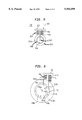
- Control unit 60 preferably includes a digital signal processor 66 for processing the data.
Abstract
Description
Claims (28)
l.sub.1 =(L+vΔt)/2)
l.sub.1 =(L+vΔt)/2)
Priority Applications (1)
| Application Number | Priority Date | Filing Date | Title |
|---|---|---|---|
| US09/006,534 US5954599A (en) | 1998-01-13 | 1998-01-13 | Automated sport boundary officiating system |
Applications Claiming Priority (1)
| Application Number | Priority Date | Filing Date | Title |
|---|---|---|---|
| US09/006,534 US5954599A (en) | 1998-01-13 | 1998-01-13 | Automated sport boundary officiating system |
Publications (1)
| Publication Number | Publication Date |
|---|---|
| US5954599A true US5954599A (en) | 1999-09-21 |
Family
ID=21721345
Family Applications (1)
| Application Number | Title | Priority Date | Filing Date |
|---|---|---|---|
| US09/006,534 Expired - Lifetime US5954599A (en) | 1998-01-13 | 1998-01-13 | Automated sport boundary officiating system |
Country Status (1)
| Country | Link |
|---|---|
| US (1) | US5954599A (en) |
Cited By (33)
| Publication number | Priority date | Publication date | Assignee | Title |
|---|---|---|---|---|
| US20060178235A1 (en) * | 2005-02-05 | 2006-08-10 | Avaya Technology Corp. | Apparatus and method for determining participant contact with a sports object |
| US20060236760A1 (en) * | 2005-04-26 | 2006-10-26 | Belisle William R | Sports activity viewing, sensing, and interpreting system |
| US20060287140A1 (en) * | 2005-06-16 | 2006-12-21 | Brandt Richard A | Automated line calling system |
| US7369038B1 (en) * | 2005-10-28 | 2008-05-06 | Thompson James F | Automated detection system for sports fields and the like |
| WO2008103440A2 (en) | 2007-02-23 | 2008-08-28 | Hawk-Eye Sensors Limited | System and method of preparing a playing surface |
| US20090067670A1 (en) * | 2007-09-07 | 2009-03-12 | Edh Sa (Pty) Ltd. | Methods and processes for detecting a mark on a playing surface and for tracking an object |
| US20090243871A1 (en) * | 2006-09-19 | 2009-10-01 | Kevin Botting | Method and apparatus for preventing hitting in a restricted zone during game play |
| US20100181996A1 (en) * | 2007-03-30 | 2010-07-22 | Walter Englert | Movement range for a mobile object and evaluation apparatus for determining a position of a mobile object |
| US20120038347A1 (en) * | 2007-09-19 | 2012-02-16 | Tilman Bucher | Automatic determination of the position of an object |
| US20150279595A1 (en) * | 2014-03-26 | 2015-10-01 | Mark E Ralstin | Linear impact switch for detecting generally horizontal impacts |
| CN106943734A (en) * | 2017-05-04 | 2017-07-14 | 东北石油大学 | A kind of trainer for being used to judge tennis out-of-bounds training |
| US9744429B1 (en) | 2016-11-03 | 2017-08-29 | Ronald J. Meetin | Information-presentation structure with impact-sensitive color change and restitution matching |
| US9764216B1 (en) | 2016-11-03 | 2017-09-19 | Ronald J. Meetin | Information-presentation structure with impact-sensitive color change to different colors dependent on location in variable-color region of single normal color |
| US9789381B1 (en) * | 2016-11-03 | 2017-10-17 | Ronald J. Meetin | Information-presentation structure with pressure spreading and pressure-sensitive color change |
| US9855485B1 (en) * | 2016-11-03 | 2018-01-02 | Ronald J. Meetin | Information-presentation structure with intelligently controlled impact-sensitive color change |
| US9925415B1 (en) | 2016-11-03 | 2018-03-27 | Ronald J. Meetin | Information-presentation structure with impact-sensitive color change chosen to accommodate color vision deficiency |
| US20180117443A1 (en) * | 2016-11-03 | 2018-05-03 | Ronald J. Meetin | Information-Presentation Structure with Compensation to Increase Size of Color-Changed Print Area |
| US20180120174A1 (en) * | 2016-11-03 | 2018-05-03 | Ronald J. Meetin | Information-Presentation Structure Using Electrode Assembly for Impact-Sensitive Color Change |
| US20180117399A1 (en) * | 2016-11-03 | 2018-05-03 | Ronald J. Meetin | Information-Presentation Structure with Visible Record of Color-Changed Print Area at Impact Location |
| US20180117402A1 (en) * | 2016-11-03 | 2018-05-03 | Ronald J. Meetin | Information-Presentation Structure with Separate Impact-Sensitive and Color-Change Components |
| US10004948B2 (en) | 2016-11-03 | 2018-06-26 | Ronald J. Meetin | Information-presentation structure with impact-sensitive color changing incorporated into tennis court |
| US10010751B2 (en) | 2016-11-03 | 2018-07-03 | Ronald J. Meetin | Information-presentation structure with impact-sensitive color changing incorporated into football or baseball/softball field |
| US10071283B2 (en) | 2016-11-03 | 2018-09-11 | Ronald J. Meetin | Information-presentation structure with impact-sensitive color changing incorporated into sports-playing structure such as basketball or volleyball court |
| US10112101B2 (en) | 2016-11-03 | 2018-10-30 | Ronald J. Meetin | Information-presentation structure with impact-sensitive color change and sound generation |
| US10130844B2 (en) | 2016-11-03 | 2018-11-20 | Ronald J. Meetin | Information-presentation structure with impact-sensitive color change to different colors dependent on impact conditions |
| US10252108B2 (en) | 2016-11-03 | 2019-04-09 | Ronald J. Meetin | Information-presentation structure with impact-sensitive color change dependent on object tracking |
| US10258827B2 (en) | 2016-11-03 | 2019-04-16 | Ronald J. Meetin | Information-presentation structure with impact-sensitive color-change and image generation |
| US10258826B2 (en) | 2016-11-03 | 2019-04-16 | Ronald J. Meetin | Information-presentation structure with post-impact duration-adjustable impact-sensitive color change |
| US10279215B2 (en) | 2016-11-03 | 2019-05-07 | Ronald J. Meetin | Information-presentation structure with impact-sensitive color change of pre-established deformation-controlled extended color-change duration |
| US10300336B2 (en) | 2016-11-03 | 2019-05-28 | Ronald J. Meetin | Information-presentation structure with cell arrangement for impact-sensing color change |
| US10328306B2 (en) | 2016-11-03 | 2019-06-25 | Ronald J. Meetin | Information-presentation structure with impact-sensitive color change and overlying protection or/and surface color control |
| US10357703B2 (en) | 2016-11-03 | 2019-07-23 | Ronald J. Meetin | Information-presentation structure having rapid impact-sensitive color change achieved with separate impact-sensing and color-change components |
| US10363474B2 (en) | 2016-11-03 | 2019-07-30 | Ronald J. Meetin | Information-presentation structure with impact-sensitive color change by light emission |
Citations (17)
| Publication number | Priority date | Publication date | Assignee | Title |
|---|---|---|---|---|
| US3415517A (en) * | 1965-10-18 | 1968-12-10 | Krist Henry Kelvin | Automatic impact indicator system for tennis |
| US3982759A (en) * | 1974-03-25 | 1976-09-28 | Grant Geoffrey F | Tennis court line monitoring apparatus |
| US4092634A (en) * | 1976-10-06 | 1978-05-30 | John J. Schlager | Electric indicator system for ball games |
| US4365805A (en) * | 1980-12-17 | 1982-12-28 | Carl Levine | System for monitoring tennis court boundary lines |
| US4432058A (en) * | 1979-07-17 | 1984-02-14 | Supran Lyle D | Micro-computer network systems for making and using automatic line-call decisions in tennis |
| US4664376A (en) * | 1981-12-03 | 1987-05-12 | Gray George S | Line fault detector |
| US4840377A (en) * | 1987-12-14 | 1989-06-20 | C. Frederick Bowser | Electrical tape boundary sensor apparatus |
| US4855711A (en) * | 1987-06-29 | 1989-08-08 | Sensor Science | Impact detection apparatus |
| US4859986A (en) * | 1987-09-24 | 1989-08-22 | Auken John A Van | Object touchdown and net contact detection systems and game apparatus employing same |
| US4866414A (en) * | 1988-04-04 | 1989-09-12 | Sever Diaconu | Optoelectronic lawn tennis linesman system |
| US5059944A (en) * | 1989-08-02 | 1991-10-22 | Carmona Pedro M | Tennis court boundary sensor |
| US5082263A (en) * | 1990-11-06 | 1992-01-21 | Richard Berger | Method of and system for determining position of tennis ball relative to tennis court, and tennis ball provided therefor |
| US5138322A (en) * | 1991-08-20 | 1992-08-11 | Matrix Engineering, Inc. | Method and apparatus for radar measurement of ball in play |
| US5303915A (en) * | 1990-06-27 | 1994-04-19 | Caldone Pty Limited | Tennis ball to line location |
| US5342042A (en) * | 1987-06-30 | 1994-08-30 | Caldone Pty. Limited | Ball location system |
| US5394824A (en) * | 1992-10-07 | 1995-03-07 | Johnson, Jr.; Lawrence F. | Thermochromic sensor for locating an area of contact |
| US5489886A (en) * | 1992-08-07 | 1996-02-06 | Alos-Officiating Tennis System Limited | Automatic line officiating system and method thereof |
-
1998
- 1998-01-13 US US09/006,534 patent/US5954599A/en not_active Expired - Lifetime
Patent Citations (17)
| Publication number | Priority date | Publication date | Assignee | Title |
|---|---|---|---|---|
| US3415517A (en) * | 1965-10-18 | 1968-12-10 | Krist Henry Kelvin | Automatic impact indicator system for tennis |
| US3982759A (en) * | 1974-03-25 | 1976-09-28 | Grant Geoffrey F | Tennis court line monitoring apparatus |
| US4092634A (en) * | 1976-10-06 | 1978-05-30 | John J. Schlager | Electric indicator system for ball games |
| US4432058A (en) * | 1979-07-17 | 1984-02-14 | Supran Lyle D | Micro-computer network systems for making and using automatic line-call decisions in tennis |
| US4365805A (en) * | 1980-12-17 | 1982-12-28 | Carl Levine | System for monitoring tennis court boundary lines |
| US4664376A (en) * | 1981-12-03 | 1987-05-12 | Gray George S | Line fault detector |
| US4855711A (en) * | 1987-06-29 | 1989-08-08 | Sensor Science | Impact detection apparatus |
| US5342042A (en) * | 1987-06-30 | 1994-08-30 | Caldone Pty. Limited | Ball location system |
| US4859986A (en) * | 1987-09-24 | 1989-08-22 | Auken John A Van | Object touchdown and net contact detection systems and game apparatus employing same |
| US4840377A (en) * | 1987-12-14 | 1989-06-20 | C. Frederick Bowser | Electrical tape boundary sensor apparatus |
| US4866414A (en) * | 1988-04-04 | 1989-09-12 | Sever Diaconu | Optoelectronic lawn tennis linesman system |
| US5059944A (en) * | 1989-08-02 | 1991-10-22 | Carmona Pedro M | Tennis court boundary sensor |
| US5303915A (en) * | 1990-06-27 | 1994-04-19 | Caldone Pty Limited | Tennis ball to line location |
| US5082263A (en) * | 1990-11-06 | 1992-01-21 | Richard Berger | Method of and system for determining position of tennis ball relative to tennis court, and tennis ball provided therefor |
| US5138322A (en) * | 1991-08-20 | 1992-08-11 | Matrix Engineering, Inc. | Method and apparatus for radar measurement of ball in play |
| US5489886A (en) * | 1992-08-07 | 1996-02-06 | Alos-Officiating Tennis System Limited | Automatic line officiating system and method thereof |
| US5394824A (en) * | 1992-10-07 | 1995-03-07 | Johnson, Jr.; Lawrence F. | Thermochromic sensor for locating an area of contact |
Cited By (47)
| Publication number | Priority date | Publication date | Assignee | Title |
|---|---|---|---|---|
| US20060178235A1 (en) * | 2005-02-05 | 2006-08-10 | Avaya Technology Corp. | Apparatus and method for determining participant contact with a sports object |
| US20060236760A1 (en) * | 2005-04-26 | 2006-10-26 | Belisle William R | Sports activity viewing, sensing, and interpreting system |
| US7984544B2 (en) | 2005-06-16 | 2011-07-26 | Ilya D. Rosenberg | Method for manufacturing long force sensors using screen printing technology |
| US20060287140A1 (en) * | 2005-06-16 | 2006-12-21 | Brandt Richard A | Automated line calling system |
| US20090143174A1 (en) * | 2005-06-16 | 2009-06-04 | Brandt Richard A | Automated line calling system |
| US20080314165A1 (en) * | 2005-06-16 | 2008-12-25 | Rosenberg Ilya D | Method for Manufacturing Long Force Sensors Using Screen Printing Technology |
| US7369038B1 (en) * | 2005-10-28 | 2008-05-06 | Thompson James F | Automated detection system for sports fields and the like |
| US20090243871A1 (en) * | 2006-09-19 | 2009-10-01 | Kevin Botting | Method and apparatus for preventing hitting in a restricted zone during game play |
| US8362912B2 (en) * | 2006-09-19 | 2013-01-29 | Kevin Botting | Method and apparatus for preventing hitting in a restricted zone during game play |
| US20080220912A1 (en) * | 2007-02-23 | 2008-09-11 | Hawk-Eye Sensors Limited | System and method of preparing a playing surface |
| WO2008103440A2 (en) | 2007-02-23 | 2008-08-28 | Hawk-Eye Sensors Limited | System and method of preparing a playing surface |
| US7846046B2 (en) | 2007-02-23 | 2010-12-07 | Hawk-Eye Sensors Limited | System and method of preparing a playing surface |
| US20100181996A1 (en) * | 2007-03-30 | 2010-07-22 | Walter Englert | Movement range for a mobile object and evaluation apparatus for determining a position of a mobile object |
| US20090067670A1 (en) * | 2007-09-07 | 2009-03-12 | Edh Sa (Pty) Ltd. | Methods and processes for detecting a mark on a playing surface and for tracking an object |
| US8189857B2 (en) | 2007-09-07 | 2012-05-29 | EDH Holding (Pty) Ltd | Methods and processes for detecting a mark on a playing surface and for tracking an object |
| US20120038347A1 (en) * | 2007-09-19 | 2012-02-16 | Tilman Bucher | Automatic determination of the position of an object |
| US20150279595A1 (en) * | 2014-03-26 | 2015-10-01 | Mark E Ralstin | Linear impact switch for detecting generally horizontal impacts |
| US9925415B1 (en) | 2016-11-03 | 2018-03-27 | Ronald J. Meetin | Information-presentation structure with impact-sensitive color change chosen to accommodate color vision deficiency |
| US10279215B2 (en) | 2016-11-03 | 2019-05-07 | Ronald J. Meetin | Information-presentation structure with impact-sensitive color change of pre-established deformation-controlled extended color-change duration |
| US9764216B1 (en) | 2016-11-03 | 2017-09-19 | Ronald J. Meetin | Information-presentation structure with impact-sensitive color change to different colors dependent on location in variable-color region of single normal color |
| US9789381B1 (en) * | 2016-11-03 | 2017-10-17 | Ronald J. Meetin | Information-presentation structure with pressure spreading and pressure-sensitive color change |
| US9855485B1 (en) * | 2016-11-03 | 2018-01-02 | Ronald J. Meetin | Information-presentation structure with intelligently controlled impact-sensitive color change |
| US11931640B2 (en) | 2016-11-03 | 2024-03-19 | Ronald J. Meetin | Information-presentation structure with visible record of color-changed print area at impact location |
| US20180117443A1 (en) * | 2016-11-03 | 2018-05-03 | Ronald J. Meetin | Information-Presentation Structure with Compensation to Increase Size of Color-Changed Print Area |
| US20180120174A1 (en) * | 2016-11-03 | 2018-05-03 | Ronald J. Meetin | Information-Presentation Structure Using Electrode Assembly for Impact-Sensitive Color Change |
| US20180117399A1 (en) * | 2016-11-03 | 2018-05-03 | Ronald J. Meetin | Information-Presentation Structure with Visible Record of Color-Changed Print Area at Impact Location |
| US20180117402A1 (en) * | 2016-11-03 | 2018-05-03 | Ronald J. Meetin | Information-Presentation Structure with Separate Impact-Sensitive and Color-Change Components |
| US10004948B2 (en) | 2016-11-03 | 2018-06-26 | Ronald J. Meetin | Information-presentation structure with impact-sensitive color changing incorporated into tennis court |
| US10010751B2 (en) | 2016-11-03 | 2018-07-03 | Ronald J. Meetin | Information-presentation structure with impact-sensitive color changing incorporated into football or baseball/softball field |
| US10071283B2 (en) | 2016-11-03 | 2018-09-11 | Ronald J. Meetin | Information-presentation structure with impact-sensitive color changing incorporated into sports-playing structure such as basketball or volleyball court |
| US10112101B2 (en) | 2016-11-03 | 2018-10-30 | Ronald J. Meetin | Information-presentation structure with impact-sensitive color change and sound generation |
| US10130844B2 (en) | 2016-11-03 | 2018-11-20 | Ronald J. Meetin | Information-presentation structure with impact-sensitive color change to different colors dependent on impact conditions |
| US10864427B2 (en) * | 2016-11-03 | 2020-12-15 | Ronald J. Meetin | Information-presentation structure with smoothened impact-sensitive color-changed print area |
| US10252108B2 (en) | 2016-11-03 | 2019-04-09 | Ronald J. Meetin | Information-presentation structure with impact-sensitive color change dependent on object tracking |
| US10258827B2 (en) | 2016-11-03 | 2019-04-16 | Ronald J. Meetin | Information-presentation structure with impact-sensitive color-change and image generation |
| US10258859B2 (en) * | 2016-11-03 | 2019-04-16 | Ronald J. Meetin | Information-presentation structure with visible record of color-changed print area at impact location |
| US10258826B2 (en) | 2016-11-03 | 2019-04-16 | Ronald J. Meetin | Information-presentation structure with post-impact duration-adjustable impact-sensitive color change |
| US10258825B2 (en) * | 2016-11-03 | 2019-04-16 | Ronald J. Meetin | Information-presentation structure with separate impact-sensitive and color-change components |
| US10258860B2 (en) * | 2016-11-03 | 2019-04-16 | Ronald J. Meetin | Information-presentation structure with compensation to increase size of color-changed print area |
| US9744429B1 (en) | 2016-11-03 | 2017-08-29 | Ronald J. Meetin | Information-presentation structure with impact-sensitive color change and restitution matching |
| US10288500B2 (en) * | 2016-11-03 | 2019-05-14 | Ronald J. Meetin | Information-presentation structure using electrode assembly for impact-sensitive color change |
| US10300336B2 (en) | 2016-11-03 | 2019-05-28 | Ronald J. Meetin | Information-presentation structure with cell arrangement for impact-sensing color change |
| US10328306B2 (en) | 2016-11-03 | 2019-06-25 | Ronald J. Meetin | Information-presentation structure with impact-sensitive color change and overlying protection or/and surface color control |
| US10357703B2 (en) | 2016-11-03 | 2019-07-23 | Ronald J. Meetin | Information-presentation structure having rapid impact-sensitive color change achieved with separate impact-sensing and color-change components |
| US10363474B2 (en) | 2016-11-03 | 2019-07-30 | Ronald J. Meetin | Information-presentation structure with impact-sensitive color change by light emission |
| CN106943734B (en) * | 2017-05-04 | 2019-01-01 | 东北石油大学 | A kind of training device trained for judging tennis out-of-bounds |
| CN106943734A (en) * | 2017-05-04 | 2017-07-14 | 东北石油大学 | A kind of trainer for being used to judge tennis out-of-bounds training |
Similar Documents
| Publication | Publication Date | Title |
|---|---|---|
| US5954599A (en) | Automated sport boundary officiating system | |
| US5908361A (en) | Automated tennis line calling system | |
| US4855711A (en) | Impact detection apparatus | |
| US4365805A (en) | System for monitoring tennis court boundary lines | |
| US5672128A (en) | Electronic automated game line | |
| US5926780A (en) | System for measuring the initial velocity vector of a ball and method of use | |
| US5394824A (en) | Thermochromic sensor for locating an area of contact | |
| US3415517A (en) | Automatic impact indicator system for tennis | |
| US3982759A (en) | Tennis court line monitoring apparatus | |
| US6134965A (en) | Device for measuring at least one physical parameter relating to a propelled game ball | |
| EP0184410A2 (en) | Golf simulating apparatus | |
| CA1130333A (en) | Electronic athletic equipment | |
| US4673183A (en) | Golf playing field with ball detecting radar units | |
| US4101132A (en) | Electronic athletic equipment | |
| US4840377A (en) | Electrical tape boundary sensor apparatus | |
| US3992012A (en) | Electrical golf club swing monitor | |
| US20040082414A1 (en) | Device for measuring an impact force applied to an object | |
| US20020107077A1 (en) | Athletic ball impact measurement and display device | |
| US2933681A (en) | Golf practice device | |
| US4422647A (en) | Volleyball out of bounds detecting and indicating system | |
| WO1995034351A1 (en) | Baseball pitcher game and training apparatus | |
| JPS63194679A (en) | Photoelectric-piezoelectric type speed/shock sensor | |
| EP1434629A1 (en) | Sport swing analysis system | |
| EP1725309B1 (en) | Mat for sport and games | |
| JPH03258273A (en) | Training gold device |
Legal Events
| Date | Code | Title | Description |
|---|---|---|---|
| AS | Assignment |
Owner name: LUCENT TECHNOLOGIES, INC., NEW JERSEY Free format text: ASSIGNMENT OF ASSIGNORS INTEREST;ASSIGNOR:LIN, DON L.;REEL/FRAME:008927/0827 Effective date: 19980108 |
|
| STCF | Information on status: patent grant |
Free format text: PATENTED CASE |
|
| FEPP | Fee payment procedure |
Free format text: PAYOR NUMBER ASSIGNED (ORIGINAL EVENT CODE: ASPN); ENTITY STATUS OF PATENT OWNER: LARGE ENTITY |
|
| AS | Assignment |
Owner name: THE CHASE MANHATTAN BANK, AS COLLATERAL AGENT, TEX Free format text: CONDITIONAL ASSIGNMENT OF AND SECURITY INTEREST IN PATENT RIGHTS;ASSIGNOR:LUCENT TECHNOLOGIES INC. (DE CORPORATION);REEL/FRAME:011722/0048 Effective date: 20010222 |
|
| FPAY | Fee payment |
Year of fee payment: 4 |
|
| AS | Assignment |
Owner name: LUCENT TECHNOLOGIES INC., NEW JERSEY Free format text: TERMINATION AND RELEASE OF SECURITY INTEREST IN PATENT RIGHTS;ASSIGNOR:JPMORGAN CHASE BANK, N.A. (FORMERLY KNOWN AS THE CHASE MANHATTAN BANK), AS ADMINISTRATIVE AGENT;REEL/FRAME:018590/0047 Effective date: 20061130 |
|
| FPAY | Fee payment |
Year of fee payment: 8 |
|
| FPAY | Fee payment |
Year of fee payment: 12 |
|
| AS | Assignment |
Owner name: OMEGA CREDIT OPPORTUNITIES MASTER FUND, LP, NEW YORK Free format text: SECURITY INTEREST;ASSIGNOR:WSOU INVESTMENTS, LLC;REEL/FRAME:043966/0574 Effective date: 20170822 Owner name: OMEGA CREDIT OPPORTUNITIES MASTER FUND, LP, NEW YO Free format text: SECURITY INTEREST;ASSIGNOR:WSOU INVESTMENTS, LLC;REEL/FRAME:043966/0574 Effective date: 20170822 |
|
| AS | Assignment |
Owner name: WSOU INVESTMENTS, LLC, CALIFORNIA Free format text: ASSIGNMENT OF ASSIGNORS INTEREST;ASSIGNOR:ALCATEL LUCENT;REEL/FRAME:044000/0053 Effective date: 20170722 |
|
| AS | Assignment |
Owner name: WSOU INVESTMENTS, LLC, CALIFORNIA Free format text: RELEASE BY SECURED PARTY;ASSIGNOR:OCO OPPORTUNITIES MASTER FUND, L.P. (F/K/A OMEGA CREDIT OPPORTUNITIES MASTER FUND LP;REEL/FRAME:049246/0405 Effective date: 20190516 |
|
| AS | Assignment |
Owner name: OT WSOU TERRIER HOLDINGS, LLC, CALIFORNIA Free format text: SECURITY INTEREST;ASSIGNOR:WSOU INVESTMENTS, LLC;REEL/FRAME:056990/0081 Effective date: 20210528 |