US5982917A - Computer-assisted method and apparatus for displaying x-ray images - Google Patents
Computer-assisted method and apparatus for displaying x-ray images Download PDFInfo
- Publication number
- US5982917A US5982917A US09/138,492 US13849298A US5982917A US 5982917 A US5982917 A US 5982917A US 13849298 A US13849298 A US 13849298A US 5982917 A US5982917 A US 5982917A
- Authority
- US
- United States
- Prior art keywords
- image
- mass
- digital
- detection
- directional
- Prior art date
- Legal status (The legal status is an assumption and is not a legal conclusion. Google has not performed a legal analysis and makes no representation as to the accuracy of the status listed.)
- Expired - Lifetime
Links
Images


Classifications
-
- G—PHYSICS
- G06—COMPUTING; CALCULATING OR COUNTING
- G06T—IMAGE DATA PROCESSING OR GENERATION, IN GENERAL
- G06T7/00—Image analysis
- G06T7/0002—Inspection of images, e.g. flaw detection
- G06T7/0012—Biomedical image inspection
-
- Y—GENERAL TAGGING OF NEW TECHNOLOGICAL DEVELOPMENTS; GENERAL TAGGING OF CROSS-SECTIONAL TECHNOLOGIES SPANNING OVER SEVERAL SECTIONS OF THE IPC; TECHNICAL SUBJECTS COVERED BY FORMER USPC CROSS-REFERENCE ART COLLECTIONS [XRACs] AND DIGESTS
- Y10—TECHNICAL SUBJECTS COVERED BY FORMER USPC
- Y10S—TECHNICAL SUBJECTS COVERED BY FORMER USPC CROSS-REFERENCE ART COLLECTIONS [XRACs] AND DIGESTS
- Y10S128/00—Surgery
- Y10S128/92—Computer assisted medical diagnostics
- Y10S128/922—Computer assisted medical diagnostics including image analysis
Definitions
- the invention relates to the development of computer-assisted diagnostic (CAD) methods for the analysis of digital X-ray images or gray-scale images generated by other digital sensors. More particularly, the invention relates to the use of CAD methods for the analysis of mammography images.
- CAD computer-assisted diagnostic
- CAD computer-assisted diagnostic
- Mass Detection Methods Numerous investigators have addressed mass detection and classification. The methods reported in the literature for mass detection can be grouped into two categories. In the first category, the methods involve the use of asymmetry measures of the left and right breast. The detection of masses is based on deviations from the architectural symmetry of normal right and left breasts, with asymmetry indicating suspicious areas. The basic approach of the methods in this category is to search for brightness or texture differences between corresponding locations on left and right images (Winsberg et al., 1967; Hand et al., 1979; Semmlow et al., 1980; Kimme et al., 1975; Hoyuer et al., 1978/79; Lau et al., 1991).
- Miller and Astley (193) proposed an automatic method for detecting asymmetry based on the comparison of corresponding anatomic structures identified by the shape and brightness distribution of these regions.
- the detection performance of these methods depends strongly on two factors, the alignment of left and right breast images and the individual feature analysis of breast images. Due to the fact that the size and shape of the two breasts may be different, it may be difficult to identify accurately corresponding locations.
- the asymmetry cues generated may not be sufficiently specific to be used as prompts for small and subtle abnormalities in CAD systems.
- Individual image feature analysis is the basis of alignment and the comparison of symmetry, and is closely related to the second class of mass detection methods.
- the second class of CAD methods focus on the determination of features that allow the differentiation of masses from normal parenchymal tissues in a given image. They consist of two major steps: feature extraction and discrimination.
- the features include textures derived from a gray-level dependence matrix (Miller and Astley, 1993; Chan et al., 1995), texture energy obtained from the output of Law's filters (Gupta et al., 1995), density and morphological features (Lai et al., 1989; Brzakovic et al., 1990). Recently, Chan et al. (Petrick et al., 1995) investigated the advantage of combining the morphological and texture features for mass detection.
- Wavelet-based methods have been proposed for image enhancement in digital mammography.
- Laine et al. (1994) used wavelet maxima coefficients for image enhancement and multiscale edge representation, the work being a modification of the dyadic wavelet transform originally proposed by Mallat (1992).
- Various approaches were used for image enhancement, including the use of linear, exponential, and constant weight functions for modification of the coefficients of the original dyadic wavelet transform.
- preprocessing for noise removal was not used, and so multiscale edges are mixed with structured noise in digital mammograms.
- a modification of the coefficients of the dyadic wavelet transform may result in less than optimal reconstruction.
- the wavelet transforms are not implemented on filter banks such as quadrature mirror filters. Emphasis is placed on the use of the dyadic wavelet transform for image enhancement for improved visual diagnosis.
- the methods include: (a) analysis of the orientation of edges through the image to identify areas of locally radiating structure, with false positive reduction using Law's texture analysis (Kegelmeyer, 1992; Kegelmeyer et al., 1994; (b) use of radial line enhancement followed by Bayesian combination of caes generated by the Hough transform (Astley, et al., 1993); (c) use of gray-scale seed-growing methods to allow analysis of radial gradient histograms surrounding the mass of interest (Giaer et al., 1994a), and finally (d) detection of stellate patterns without assuming the presence of a central mass for the detection of subtle cancers with line orientation obtained by three second order Gaussiar derivative operators (Karssemeijer, 1994).
- Claridge and Richter investigated methods of improving the diagnosis of mammographic lesions by using computer image analysis methods for characterization of lesion edge definition and accurate localization of the lesion boundary.
- Classification methods proposed to differentiate masses from normal tissue have included the use of decision trees (Li et al., 1995; Kegelmeyer et al., 1994), Bayes classifiers (Brzakovic et al., 1990), linear discriminant analysis (Chan et al., 1995), linear and quadratic classifiers (Woods et al., 1994), and neural networks (NN) (Petrick et al., 1995; Wu et al., 1993).
- the methods known in the art generally use sensitivity of detection and false positive detection rate as means for evaluating CAD algorithms (Lai et al., 1989; Brzakovic et al., 1990) and have met with varying levels of success for the databases containing only circumscribed, speculated, or all types of masses. Since the image databases vary, a direct comparison cannot be made.
- Mass Classification (Benign versus Malignant).
- Features proposed for mass classification specifically using visual criteria have been reported (Wu et al., 1993) that closely correlate with the American College of Radiology (ACR) Lexicon visual criteria. They include density-related features, shape and size features, mass margins, spiculations, and correlation with other clinical data, including the patient's age.
- the computation of image-related features has been proposed (Kilday et al., 1993) with an emphasis on gross and fine shape-related features that include three radial length measures, tumor boundary roughness, and area parameters.
- the use of mass-intensity-related features using fractional dimension analysis and nonlinear filters has been proposed for quantifying the degree of lesion perfusion to identify malignant lesions with rough intensity surfaces (Burdett et al., 1993).
- spiculation analysis has been greatly emphasized.
- Known methods include: (a) use of a line-enhancement operator to measure linearity, length, and width parameters (Parr et al., 1994), (b) second-order Gaussian derivatives to measure line orientation to determine the total number of pixels pointing in the direction of the center of the mass, with a binomial statistical analysis of the angular distributions of the spiculations (Karssemeijer, 1994).
- Claridge et al. (1994) used a similar spiculation index to reflect the relative magnitude of horizontal/vertical directions.
- Huo et al. (1995) have reported a comprehensive approach using both radial edge gradient analysis and cumulative edge gradient distribution, determined by seed growing, within manually defined regions of interest.
- the classificaticon methods employed are similar to those used for mass detection, with an emphasis on the use of back-propagation NNs (Huo et al., 1995; Wu et al., 1993), where variations in She output node of the NN can be employed to generate computer or simulated receiver operating characteristic (ROC) curves as a means for evaluation of the CAD method or modification to CAD modules (Huo et al., 1995; Lo et al., 1995).
- ROC receiver operating characteristic
- the accuracy of a detection or classification algorithm can be characterized entirely by an ROC curve (Metz, 1986, 1989) or a free-response ROC (FROC) curve (Chakraborty, 1989).
- a modular CAD method and apparatus that comprises image preprocessing to allow improved feature extraction in the gray-level, directional texture, and morphological (shape) domains.
- This method and apparatus achieve improved sensitivity and specificity in mass detection in mammography images.
- the invention can be used, for example, as a "second opinion” strategy or "prereader strategy” at either a centralized location or remote locations using teleradiology/telemedicine strategies, although these uses are not intended to be limiting.
- the objectives are: (a) to use image enhancement and segmentation methods to improve visual interpretation on a computer monitor and thus at least partly to compensate for monitor performance versus conventional light box/film image interpretation; and (b) to use CAD methods for detection and classification to locate suspicious regions and provide a mathematical probability of whether they are benign or malignant.
- the method and apparatus of the present invention are applicable to images such as masses present in a digital mammogram. It is believed that the combined approach of visual and computer aids should thus reduce the inter- and intraobserver variation in image interpretation at, for example, centralized or remote locations and/or when using networked medical computer workstations.
- the invention in terms of computer software design, relates to the use of image preprocessing CAD modules that allow features to be extracted more effectively in the gray-level, directional texture, and morphological domains, to improve detection and classification of suspicious areas such as masses in digital mammography.
- the methods for feature extraction allow feature selection and pattern recognition methods to be more effectively implemented.
- the invention includes a plurality of modules:
- a filter which may comprise a multistage nonlinear tree structured filter (TSF) or an adaptive multistage nonlinear filter (AMNF), for image noise suppression and improved feature extraction in the gray-level domain;
- TSF multistage nonlinear tree structured filter
- AMNF adaptive multistage nonlinear filter
- An N-directional wavelet transform for decomposing the filtered image to obtain high (N) orientation selectivity in the directional texture domain
- An image smoothing algorithm to remove directional features from the decomposed image and a transform, such as an M-channel tree structured wavelet transform (TSWT), for enhancing suspicious areas cascaded with an algorithm, such as an adaptive clustering algorithm for segmenting suspicious areas for all mass types to allow features to be computed in the morpholoichal (shape) domain;
- TSWT tree structured wavelet transform
- a directional feature analysis and enhancement module for differentiating directional features within the digital mammogram from potential spiculations associated with spiculated masses and for computing features in the directional texture domain;
- a mass detection module for classifying suspicious areas as masses or normal tissue, such as by pattern recognition methods.
- a mass classification module for classifying masses as benign or malignant, such as by pattern recognition methods.
- the apparatus typically includes a medical image workstation using high-resolution monitors to display raw, enhanced, and segmented images to permit better visual interpretation.
- this method and apparatus are the use of multiresolution/multiorientation wavelet transforms in the image preprocessing for improved feature extraction in the three recited domains (gray-level, morphological, and directional texture) and the use of higher-order transforms (M,N) and adaptive image processing methods to potentially accommodate the gray-scale and response characteristics of different sensors.
- FIG. 1 is a block diagram of the CAD modules leading from a digital image to a display of the enhanced and raw images.
- FIG. 2 is a diagram of multiorientation wavelet transform (MWT) decomposition in the Fourier domain of support of ⁇ ( ⁇ x , ⁇ y ) into 8 wavelets ⁇ i ( ⁇ x , ⁇ y ), 1 ⁇ i ⁇ 8, having different orientation selectivities, wherein the supports of the functions ⁇ i ( ⁇ x , ⁇ y ) are symmetrical about 0 and are rotated from one another.
- MTT multiorientation wavelet transform
- FIG. 3 is a diagram of a multiresolution wavelet decomposition to illustrate that the conventional wavelet transform does not have a directional constraint.
- DWT directional wavelet transform
- FIG. 6 is a block diagram showing image feature decomposition, using the DWT and an adaptive combiner.
- FIG. 7 illustrates the output of some of the modules of the present invention for segmentation of suspicious areas and spiculation extraction: (a) representative raw digitized mammogram for a spiculated mass; (b) directional features computed by the DWT (CAD module 2); (c) enhanced mammogram obtained by adding directional features to the noise-suppressed image (CPD module 4); (d) smoothed image by subtraction of directional features from the noise-suppressed image; (e) segmented image showing the suspicious areas using CAD module 3; if) final detected mass with spiculations and false positives using CAD modules 1-5.
- CAD module 2 directional features computed by the DWT
- CPD module 4 enhanced mammogram obtained by adding directional features to the noise-suppressed image
- CPD module 4 smoothed image by subtraction of directional features from the noise-suppressed image
- segmented image showing the suspicious areas using CAD module 3; if) final detected mass with spiculations and false positives
- FIG. 8 illustrates the output of some of the CAD modules for a circumscribed lesion: (a) representative raw digitized mammogram; (b) directional features computed by the DWT (CAD module 2); (c) enhanced mammogram obtained by adding direction features to the noise-suppressed image (CAD module 4); (d) smoothed image obtained by subtraction of directional features from the noise-suppressed image; (e) segmented image showing the suspicious areas using CAD module 3; (f) final detected mass without the presence of speculations and false positives using modules 1-5.
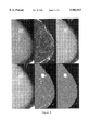
- FIG. 9 illustrates representative results for three cases with spiculated masses with varying size and image contrast: (a-c) subimages of the raw image data; (d-f) masses segmented with spiculations.
- FIG. 10 is a front perspective view of an exemplary medical workstation showing an array of monitors to allow visual inspection of the raw, enhanced, and segmented images of the left and right breast.
- An insert in the segmented image provides the classification probability (benign or malignant).
- the apparatus comprises, and the method comprises the use of, a plurality of CAD modules applied to a raw digital x-ray image for the determination of a suspicious mass and the classification thereof.
- the enhanced images comprise a plurality of enhanced images having experienced a plurality of processing steps. The enhanced images are then displayed with the raw image, a visual comparison permitting an improved interpretation of a detected mass.
- the digital x-ray image is preferably first filtered by either a multistage tree structured nonlinear filter (TSF) with fixed parameters or an adaptive multistage nonlinear filter (AMNF) to suppress image noise while preserving image details potentially to improve feature extraction in the gray-level domain.
- TSF tree structured nonlinear filter
- AMNF adaptive multistage nonlinear filter
- noise-suppression filters are proposed, although these are not meant to be limiting: (a) a tree-structured nonlinear filter (TSF) with fixed parameters for a given digital sensor that is computationally efficient; and (b) an adaptive multistage nonlinear filter (AMNF), which is more suitable for universal application to different sensors with varying noise characteristics. Both filters are applied on a pixel-by-pixel basis throughout the full mammographic image. Both filters can be incorporated into the modular CAD structure shown in FIG. 1.
- TSF Tree-structured filter
- the TSF is a three-stage filter designed with central weighted median filters (CWMFs) as subfiltering blocks (see FIG. 1 in Qian et al., 1994a).
- CWMFs central weighted median filters
- Modified windows of the filter bank in the first stage and comparison of the filtered image to the raw image for each stage are used to preserve image detail, such as parenchymal tissue structures, with significantly improved noise reduction compared with conventional single-stage filters such as the median filter.
- the AMNF is a two-stage filter that incorporates an adaptive operation.
- the first stage contains, by way of example, five different conventional filters with varying filter window sizes, namely, a linear filter (9 ⁇ 9 window), ⁇ trimmed mean (7 ⁇ 7 window), ⁇ trimmed mean (5 ⁇ 5 window), ⁇ trimmed mean (3 ⁇ 3 window), and median filter (3 ⁇ 2 window) [Qian et al., 1995b, FIG. 2, Eq. (6-15)].
- the second stage uses a signal-dependent weighting factor, based on the local signal activity, and its variance are used to select the appropriate filter in the first stage.
- a smoothing filter with a large window is chosen to suppress noise.
- regions of varying signal intensity such as parenchymal tissue structures or suspicious areas (masses)
- a filter with a wider window may be chosen better to preserve image details turing noise suppression.
- the first stage of the filter may also include other filters, such as the previously described TSF further to preserve image details of suspicious areas and adaptively selected, as previously described.
- This AMNF filter design has been described in Qian et al. (1995a,b), the contents of which are incorporated herein by reference.
- the filtered image comprises an image in the gray-level domain. This filtered image is fed into CAD module 2 for decomposition.
- Mallat (1989a) discussed the relationship between multichannel frequency decomposition and the application of wavelet models. This work includes the conceptual basis for a multiorientation wavelet transform (MWT) but did not provide the wavelet function.
- MTT multiorientation wavelet transform
- Grossman and Morlet (1984) have proposed a wavelet function that can be modified to generate the multiorientation wavelet transform conceptually suggested by Mallat (1989a), with an appropriate choice of parameters.
- this MWT is only an approximate solution for the proposed application because of limited directional sensitivity.
- the wavelet function used being commonly referred to as the Morlet wavelet function.
- DWT directional wavelet transform
- the DWT has been designed to allow the directional features to be extracted for improved segmentation of suspicious areas. This includes the removal of speculations in the case of spiculated masses for segementation purposes and the use of ray-tracing methods to differentiate spiculations from other directional features such as ducts. The speculations can then be added to the detected mass.
- the DWT can also be used for image enhancement by simply summing the DWT-enhanced image and the raw image.
- the wavelet transform within orientation i is called a directional wavelet transform, and is defined by
- F( ⁇ x , ⁇ y ) and ⁇ i ( ⁇ x , ⁇ y ) are the Fourier transforms of f(s,y) and ⁇ i (x,y), respectively.
- the MWT within orientation i can be formulated in the Fourier domain with polar coordinate as follows:
- the operation above can be considered to be a multiresolution directional filtering.
- Directional wavelet transform DWT
- the limitations of the directionality for the MWT is indicated in FIG. 4, where the bandwidths for each direction are not well defined.
- a modification to the Morlet wavelet function is used to obtain the directional wavelet function, which is described mathematically as follows: ##EQU6## where ⁇ x ', ⁇ y ' are the rotation coordinates of ⁇ x and ⁇ y ,
- ⁇ is the direction of the wavelet function; the parameters ⁇ and ⁇ 2 are related to the bandwidth of the orientation; ⁇ 1 is the lower cutoff frequency of the directional wavelet function.
- the angle ⁇ i ⁇ /N, where N may be equal to 4, 8, 16, . . , or example.
- a set of spectral images of eight wavelet functions with different directions (i ⁇ /8), 0 ⁇ i ⁇ 7 (i.e., N 8), are shown for the proposed DWT, where the narrower bandwidth and improved directionality can be seen compared with the Morlet DWT.
- three output images are obtained from the feature decomposition by directional wavelet analysis, namely, a directional feature image to allow feature extraction, a directional-feature-enhanced image created by adding directional features to the noise-suppressed image, and finally, a smoothed image obtained by subtraction of directional features from the noise-suppressed image as shown in FIGS. 7 and 8, subparts (b), (c), and (d), respectively.
- ⁇ i (*) refers to the output of a wavelet transform at direction i and resolution j
- W i and W j i are the weights for the adaptive combiners (see FIG. 6).
- the enhanced-image version of the original noise-suppressed image is expressed as:
- Image segmentation is an image decomposition in which the image is decomposed into spatially separated components (Jain, 1989). The pixels in each component have certain similarity in their features, e.g., gray level.
- Two major techniques for image segmentation are the boundary-based approach and the region-based approach. In the boundary-based approach, boundary information is determined based on edge detection. The main idea in region-based segmentation is to identify various regions in an image that have similar features.
- the boundary of a mass is frequently difficult to determine by edge detect on because of the low contrast of the images and the ill-defined edges for many malignant masses.
- the region-based segmentation method is more suitable for segmentation because the pixels within a suspicious area will generally have more uniform intensity and are often brighter than the surrounding tissue.
- the suspicious areas are imbedded in a nonuniform background signal due to surrounding tissue and fat of varying thickness, giving varying X-ray attenuation.
- some form of selective image enhancement of the suspicious areas relative to the background is required prior to segmentation.
- the Daubechies 16-wavelet transform is used, where image decomposition into subimages using an M-channel tree-structured wavelet transform is implemented on quadrature mirror filter banks (QMFs), by way of example (Qian et al., 1993, 1995a).
- QMFs quadrature mirror filter banks
- M 2 M transform
- M 2 channel tree-structured wavelet transform
- AMNF adaptive multistage nonlinear filter
- implementation on different filter banks including QMFs has been described (Qian et al., 1994b, 1995a,b).
- M-channel TSWT is utilized for selective enhancement of suspicious areas, implemented on QMFs (Qian et al., 1994b).
- Selective reconstruction of the M 2 subimages is proposed for image enhancement of suspicious areas.
- Higher-order M channels are used to provide improved image enhancement relative to the background signal, as may be required for the varying gray-scale characteristics of different digital sensors, that is, by more selective reconstruction of the higher-order M 2 subimages.
- Such selective reconstruction of the subimages is currently obtained by visual criteria and the use or a training data set with known ground truth (masses of varying types), that is, selection of images where parenchymal tissue structure is observed to be similar to that of the masses and the removal of subimages that contain background information.
- Adaptive clustering is a generalization of a conventional clustering method such as a K-means method. It is made to adapt to changes in characteristics from pixel to pixel in the same image and changes in statistical properties from image to image.
- the clustering criteria of the AC algorithm consist of two elements: the distance (measured by mean-square error) of the pixel intensity to the cluster centroid and the neighbor constraint, which is based on the Gibbs density distribution. Because the clustering centroid is calculated based on a sliding window instead of the whole image, such as that in the K-means algorithm, it is made adaptive to local characteristics. Also, because a different constraint coefficient is taken based on the standard variance of the image, it is made adaptive to different images.
- Adaptive clustering is an iterative procedure beginning with an initial segmentation. With the iteration of the algorithm the segmentation obtained by adaptive clustering is statistically an approximation of the maximum posterior estimation (Pappas et al., 1992).
- CAD module 3 involves three steps: A simple adaptive thresholding method (Kohler, 1981) is used to segment the full mammogram image into breast tissue and background area (exposed region of film beyond breast boundary). The M-channel TSWT method for image enhancement is applied using the smoothed image (output of CaD module 2). Adaptive clustering, applied to the enhanced image, is used automatically segment the image into suspicious regions, which becomes the input to CAD modules 5 and 6. The overall objective is to preserve image details of the segmented regions to improve shape-related features similar to the ACR BIRADS (American College of Radiology, 1993) for all mass types.
- ACR BIRADS American College of Radiology, 1993
- a tracing algorithm was designed to extract the spicules and differentiate speculations from other directional features. This algorithm consists of two subtracing procedures: contour tracing of an extracted region and spicule tracing. These procedures were applied to the segmented suspicious areas output by CAD module 3 and the directional feature images obtained from the feature decomposition performed by CAD module 2.
- the extracted spiculations are then added to the segmented mass, which permits an improved visual diagnosis of the extent and/or presence of cancer within the breast.
- no spiculations are generally found.
- the directional features are first removed for the purpose of segmentation and then added back in order to visually evaluate the segmented mass. The method, therefore, can be applied to images irrespective of mass type.
- the ray-tracing algorithm proceeds as follows:
- Contour tracing loop (image from CAD module 3):
- Step 1 Locate the initial edge point of the extracted region.
- Step 2 Determine the maximum feature direction, maximum feature intensity, and average feature intensity of eight directional features
- Step 3 If:
- the feature intensity is greater than a threshold I 1 ;
- Step 4 Mark the edge point and search for the next neighborhood edge point
- Step 5 If all pixels on the contour have been visited, stop. Otherwise, go to Step 2.
- Step 0 Initialization (only for the first step in search of each spicule) to determine the search direction for a spicule based on (a) the maximum feature direction of present pixel, (b) the position of the region center relative to the initial point;
- Step 1 Choose the pixels in the neighborhood of the present pixel as a candidate for spicule pixels if (a) they are located in the search direction relative to the present pixel, and (b) their maximum feature directions are within [i-1,i+1], where i is the maximum direction of the present spicule pixel.
- Step 2 If the direction feature intensity of the candidate pixel is (a) the maximum among the candidate pixels, and (b) greater than the threshold i 1 , then it is marked as the next pixel on the spicule line, and go to step 1; otherwise, go to step 3.
- Step 3 Stop and return to the contour tracing loop.
- the ray-tracing algorithm provides a direct measure of the number of spiculations, their length, and distribution and is thus an improved method for analyzing spiculations on spiculated masses. It is our belief that the above method can be readily extended to measure the thickness or morphology of the spiculations in addition to their length using, for example, a modified gray-scale seed-growing method.
- CAD modules 5 and 6 perform the detection and classification of masses. They are described here to demonstrate, by way or example, how the image-processing CAD modules 1-4 in FIG. 1 allow an improvement in how features are computed in the gray-level, morphological, and directional texture domains. Representative features will be identified below. Feature-selection methods to obtain the optimum number of features are not described, as they are not impacted by the preprocessing CAD modules. These methods are described in published textbooks (DeVijver et al., 1982) and may include successive elimination or sequential backward selection methods (Chan et al., 1995; Lo et al., 1995). The proposed subgroups of features are listed in accordance with the American College of Radiology (ACR) Lexicon criteria (mass shape, margins, and density-related features, and can be applied for mass detection, classification, or both.
- ACR American College of Radiology
- Shape Analysis Shapes listed in the ACR Mammography Lexicon include those that can be defined as round, oval, lobulated, or irregular, and such shape features may be helpful in mass detection and classification (Wu et al., 1993). Shape models can be applied to the segmented suspicious areas (CAD module 3) as follows:
- Ratio of semiaxes The ratio of the semiaxes of the above optimized model can be used as a feature parameter, as an indicator of roundness of the mass (Brazakovic et al., 1990, Eq. 11, 12).
- Tumor boundary Iregularity factor A more detailed measure of mass boundary to listinguish cases of microlobulated or indistinct margins is possible; this may be useful for detection but particularly for classification.
- the irregularity metric is the variation in radial length at different boundary points, as proposed by Kilday et al. (1993, Eq. 5).
- Fractal dimension actor The fractal dimension is used as a measure of the roughness of the mass intensity surface proposed for mass detection (Burdett et al., 1993). In all instances, we believe that segmentation of the suspicious areas, with improved image detail, improves the usefulness of the shape-related features for mass detection and classification.
- Mass Margin Analysis may be applied both to spiculations and to the central mass.
- the fuzziness of central mass margins can be used for classifying a probability of malignancy (Parr et al., 1994).
- Features that can be used include:
- Average speculation length This feature is computed by summing the lengths of all detected spiculations (i.e., those consisting of pixels exceeding a given intensity threshold), normalized to the area of the mass.
- Mass Density Analysis is also an important feature for both detection and classification (Giger et al., 1994b; Wu et al., 1993), and these features can be computed from the outputs of CAD modules 1 and 3 in FIG. 1.
- Density uniformity This is a measure of the smoothness of the pixel intensity within the mass boundary (Giger et al., 1994b).
- Relative density The relative average density of the mass (Mt) relative to a region of interest in the surrounding tissue (Ms) is also important for detection and classification (Giger et al., 1994b; Wu et al., 1993), and is determined as the difference in density normaltzed to Ms: (Mt-Ms)/Ms. We believe that an improved delineation of the suspicious area's boundaries improves the computation of mass density and relative density features.
- Mass Detection CAD Modules 5 5. We have used the fuzzy binary decision tree (FBDT) for mass detection (Li et al., 1995, submitted) in the disclosed method. The FBDT was discovered by an empirical selection of features using physician knowledge, where the tests in each of the nodes of the decision tree can be related to thresholds of the measurements (Li et al., 1995).
- FBDT fuzzy binary decision tree
- NN backpropagation neural network
- KF backpropagation training
- the use of a three-layer BPNN is suitable for this work, with a similar structure to that proposed by Clarke et al. (1994).
- the input node number of the proposed BPNN depends on the feature selection, while the hidden node number is optimized with training data set.
- the output of the outcut node corresponds to the detection of mass.
- the generalization capabilities of the neural network can be evaluated using the leave-one-out method on a training database as well as the application to a test database. To do the evaluation, computed ROC curves can be generated by varying the threshold of the output node of the NN (Lo et al., 1995).
- Mass Classification CAD Modules 6 The classification of a mass as benign or malignant from image data is a more difficult task compared with a visual rating by an expert radiologist of the degree of malignancy (Wu et al., 1993). It is believed that the direct detection of spiculations and their associated characteristics will greatly improve classification accuracy, as suggested by other investigators (Kegelmeyer et al., 1994; Huo et al., 1995). No particular distinction will be made between benign and malignant spiculated lesions, as this topic is beyond the scope of the proposed invention and is statistically not very significant. Patient age and other factors may be included as inputs to the classification methods.
- a probabilistic neural network (PNN) is proposed by way of example (Specht, 1990).
- the PNN has a similar structure as BPNN. It is also a multistage feed-forward network.
- the PNN consists of four layers: input units, pattern units, summation units, and output units.
- the PNN is based on Bayes estimation theory and the Parzen PDF estimation method (Parzen, 1962).
- the output of the summation unit corresponds to a probability density, where weights may be systematically changed to generate computed ROC curves similar to the BPNN by changing the threshold.
- the weights of the PNN are computed in a single pass rather than with an iterative search for convergence and is therefore computationally efficient and suitable for both feature selection and the traditional jackknife method for error analysis relating to the training image database.
- the shame of the decision surface can be made as complex as necessary by adjusting parameters, while maintaining sample error tolerance as required for the different problem of mass classification.
- the proposed medical workstation 10 includes the use of three pairs 101,102; 103,104; and 105,106 of high-resolution, high-luminance computer monitors suitable for gray-scale interpretation of digital mammograms, as shown in FIG. 10.
- the medical workstation 10 includes fast disc storage arrays 12 and the necessary hardware 14 to display images of the order of 5 Mbytes or better, as required for digital mammography. Also illustrated is a tape backup unit 16.
- the proposed method and apparatus would employ software for fully operator-independent review of the images; that is, each CAD module requires no operator input for the analysis of mammograms by a physician.
- Directional Wavelet Transform Modules 2.
- the directional wavelet transform is equivalent to a directional high-pass filtering.
- the parameter ⁇ 1 is chosen to be 2, with which the 3-dB orientational bandwidth of the wavelet function is approximately ⁇ /8.
- the choice of the parameter ⁇ 2 depends on the characteristics of directional texture features in the mammogram. It is chosen here in such a way that the spiculated features can be extracted effectively, and was determined empirically.
- the adaptive combiner used is a maximum value selector.
- the wavelet transform was implemented by a pair of quadrature mirror filters (QMF).
- the filter coefficients used here are 16-tap Daubechies wavelet coefficients (Daubechies, 1990).
- Adaptive clustering was the used to segment the suspicious areas.
- the fuzzy binary decision tree was used to classify mass and normal tissue structures. Representative results are shown in FIGS. 7 and 8 for a spiculated mass and a circumscribed mass. For the spiculated mass, the detected mass is segmented with the spiculations for better visual interpretation, that is, allowing the false positives to be readily recognized visually. The results are shown for the circumscribed mass to demonstrate that the apparatus can be used for all mass types.
- FIG. 9 there are shown three stellate masses and their spiculations extracted and added to the mass boundary.
- the morphological and gray-level features are computed based on the mammograms with directional features removed.
- the abnormal mammograms contained at least one tumor of varying size and location. In toto there are 20 stellate, 13 circumscribed, and 15 irregular masses included in the image data set. These mammograms were obtained from a screen/film system, and the films were digitized by a DuPont FD-2000 digitizer (MINDAX Corporation). The image resolution was 220 ⁇ m and 8 bits (256 gray levels) per pixel within the optical density of 0-3.5. A reference image or truth file was formed for each abnormal mammogram, where the tumor was labeled by an expert mammographer based on visual criteria using screen/film and biopsy results.
- the results using the detection algorithm in this case the fuzzy binary decision tree, is reported by way of example. It was first trained with a separate image database containing twenty mammograms selected from the previous image data set to obtain the parameters for feature extraction and classification. Five mammograms with a circumscribed mass, seven with a stellate mass, five with an irregular mass, and three with no mass (i.e., normal) were included. The sensitivity of detection is defined as the ratio of the number of suspicious areas being correctly extracted from the images to the total number of suspicious areas.
- the experimental results demonstrate that the proposed method is very effective.
- the sensitivity of detection for the method was high at 98%, while maintaining a low false positive (FP) detection rate of 1.4 FPs per image.
- the only mass that was missed was a very large circumscribed mass (area greater than 140 ⁇ 140 pixels), which was very different from the selected masses in the training data set.
- the method performed particularly well for masses with spiculated lesions or for those masses that were highly connected to surrounding parenchymal tissues.
- Brzakovic D., S. M. Luo, and P. Brzakovic, "An approach to automated detection of tumors in mammograms," IEEE Trans. Medical Imaging 9, 233-41, 1990.
Abstract
A computer-assisted diagnostic (CAD) method and apparatus are described for the enhancement and detection of suspicious regions in digital X-ray images, with particular emphasis on early cancer detection using digital mammography. An objective is to improve the sensitivity of detection of suspicious areas such as masses, while maintaining a low false positive detection rate, and to classify masses as benign or malignant. A modular CAD technique has been developed as a potentially automatic and/or second-opinion method for mass detection and classification in digital mammography that may in turn be readily modified for application with different digital X-ray detectors with varying gray-scale and resolution characteristics. The method consists of using a plurality of CAD modules to preprocess and enhance image features in the gray-level, the directional texture, and the morphological domains.
Description
This application is a divisional of application Ser. No. 08/659,061 filed Jun. 3, 1996 and issuing as U.S. Pat. No. 5,799,100, commonly owned and assigned with the present application.
1. Field of the Invention
The invention relates to the development of computer-assisted diagnostic (CAD) methods for the analysis of digital X-ray images or gray-scale images generated by other digital sensors. More particularly, the invention relates to the use of CAD methods for the analysis of mammography images.
2. Description of Related Art
The use of computer-assisted diagnostic (CAD) methods has been proposed as a second opinion strategy for various medical imaging applications that include breast screening using digital mammography. The goals of the CAD methods are to improve mammographic sensitivity by increasing the detection of potentially significant suspicious areas, to improve specificity by reducing false-positive interpretations, and to classify suspicious areas as benign or malignant, ultimately reducing the number of unnecessary biopsies of benign lesions (Giger, 1993; Vyborny et al., 1994; Adler et al., 1995). Two major roles of CAD in mammography are detection and classification. These have been primarily directed towards the study of microcalcifications and masses, where the masses are comparatively more difficult to detect than microcalcifications because masses can be simulated or obscured by normal breast parenchyma.
Mass Detection Methods. Numerous investigators have addressed mass detection and classification. The methods reported in the literature for mass detection can be grouped into two categories. In the first category, the methods involve the use of asymmetry measures of the left and right breast. The detection of masses is based on deviations from the architectural symmetry of normal right and left breasts, with asymmetry indicating suspicious areas. The basic approach of the methods in this category is to search for brightness or texture differences between corresponding locations on left and right images (Winsberg et al., 1967; Hand et al., 1979; Semmlow et al., 1980; Kimme et al., 1975; Hoyuer et al., 1978/79; Lau et al., 1991).
Giger and her colleagues (Giger et al., 1990; Yin et al., 1991) expanded on this approach of using left-to-right breast asymmetries for the detection of subtle masses. Multiple subtraction images are formed to enhance asymmetries. Feature extraction is used to decrease the number of false-positive detections.
Miller and Astley (193) proposed an automatic method for detecting asymmetry based on the comparison of corresponding anatomic structures identified by the shape and brightness distribution of these regions. The detection performance of these methods depends strongly on two factors, the alignment of left and right breast images and the individual feature analysis of breast images. Due to the fact that the size and shape of the two breasts may be different, it may be difficult to identify accurately corresponding locations. The asymmetry cues generated may not be sufficiently specific to be used as prompts for small and subtle abnormalities in CAD systems. Individual image feature analysis is the basis of alignment and the comparison of symmetry, and is closely related to the second class of mass detection methods.
The second class of CAD methods focus on the determination of features that allow the differentiation of masses from normal parenchymal tissues in a given image. They consist of two major steps: feature extraction and discrimination. The features include textures derived from a gray-level dependence matrix (Miller and Astley, 1993; Chan et al., 1995), texture energy obtained from the output of Law's filters (Gupta et al., 1995), density and morphological features (Lai et al., 1989; Brzakovic et al., 1990). Recently, Chan et al. (Petrick et al., 1995) investigated the advantage of combining the morphological and texture features for mass detection. Single-scale preprocessing methods have also been reported for improved feature extraction such as histogram equalization, morphological operators (Gupta et al., 1995), and selective median filtering (Lai et al., 1989). Cerneaz and Brady (Cerneaz et al., 1994) presented a technique for extracting a description of the curvilinear structures in a form that allows many difficulties resulting from the complication of intense textural components of images in the analysis of a mammogram to be overcome. Alternatively, because the size, shape, and the gray-level profile of the masses vary from case to case in mammograms, multiresolution analysis methods have been used in mass detection for improved image segmentation, feature enhancement, and extraction based on fuzzy pyramid linking (Brzakovic et al., 1990) and Gaussian filters (Barman et al., 1993, 1994).
Wavelet-based methods have been proposed for image enhancement in digital mammography. For example, Laine et al. (1994) used wavelet maxima coefficients for image enhancement and multiscale edge representation, the work being a modification of the dyadic wavelet transform originally proposed by Mallat (1992). Various approaches were used for image enhancement, including the use of linear, exponential, and constant weight functions for modification of the coefficients of the original dyadic wavelet transform. In this work the use of preprocessing for noise removal was not used, and so multiscale edges are mixed with structured noise in digital mammograms. Similarly, a modification of the coefficients of the dyadic wavelet transform may result in less than optimal reconstruction. Similarly, the wavelet transforms are not implemented on filter banks such as quadrature mirror filters. Emphasis is placed on the use of the dyadic wavelet transform for image enhancement for improved visual diagnosis.
Malignant breast lesions are frequently characterized by a stellate or spiculated appearance n x-ray mammograms. The automated detection of such lesions is a challenging task because of the high degree of similarity between such lesions and other normal structures within the breast. CAD methods have also been reported with a specific emphasis on speculated lesions. The methods include: (a) analysis of the orientation of edges through the image to identify areas of locally radiating structure, with false positive reduction using Law's texture analysis (Kegelmeyer, 1992; Kegelmeyer et al., 1994; (b) use of radial line enhancement followed by Bayesian combination of caes generated by the Hough transform (Astley, et al., 1993); (c) use of gray-scale seed-growing methods to allow analysis of radial gradient histograms surrounding the mass of interest (Giaer et al., 1994a), and finally (d) detection of stellate patterns without assuming the presence of a central mass for the detection of subtle cancers with line orientation obtained by three second order Gaussiar derivative operators (Karssemeijer, 1994).
Based on the principle of image formation and the human visual system (HVS) perception analysis of blur and edge localization, Claridge and Richter (Clariage et al., 1994) investigated methods of improving the diagnosis of mammographic lesions by using computer image analysis methods for characterization of lesion edge definition and accurate localization of the lesion boundary.
Classification methods proposed to differentiate masses from normal tissue have included the use of decision trees (Li et al., 1995; Kegelmeyer et al., 1994), Bayes classifiers (Brzakovic et al., 1990), linear discriminant analysis (Chan et al., 1995), linear and quadratic classifiers (Woods et al., 1994), and neural networks (NN) (Petrick et al., 1995; Wu et al., 1993).
The methods known in the art generally use sensitivity of detection and false positive detection rate as means for evaluating CAD algorithms (Lai et al., 1989; Brzakovic et al., 1990) and have met with varying levels of success for the databases containing only circumscribed, speculated, or all types of masses. Since the image databases vary, a direct comparison cannot be made.
Mass Classification (Benign versus Malignant). Features proposed for mass classification specifically using visual criteria have been reported (Wu et al., 1993) that closely correlate with the American College of Radiology (ACR) Lexicon visual criteria. They include density-related features, shape and size features, mass margins, spiculations, and correlation with other clinical data, including the patient's age. The computation of image-related features has been proposed (Kilday et al., 1993) with an emphasis on gross and fine shape-related features that include three radial length measures, tumor boundary roughness, and area parameters. The use of mass-intensity-related features using fractional dimension analysis and nonlinear filters has been proposed for quantifying the degree of lesion perfusion to identify malignant lesions with rough intensity surfaces (Burdett et al., 1993).
Since most breast carcinomas have the mammographic appearance of a stellate lesion, spiculation analysis has been greatly emphasized. Known methods include: (a) use of a line-enhancement operator to measure linearity, length, and width parameters (Parr et al., 1994), (b) second-order Gaussian derivatives to measure line orientation to determine the total number of pixels pointing in the direction of the center of the mass, with a binomial statistical analysis of the angular distributions of the spiculations (Karssemeijer, 1994). Claridge et al. (1994) used a similar spiculation index to reflect the relative magnitude of horizontal/vertical directions. (c) Huo et al. (1995) have reported a comprehensive approach using both radial edge gradient analysis and cumulative edge gradient distribution, determined by seed growing, within manually defined regions of interest.
Several investigators have indicated the need to include features in all three domains (gray scale, morphological, and texture) to improve classification performance (Huo et al., 1995; Parr et al., 1994). Similarly, feature extraction of speculations may be influenced by local variations in parenchymal tissue background (Huo et al., 1995; Parr et al., 1994). However, spiculation analysis may provide a means of differentiation of spiculations from other directional features within the mammogram (Karssemeijer, 1994). The classificaticon methods employed are similar to those used for mass detection, with an emphasis on the use of back-propagation NNs (Huo et al., 1995; Wu et al., 1993), where variations in She output node of the NN can be employed to generate computer or simulated receiver operating characteristic (ROC) curves as a means for evaluation of the CAD method or modification to CAD modules (Huo et al., 1995; Lo et al., 1995). The accuracy of a detection or classification algorithm can be characterized entirely by an ROC curve (Metz, 1986, 1989) or a free-response ROC (FROC) curve (Chakraborty, 1989).
It is therefore an object of the present invention to provide a method and apparatus for improved sensitivity and specificity in mass detection in mammography.
It is another object to provide such a method and apparatus for improved classification accuracy of masses.
It is a further object to provide such a method and apparatus that permits improved feature extraction in a plurality of domains.
It is an additional object to provide such a method and apparatus for use as a second opinion strategy.
It is yet another object to provide such a method and apparatus for use in remote diagnoses.
These and other objects are achieved by the present invention, a modular CAD method and apparatus that comprises image preprocessing to allow improved feature extraction in the gray-level, directional texture, and morphological (shape) domains. This method and apparatus achieve improved sensitivity and specificity in mass detection in mammography images.
The invention can be used, for example, as a "second opinion" strategy or "prereader strategy" at either a centralized location or remote locations using teleradiology/telemedicine strategies, although these uses are not intended to be limiting.
The objectives are: (a) to use image enhancement and segmentation methods to improve visual interpretation on a computer monitor and thus at least partly to compensate for monitor performance versus conventional light box/film image interpretation; and (b) to use CAD methods for detection and classification to locate suspicious regions and provide a mathematical probability of whether they are benign or malignant.
Although not meant to be limiting, the method and apparatus of the present invention are applicable to images such as masses present in a digital mammogram. It is believed that the combined approach of visual and computer aids should thus reduce the inter- and intraobserver variation in image interpretation at, for example, centralized or remote locations and/or when using networked medical computer workstations.
The invention, in terms of computer software design, relates to the use of image preprocessing CAD modules that allow features to be extracted more effectively in the gray-level, directional texture, and morphological domains, to improve detection and classification of suspicious areas such as masses in digital mammography. The methods for feature extraction allow feature selection and pattern recognition methods to be more effectively implemented.
Broadly, the invention includes a plurality of modules:
1. A filter, which may comprise a multistage nonlinear tree structured filter (TSF) or an adaptive multistage nonlinear filter (AMNF), for image noise suppression and improved feature extraction in the gray-level domain;
2. An N-directional wavelet transform (DWT) for decomposing the filtered image to obtain high (N) orientation selectivity in the directional texture domain;
3. An image smoothing algorithm to remove directional features from the decomposed image, and a transform, such as an M-channel tree structured wavelet transform (TSWT), for enhancing suspicious areas cascaded with an algorithm, such as an adaptive clustering algorithm for segmenting suspicious areas for all mass types to allow features to be computed in the morpholoichal (shape) domain;
4. A directional feature analysis and enhancement module, for differentiating directional features within the digital mammogram from potential spiculations associated with spiculated masses and for computing features in the directional texture domain;
5. A mass detection module, for classifying suspicious areas as masses or normal tissue, such as by pattern recognition methods; and
6. A mass classification module, for classifying masses as benign or malignant, such as by pattern recognition methods.
Typically the apparatus includes a medical image workstation using high-resolution monitors to display raw, enhanced, and segmented images to permit better visual interpretation.
Among the unique aspects of this method and apparatus are the use of multiresolution/multiorientation wavelet transforms in the image preprocessing for improved feature extraction in the three recited domains (gray-level, morphological, and directional texture) and the use of higher-order transforms (M,N) and adaptive image processing methods to potentially accommodate the gray-scale and response characteristics of different sensors.
The features that characterize the invention, both as to organization and method of operation, together with further object and advantages thereof, will be better understood from the following description used in conjunction with the accompanying drawing. It is to be expressly understood that the drawing is for the purpose of illustration and description and is not intended as a definition of the limits of the invention. These and other objects attained, and advantages offered, by the present invention will become more gully apparent as the description that now follows is read in conjunction with the accompanying drawing.
FIG. 1 is a block diagram of the CAD modules leading from a digital image to a display of the enhanced and raw images.
FIG. 2 is a diagram of multiorientation wavelet transform (MWT) decomposition in the Fourier domain of support of Ψ(ωx,ωy) into 8 wavelets Ψi (ωx,ωy), 1≦i≦8, having different orientation selectivities, wherein the supports of the functions Ψi (ωx,ωy) are symmetrical about 0 and are rotated from one another.
FIG. 3 is a diagram of a multiresolution wavelet decomposition to illustrate that the conventional wavelet transform does not have a directional constraint.
FIG. 4 is a diagram of an MWT decomposition in the Fourier domain of support Ψ(ωx,ωy) into N=8 wavelets Ψi (ωx,ωy) 1≦i≦8, by using the Morlet wavelet function with different parameters, showing limitation in directionality.
FIG. 5 is a photograph of images of the N=8 directional wavelet transform (DWT) in the Fourier domain with orientations (i-1)π/8, 1≦i≦8, showing the improvement in directionality of the wavelet transform.
FIG. 6 is a block diagram showing image feature decomposition, using the DWT and an adaptive combiner.
FIG. 7 illustrates the output of some of the modules of the present invention for segmentation of suspicious areas and spiculation extraction: (a) representative raw digitized mammogram for a spiculated mass; (b) directional features computed by the DWT (CAD module 2); (c) enhanced mammogram obtained by adding directional features to the noise-suppressed image (CPD module 4); (d) smoothed image by subtraction of directional features from the noise-suppressed image; (e) segmented image showing the suspicious areas using CAD module 3; if) final detected mass with spiculations and false positives using CAD modules 1-5.
FIG. 8 illustrates the output of some of the CAD modules for a circumscribed lesion: (a) representative raw digitized mammogram; (b) directional features computed by the DWT (CAD module 2); (c) enhanced mammogram obtained by adding direction features to the noise-suppressed image (CAD module 4); (d) smoothed image obtained by subtraction of directional features from the noise-suppressed image; (e) segmented image showing the suspicious areas using CAD module 3; (f) final detected mass without the presence of speculations and false positives using modules 1-5.
FIG. 9 illustrates representative results for three cases with spiculated masses with varying size and image contrast: (a-c) subimages of the raw image data; (d-f) masses segmented with spiculations.
FIG. 10 is a front perspective view of an exemplary medical workstation showing an array of monitors to allow visual inspection of the raw, enhanced, and segmented images of the left and right breast. An insert in the segmented image provides the classification probability (benign or malignant).
A description of the preferred embodiments of the present invention will now be presented with reference to FIGS. 1-10. The abbreviations used to describe the CAD modules are listed in Table 1 for convenience.
The apparatus comprises, and the method comprises the use of, a plurality of CAD modules applied to a raw digital x-ray image for the determination of a suspicious mass and the classification thereof. In a preferred embodiment, the enhanced images comprise a plurality of enhanced images having experienced a plurality of processing steps. The enhanced images are then displayed with the raw image, a visual comparison permitting an improved interpretation of a detected mass.
              TABLE 1
______________________________________
GLOSSARY OF TERMS AND ABBREVIATIONS
______________________________________
Segmentation:
TSF         Tree-structured filter for image noise suppression
AMNF        Adaptive multistage nonlinear filter for image
            noise suppression
TSWT        Tree-structured wavelet transform for multiresolu-
            tion image segmentation
DWT         Directional wavelet transform for multiorientation
            feature extraction
AC          Adaptive clustering for segmentation
Enhancement:
TSWT        Tree-structured wavelet transform for image
            enhancement
DWT         Directional filtering based on wavelet transform
            for multidirectional image enhancement
Detection:
FBDT        Fuzzy binary decision tree for recognition of
            suspicious areas
MFNN        Mixed-feature neural network for detection of
            suspicious areas
KF          Kalman filtering for efficient training of NNs
            using backpropagation
PNN         Probability neural network for mass classification
Filter Parameters:
M           Number of channels for TSWT
N           Number of directions for DFWT
LO          Linear operator for AMNF
OS          Order statistic operator for AMNF
NMNV        Adaptive optimization: nonstationary mean and
            nonstationary variance
LLMMSE      Adaptive optimization: local linear minimization
            mean-square error
Clinical Evaluation:
CAD         computer-assisted diagnosis
ROC         Receiver response operator characteristics
TF          True positive detection rate
FP          False positive detection rate
______________________________________
1. CAD Module 1
The digital x-ray image is preferably first filtered by either a multistage tree structured nonlinear filter (TSF) with fixed parameters or an adaptive multistage nonlinear filter (AMNF) to suppress image noise while preserving image details potentially to improve feature extraction in the gray-level domain. Digital mammographic images generated by either X-ray film digitizers or by direct digital X-ray sensors currently under development generate various sources of noise in the detection process, as described previously (Qian et al., 1994a,b).
The presence of noise or structured noise may degrade the ability to extract features in the gray-level domain or texture features with high directional sensitivity using the DWT CAD module 2. Two noise-suppression filters are proposed, although these are not meant to be limiting: (a) a tree-structured nonlinear filter (TSF) with fixed parameters for a given digital sensor that is computationally efficient; and (b) an adaptive multistage nonlinear filter (AMNF), which is more suitable for universal application to different sensors with varying noise characteristics. Both filters are applied on a pixel-by-pixel basis throughout the full mammographic image. Both filters can be incorporated into the modular CAD structure shown in FIG. 1.
Tree-structured filter (TSF). The TSF is a three-stage filter designed with central weighted median filters (CWMFs) as subfiltering blocks (see FIG. 1 in Qian et al., 1994a). Modified windows of the filter bank in the first stage and comparison of the filtered image to the raw image for each stage are used to preserve image detail, such as parenchymal tissue structures, with significantly improved noise reduction compared with conventional single-stage filters such as the median filter.
Details of the theoretical basis for this TSF and analysis of its performance have been published using both simulated images with varying noise content and representative mammographic images (Qian et al., 1994a, the discussion of which is hereby incorporated herein by reference).
Adaptive multistage nonlinear filter (AMNF). The AMNF is a two-stage filter that incorporates an adaptive operation. The first stage contains, by way of example, five different conventional filters with varying filter window sizes, namely, a linear filter (9×9 window), α trimmed mean (7×7 window), α trimmed mean (5×5 window), α trimmed mean (3×3 window), and median filter (3×2 window) [Qian et al., 1995b, FIG. 2, Eq. (6-15)]. The second stage uses a signal-dependent weighting factor, based on the local signal activity, and its variance are used to select the appropriate filter in the first stage. For example, in the uniform-background regions of the image with slowly changing signal intensity, a smoothing filter with a large window is chosen to suppress noise. Alternatively, in regions of varying signal intensity, such as parenchymal tissue structures or suspicious areas (masses), a filter with a wider window may be chosen better to preserve image details turing noise suppression.
The first stage of the filter may also include other filters, such as the previously described TSF further to preserve image details of suspicious areas and adaptively selected, as previously described. This AMNF filter design has been described in Qian et al. (1995a,b), the contents of which are incorporated herein by reference.
The filtered image comprises an image in the gray-level domain. This filtered image is fed into CAD module 2 for decomposition.
2. CAD Module 2. Directional Wavelet Transform (DWT)
Mallat (1989a) discussed the relationship between multichannel frequency decomposition and the application of wavelet models. This work includes the conceptual basis for a multiorientation wavelet transform (MWT) but did not provide the wavelet function.
Grossman and Morlet (1984) have proposed a wavelet function that can be modified to generate the multiorientation wavelet transform conceptually suggested by Mallat (1989a), with an appropriate choice of parameters. However, this MWT is only an approximate solution for the proposed application because of limited directional sensitivity. To demonstrate this point, we describe the basis and results for the MWT based on Mallat (1989a) and Grossman and Morlet (1984), the wavelet function used being commonly referred to as the Morlet wavelet function. To obtain the desired directionality off the wavelet transform, we have implemented a modification to the Morlet wavelet function, referred to as the directional wavelet transform (DWT). The DWT has varying orders of directions (N=8, 16, . . . ), where a higher order of N may be used to match the resolution required for feature extraction.
The DWT has been designed to allow the directional features to be extracted for improved segmentation of suspicious areas. This includes the removal of speculations in the case of spiculated masses for segementation purposes and the use of ray-tracing methods to differentiate spiculations from other directional features such as ducts. The speculations can then be added to the detected mass. The DWT can also be used for image enhancement by simply summing the DWT-enhanced image and the raw image.
The modification to the Morlet DWT to extract directional features is first theoretically developed to clarify the novelty in the modified DWT of the present invention. The theoretical basis for the DWT and the spiculation analysis methods are then presented.
General Wavelet Transform and Directional Wavelet Transform.
Let ψ(x,y) ε L2 (R2) be a function whose Fourier transform Ψ(wx,wy) satisfies ##EQU1##
The wavelet transform of a function f(x,y) ε L2 (R2) at scale s and a point (u,v) is defined by ##EQU2## Then the wavelet transform of f(x,y) can be rewritten as a convolution product ##EQU3##
If the wavelet function ψi (x,y) has orientation (direction) selectivity, then the wavelet transform within orientation i is called a directional wavelet transform, and is defined by
Wf.sup.i ((u,v),s)=∫∫f(x,y)sψ.sup.- (s(x-u),s(y-u)) dx dy(6)
Its Fourier transform is
WF.sup.i (s,ω.sub.x,ω.sub.y)=F(ω.sub.x,ω.sub.y)Ψ.sup.i (ω.sub.x /s,ω.sub.y /s) (7)
where F(ωx,ωy) and Ψi (ωx,ωy) are the Fourier transforms of f(s,y) and ψi (x,y), respectively.
Assume the angle of the highest sensitivity of the wavelet function is θi ; then the MWT within orientation i can be formulated in the Fourier domain with polar coordinate as follows:
WF(s,ρ,θ,θ.sub.i)=F(ρ,θ)Ψ(ρ/s,θ,.theta..sub.i) (8)
where
ρ=(ω.sub.x.sup.2 +ω.sub.y.sup.2).sup.1/2 (9)
θ=arctan·(ω.sub.y /ω.sub.x) (10)
From the standpoint of filtering, the operation above can be considered to be a multiresolution directional filtering.
Referring to FIG. 2, the decomposition in the Fourier domain of support into 8 wavelets Ψi (ωx,ωy), 1≦i≦8, having different orientation selectivities is shown.
Referring to FIG. 3, a comparison is made to the multiresolution wavelet transform that does not have directional constraints such as the MWT or DWT.
Theoretical Basis for MWT Using the Morlet Wavelet Function.
If α and/or β is sufficiently large, the following Gabor function can be an approximation of the well-known Morlet wavelet function (Unser et al., 1990). ##EQU4## where
x'=x cos θ.sub.1 +y sin θ.sub.1 (13)
y'=x sin θ.sub.1 +y sin θ.sub.1 (14)
Its Fourier transform is ##EQU5## where ωx ',ωy ' are the rotations of ωx and ωy.
With no loss of generality, set β=0. If α is large enough and the parameters (σ and λ) are selected properly, then we can obtain different directional images at different resolution by applying the above directional wavelet function with different θi. Referring to FIG. 4, images of eight directional Morlet wavelet functions in the Fourier domain tuned to orientations iπ/8, 0≦i≦7, respectively, are shown, where the higher signal intensity reflects the bandwidth range and the directionality of the transform.
Directional wavelet transform (DWT). The limitations of the directionality for the MWT is indicated in FIG. 4, where the bandwidths for each direction are not well defined. To improve the directional selectivity, a modification to the Morlet wavelet function is used to obtain the directional wavelet function, which is described mathematically as follows: ##EQU6## where ωx ',ωy ' are the rotation coordinates of ωx and ωy,
ω.sub.x '=ω.sub.x cos θ+ω.sub.y sin θ(17)
ω.sub.y '=ω.sub.x sin θ+ω.sub.y cos θ(18)
θ is the direction of the wavelet function; the parameters α and σ2 are related to the bandwidth of the orientation; σ1 is the lower cutoff frequency of the directional wavelet function. For the general case of an N-directional wavelet transform, the angle θ=iπ/N, where N may be equal to 4, 8, 16, . . , or example.
It is believed that the use of the N-directional wavelet transform for directional image enhancement: can be matched to the resolution of the digitized image with the use of higher-order (N=8, 16, . . . ) wavelet transforms. Similarly, the use of the N-directional wavelet transform for feature extraction can be matched to the resolution of the image or to extract higher-resolution features by using higher-order (N=8, 16, . . . ) wavelet transforms.
Referring to FIG. 5, a set of spectral images of eight wavelet functions with different directions (iπ/8), 0≦i≦7 (i.e., N=8), are shown for the proposed DWT, where the narrower bandwidth and improved directionality can be seen compared with the Morlet DWT.
Referring to FIGS. 7 and 8, for the input mammographic image f(i,j), three output images are obtained from the feature decomposition by directional wavelet analysis, namely, a directional feature image to allow feature extraction, a directional-feature-enhanced image created by adding directional features to the noise-suppressed image, and finally, a smoothed image obtained by subtraction of directional features from the noise-suppressed image as shown in FIGS. 7 and 8, subparts (b), (c), and (d), respectively.
The directional texture image is expressed as ##EQU7## where Ψi (*) refers to the output of a wavelet transform at direction i and resolution j; Wi and Wj i are the weights for the adaptive combiners (see FIG. 6).
The enhanced-image version of the original noise-suppressed image is expressed as:
f(x,y)=f(x,y)+αf'(x,y) (20)
The smoothed-image version of the original noise-suppressed image is expressed as:
f(x,y)=f(x,y)-f'(x,y) (21)
in which the directional texture information was removed. The directional features are used as input to CAD module 4, and the smoothed image with directional features removed is used as input to CAD module 3, as shown in FIG. 1
3. CAD Module 3. Multiresolution Segmentation of Suspicious Areas
Image segmentation is an image decomposition in which the image is decomposed into spatially separated components (Jain, 1989). The pixels in each component have certain similarity in their features, e.g., gray level. Two major techniques for image segmentation are the boundary-based approach and the region-based approach. In the boundary-based approach, boundary information is determined based on edge detection. The main idea in region-based segmentation is to identify various regions in an image that have similar features.
For mammographic images, the boundary of a mass is frequently difficult to determine by edge detect on because of the low contrast of the images and the ill-defined edges for many malignant masses. In contrast, the region-based segmentation method is more suitable for segmentation because the pixels within a suspicious area will generally have more uniform intensity and are often brighter than the surrounding tissue. However, the suspicious areas are imbedded in a nonuniform background signal due to surrounding tissue and fat of varying thickness, giving varying X-ray attenuation. To develop an automatic segmentation method for application to the full mammogram, some form of selective image enhancement of the suspicious areas relative to the background is required prior to segmentation.
We use the multiresolution wavelet transform, originally developed by Mallat (1989b), as a basis for the image enhancement of suspicious areas in digital mammograms. The Daubechies 16-wavelet transform is used, where image decomposition into subimages using an M-channel tree-structured wavelet transform is implemented on quadrature mirror filter banks (QMFs), by way of example (Qian et al., 1993, 1995a). The M-channel wavelet transforms implemented on QMFs preserve the properties of near-perfect reconstruction and allow higher-order M transform (M2) subimages to be considered for more selective image enhancement.
Qian et al. have previously used an M=2 channel tree-structured wavelet transform (TSWT) for selective image enhancement of microcalcification clusters in digital mammography, preceded by an adaptive multistage nonlinear filter (AMNF) (Qian et al., 1995b). The theoretical basis for the M-channel TSWT (M=2,4,8, . . . ) and implementation on different filter banks including QMFs has been described (Qian et al., 1994b, 1995a,b). Herein the M-channel TSWT is utilized for selective enhancement of suspicious areas, implemented on QMFs (Qian et al., 1994b).
Selective reconstruction of the M2 subimages is proposed for image enhancement of suspicious areas. Higher-order M channels are used to provide improved image enhancement relative to the background signal, as may be required for the varying gray-scale characteristics of different digital sensors, that is, by more selective reconstruction of the higher-order M2 subimages. Such selective reconstruction of the subimages is currently obtained by visual criteria and the use or a training data set with known ground truth (masses of varying types), that is, selection of images where parenchymal tissue structure is observed to be similar to that of the masses and the removal of subimages that contain background information.
For higher-order M channels (M=4), visual selection may prove to be a prohibitively, time-consuming task. We believe that an adaptive selection of subimages may be possible by a selection of appropriate features in each subimage and the use of related correlation and energy function criteria within subimages (Qian et al., 1995b).
Adaptive clustering (AC) is a generalization of a conventional clustering method such as a K-means method. It is made to adapt to changes in characteristics from pixel to pixel in the same image and changes in statistical properties from image to image. The clustering criteria of the AC algorithm consist of two elements: the distance (measured by mean-square error) of the pixel intensity to the cluster centroid and the neighbor constraint, which is based on the Gibbs density distribution. Because the clustering centroid is calculated based on a sliding window instead of the whole image, such as that in the K-means algorithm, it is made adaptive to local characteristics. Also, because a different constraint coefficient is taken based on the standard variance of the image, it is made adaptive to different images.
Adaptive clustering is an iterative procedure beginning with an initial segmentation. With the iteration of the algorithm the segmentation obtained by adaptive clustering is statistically an approximation of the maximum posterior estimation (Pappas et al., 1992).
In summary, CAD module 3 involves three steps: A simple adaptive thresholding method (Kohler, 1981) is used to segment the full mammogram image into breast tissue and background area (exposed region of film beyond breast boundary). The M-channel TSWT method for image enhancement is applied using the smoothed image (output of CaD module 2). Adaptive clustering, applied to the enhanced image, is used automatically segment the image into suspicious regions, which becomes the input to CAD modules 5 and 6. The overall objective is to preserve image details of the segmented regions to improve shape-related features similar to the ACR BIRADS (American College of Radiology, 1993) for all mass types.
4. Directional Feature Analysis: CAD Modules 4
Many breast carcinomas have the mammographic appearance of a stellate lesion. Spiculation is the most important directionally related feature in mammogram interpretation. It plays a key role in distinguishing among different mass types (circumscribed versus spiculated) and between benign and malignant masses.
In order to improve the definition of spiculations in an image, a tracing algorithm was designed to extract the spicules and differentiate speculations from other directional features. This algorithm consists of two subtracing procedures: contour tracing of an extracted region and spicule tracing. These procedures were applied to the segmented suspicious areas output by CAD module 3 and the directional feature images obtained from the feature decomposition performed by CAD module 2.
For spiculated lesions, the extracted spiculations are then added to the segmented mass, which permits an improved visual diagnosis of the extent and/or presence of cancer within the breast. For masses that are circumscribed or irregular, no spiculations are generally found. However, for all mass types the directional features are first removed for the purpose of segmentation and then added back in order to visually evaluate the segmented mass. The method, therefore, can be applied to images irrespective of mass type.
The ray-tracing algorithm proceeds as follows:
Contour tracing loop (image from CAD module 3):
Step 1: Locate the initial edge point of the extracted region.
Step 2: Determine the maximum feature direction, maximum feature intensity, and average feature intensity of eight directional features;
Step 3: If:
(1) the feature intensity is greater than a threshold I1 ; and
(2) the difference between this feature intensity and the average intensity is greater than a threshold I2 ; and
(3) the difference between the maximal feature direction and the orientation of the pixel position relative to the center of the region is less than a threshold I3 ; and
(4) the preceding edge point is not a pixel on the spicule detected;
then go to the spicule tracing loop;
otherwise, no spicule originating from this pixel exists and continue;
Step 4: Mark the edge point and search for the next neighborhood edge point;
Step 5: If all pixels on the contour have been visited, stop. Otherwise, go to Step 2.
Spicule tracing loop (image from CAD module 2):
Step 0: Initialization (only for the first step in search of each spicule) to determine the search direction for a spicule based on (a) the maximum feature direction of present pixel, (b) the position of the region center relative to the initial point;
Step 1: Choose the pixels in the neighborhood of the present pixel as a candidate for spicule pixels if (a) they are located in the search direction relative to the present pixel, and (b) their maximum feature directions are within [i-1,i+1], where i is the maximum direction of the present spicule pixel.
Step 2: If the direction feature intensity of the candidate pixel is (a) the maximum among the candidate pixels, and (b) greater than the threshold i1, then it is marked as the next pixel on the spicule line, and go to step 1; otherwise, go to step 3.
Step 3: Stop and return to the contour tracing loop.
Analysis of Spiculations. The ray-tracing algorithm provides a direct measure of the number of spiculations, their length, and distribution and is thus an improved method for analyzing spiculations on spiculated masses. It is our belief that the above method can be readily extended to measure the thickness or morphology of the spiculations in addition to their length using, for example, a modified gray-scale seed-growing method.
5. Mass Detection and Classification: CAD Modules 5 and 6
Representative Features for Mass Detection and Classification:
Shape Analysis. Shapes listed in the ACR Mammography Lexicon include those that can be defined as round, oval, lobulated, or irregular, and such shape features may be helpful in mass detection and classification (Wu et al., 1993). Shape models can be applied to the segmented suspicious areas (CAD module 3) as follows:
(1) Fitness model: Brazakovic et al. (1990) proposed a signature model based on the round/oval gross shapes using periodic sinusoidal/cosinusoidal functions. The fitness of the model is defined as the minimized error between the model and mass using a least-squares metric (Brazakovic et al., 1990, Eq. 8-12).
(2) Ratio of semiaxes: The ratio of the semiaxes of the above optimized model can be used as a feature parameter, as an indicator of roundness of the mass (Brazakovic et al., 1990, Eq. 11, 12).
(3) Tumor boundary Iregularity factor: A more detailed measure of mass boundary to listinguish cases of microlobulated or indistinct margins is possible; this may be useful for detection but particularly for classification. The irregularity metric is the variation in radial length at different boundary points, as proposed by Kilday et al. (1993, Eq. 5).
(4) Fractal dimension actor: The fractal dimension is used as a measure of the roughness of the mass intensity surface proposed for mass detection (Burdett et al., 1993). In all instances, we believe that segmentation of the suspicious areas, with improved image detail, improves the usefulness of the shape-related features for mass detection and classification.
Mass Margin Analysis. Mass margin analysis may be applied both to spiculations and to the central mass. The fuzziness of central mass margins can be used for classifying a probability of malignancy (Parr et al., 1994). Features that can be used include:
(1) Number of spiculations. The number is computed based on spiculations with a length exceeding a given threshold (Karssemeijer, 1994).
(2) Average speculation length. This feature is computed by summing the lengths of all detected spiculations (i.e., those consisting of pixels exceeding a given intensity threshold), normalized to the area of the mass.
(3) Spiculation angular distribution. The angular distribution of spiculations around the mass is computed as an entropy (E) (Claridge et al., 1994; Karssemeijer, 1994). For example, the angular distribution can be described as: ##EQU8## (4) Margin analysis of the central mass. The fuzziness of mass margins has been measured (Brzakovic et al., 1990; Kilday et al., 1993), and an average edge gradient around the edge of the mass can be computed (Huo et al., 1995; Li et al., 1995, submitted).
In all instances, we believe that a more direct extraction of spiculations as disclosed in the proposed invention improves mass detection and classification.
Mass Density Analysis. Mass density is also an important feature for both detection and classification (Giger et al., 1994b; Wu et al., 1993), and these features can be computed from the outputs of CAD modules 1 and 3 in FIG. 1.
(1) Density uniformity. This is a measure of the smoothness of the pixel intensity within the mass boundary (Giger et al., 1994b).
(2) Relative density. The relative average density of the mass (Mt) relative to a region of interest in the surrounding tissue (Ms) is also important for detection and classification (Giger et al., 1994b; Wu et al., 1993), and is determined as the difference in density normaltzed to Ms: (Mt-Ms)/Ms. We believe that an improved delineation of the suspicious area's boundaries improves the computation of mass density and relative density features.
Classification Methods. The classification methods for mass detection (differentiation of mass and normal tissue) and mass classification (differentiation of benign and malignant) are described below. The results for mass detection using specific algorithms such as the fuzzy binary decision tree (FBDT) are also described for the proposed apparatus.
Mass Detection CAD Modules 5. We have used the fuzzy binary decision tree (FBDT) for mass detection (Li et al., 1995, submitted) in the disclosed method. The FBDT was discovered by an empirical selection of features using physician knowledge, where the tests in each of the nodes of the decision tree can be related to thresholds of the measurements (Li et al., 1995).
The FBDT, although very flexible in design, may provide suboptimal results if exact features are not used for training. The use of a backpropagation neural network (NN) has been proposed for mass detection and classification (Wu et al., 1993; Giger et al., 1994b; Lo et al., 1995). NNs allow complex nonlinear decision boundaries, as opposed to axis parallel discriminant surfaces generated by decision trees, and are generally noise tolerant (Bezdek et al., 1993). The use of KF for backpropagation training, in turn, simplifies the NN structure and improves convergence rate and stability, with up to 100 times more efficiency in training dependent on the complexity of input features from the digital mammography, as described previously for microcalcification detection (Zheng and Qian et al., 1995).
The use of a three-layer BPNN is suitable for this work, with a similar structure to that proposed by Clarke et al. (1994). The input node number of the proposed BPNN depends on the feature selection, while the hidden node number is optimized with training data set. The output of the outcut node corresponds to the detection of mass. The generalization capabilities of the neural network can be evaluated using the leave-one-out method on a training database as well as the application to a test database. To do the evaluation, computed ROC curves can be generated by varying the threshold of the output node of the NN (Lo et al., 1995).
Mass Classification CAD Modules 6. The classification of a mass as benign or malignant from image data is a more difficult task compared with a visual rating by an expert radiologist of the degree of malignancy (Wu et al., 1993). It is believed that the direct detection of spiculations and their associated characteristics will greatly improve classification accuracy, as suggested by other investigators (Kegelmeyer et al., 1994; Huo et al., 1995). No particular distinction will be made between benign and malignant spiculated lesions, as this topic is beyond the scope of the proposed invention and is statistically not very significant. Patient age and other factors may be included as inputs to the classification methods.
Since the proposed NN needs to determine the probability of whether the mass is malignant or benign, a probabilistic neural network (PNN) is proposed by way of example (Specht, 1990). The PNN has a similar structure as BPNN. It is also a multistage feed-forward network.
The PNN consists of four layers: input units, pattern units, summation units, and output units. The PNN, however, is based on Bayes estimation theory and the Parzen PDF estimation method (Parzen, 1962). The output of the summation unit corresponds to a probability density, where weights may be systematically changed to generate computed ROC curves similar to the BPNN by changing the threshold. The weights of the PNN are computed in a single pass rather than with an iterative search for convergence and is therefore computationally efficient and suitable for both feature selection and the traditional jackknife method for error analysis relating to the training image database. Note that the shame of the decision surface can be made as complex as necessary by adjusting parameters, while maintaining sample error tolerance as required for the different problem of mass classification.
6. Medical Workstation: Module 7
The proposed medical workstation 10, in an exemplary embodiment, includes the use of three pairs 101,102; 103,104; and 105,106 of high-resolution, high-luminance computer monitors suitable for gray-scale interpretation of digital mammograms, as shown in FIG. 10. The medical workstation 10 includes fast disc storage arrays 12 and the necessary hardware 14 to display images of the order of 5 Mbytes or better, as required for digital mammography. Also illustrated is a tape backup unit 16.
The proposed method and apparatus would employ software for fully operator-independent review of the images; that is, each CAD module requires no operator input for the analysis of mammograms by a physician.
It is our belief that the operator-independent nature of the image review process will reduce the inter- and intraoperator variability in reading mammograms at either a central reading location or any remote location where the same or a compatible workstation is available. Similarly, it is our belief that the image enhancement, coupled with segmentation of the masses, at least partly compensates for the performance of the monitor and may allow low-end monitors to be used for remote diagnosis as required for referring physicians. Similarly, it is cur belief that segmentation of the suspicious masses, as opposed to prompts on the original image, reduces the disturbing or distracting effect of the presence of false positives, which may be visually rejected based on their location and segmented shape.
7. Exemplary Results
A series of experiments was designed for mass detection using modules 1-5 in order to explore the effectiveness of the proposed method and apparatus.
Directional Wavelet Transform: Modules 2. To simplify the implementation, the directional wavelet analysis was implemented with a single scale (s=1) and eight directions (N=8). In this case, the directional wavelet transform is equivalent to a directional high-pass filtering. The orientations θ of eight directional wavelet functions are taken as π(I-1)/8 (I=1,2, . . . ,8). The parameter σ1 is chosen to be 2, with which the 3-dB orientational bandwidth of the wavelet function is approximately π/8. The choice of the parameter σ2 depends on the characteristics of directional texture features in the mammogram. It is chosen here in such a way that the spiculated features can be extracted effectively, and was determined empirically.
The weighs wi, i=1,2, . . . ,8, for the adaptive combiner varies with the outputs of the DWTs, as illustrated in FIG. 6. The weight vector W=[w1,w2, . . . ,wi, . . . ,w8 ]T will take the value W=[0,0, . . . ,1, . . . ,0]T, where all the elements are 0 exceot that the i-th element equals 1, if the output of the i-th DWT is maximum among all outputs. In other words, the adaptive combiner used is a maximum value selector. After the feature decomposition, an M=2 channel WT-based multiresolution image enhancement was conducted on the smoothed image. The wavelet transform was implemented by a pair of quadrature mirror filters (QMF). The filter coefficients used here are 16-tap Daubechies wavelet coefficients (Daubechies, 1990). Adaptive clustering was the used to segment the suspicious areas. The fuzzy binary decision tree was used to classify mass and normal tissue structures. Representative results are shown in FIGS. 7 and 8 for a spiculated mass and a circumscribed mass. For the spiculated mass, the detected mass is segmented with the spiculations for better visual interpretation, that is, allowing the false positives to be readily recognized visually. The results are shown for the circumscribed mass to demonstrate that the apparatus can be used for all mass types.
Referring to FIG. 9, there are shown three stellate masses and their spiculations extracted and added to the mass boundary. The morphological and gray-level features are computed based on the mammograms with directional features removed.
Analysis of an Image Database: Retrospective Case Study. To test the performance of the proposed mass detection method, an image database was used (Li et al., 1995) that zontained fifty normal and forty-five abnormal mammograms. Both normal and abnormal mammograms manifest typical variations in parenchymal density and structure, ranging from very dense to fat breasts. Various metrics were computed to reflect the selection of difficult cases, as published by these investigators (Li e; al., 1995).
The abnormal mammograms contained at least one tumor of varying size and location. In toto there are 20 stellate, 13 circumscribed, and 15 irregular masses included in the image data set. These mammograms were obtained from a screen/film system, and the films were digitized by a DuPont FD-2000 digitizer (MINDAX Corporation). The image resolution was 220 μm and 8 bits (256 gray levels) per pixel within the optical density of 0-3.5. A reference image or truth file was formed for each abnormal mammogram, where the tumor was labeled by an expert mammographer based on visual criteria using screen/film and biopsy results.
The results using the detection algorithm, in this case the fuzzy binary decision tree, is reported by way of example. It was first trained with a separate image database containing twenty mammograms selected from the previous image data set to obtain the parameters for feature extraction and classification. Five mammograms with a circumscribed mass, seven with a stellate mass, five with an irregular mass, and three with no mass (i.e., normal) were included. The sensitivity of detection is defined as the ratio of the number of suspicious areas being correctly extracted from the images to the total number of suspicious areas.
The experimental results demonstrate that the proposed method is very effective. The sensitivity of detection for the method was high at 98%, while maintaining a low false positive (FP) detection rate of 1.4 FPs per image. The only mass that was missed was a very large circumscribed mass (area greater than 140×140 pixels), which was very different from the selected masses in the training data set. The method performed particularly well for masses with spiculated lesions or for those masses that were highly connected to surrounding parenchymal tissues.
Throughout this disclosure, various publications are referenced. Full citations for the publications are listed below. The disclosures of these publications in their entireties are hereby incorporated by reference into this application in order to more fully describe the state of the art to which this invention pertains.
The invention has been described in an illustrative manner, and it is to be understood that the terminology that has been used is intended to be in the nature of words of description rather than of limitation.
Obviously, many modifications and variations of the present invention are possible in light of the above teachings. It is, therefore, to be understood that within the scope of the appended claims, the invention may be practiced otherwise than as specifically described.
In the foregoing description, certain terms have been used for brevity, clarity, and understanding, but no unnecessary limitations are to be implied therefrom beyond the requirements of the prior art, because such words are used for description purposes herein and are intended to be broadly construed. Moreover, the embodiments of the apparatus and method illustrated and described herein are by way of example, and the scope of the invention is not intended to be limited to the exact details of construction or practice.
ACR Breast Imaging Reporting and Data System, Reston, Va.: American College of Radiology, 1993.
Adler, D. D., and R. L. Wahl, "New methods for imaging the breast: Techniques, findings and potential," AJR 164, 19-30, 1995.
Astley, S. C., Taylor, C. Boggis, D. Asbury, and M. Wilson, "Cue generation and combination or mammographic screening," Chapter 13, Visual Search, Taylor and Francis Ltd., pp. 207-23, 1993.
Barman, H., and G. H. Granlund, "Computer aided diagnosis of mammograms using a hierarchical framework," Digital Mammography, A. G. Gale et al., eds., Elsevier Science B.V., 1994.
Barman, H., G. H. Granlund, and L. Haglund, "Feature extraction for computer-aided analysis of mammograms," International Journal of Pattern Recognition and Artificial Intelligence 7(6), 1993.
Bezdek, J. C., L. O. Hall, and L. P. Clarke, "Review of MR image segmentation techniques using pattern recognition," Med. Phys. 20(4), 1033-48, 1993.
Bouman, C., and B. Liu, "Multiple resolution segmentation of texture images," IEEE Trans. on Pattern Analysis and Machine Intelligence 13(2), Feb. 1991.
Brzakovic, D., S. M. Luo, and P. Brzakovic, "An approach to automated detection of tumors in mammograms," IEEE Trans. Medical Imaging 9, 233-41, 1990.
Burdett, C. J., H. D. Longbotham, et al., "Nonlinear indicator of malignancy," Proc. SPIE 1905, 853-60, 1993.
Cerneaz, N., and M. Brady, "Enriching digital mammogram image analysis with a description of the curvilinear structures," Digital Mammographv, A. G. Gale et al., eds., Elsevier Science B.V., 1994.
Chakraborty, D. P., "Maximum likelihood analysis of free-response receiver operating characteristic data," Med. Phys. 16(4), 561-68, 1989.
Chan, H. P., D. Wei, M. A. Helvie, B. Sahiner, D. D. Adler, M. M. Goodsitt, and N. Petrick, "Computer-aided classification of mammographic masses and formal tissue: Linear discriminant analysis in texture feature space," Phys. Med. Biol. 40, 857-76, 1995.
Claridge, E., and J. H. Richter, "Characterization of mammographic lesions," Digital Mammography, A. G. Gale et al., eds., Elsevier Science B.V., 1994.
Clarke, L. P., B. Zheng, and W. Qian, "Artificial neural network for pattern recognition in mammography," invited paper, World Congress on Neural Networks, San Diego, Calif., Jun. 4-9, 1994.
Daubechies, I., "The wavelet transform, time-frequency localization and signal processing," IEEE Trans. on Information Theory 36(5), September 1990.
DeVijuer, P. A., and J. Kittler, Pattern Recognition: A Statistical Approach, London: Prentice Hall International, 1982.
Giger, M. L., "Computer-aided diagnosis," RSNA Syllabus: A Categorical Course in Physics, Technical Aspects of Breast Imaging, eds. A. G. Haus, M. J. Yaffe, 283-98, 1993.
Giger, M. L., P. Lu, Z. Huo, U. Bick, C. J. Vyborny, R. A. Schmidt, W. Zhang, C. E. Metz, D. Wolverton, R. M. Nishikawa, W. Zouras, and K. Doi, "CAD in digital mammography: Computerized detection and classification of masses," Digital Mammography, A. G. Gale et al., eds., Elsevier Science B.V., 1994b.
Giger, M. L., C. J. Schmidt, and R. A. Schmidt, "Computerized characterization of mammographic masses: analysis of spiculation," Cancer Letters 77, 201-11, 1994a.
Giger, M. L., F. F. Yin, K. Doi, C. E. Metz, R. A. Schmidt, and C. J. Vyborny, "Investigation of methods for the computerized detection and analysis of mammographic masses," Proc. SPIE 1233, 183-84, 1990.
Grossmann, A., and J. Morlet, "Decomposition of Hardy functions into square integrable wavelets of constant shape," SIAM J. Math. 15, 723-36, 1984.
Gupta, R., and P. E. Undrill, "The use of texture analysis to delineate suspicious masses in mammography," Pays. Med. Biol. 40, 835-55, 1995.
Hand, W., J. L. Semmlow, L. V. Ackerman, and F. S. Alcorn, "Computer screening of xeromammograms: A technique for defining suspicious areas of the breast," Computer Biomedical Research 12, 445-60, 1979.
Hoyuer A., and W. Spiesberger, "Computerized mammogram processing," Phillips Technical Review 38, 347-55, 1978/79.
Huo, Z., M. L. Giger, C. J. Vyborny, et al., "Analysis of spiculation in the computerized classification of mammographic masses," Medical Physics 22(10), 1569-79, 1995.
Jain, A. K., Fundamentals of Digital Image Processing. Prentice Hall, Englewood Cliffs, 1989.
Karssemeijer, N., "Recognition of stellate lesions in digital mammograms," Digital Mammography, A. G. Gale et al ., eds., Elsevier Science B.V., 1994.
Kegelmeyer, W. P., "Computer detection of stellate lesions in mammograms," Proc. of SPIE 1660, 440-54, 1992.
Kegelmeyer, W. P., J. M. Pruneda, P. D. Bourland, A. Hillis, M. W. Riggs, and M. L. Nipper, "Computer-aided mammographic screen for speculated lesions." Radiology 191, 331-37, 1994.
Kilday, J., F. Palmieri, and M. D. Fox, "Classifying mammographic lesions using computerized image analysis," IEEE Trans. on Medical Imaging 12(4), 1993.
Kimme, C., B. J. O'Loughlin, and J. Sklansky, "Automatic detection of suspicious abnormalities in breast radiographs," in: A. Klinger, K. S. Fu, and T. L. Kunii, eds., Data structures, computer graphics, and pattern recognition, New York: Academic Press, pp. 427-47, 1975.
Kohler, R. A., "Segmentation system based on thresholding," CGIP 15, 319-38, 1981.
Lai, S. M., X. Li, and W. F. Bischof, "On techniques for detecting circumscribed masses in mammograms," IEEE Trans. Medical Imaging 8, 337-86, 1989.
Laine, A., S. Schuler, J. Fan, and W. Huda, "Mammographic feature enhancement by mult-scale analysis," IEEE Trans. on Medical Imaging 13(4), December 1994.
Laine, A. T., S. Schuler, J. Fan, and W. Huda, "Mammographic Feature Enhancement by Multiscale Analysis," IEEE TMI 13(4), 725-40, 1995.
Lau, T., and W. F. Bischof, "Automated detection of breast tumors using the asymmetry approach," Computers and Biomedical Research 24, 273-395, 1991.
Li, H., M. Kallergi, L. P. Clarke, V. K. Jain, and R. A. Clark, "Markov random field for tumor detection in digital mammography," IEEE Trans. Medical Imaging 14(3), 565-76, September, 1995.
Li, L., W. Qian, L. P. Clarke, and R. A. Clark, "Digital mammography: Directional wavelet analysis for feature extraction and mass detection," IEEE Trans. on Medical Imaging (submitted).
Lo, J. Y., J. A. Baker, P. J. Kornguth, and C. E. Floyd, Jr., "Computer-aided diagnosis of breast cancer: Artificial neural network approach for opthmized merging of mammcgraphic features," Academic Radiology 2, 841-50, 1995.
Mallat, S., "Multifrequency channel decompositions of images and wavelet models," IEEE Trans. or Acoustic, Speech, and Signal Processing 37(12), 1989a.
Mallat, S., "A theory for multiresolution signal decomposition: The wavelet representation," IEEE Trans. on Pattern Analysis and Machine Intelligence 11(7), July, 1989b.
Mallat, S., and Zhong, "Characterization of signals from multiscale edges," IEEE Trans. PAMI, July, 1992.
Metz, C. E., "ROC methodology in radiologic imaging," Invest. Radiol. 21, 720-33, 1986.
Metz, C. E., "Some practical issues of experimental design and data in radiological ROC studies," Invest. Radiol. 24, 234-45, 1989.
Miller, P., and S. Astley, "Automated detection of mammographic asymmetry using anatomic features," International Journal of Pattern Recognition and Artificial Intelligence 7(6), 1993.
Pappas, T. N., "An adaptive clustering algorithm for image segmentation," IEEE Trans. on Signal Processing 40(2), April 1992.
Parr, T., S. Astley, and C. Boggis, "The detection of stellate lesions in digital mammograms," Digital Mammography, A. G. Gale et al., eds., Elsevier Science B.V., 1994.
Parzen, E., "On estimation of a probability density function and mode," Ann. Math. Stat. 33, 1065-76, 1962.
Petrick, N., H. P. Chan, B. Sahiner, D. Wei, M. A. Helvie, M. M. Goodsitt, and D. D. Adler, "Automated detection of breast masses on digital mammograms using a convolution neural network for morphological and texture classification," Proc. of World Congress on Neural Networks 2, 872-75, 1995.
Petrosian, A., H. P. Chan, M. A. Helvie, M. M. Goodsitt, and D. D. Adler, "Computer-aided diagnosis in mammography: Classification of mass and normal tissue by texture analysis," Physics in Med. Biol. 39, 2273-88, 1994.
Qian, W., L. P. Clarke, et al., "Tree-structured nonlinear filter and wavelet transform for microcalcification segmentation in mammography," Proc. of the IS&T/SPIE Annual Symposium on Electronic Imaging, Science & Technology, San Jose, Calif., 1993.
Qian, W., L. P. Clarke, M. Kallergi, and R. A. Clark, "Tree-structured nonlinear filters in digital mammography," IEEE Trans. on Medical Imaging 13(1), March 1994a.
Qian, W., L. P. Clarke, et al., "Digital mammography: m-Channel quadrature mirror filters for microcalcification extraction," Computerized Imaging and Graphics 18(5), 301-14, September/October, 1994b.
Qian, W., L. P. Clarke, M. Kallergi, B. Zheng, and R. A. Clark, "Wavelet transform for computer assisted diagnosis (CAD) for digital mammography," IEEE Engineering in Medicine and Biology Magazine, Invited Paper, 14(5), 561-69, 1995b.
Qian, W., M. Kallergi, L. P. Clarke, H. D. Li, R. A. Clark, and M. L. Silbiger, "Tree-structured nonlinear filter and wavelet transform for microcalcification segmentation in digital mammography," Med. Phys. 22(8), 1247-54, 1995a.
Richardson, W. B., "Wavelet packets applied to mammograms," Proc. of the SPIE/IS&T Symposium on Elecoronic Imaging Science and Technology, San Jose, Calif. 1993.
Rioul, O., and M. Vetterli, "Wavelers and signal processing," IEEE Signal Processing magazine, pp. 14-37, October 1991.
Semmlow, J. L., A. Shadagoppan, L. V. Ackerman, W. Hand, and F. S. Alcorn, "A fully automated system for screening xeromammograms," Computers and Biomedical Research 13, 350-62, 1980.
Specht, D. F., "Probabilistic neural networks," Neural Networks 3(1), 109-18, January 1990.
Unser, M., and M. Eden, "Multiresolution feature extraction and selection for texture segmentation," IEEE Trans. on Pattern Analysis and Machine Intelligence 11(7), July 1990.
Vyborny, C. J., and M. L. Giger, "Computer vision and artificial intelligence in mammography," AJR 162, 699-708, 1994.
Wei, D., H. P. Chan, M. A. Helvie, B. Sahnier, N. Petrick, D. D. Adler, and M. M. Goodsitt, "Classification of mass and normal breast tissue: Multiresolution texture analysis of digital mammograms," Medical Physics 22(9), September 1995.
Winsberg, F., M. Elkin, J. Macy, V. Bordaz, and W. Weymouth, "Detection of radiographic abnormalities in mammograms by means of optical scanning and compute analysis," Radiology 89, 211-15, 1967.
Woods, K. S., and K. Bowyer, "Computer detection of stellate lesions," Digital Mammography, A. G. Gale et al., eds., Elsevier Science B.V., 1994.
Wu, Y., M. L. Giger, K. Doi, C. J. Vyborny, R. A. Schmidt, and C. Metz, "Artificial neural networks in mammography: Application to decision making in diagnosis of breast cancer," Radiology 187, 81-87, 1993.
Yand, Z., M. Kallergi, R. A. DeVore, et al., "Effect of wavelet bases on compressing digital mammography," IEEE Engineering in Medicine and Biology 14(5), 570-77, September/October 1995.
Yin, F. F., M. L. Giger, K. Doi, C. E. Metz, C. J. Vyborny, and R. A. Schmidt, "Computer-aided detection of masses in digital mammograms: Analysis of bilateral subtraction images," Medical Physics 18, 955-63, 1991.
Zheng, B. Y., W. Qian, and L. P. Clarke, "Digital mammography: MF based NN for automatic detection of microcalcif-cations," IEEE Trans. on Medical Imaging, 1995 (accepted or publication).
Claims (5)
1. A method for assisting in diagnosing a suspicious mass from a digital x-ray mammography image and for reducing inter- and intraobserver variability in diagnosis, the method comprising the steps of:
calculating from the digital mammography image a directional-feature-enhanced image;
calculating from the digital mammography image a segmented mass image comprising a set of images, the set comprising:
a first segmented mass image showing a detected segmented mass without a spiculation; and
a second segmented mass image showing a detected segmented mass having a spiculation; and
simultaneously displaying to an operator the digital mammography image, the directional-feature-enhanced image, and the segmented mass image, the simultaneous display for improving a detection, classification, and spatial extent of the mass.
2. A method for assisting in a remote diagnoss of a mass from a digital x-ray mammography image, the method comprising the steps of:
transporting the digital mammography image from a first site to a remote diagnostic facility;
calculating at the diagnostic facility a directional-feature-enhanced image from the digital mammography image;
calculating from the digital mammography image a segmented mass image comprising a set of images, the set comprising:
an first segmented mass image showing a detected segmented mass without a spiculation; and
a second segmented mass image showing a detected segmented mass having a spiculation;
simultaneously displaying to an operator the digital mammography image, the directional-feature-enhanced image, and the segmented mass image, the simultaneous display for improving a detection, classification, and spatial extent of the mass; and
reporting a classification diagnosis to the first site.
3. An apparatus for assisting in diagnosing a suspicious mass from a digital x-ray mammography image and for reducing inter- and intraobserver variability in diagnosis, the apparatus comprising:
means for calculating from the digital mammography image a directional-feature-enhanced image;
means for calculating from the digital mammography image a segmented mass image comprising a set of images, the set comprising:
a first segmented mass image showing a detected segmented mass without a spiculation; and
a second segmented mass image showing a detected segmented mass having a speculation; and
means for simultaneously displaying to an operator the digital mammography image, the directional-feature-enhanced image, and the segmented mass image, the simultaneous display for improving a detection and classification of the mass.
4. The apparatus recited in claim 3, wherein the displaying means comprises means for simultaneously displaying to an operator the digital mammography images, the directional-feature-enhanced images, and the segmented mass images for both the left and the right breast, the simultaneous display for improving a detection and classification of the mass.
5. An apparatus for assisting in a remote diagnosis of a mass from a digital x-ray mammography image, the apparatus comprising:
means for transporting the digital mammography image from a first site to a remote diagnostic facility;
means for calculating at the diagnostic facility a directional-feature-enhanced image from the digital mammography image;
means for calculating from the digital mammography image a segmented mass image comprising a set of images, the set comprising:
a first segmented mass image showing a detected segmented mass without a spiculation; and
a second segmented mass image showing a detected segmented mass having a spiculation;
means for simultaneously displaying to an operator the digital mammography image, the directional-feature-enhanced image, and the segmented mass image, the simultaneous display for improving a detection and classification of the mass; and
means for reporting a classification diagnosis to the first site.
Priority Applications (1)
| Application Number | Priority Date | Filing Date | Title |
|---|---|---|---|
| US09/138,492 US5982917A (en) | 1996-06-03 | 1998-08-24 | Computer-assisted method and apparatus for displaying x-ray images |
Applications Claiming Priority (2)
| Application Number | Priority Date | Filing Date | Title |
|---|---|---|---|
| US08/659,061 US5799100A (en) | 1996-06-03 | 1996-06-03 | Computer-assisted method and apparatus for analysis of x-ray images using wavelet transforms |
| US09/138,492 US5982917A (en) | 1996-06-03 | 1998-08-24 | Computer-assisted method and apparatus for displaying x-ray images |
Related Parent Applications (1)
| Application Number | Title | Priority Date | Filing Date |
|---|---|---|---|
| US08/659,061 Division US5799100A (en) | 1996-06-03 | 1996-06-03 | Computer-assisted method and apparatus for analysis of x-ray images using wavelet transforms |
Publications (1)
| Publication Number | Publication Date |
|---|---|
| US5982917A true US5982917A (en) | 1999-11-09 |
Family
ID=24643874
Family Applications (2)
| Application Number | Title | Priority Date | Filing Date |
|---|---|---|---|
| US08/659,061 Expired - Lifetime US5799100A (en) | 1996-06-03 | 1996-06-03 | Computer-assisted method and apparatus for analysis of x-ray images using wavelet transforms |
| US09/138,492 Expired - Lifetime US5982917A (en) | 1996-06-03 | 1998-08-24 | Computer-assisted method and apparatus for displaying x-ray images |
Family Applications Before (1)
| Application Number | Title | Priority Date | Filing Date |
|---|---|---|---|
| US08/659,061 Expired - Lifetime US5799100A (en) | 1996-06-03 | 1996-06-03 | Computer-assisted method and apparatus for analysis of x-ray images using wavelet transforms |
Country Status (1)
| Country | Link |
|---|---|
| US (2) | US5799100A (en) |
Cited By (68)
| Publication number | Priority date | Publication date | Assignee | Title |
|---|---|---|---|---|
| US6075879A (en) * | 1993-09-29 | 2000-06-13 | R2 Technology, Inc. | Method and system for computer-aided lesion detection using information from multiple images |
| US6101238A (en) * | 1998-11-25 | 2000-08-08 | Siemens Corporate Research, Inc. | System for generating a compound x-ray image for diagnosis |
| US6112112A (en) * | 1998-09-18 | 2000-08-29 | Arch Development Corporation | Method and system for the assessment of tumor extent in magnetic resonance images |
| US6135966A (en) * | 1998-05-01 | 2000-10-24 | Ko; Gary Kam-Yuen | Method and apparatus for non-invasive diagnosis of cardiovascular and related disorders |
| US6263092B1 (en) * | 1996-07-10 | 2001-07-17 | R2 Technology, Inc. | Method and apparatus for fast detection of spiculated lesions in digital mammograms |
| US6272469B1 (en) * | 1998-11-25 | 2001-08-07 | Ge Medical Systems Global Technology Company, Llc | Imaging system protocol handling method and apparatus |
| US6278793B1 (en) * | 1995-11-02 | 2001-08-21 | University Of Pittsburgh | Image quality based adaptive optimization of computer aided detection schemes |
| DE10010279A1 (en) * | 2000-02-25 | 2001-09-20 | Imagetool Digitale Bildverarbe | Image analysis used for e.g. mammography, involves emphasizing and analyzing image data of wavelet transformation which is carried out using integrated wavelets |
| US20020101418A1 (en) * | 2000-08-29 | 2002-08-01 | Frederic Vernier | Circular graphical user interfaces |
| US6434261B1 (en) * | 1998-02-23 | 2002-08-13 | Board Of Regents, The University Of Texas System | Method for automatic detection of targets within a digital image |
| US6463181B2 (en) | 2000-12-22 | 2002-10-08 | The United States Of America As Represented By The Secretary Of The Navy | Method for optimizing visual display of enhanced digital images |
| US20020169735A1 (en) * | 2001-03-07 | 2002-11-14 | David Kil | Automatic mapping from data to preprocessing algorithms |
| US20020181797A1 (en) * | 2001-04-02 | 2002-12-05 | Eastman Kodak Company | Method for improving breast cancer diagnosis using mountain-view and contrast-enhancement presentation of mammography |
| US20030016856A1 (en) * | 2001-06-29 | 2003-01-23 | Walker James K. | Method and apparatus for image processing and display |
| US20030026470A1 (en) * | 2001-08-03 | 2003-02-06 | Satoshi Kasai | Computer-aided diagnosis system |
| EP1302887A2 (en) * | 2001-10-03 | 2003-04-16 | eCare AB | Method and System for identification and indication of deviations in X-ray pictures |
| US20030099389A1 (en) * | 2001-11-23 | 2003-05-29 | Xiaolan Zeng | Pleural nodule detection from CT thoracic images |
| US20030099384A1 (en) * | 2001-11-23 | 2003-05-29 | Xiaolan Zeng | Detection and analysis of lesions in contact with a structural boundary |
| US20030185428A1 (en) * | 2002-03-28 | 2003-10-02 | Fuji Photo Film Co., Ltd. | Anomalous shadow detecting apparatus |
| US20030228064A1 (en) * | 2002-06-06 | 2003-12-11 | Eastman Kodak Company | Multiresolution method of spatially filtering a digital image |
| US20030231790A1 (en) * | 2002-05-02 | 2003-12-18 | Bottema Murk Jan | Method and system for computer aided detection of cancer |
| US20040030232A1 (en) * | 2000-08-10 | 2004-02-12 | Barsky Sanford H | High-resolutiom digital image processing in the analysis of pathological materials |
| US20040042656A1 (en) * | 2000-10-09 | 2004-03-04 | Kadir Timor | Method and apparatus for determining regions of interest in images and for image transmission |
| US20040081343A1 (en) * | 2002-10-17 | 2004-04-29 | Fuji Photo Film Co., Ltd. | Abnormal pattern candidate detection processing method and system |
| US20040100503A1 (en) * | 2002-11-26 | 2004-05-27 | Ge Medical Systems Information Technologies, Inc. | Synchronized magnification system and method for images |
| US6748099B1 (en) * | 1999-06-08 | 2004-06-08 | Fuji Photo Film Co., Ltd. | Computer-aided image diagnosis system |
| US6766062B1 (en) * | 2000-02-16 | 2004-07-20 | The Board Of Trustees Of The Leland Stanford Junior University - Office Of Technology | Digital ridgelet transform via digital polar coordinate transform |
| US6785570B2 (en) * | 2000-12-22 | 2004-08-31 | Md Medical Diagnostics Inc. | System and method for analysis of a tissue |
| US6788826B1 (en) * | 1998-11-10 | 2004-09-07 | Agfa-Gevaert | Method for correcting artefacts in a digital image |
| US20040247166A1 (en) * | 2000-02-04 | 2004-12-09 | Arch Development Corporation | Method, system and computer readable medium for an intelligent search workstation for computer assisted interpretation of medical images |
| US6834126B1 (en) * | 1999-06-17 | 2004-12-21 | Canon Kabushiki Kaisha | Method of modifying the geometric orientation of an image |
| US20050111715A1 (en) * | 2003-11-20 | 2005-05-26 | Yoo Done S. | System and method for processing human body image |
| US20050163360A1 (en) * | 2003-07-18 | 2005-07-28 | R2 Technology, Inc., A Delaware Corporation | Simultaneous grayscale and geometric registration of images |
| US20050265606A1 (en) * | 2004-05-27 | 2005-12-01 | Fuji Photo Film Co., Ltd. | Method, apparatus, and program for detecting abnormal patterns |
| US20060034521A1 (en) * | 2004-07-16 | 2006-02-16 | Sectra Imtec Ab | Computer program product and method for analysis of medical image data in a medical imaging system |
| US20060056673A1 (en) * | 2004-09-10 | 2006-03-16 | Jamshid Dehmeshki | User interface for computed tomography (ct) scan analysis |
| WO2006027536A1 (en) * | 2004-09-10 | 2006-03-16 | Medicsight Plc | User interface for ct scan analysis |
| EP1400910A3 (en) * | 2002-09-13 | 2006-06-14 | GE Medical Systems Global Technology Company LLC | Computer aided acquisition of medical images |
| US20060173679A1 (en) * | 2004-11-12 | 2006-08-03 | Delmonego Brian | Healthcare examination reporting system and method |
| US20060222221A1 (en) * | 2005-04-05 | 2006-10-05 | Scimed Life Systems, Inc. | Systems and methods for image segmentation with a multi-stage classifier |
| GB2435976A (en) * | 2006-03-09 | 2007-09-12 | Medicsight Plc | Digital medical image processing for CAD detection of abnormalities |
| US20070211930A1 (en) * | 2006-03-09 | 2007-09-13 | Terry Dolwick | Attribute based image enhancement and display for medical imaging applications |
| WO2008030247A2 (en) * | 2006-03-24 | 2008-03-13 | Kunio Doi | Method for detection of vertebral fractures on lateral chest radiographs |
| US20080069421A1 (en) * | 2006-09-14 | 2008-03-20 | Siemens Medical Solutions Usa Inc. | Efficient Border Extraction Of Image Feature |
| WO2008045954A2 (en) * | 2006-10-10 | 2008-04-17 | Intelisum Inc. | Systems and methods for visualizing and measuring real world 3-d spatial data |
| US20080212864A1 (en) * | 2004-02-13 | 2008-09-04 | Sectra Mamea Ab | Method and Arrangement Relating to X-Ray Imaging |
| US20080218727A1 (en) * | 2006-12-22 | 2008-09-11 | Art, Advanced Research Technologies Inc. | Method and apparatus for optical image reconstruction using contour determination |
| US20090092300A1 (en) * | 2007-10-03 | 2009-04-09 | Siemens Medical Solutions Usa, Inc. | System and Method for Lesion Detection Using Locally Adjustable Priors |
| US7650407B2 (en) | 1996-09-03 | 2010-01-19 | The Nielsen Company (Us), Llc. | Content display monitor |
| US7668358B2 (en) | 2003-07-18 | 2010-02-23 | Hologic, Inc. | Model-based grayscale registration of medical images |
| US20100092064A1 (en) * | 2008-10-10 | 2010-04-15 | Wenjing Li | Methods for tissue classification in cervical imagery |
| US20100111392A1 (en) * | 2008-11-03 | 2010-05-06 | Gerardo Hermosillo Valadez | System and method for automatically classifying regions-of-interest |
| US7953839B2 (en) | 1999-08-06 | 2011-05-31 | The Nielsen Company (Us), Llc. | Network resource monitoring and measurement system and method |
| US20110176711A1 (en) * | 2010-01-21 | 2011-07-21 | Radu Catalin Bocirnea | Methods, apparatuses & computer program products for facilitating progressive display of multi-planar reconstructions |
| US20120201445A1 (en) * | 2011-02-08 | 2012-08-09 | University Of Louisville Research Foundation, Inc. | Computer aided diagnostic system incorporating appearance analysis for diagnosing malignant lung nodules |
| US8271778B1 (en) | 2002-07-24 | 2012-09-18 | The Nielsen Company (Us), Llc | System and method for monitoring secure data on a network |
| US20130236078A1 (en) * | 2012-03-07 | 2013-09-12 | Toshiba Medical Systems Corporation | X-ray imaging apparatus |
| US8661111B1 (en) | 2000-01-12 | 2014-02-25 | The Nielsen Company (Us), Llc | System and method for estimating prevalence of digital content on the world-wide-web |
| US9185435B2 (en) | 2013-06-25 | 2015-11-10 | The Nielsen Company (Us), Llc | Methods and apparatus to characterize households with media meter data |
| US9277265B2 (en) | 2014-02-11 | 2016-03-01 | The Nielsen Company (Us), Llc | Methods and apparatus to calculate video-on-demand and dynamically inserted advertisement viewing probability |
| CN106097283A (en) * | 2016-07-20 | 2016-11-09 | 南京邮电大学 | A kind of multiple dimensioned X-ray image Enhancement Method based on human visual system's characteristic |
| US9811904B2 (en) * | 2013-04-19 | 2017-11-07 | Stichting Maastricht Radiation Oncology “Maastro-Clinic” | Method and system for determining a phenotype of a neoplasm in a human or animal body |
| US20170367669A1 (en) * | 2016-06-22 | 2017-12-28 | Canon Kabushiki Kaisha | Radiographic imaging apparatus, radiographic imaging system, radiographic imaging method, and storage medium |
| US10219039B2 (en) | 2015-03-09 | 2019-02-26 | The Nielsen Company (Us), Llc | Methods and apparatus to assign viewers to media meter data |
| US10769781B2 (en) * | 2017-04-24 | 2020-09-08 | Taihao Medical Inc. | System and method for cloud medical image analysis using self-learning model |
| US10791355B2 (en) | 2016-12-20 | 2020-09-29 | The Nielsen Company (Us), Llc | Methods and apparatus to determine probabilistic media viewing metrics |
| US10924791B2 (en) | 2015-08-27 | 2021-02-16 | The Nielsen Company (Us), Llc | Methods and apparatus to estimate demographics of a household |
| US11246551B2 (en) | 2016-09-20 | 2022-02-15 | KUB Technologies, Inc. | System and method for computer aided detection (CAD) in a breast specimen radiograph |
Families Citing this family (260)
| Publication number | Priority date | Publication date | Assignee | Title |
|---|---|---|---|---|
| US6198838B1 (en) * | 1996-07-10 | 2001-03-06 | R2 Technology, Inc. | Method and system for detection of suspicious lesions in digital mammograms using a combination of spiculation and density signals |
| JP3706201B2 (en) * | 1996-07-18 | 2005-10-12 | 富士写真フイルム株式会社 | Image processing method |
| TW343308B (en) * | 1996-10-04 | 1998-10-21 | Adoban Tesuto Kk | Image processing method |
| US6081612A (en) * | 1997-02-28 | 2000-06-27 | Electro Optical Sciences Inc. | Systems and methods for the multispectral imaging and characterization of skin tissue |
| WO1998037811A1 (en) | 1997-02-28 | 1998-09-03 | Electro-Optical Sciences, Inc. | Systems and methods for the multispectral imaging and characterization of skin tissue |
| US6307957B1 (en) * | 1997-02-28 | 2001-10-23 | Electro-Optical Sciences Inc | Multispectral imaging and characterization of biological tissue |
| US6032678A (en) * | 1997-03-14 | 2000-03-07 | Shraga Rottem | Adjunct to diagnostic imaging systems for analysis of images of an object or a body part or organ |
| US6301378B1 (en) * | 1997-06-03 | 2001-10-09 | R2 Technology, Inc. | Method and apparatus for automated detection of masses in digital mammograms |
| US6246782B1 (en) * | 1997-06-06 | 2001-06-12 | Lockheed Martin Corporation | System for automated detection of cancerous masses in mammograms |
| US5975893A (en) * | 1997-06-20 | 1999-11-02 | Align Technology, Inc. | Method and system for incrementally moving teeth |
| US6705863B2 (en) * | 1997-06-20 | 2004-03-16 | Align Technology, Inc. | Attachment devices and methods for a dental appliance |
| US8496474B2 (en) | 1997-06-20 | 2013-07-30 | Align Technology, Inc. | Computer automated development of an orthodontic treatment plan and appliance |
| US6450807B1 (en) | 1997-06-20 | 2002-09-17 | Align Technology, Inc. | System and method for positioning teeth |
| US7247021B2 (en) * | 1997-06-20 | 2007-07-24 | Align Technology, Inc. | Subdividing a digital dentition model |
| US7063532B1 (en) * | 1997-06-20 | 2006-06-20 | Align Technology, Inc. | Subdividing a digital dentition model |
| US6409504B1 (en) * | 1997-06-20 | 2002-06-25 | Align Technology, Inc. | Manipulating a digital dentition model to form models of individual dentition components |
| US6078680A (en) * | 1997-07-25 | 2000-06-20 | Arch Development Corporation | Method, apparatus, and storage medium for detection of nodules in biological tissue using wavelet snakes to characterize features in radiographic images |
| US6970587B1 (en) | 1997-08-28 | 2005-11-29 | Icad, Inc. | Use of computer-aided detection system outputs in clinical practice |
| US6137898A (en) * | 1997-08-28 | 2000-10-24 | Qualia Computing, Inc. | Gabor filtering for improved microcalcification detection in digital mammograms |
| US5999639A (en) * | 1997-09-04 | 1999-12-07 | Qualia Computing, Inc. | Method and system for automated detection of clustered microcalcifications from digital mammograms |
| US7308126B2 (en) * | 1997-08-28 | 2007-12-11 | Icad, Inc. | Use of computer-aided detection system outputs in clinical practice |
| US6285992B1 (en) * | 1997-11-25 | 2001-09-04 | Stanley C. Kwasny | Neural network based methods and systems for analyzing complex data |
| US6075878A (en) * | 1997-11-28 | 2000-06-13 | Arch Development Corporation | Method for determining an optimally weighted wavelet transform based on supervised training for detection of microcalcifications in digital mammograms |
| IL122807A0 (en) | 1997-12-30 | 1998-08-16 | Cadent Ltd | Virtual orthodontic treatment |
| US6996549B2 (en) | 1998-05-01 | 2006-02-07 | Health Discovery Corporation | Computer-aided image analysis |
| US6404908B1 (en) * | 1998-05-28 | 2002-06-11 | R2 Technology, Inc. | Method and system for fast detection of lines in medical images |
| IL125659A (en) | 1998-08-05 | 2002-09-12 | Cadent Ltd | Method and apparatus for imaging three-dimensional structure |
| US6802713B1 (en) | 1998-10-08 | 2004-10-12 | Align Technology, Inc. | Defining tooth-moving appliances computationally |
| AR021854A1 (en) | 1998-10-08 | 2002-08-07 | Ali Amjad | AUTOMATED DEVELOPMENT BY COMPUTER OF AN ORTHODONTIC TREATMENT PLAN AND APPLIANCE |
| US11026768B2 (en) * | 1998-10-08 | 2021-06-08 | Align Technology, Inc. | Dental appliance reinforcement |
| IL127254A0 (en) * | 1998-11-25 | 1999-09-22 | Univ Ramot | Method and system for automatic classification and quantitative evaluation of adnexal masses bases on a cross-sectional or projectional images of the adnex |
| US6406292B1 (en) | 1999-05-13 | 2002-06-18 | Align Technology, Inc. | System for determining final position of teeth |
| JP2003502129A (en) * | 1999-06-23 | 2003-01-21 | クァリア・コンピューティング・インコーポレーテッド | Computer aided detection method for lumps and clustered microcalcifications |
| US6801645B1 (en) | 1999-06-23 | 2004-10-05 | Icad, Inc. | Computer aided detection of masses and clustered microcalcifications with single and multiple input image context classification strategies |
| US6704454B1 (en) * | 1999-07-23 | 2004-03-09 | Sarnoff Corporation | Method and apparatus for image processing by generating probability distribution of images |
| JP4112762B2 (en) | 1999-10-05 | 2008-07-02 | 株式会社東芝 | Image processing apparatus and X-ray diagnostic apparatus |
| JP4209061B2 (en) * | 2000-02-09 | 2009-01-14 | 富士フイルム株式会社 | Image processing coding / decoding method, image processing coding / decoding system, image processing coding / decoding device, image processing decoding / decoding device, and recording medium |
| US6463344B1 (en) | 2000-02-17 | 2002-10-08 | Align Technology, Inc. | Efficient data representation of teeth model |
| US7904307B2 (en) | 2000-03-24 | 2011-03-08 | Align Technology, Inc. | Health-care e-commerce systems and methods |
| US20020188478A1 (en) | 2000-03-24 | 2002-12-12 | Joe Breeland | Health-care systems and methods |
| US6574356B1 (en) * | 2000-04-19 | 2003-06-03 | National Science Council | Method for three-dimensional image reconstruction of basal ganglion |
| WO2001082192A1 (en) | 2000-04-25 | 2001-11-01 | Align Technology, Inc. | Treatment analysis systems and methods |
| US6454565B2 (en) | 2000-04-25 | 2002-09-24 | Align Technology, Inc. | Systems and methods for varying elastic modulus appliances |
| US7040896B2 (en) | 2000-08-16 | 2006-05-09 | Align Technology, Inc. | Systems and methods for removing gingiva from computer tooth models |
| US7187789B2 (en) * | 2000-08-31 | 2007-03-06 | Fuji Photo Film Co., Ltd. | Prospective abnormal shadow detecting system, and method of and apparatus for judging whether prospective abnormal shadow is malignant or benignant |
| US7074038B1 (en) | 2000-12-29 | 2006-07-11 | Align Technology, Inc. | Methods and systems for treating teeth |
| US7580846B2 (en) | 2001-01-09 | 2009-08-25 | Align Technology, Inc. | Method and system for distributing patient referrals |
| US20040022436A1 (en) * | 2001-03-16 | 2004-02-05 | Paul Patti | System and method for data analysis of x-ray images |
| US7298877B1 (en) * | 2001-11-20 | 2007-11-20 | Icad, Inc. | Information fusion with Bayes networks in computer-aided detection systems |
| US7054473B1 (en) | 2001-11-21 | 2006-05-30 | R2 Technology, Inc. | Method and apparatus for an improved computer aided diagnosis system |
| US7072498B1 (en) | 2001-11-21 | 2006-07-04 | R2 Technology, Inc. | Method and apparatus for expanding the use of existing computer-aided detection code |
| US7218766B2 (en) * | 2002-04-15 | 2007-05-15 | General Electric Company | Computer aided detection (CAD) for 3D digital mammography |
| US6830450B2 (en) | 2002-04-18 | 2004-12-14 | Align Technology, Inc. | Systems and methods for improved engagement between aligners and teeth |
| US7255558B2 (en) | 2002-06-18 | 2007-08-14 | Cadent, Ltd. | Dental imaging instrument having air stream auxiliary |
| US6748044B2 (en) | 2002-09-13 | 2004-06-08 | Ge Medical Systems Global Technology Company, Llc | Computer assisted analysis of tomographic mammography data |
| US20040068167A1 (en) * | 2002-09-13 | 2004-04-08 | Jiang Hsieh | Computer aided processing of medical images |
| DK1549244T3 (en) | 2002-10-03 | 2012-09-03 | Cadent Ltd | Process for manufacturing a physical tooth model |
| US7244230B2 (en) * | 2002-11-08 | 2007-07-17 | Siemens Medical Solutions Usa, Inc. | Computer aided diagnostic assistance for medical imaging |
| US7087018B2 (en) * | 2002-11-13 | 2006-08-08 | Siemens Medical Solutions Usa, Inc. | System and method for real-time feature sensitivity analysis based on contextual information |
| AU2003297582A1 (en) * | 2002-11-29 | 2004-06-23 | Fischer Imaging Corporation | Distributed architecture for mammographic image acquisition and processing |
| US7406150B2 (en) * | 2002-11-29 | 2008-07-29 | Hologic, Inc. | Distributed architecture for mammographic image acquisition and processing |
| US6754380B1 (en) * | 2003-02-14 | 2004-06-22 | The University Of Chicago | Method of training massive training artificial neural networks (MTANN) for the detection of abnormalities in medical images |
| US20040166462A1 (en) | 2003-02-26 | 2004-08-26 | Align Technology, Inc. | Systems and methods for fabricating a dental template |
| US7458936B2 (en) * | 2003-03-12 | 2008-12-02 | Siemens Medical Solutions Usa, Inc. | System and method for performing probabilistic classification and decision support using multidimensional medical image databases |
| DK1610708T3 (en) | 2003-04-03 | 2020-02-24 | Align Technology Inc | Method and system for fabricating a toothpick |
| US7030383B2 (en) | 2003-08-04 | 2006-04-18 | Cadent Ltd. | Speckle reduction method and apparatus |
| FR2863749B1 (en) * | 2003-12-10 | 2006-04-07 | Ge Med Sys Global Tech Co Llc | RADIOLOGICAL IMAGE PROCESSING METHOD FOR DETECTION OF MICROCALCIFICATIONS |
| US7386165B2 (en) * | 2004-02-06 | 2008-06-10 | Siemens Medical Solutions Usa, Inc. | System and method for a sparse kernel expansion for a Bayes classifier |
| US7333874B2 (en) | 2004-02-24 | 2008-02-19 | Cadent Ltd. | Method and system for designing and producing dental prostheses and appliances |
| US11298209B2 (en) | 2004-02-27 | 2022-04-12 | Align Technology, Inc. | Method and system for providing dynamic orthodontic assessment and treatment profiles |
| US9492245B2 (en) | 2004-02-27 | 2016-11-15 | Align Technology, Inc. | Method and system for providing dynamic orthodontic assessment and treatment profiles |
| US8874452B2 (en) | 2004-02-27 | 2014-10-28 | Align Technology, Inc. | Method and system for providing dynamic orthodontic assessment and treatment profiles |
| US7904308B2 (en) | 2006-04-18 | 2011-03-08 | Align Technology, Inc. | Method and system for providing indexing and cataloguing of orthodontic related treatment profiles and options |
| CA2499163A1 (en) * | 2004-03-03 | 2005-09-03 | Her Majesty The Queen In Right Of Canada, As Represented By The Minister Of Industry, Through The Communication Research Centre Canada | Curved wavelet transform for image and video compression |
| US7653255B2 (en) | 2004-06-02 | 2010-01-26 | Adobe Systems Incorporated | Image region of interest encoding |
| DE602005009432D1 (en) | 2004-06-17 | 2008-10-16 | Cadent Ltd | Method and apparatus for color forming a three-dimensional structure |
| US20060080266A1 (en) * | 2004-10-08 | 2006-04-13 | Shahrom Kiani | Mailer detection and manifest system |
| WO2006050364A2 (en) * | 2004-10-28 | 2006-05-11 | University Of Utah Research Foundation | Image denoising with information-theoretic, adaptive filtering |
| US7309230B2 (en) | 2004-12-14 | 2007-12-18 | Align Technology, Inc. | Preventing interference between tooth models |
| US7862336B2 (en) | 2004-11-26 | 2011-01-04 | Cadent Ltd. | Method and system for providing feedback data useful in prosthodontic procedures associated with the intra oral cavity |
| US7236842B2 (en) | 2004-12-02 | 2007-06-26 | Cadent Ltd. | System and method for manufacturing a dental prosthesis and a dental prosthesis manufactured thereby |
| JP5154955B2 (en) | 2005-03-03 | 2013-02-27 | カデント・リミテツド | Oral scanning system and method |
| US20070041638A1 (en) * | 2005-04-28 | 2007-02-22 | Xiuwen Liu | Systems and methods for real-time object recognition |
| US20060275731A1 (en) | 2005-04-29 | 2006-12-07 | Orthoclear Holdings, Inc. | Treatment of teeth by aligners |
| CA2608119A1 (en) | 2005-05-11 | 2006-11-16 | Optosecurity Inc. | Method and system for screening luggage items, cargo containers or persons |
| US7991242B2 (en) | 2005-05-11 | 2011-08-02 | Optosecurity Inc. | Apparatus, method and system for screening receptacles and persons, having image distortion correction functionality |
| US7555403B2 (en) | 2005-07-15 | 2009-06-30 | Cadent Ltd. | Method for manipulating a dental virtual model, method for creating physical entities based on a dental virtual model thus manipulated, and dental models thus created |
| JP2009511163A (en) | 2005-10-14 | 2009-03-19 | アプライド リサーチ アソシエイツ エヌゼット リミテッド | Method and apparatus for observing surface features |
| US7706626B2 (en) | 2005-12-20 | 2010-04-27 | Carestream Health, Inc. | Digital image reconstruction using inverse spatial filtering |
| US8285019B2 (en) * | 2006-02-10 | 2012-10-09 | Synarc Inc. | Breast tissue density measure |
| FR2897461A1 (en) * | 2006-02-16 | 2007-08-17 | Gen Electric | X-RAY DEVICE AND IMAGE PROCESSING METHOD |
| JP4775052B2 (en) * | 2006-03-17 | 2011-09-21 | ソニー株式会社 | Image processing apparatus and method, and program |
| EP2023288A4 (en) * | 2006-05-10 | 2010-11-10 | Nikon Corp | Object recognition device, object recognition program, and image search service providing method |
| US7899232B2 (en) | 2006-05-11 | 2011-03-01 | Optosecurity Inc. | Method and apparatus for providing threat image projection (TIP) in a luggage screening system, and luggage screening system implementing same |
| US8494210B2 (en) | 2007-03-30 | 2013-07-23 | Optosecurity Inc. | User interface for use in security screening providing image enhancement capabilities and apparatus for implementing same |
| US8038444B2 (en) | 2006-08-30 | 2011-10-18 | Align Technology, Inc. | Automated treatment staging for teeth |
| US7970191B2 (en) * | 2006-09-28 | 2011-06-28 | Siemens Medical Solutions Usa, Inc. | System and method for simultaneously subsampling fluoroscopic images and enhancing guidewire visibility |
| US9326831B2 (en) | 2006-10-20 | 2016-05-03 | Align Technology, Inc. | System and method for positioning three-dimensional brackets on teeth |
| US8050513B2 (en) * | 2006-12-11 | 2011-11-01 | Agfa Healthcare N.V. | Method of generating multiscale contrast enhanced image |
| US8358820B2 (en) * | 2007-03-12 | 2013-01-22 | Siemens Computer Aided Diagnosis Ltd. | Modifying software to cope with changing machinery |
| US7878805B2 (en) | 2007-05-25 | 2011-02-01 | Align Technology, Inc. | Tabbed dental appliance |
| US8591225B2 (en) | 2008-12-12 | 2013-11-26 | Align Technology, Inc. | Tooth movement measurement by automatic impression matching |
| US8562338B2 (en) | 2007-06-08 | 2013-10-22 | Align Technology, Inc. | Treatment progress tracking and recalibration |
| US10342638B2 (en) | 2007-06-08 | 2019-07-09 | Align Technology, Inc. | Treatment planning and progress tracking systems and methods |
| US8075306B2 (en) | 2007-06-08 | 2011-12-13 | Align Technology, Inc. | System and method for detecting deviations during the course of an orthodontic treatment to gradually reposition teeth |
| US9060829B2 (en) | 2007-06-08 | 2015-06-23 | Align Technology, Inc. | Systems and method for management and delivery of orthodontic treatment |
| EP2017786A1 (en) * | 2007-07-20 | 2009-01-21 | Agfa HealthCare NV | Method of generating a multiscale contrast enhanced image |
| EP2026278A1 (en) * | 2007-08-06 | 2009-02-18 | Agfa HealthCare NV | Method of enhancing the contrast of an image. |
| US8738394B2 (en) | 2007-11-08 | 2014-05-27 | Eric E. Kuo | Clinical data file |
| JP5464799B2 (en) * | 2007-11-16 | 2014-04-09 | キヤノン株式会社 | Image processing apparatus, image processing method, and program |
| US7914283B2 (en) | 2007-12-06 | 2011-03-29 | Align Technology, Inc. | Activatable dental appliance |
| US8899977B2 (en) | 2008-01-29 | 2014-12-02 | Align Technology, Inc. | Orthodontic repositioning appliances having improved geometry, methods and systems |
| US8439672B2 (en) | 2008-01-29 | 2013-05-14 | Align Technology, Inc. | Method and system for optimizing dental aligner geometry |
| US8108189B2 (en) | 2008-03-25 | 2012-01-31 | Align Technologies, Inc. | Reconstruction of non-visible part of tooth |
| US8164039B2 (en) * | 2008-04-30 | 2012-04-24 | Board Of Regents, The University Of Texas System | Method and apparatus for detecting spiculated masses in mammography |
| US9119691B2 (en) | 2008-05-23 | 2015-09-01 | Align Technology, Inc. | Orthodontic tooth movement device, systems and methods |
| US8092215B2 (en) | 2008-05-23 | 2012-01-10 | Align Technology, Inc. | Smile designer |
| US9492243B2 (en) | 2008-05-23 | 2016-11-15 | Align Technology, Inc. | Dental implant positioning |
| US8172569B2 (en) | 2008-06-12 | 2012-05-08 | Align Technology, Inc. | Dental appliance |
| EP2306928B1 (en) | 2008-07-03 | 2021-06-02 | Align Technology, Inc. | Method and system for use in dental procedures |
| US8509932B2 (en) | 2008-07-17 | 2013-08-13 | Cadent Ltd. | Methods, systems and accessories useful for procedures relating to dental implants |
| US20100055635A1 (en) | 2008-09-02 | 2010-03-04 | Align Technology, Inc. | Shape engineered aligner - auto shaping |
| US8152518B2 (en) | 2008-10-08 | 2012-04-10 | Align Technology, Inc. | Dental positioning appliance having metallic portion |
| JP6058889B2 (en) | 2008-11-20 | 2017-01-11 | アライン テクノロジー, インコーポレイテッド | Orthodontic system and method including parametric attachment |
| US8936463B2 (en) | 2008-11-24 | 2015-01-20 | Align Technology, Inc. | Dental appliance with simulated teeth and method for making |
| US20100129763A1 (en) | 2008-11-24 | 2010-05-27 | Align Technology, Inc. | Sequential sports guard |
| US8401686B2 (en) | 2008-12-18 | 2013-03-19 | Align Technology, Inc. | Reduced registration bonding template |
| US9642678B2 (en) | 2008-12-30 | 2017-05-09 | Align Technology, Inc. | Method and system for dental visualization |
| US8382474B2 (en) | 2008-12-31 | 2013-02-26 | Cadent Ltd. | Dental articulator |
| US8936464B2 (en) | 2009-02-24 | 2015-01-20 | Cadent Ltd. | Method, system and model for indirect bonding |
| US8292617B2 (en) | 2009-03-19 | 2012-10-23 | Align Technology, Inc. | Dental wire attachment |
| US8765031B2 (en) | 2009-08-13 | 2014-07-01 | Align Technology, Inc. | Method of forming a dental appliance |
| US8340388B2 (en) * | 2009-11-03 | 2012-12-25 | Icad, Inc. | Systems, computer-readable media, methods, and medical imaging apparatus for the automated detection of suspicious regions of interest in noise normalized X-ray medical imagery |
| US8708697B2 (en) | 2009-12-08 | 2014-04-29 | Align Technology, Inc. | Tactile objects for orthodontics, systems and methods |
| JP5421756B2 (en) * | 2009-12-11 | 2014-02-19 | 富士フイルム株式会社 | Image display apparatus and method, and program |
| US20110269092A1 (en) | 2010-04-30 | 2011-11-03 | Align Technology, Inc. | Reinforced aligner hooks |
| US9211166B2 (en) | 2010-04-30 | 2015-12-15 | Align Technology, Inc. | Individualized orthodontic treatment index |
| US9241774B2 (en) | 2010-04-30 | 2016-01-26 | Align Technology, Inc. | Patterned dental positioning appliance |
| EP3813027A1 (en) | 2010-07-19 | 2021-04-28 | Align Technology, Inc. | Methods and systems for creating and interacting with three dimensional virtual models |
| DK2663254T3 (en) | 2011-01-13 | 2020-08-31 | Align Technology Inc | Methods, systems and accessories that can be used for dental implant procedures |
| WO2012112627A2 (en) * | 2011-02-14 | 2012-08-23 | University Of Rochester | Method and apparatus of cone beam breast ct image-based computer-aided detection and diagnosis |
| US9108338B2 (en) | 2011-04-13 | 2015-08-18 | Align Technology, Inc. | Methods and systems for thermal forming an object |
| US9125709B2 (en) | 2011-07-29 | 2015-09-08 | Align Technology, Inc. | Systems and methods for tracking teeth movement during orthodontic treatment |
| MX2014002728A (en) | 2011-09-07 | 2014-08-22 | Rapiscan Systems Inc | X-ray inspection system that integrates manifest data with imaging/detection processing. |
| US9403238B2 (en) | 2011-09-21 | 2016-08-02 | Align Technology, Inc. | Laser cutting |
| US8641414B2 (en) | 2011-10-10 | 2014-02-04 | Align Technology, Inc. | Automatic placement of precision cuts |
| US9179844B2 (en) | 2011-11-28 | 2015-11-10 | Aranz Healthcare Limited | Handheld skin measuring or monitoring device |
| US9375300B2 (en) | 2012-02-02 | 2016-06-28 | Align Technology, Inc. | Identifying forces on a tooth |
| US9022781B2 (en) | 2012-02-15 | 2015-05-05 | Align Technology, Inc. | Orthodontic appliances that accommodate incremental and continuous tooth movement, systems and methods |
| US9375298B2 (en) | 2012-02-21 | 2016-06-28 | Align Technology, Inc. | Dental models and related methods |
| US9220580B2 (en) | 2012-03-01 | 2015-12-29 | Align Technology, Inc. | Determining a dental treatment difficulty |
| US9655691B2 (en) | 2012-05-14 | 2017-05-23 | Align Technology, Inc. | Multilayer dental appliances and related methods and systems |
| US9414897B2 (en) | 2012-05-22 | 2016-08-16 | Align Technology, Inc. | Adjustment of tooth position in a virtual dental model |
| US20140067334A1 (en) | 2012-09-06 | 2014-03-06 | Align Technology Inc. | Method and a system usable in creating a subsequent dental appliance |
| US9668829B2 (en) | 2012-12-19 | 2017-06-06 | Align Technology, Inc. | Methods and systems for dental procedures |
| US10617489B2 (en) | 2012-12-19 | 2020-04-14 | Align Technology, Inc. | Creating a digital dental model of a patient's teeth using interproximal information |
| KR20140091176A (en) * | 2013-01-10 | 2014-07-21 | 삼성전자주식회사 | Apparatus and method for lesion diagnosis |
| CN104077746B (en) * | 2013-03-29 | 2017-03-01 | 富士通株式会社 | Gray level image processing method and its device |
| US9393087B2 (en) | 2013-08-01 | 2016-07-19 | Align Technology, Inc. | Methods and systems for generating color images |
| EP3061063A4 (en) * | 2013-10-22 | 2017-10-11 | Eyenuk, Inc. | Systems and methods for automated analysis of retinal images |
| CN115300137A (en) | 2014-01-31 | 2022-11-08 | 阿莱恩技术有限公司 | Orthodontic appliance with elastic body |
| US10555792B2 (en) | 2014-01-31 | 2020-02-11 | Align Technology, Inc. | Direct fabrication of orthodontic appliances with elastics |
| US11642198B2 (en) | 2014-06-20 | 2023-05-09 | Align Technology, Inc. | Elastic-coated orthodontic appliance |
| US11154382B2 (en) | 2014-06-20 | 2021-10-26 | Align Technology, Inc. | Aligners with elastic layer |
| US10537406B2 (en) | 2014-02-21 | 2020-01-21 | Align Technology, Inc. | Dental appliance with repositioning jaw elements |
| US9844424B2 (en) | 2014-02-21 | 2017-12-19 | Align Technology, Inc. | Dental appliance with repositioning jaw elements |
| US10299894B2 (en) | 2014-02-21 | 2019-05-28 | Align Technology, Inc. | Treatment plan specific bite adjustment structures |
| CN115068134A (en) | 2014-03-21 | 2022-09-20 | 阿莱恩技术有限公司 | Segmented orthodontic appliances with elastics |
| US10016262B2 (en) | 2014-06-16 | 2018-07-10 | Align Technology, Inc. | Unitary dental model |
| US9439568B2 (en) | 2014-07-03 | 2016-09-13 | Align Technology, Inc. | Apparatus and method for measuring surface topography optically |
| US9261358B2 (en) | 2014-07-03 | 2016-02-16 | Align Technology, Inc. | Chromatic confocal system |
| US9261356B2 (en) | 2014-07-03 | 2016-02-16 | Align Technology, Inc. | Confocal surface topography measurement with fixed focal positions |
| US10772506B2 (en) | 2014-07-07 | 2020-09-15 | Align Technology, Inc. | Apparatus for dental confocal imaging |
| US9693839B2 (en) | 2014-07-17 | 2017-07-04 | Align Technology, Inc. | Probe head and apparatus for intraoral confocal imaging using polarization-retarding coatings |
| US9675430B2 (en) | 2014-08-15 | 2017-06-13 | Align Technology, Inc. | Confocal imaging apparatus with curved focal surface |
| US9724177B2 (en) | 2014-08-19 | 2017-08-08 | Align Technology, Inc. | Viewfinder with real-time tracking for intraoral scanning |
| US9660418B2 (en) | 2014-08-27 | 2017-05-23 | Align Technology, Inc. | VCSEL based low coherence emitter for confocal 3D scanner |
| US9610141B2 (en) | 2014-09-19 | 2017-04-04 | Align Technology, Inc. | Arch expanding appliance |
| US10449016B2 (en) | 2014-09-19 | 2019-10-22 | Align Technology, Inc. | Arch adjustment appliance |
| US9967028B2 (en) * | 2014-10-22 | 2018-05-08 | Indian Institute Of Technology Delhi | System and a method for free space optical communications |
| US11147652B2 (en) | 2014-11-13 | 2021-10-19 | Align Technology, Inc. | Method for tracking, predicting, and proactively correcting malocclusion and related issues |
| US9744001B2 (en) | 2014-11-13 | 2017-08-29 | Align Technology, Inc. | Dental appliance with cavity for an unerupted or erupting tooth |
| US20160193014A1 (en) | 2015-01-05 | 2016-07-07 | Align Technology, Inc. | Method to modify aligner by modifying tooth position |
| US10537463B2 (en) | 2015-01-13 | 2020-01-21 | Align Technology, Inc. | Systems and methods for positioning a patient's mandible in response to sleep apnea status |
| US10517701B2 (en) | 2015-01-13 | 2019-12-31 | Align Technology, Inc. | Mandibular advancement and retraction via bone anchoring devices |
| US10588776B2 (en) | 2015-01-13 | 2020-03-17 | Align Technology, Inc. | Systems, methods, and devices for applying distributed forces for mandibular advancement |
| US10504386B2 (en) | 2015-01-27 | 2019-12-10 | Align Technology, Inc. | Training method and system for oral-cavity-imaging-and-modeling equipment |
| KR102521044B1 (en) | 2015-02-23 | 2023-04-13 | 얼라인 테크널러지, 인크. | Pre-alignment step to solve the problem of delay in sub-step clear brace treatment |
| EP3261578B1 (en) | 2015-02-23 | 2023-08-16 | Align Technology, Inc. | System and method to manufacture aligner by modifying tooth position |
| US11850111B2 (en) | 2015-04-24 | 2023-12-26 | Align Technology, Inc. | Comparative orthodontic treatment planning tool |
| US10201409B2 (en) | 2015-07-07 | 2019-02-12 | Align Technology, Inc. | Dental appliance having ornamental design |
| US10363116B2 (en) | 2015-07-07 | 2019-07-30 | Align Technology, Inc. | Direct fabrication of power arms |
| US10874483B2 (en) | 2015-07-07 | 2020-12-29 | Align Technology, Inc. | Direct fabrication of attachment templates with adhesive |
| US11576750B2 (en) | 2015-07-07 | 2023-02-14 | Align Technology, Inc. | Direct fabrication of aligners for arch expansion |
| US10743964B2 (en) | 2015-07-07 | 2020-08-18 | Align Technology, Inc. | Dual aligner assembly |
| US11045282B2 (en) | 2015-07-07 | 2021-06-29 | Align Technology, Inc. | Direct fabrication of aligners with interproximal force coupling |
| US10492888B2 (en) | 2015-07-07 | 2019-12-03 | Align Technology, Inc. | Dental materials using thermoset polymers |
| US10248883B2 (en) | 2015-08-20 | 2019-04-02 | Align Technology, Inc. | Photograph-based assessment of dental treatments and procedures |
| US11931222B2 (en) | 2015-11-12 | 2024-03-19 | Align Technology, Inc. | Dental attachment formation structures |
| US11554000B2 (en) | 2015-11-12 | 2023-01-17 | Align Technology, Inc. | Dental attachment formation structure |
| US11103330B2 (en) | 2015-12-09 | 2021-08-31 | Align Technology, Inc. | Dental attachment placement structure |
| US11596502B2 (en) | 2015-12-09 | 2023-03-07 | Align Technology, Inc. | Dental attachment placement structure |
| US10045835B2 (en) | 2016-02-17 | 2018-08-14 | Align Technology, Inc. | Variable direction tooth attachments |
| WO2017146930A1 (en) | 2016-02-22 | 2017-08-31 | Rapiscan Systems, Inc. | Systems and methods for detecting threats and contraband in cargo |
| US10013527B2 (en) | 2016-05-02 | 2018-07-03 | Aranz Healthcare Limited | Automatically assessing an anatomical surface feature and securely managing information related to the same |
| US10470847B2 (en) | 2016-06-17 | 2019-11-12 | Align Technology, Inc. | Intraoral appliances with sensing |
| EP3471653B1 (en) | 2016-06-17 | 2021-12-22 | Align Technology, Inc. | Orthodontic appliance performance monitor |
| KR20230154476A (en) | 2016-07-27 | 2023-11-08 | 얼라인 테크널러지, 인크. | Intraoral scanner with dental diagnostics capabilities |
| US10507087B2 (en) | 2016-07-27 | 2019-12-17 | Align Technology, Inc. | Methods and apparatuses for forming a three-dimensional volumetric model of a subject's teeth |
| EP4254429A3 (en) | 2016-08-24 | 2024-01-03 | Align Technology, Inc. | Method to visualize and manufacture aligner by modifying tooth position |
| EP4295748A3 (en) | 2016-11-04 | 2024-03-27 | Align Technology, Inc. | Methods and apparatuses for dental images |
| US11116407B2 (en) | 2016-11-17 | 2021-09-14 | Aranz Healthcare Limited | Anatomical surface assessment methods, devices and systems |
| CN110062609B (en) | 2016-12-02 | 2021-07-06 | 阿莱恩技术有限公司 | Method and apparatus for customizing a rapid palate expander using a digital model |
| US11026831B2 (en) | 2016-12-02 | 2021-06-08 | Align Technology, Inc. | Dental appliance features for speech enhancement |
| US11376101B2 (en) | 2016-12-02 | 2022-07-05 | Align Technology, Inc. | Force control, stop mechanism, regulating structure of removable arch adjustment appliance |
| US11273011B2 (en) | 2016-12-02 | 2022-03-15 | Align Technology, Inc. | Palatal expanders and methods of expanding a palate |
| US10548700B2 (en) | 2016-12-16 | 2020-02-04 | Align Technology, Inc. | Dental appliance etch template |
| US11166788B2 (en) | 2016-12-19 | 2021-11-09 | Align Technology, Inc. | Aligners with enhanced gable bends |
| US11071608B2 (en) | 2016-12-20 | 2021-07-27 | Align Technology, Inc. | Matching assets in 3D treatment plans |
| US10456043B2 (en) | 2017-01-12 | 2019-10-29 | Align Technology, Inc. | Compact confocal dental scanning apparatus |
| US10779718B2 (en) | 2017-02-13 | 2020-09-22 | Align Technology, Inc. | Cheek retractor and mobile device holder |
| EP3600130B1 (en) | 2017-03-20 | 2023-07-12 | Align Technology, Inc. | Generating a virtual depiction of an orthodontic treatment of a patient |
| US10613515B2 (en) | 2017-03-31 | 2020-04-07 | Align Technology, Inc. | Orthodontic appliances including at least partially un-erupted teeth and method of forming them |
| EP4183328A1 (en) | 2017-04-04 | 2023-05-24 | Aranz Healthcare Limited | Anatomical surface assessment methods, devices and systems |
| JP7278224B2 (en) * | 2017-06-02 | 2023-05-19 | コーニンクレッカ フィリップス エヌ ヴェ | Quantified aspects of lesions in medical images |
| US11045283B2 (en) | 2017-06-09 | 2021-06-29 | Align Technology, Inc. | Palatal expander with skeletal anchorage devices |
| US10639134B2 (en) | 2017-06-26 | 2020-05-05 | Align Technology, Inc. | Biosensor performance indicator for intraoral appliances |
| US11793606B2 (en) | 2017-06-30 | 2023-10-24 | Align Technology, Inc. | Devices, systems, and methods for dental arch expansion |
| WO2019006416A1 (en) | 2017-06-30 | 2019-01-03 | Align Technology, Inc. | Computer implemented method and system for designing and/or manufacturing orthodontic appliances for treating or preventing temporomandibular joint dysfunction |
| US10885521B2 (en) | 2017-07-17 | 2021-01-05 | Align Technology, Inc. | Method and apparatuses for interactive ordering of dental aligners |
| WO2019018784A1 (en) | 2017-07-21 | 2019-01-24 | Align Technology, Inc. | Palatal contour anchorage |
| US10517482B2 (en) | 2017-07-27 | 2019-12-31 | Align Technology, Inc. | Optical coherence tomography for orthodontic aligners |
| EP3658070A1 (en) | 2017-07-27 | 2020-06-03 | Align Technology, Inc. | Tooth shading, transparency and glazing |
| WO2019035979A1 (en) | 2017-08-15 | 2019-02-21 | Align Technology, Inc. | Buccal corridor assessment and computation |
| WO2019036677A1 (en) | 2017-08-17 | 2019-02-21 | Align Technology, Inc. | Dental appliance compliance monitoring |
| US11484389B2 (en) | 2017-08-17 | 2022-11-01 | Align Technology, Inc. | Systems, methods, and apparatus for correcting malocclusions of teeth |
| US10813720B2 (en) | 2017-10-05 | 2020-10-27 | Align Technology, Inc. | Interproximal reduction templates |
| EP3700458B1 (en) | 2017-10-27 | 2023-06-07 | Align Technology, Inc. | Alternative bite adjustment structures |
| EP3703608B1 (en) | 2017-10-31 | 2023-08-30 | Align Technology, Inc. | Determination of a dental appliance having selective occlusal loading and controlled intercuspation |
| US11737857B2 (en) | 2017-11-01 | 2023-08-29 | Align Technology, Inc. | Systems and methods for correcting malocclusions of teeth |
| US11096763B2 (en) | 2017-11-01 | 2021-08-24 | Align Technology, Inc. | Automatic treatment planning |
| WO2019100022A1 (en) | 2017-11-17 | 2019-05-23 | Align Technology, Inc. | Orthodontic retainers |
| CN114948315A (en) | 2017-11-30 | 2022-08-30 | 阿莱恩技术有限公司 | Sensor for monitoring oral appliance |
| WO2019118876A1 (en) | 2017-12-15 | 2019-06-20 | Align Technology, Inc. | Closed loop adaptive orthodontic treatment methods and apparatuses |
| US10980613B2 (en) | 2017-12-29 | 2021-04-20 | Align Technology, Inc. | Augmented reality enhancements for dental practitioners |
| CN111655191B (en) | 2018-01-26 | 2022-04-08 | 阿莱恩技术有限公司 | Diagnostic intraoral scanning and tracking |
| WO2019147868A1 (en) | 2018-01-26 | 2019-08-01 | Align Technology, Inc. | Visual prosthetic and orthodontic treatment planning |
| US11937991B2 (en) | 2018-03-27 | 2024-03-26 | Align Technology, Inc. | Dental attachment placement structure |
| CA3096417A1 (en) | 2018-04-11 | 2019-10-17 | Align Technology, Inc. | Releasable palatal expanders |
| CN117736392A (en) | 2018-05-04 | 2024-03-22 | 阿莱恩技术有限公司 | Curable composition for high Wen Guangke-based photopolymerization process and method of preparing crosslinked polymer therefrom |
| US11026766B2 (en) | 2018-05-21 | 2021-06-08 | Align Technology, Inc. | Photo realistic rendering of smile image after treatment |
| US11020205B2 (en) | 2018-06-29 | 2021-06-01 | Align Technology, Inc. | Providing a simulated outcome of dental treatment on a patient |
| US11553988B2 (en) | 2018-06-29 | 2023-01-17 | Align Technology, Inc. | Photo of a patient with new simulated smile in an orthodontic treatment review software |
| US10835349B2 (en) | 2018-07-20 | 2020-11-17 | Align Technology, Inc. | Parametric blurring of colors for teeth in generated images |
| US11478334B2 (en) | 2019-01-03 | 2022-10-25 | Align Technology, Inc. | Systems and methods for nonlinear tooth modeling |
| CN116650153A (en) | 2019-01-03 | 2023-08-29 | 阿莱恩技术有限公司 | Automatic appliance design using robust parameter optimization method |
| US11779243B2 (en) | 2019-01-07 | 2023-10-10 | Align Technology, Inc. | Customized aligner change indicator |
| CA3140069A1 (en) | 2019-05-14 | 2020-11-19 | Align Technology, Inc. | Visual presentation of gingival line generated based on 3d tooth model |
| US11622836B2 (en) | 2019-12-31 | 2023-04-11 | Align Technology, Inc. | Aligner stage analysis to obtain mechanical interactions of aligners and teeth for treatment planning |
| CN113517877A (en) * | 2021-04-30 | 2021-10-19 | 华中科技大学 | Steel wire rope online detection signal noise reduction method and system based on generalized morphological filtering |
Citations (4)
| Publication number | Priority date | Publication date | Assignee | Title |
|---|---|---|---|---|
| US5212637A (en) * | 1989-11-22 | 1993-05-18 | Stereometrix Corporation | Method of investigating mammograms for masses and calcifications, and apparatus for practicing such method |
| US5627907A (en) * | 1994-12-01 | 1997-05-06 | University Of Pittsburgh | Computerized detection of masses and microcalcifications in digital mammograms |
| US5633948A (en) * | 1992-11-30 | 1997-05-27 | Kegelmeyer, Jr.; W. Philip | Method and apparatus for detecting a desired behavior in digital image data |
| US5761334A (en) * | 1995-01-23 | 1998-06-02 | Fuji Photo Film Co.,Ltd. | Apparatus for computer aided diagnosis of medical images having abnormal patterns |
Family Cites Families (5)
| Publication number | Priority date | Publication date | Assignee | Title |
|---|---|---|---|---|
| US5331550A (en) * | 1991-03-05 | 1994-07-19 | E. I. Du Pont De Nemours And Company | Application of neural networks as an aid in medical diagnosis and general anomaly detection |
| US5537485A (en) * | 1992-07-21 | 1996-07-16 | Arch Development Corporation | Method for computer-aided detection of clustered microcalcifications from digital mammograms |
| US5513273A (en) * | 1993-03-18 | 1996-04-30 | Fuji Photo Film Co., Ltd. | Method for obtaining information about interstitial patterns of the lungs |
| US5517122A (en) * | 1993-11-04 | 1996-05-14 | The Regents Of University Of California | T2 restoration and noise suppression of hybrid MR images using Wiener and linear prediction techniques |
| JPH07299053A (en) * | 1994-04-29 | 1995-11-14 | Arch Dev Corp | Computer diagnosis support method |
-
1996
- 1996-06-03 US US08/659,061 patent/US5799100A/en not_active Expired - Lifetime
-
1998
- 1998-08-24 US US09/138,492 patent/US5982917A/en not_active Expired - Lifetime
Patent Citations (4)
| Publication number | Priority date | Publication date | Assignee | Title |
|---|---|---|---|---|
| US5212637A (en) * | 1989-11-22 | 1993-05-18 | Stereometrix Corporation | Method of investigating mammograms for masses and calcifications, and apparatus for practicing such method |
| US5633948A (en) * | 1992-11-30 | 1997-05-27 | Kegelmeyer, Jr.; W. Philip | Method and apparatus for detecting a desired behavior in digital image data |
| US5627907A (en) * | 1994-12-01 | 1997-05-06 | University Of Pittsburgh | Computerized detection of masses and microcalcifications in digital mammograms |
| US5761334A (en) * | 1995-01-23 | 1998-06-02 | Fuji Photo Film Co.,Ltd. | Apparatus for computer aided diagnosis of medical images having abnormal patterns |
Non-Patent Citations (2)
| Title |
|---|
| Qian et al., "Computer Assisted Diagnosis for Digital Mammography," IEEE Engineering in Medicine and Biology, vol. 14, No. 5, Sep./Oct. 1995, pp. 561-569. |
| Qian et al., Computer Assisted Diagnosis for Digital Mammography, IEEE Engineering in Medicine and Biology, vol. 14, No. 5, Sep./Oct. 1995, pp. 561 569. * |
Cited By (125)
| Publication number | Priority date | Publication date | Assignee | Title |
|---|---|---|---|---|
| US6075879A (en) * | 1993-09-29 | 2000-06-13 | R2 Technology, Inc. | Method and system for computer-aided lesion detection using information from multiple images |
| US6278793B1 (en) * | 1995-11-02 | 2001-08-21 | University Of Pittsburgh | Image quality based adaptive optimization of computer aided detection schemes |
| US6263092B1 (en) * | 1996-07-10 | 2001-07-17 | R2 Technology, Inc. | Method and apparatus for fast detection of spiculated lesions in digital mammograms |
| US7653724B2 (en) | 1996-09-03 | 2010-01-26 | The Nielsen Company (Us), Llc. | Content display monitor |
| US7720963B2 (en) | 1996-09-03 | 2010-05-18 | The Nielsen Company (Us), Llc | Content display monitor |
| US7716326B2 (en) | 1996-09-03 | 2010-05-11 | The Nielsen Company (Us), Llc. | Content display monitor |
| US8719698B2 (en) | 1996-09-03 | 2014-05-06 | Comscore, Inc. | Content display monitor |
| US8769394B2 (en) | 1996-09-03 | 2014-07-01 | Comscore, Inc. | Content display monitor |
| US7756974B2 (en) | 1996-09-03 | 2010-07-13 | The Nielsen Company (Us), Llc. | Content display monitor |
| US8713428B2 (en) | 1996-09-03 | 2014-04-29 | Comscore, Inc. | Content display monitor |
| US7720964B2 (en) | 1996-09-03 | 2010-05-18 | The Nielsen Company (Us), Llc | Content display monitor |
| US7650407B2 (en) | 1996-09-03 | 2010-01-19 | The Nielsen Company (Us), Llc. | Content display monitor |
| US6434261B1 (en) * | 1998-02-23 | 2002-08-13 | Board Of Regents, The University Of Texas System | Method for automatic detection of targets within a digital image |
| US6135966A (en) * | 1998-05-01 | 2000-10-24 | Ko; Gary Kam-Yuen | Method and apparatus for non-invasive diagnosis of cardiovascular and related disorders |
| US6112112A (en) * | 1998-09-18 | 2000-08-29 | Arch Development Corporation | Method and system for the assessment of tumor extent in magnetic resonance images |
| US6788826B1 (en) * | 1998-11-10 | 2004-09-07 | Agfa-Gevaert | Method for correcting artefacts in a digital image |
| US6901371B1 (en) | 1998-11-25 | 2005-05-31 | Ge Medical Systems Global Technology Company, Llc | Imaging system protocol handling method and apparatus |
| US6988074B2 (en) * | 1998-11-25 | 2006-01-17 | Ge Medical Systems Global Technology Company, Llc | Imaging system protocol handling method and apparatus |
| US6272469B1 (en) * | 1998-11-25 | 2001-08-07 | Ge Medical Systems Global Technology Company, Llc | Imaging system protocol handling method and apparatus |
| US6101238A (en) * | 1998-11-25 | 2000-08-08 | Siemens Corporate Research, Inc. | System for generating a compound x-ray image for diagnosis |
| US6748099B1 (en) * | 1999-06-08 | 2004-06-08 | Fuji Photo Film Co., Ltd. | Computer-aided image diagnosis system |
| US6834126B1 (en) * | 1999-06-17 | 2004-12-21 | Canon Kabushiki Kaisha | Method of modifying the geometric orientation of an image |
| US8495198B2 (en) | 1999-08-06 | 2013-07-23 | Comscore, Inc. | Network resource monitoring and measurement system and method |
| US9992092B2 (en) | 1999-08-06 | 2018-06-05 | Comscore, Inc. | Network resource monitoring and measurement system and method |
| US7953839B2 (en) | 1999-08-06 | 2011-05-31 | The Nielsen Company (Us), Llc. | Network resource monitoring and measurement system and method |
| US8112511B2 (en) | 1999-08-06 | 2012-02-07 | The Nielsen Company (Us), Llc | Network resource monitoring and measurement system and method |
| US7953791B2 (en) | 1999-08-06 | 2011-05-31 | The Nielsen Company (Us), Llc. | Network resource monitoring and measurement system and method |
| US9514479B2 (en) | 2000-01-12 | 2016-12-06 | The Nielsen Company (Us), Llc | System and method for estimating prevalence of digital content on the world-wide-web |
| US8661111B1 (en) | 2000-01-12 | 2014-02-25 | The Nielsen Company (Us), Llc | System and method for estimating prevalence of digital content on the world-wide-web |
| US20040247166A1 (en) * | 2000-02-04 | 2004-12-09 | Arch Development Corporation | Method, system and computer readable medium for an intelligent search workstation for computer assisted interpretation of medical images |
| US7184582B2 (en) * | 2000-02-04 | 2007-02-27 | Arch Development Corporation | Method, system and computer readable medium for an intelligent search workstation for computer assisted interpretation of medical images |
| US6766062B1 (en) * | 2000-02-16 | 2004-07-20 | The Board Of Trustees Of The Leland Stanford Junior University - Office Of Technology | Digital ridgelet transform via digital polar coordinate transform |
| DE10010279C2 (en) * | 2000-02-25 | 2002-01-24 | Imagetool Digitale Bildverarbe | Image analysis method |
| DE10010279A1 (en) * | 2000-02-25 | 2001-09-20 | Imagetool Digitale Bildverarbe | Image analysis used for e.g. mammography, involves emphasizing and analyzing image data of wavelet transformation which is carried out using integrated wavelets |
| US7894645B2 (en) | 2000-08-10 | 2011-02-22 | Ohio State University | High-resolution digital image processing in the analysis of pathological materials |
| US20040030232A1 (en) * | 2000-08-10 | 2004-02-12 | Barsky Sanford H | High-resolutiom digital image processing in the analysis of pathological materials |
| US6791530B2 (en) * | 2000-08-29 | 2004-09-14 | Mitsubishi Electric Research Laboratories, Inc. | Circular graphical user interfaces |
| US20020101418A1 (en) * | 2000-08-29 | 2002-08-01 | Frederic Vernier | Circular graphical user interfaces |
| US7162081B2 (en) * | 2000-10-09 | 2007-01-09 | Motorola, Inc. | Method and apparatus for determining regions of interest in images and for image transmission |
| US20040042656A1 (en) * | 2000-10-09 | 2004-03-04 | Kadir Timor | Method and apparatus for determining regions of interest in images and for image transmission |
| US6463181B2 (en) | 2000-12-22 | 2002-10-08 | The United States Of America As Represented By The Secretary Of The Navy | Method for optimizing visual display of enhanced digital images |
| US6785570B2 (en) * | 2000-12-22 | 2004-08-31 | Md Medical Diagnostics Inc. | System and method for analysis of a tissue |
| US20020169735A1 (en) * | 2001-03-07 | 2002-11-14 | David Kil | Automatic mapping from data to preprocessing algorithms |
| US6956975B2 (en) | 2001-04-02 | 2005-10-18 | Eastman Kodak Company | Method for improving breast cancer diagnosis using mountain-view and contrast-enhancement presentation of mammography |
| US20020181797A1 (en) * | 2001-04-02 | 2002-12-05 | Eastman Kodak Company | Method for improving breast cancer diagnosis using mountain-view and contrast-enhancement presentation of mammography |
| US20030016856A1 (en) * | 2001-06-29 | 2003-01-23 | Walker James K. | Method and apparatus for image processing and display |
| US20030026470A1 (en) * | 2001-08-03 | 2003-02-06 | Satoshi Kasai | Computer-aided diagnosis system |
| EP1282063A3 (en) * | 2001-08-03 | 2006-02-22 | Konica Corporation | Computer-aided diagnosis system |
| EP1302887A3 (en) * | 2001-10-03 | 2006-03-01 | eCare AB | Method and System for identification and indication of deviations in X-ray pictures |
| EP1302887A2 (en) * | 2001-10-03 | 2003-04-16 | eCare AB | Method and System for identification and indication of deviations in X-ray pictures |
| US6766043B2 (en) * | 2001-11-23 | 2004-07-20 | R2 Technology, Inc. | Pleural nodule detection from CT thoracic images |
| US7359538B2 (en) * | 2001-11-23 | 2008-04-15 | R2 Technology | Detection and analysis of lesions in contact with a structural boundary |
| US20030099384A1 (en) * | 2001-11-23 | 2003-05-29 | Xiaolan Zeng | Detection and analysis of lesions in contact with a structural boundary |
| US20030099389A1 (en) * | 2001-11-23 | 2003-05-29 | Xiaolan Zeng | Pleural nodule detection from CT thoracic images |
| US20030185428A1 (en) * | 2002-03-28 | 2003-10-02 | Fuji Photo Film Co., Ltd. | Anomalous shadow detecting apparatus |
| US20030231790A1 (en) * | 2002-05-02 | 2003-12-18 | Bottema Murk Jan | Method and system for computer aided detection of cancer |
| US7181086B2 (en) * | 2002-06-06 | 2007-02-20 | Eastman Kodak Company | Multiresolution method of spatially filtering a digital image |
| US20030228064A1 (en) * | 2002-06-06 | 2003-12-11 | Eastman Kodak Company | Multiresolution method of spatially filtering a digital image |
| US8271778B1 (en) | 2002-07-24 | 2012-09-18 | The Nielsen Company (Us), Llc | System and method for monitoring secure data on a network |
| US9401897B2 (en) | 2002-07-24 | 2016-07-26 | The Nielsen Company (Us), Llc. | System and method for monitoring secure data on a network |
| US8799643B2 (en) | 2002-07-24 | 2014-08-05 | The Nielsen Company (Us), Llc | System and method for monitoring secure data on a network |
| EP1400910A3 (en) * | 2002-09-13 | 2006-06-14 | GE Medical Systems Global Technology Company LLC | Computer aided acquisition of medical images |
| US20040081343A1 (en) * | 2002-10-17 | 2004-04-29 | Fuji Photo Film Co., Ltd. | Abnormal pattern candidate detection processing method and system |
| EP1418521A1 (en) * | 2002-10-17 | 2004-05-12 | Fuji Photo Film Co., Ltd. | Abnormal pattern candidate detection processing method and system |
| US7127684B2 (en) * | 2002-11-26 | 2006-10-24 | Ge Informational Systems Technologies, Inc. | Synchronized magnification system and method for images |
| US20040100503A1 (en) * | 2002-11-26 | 2004-05-27 | Ge Medical Systems Information Technologies, Inc. | Synchronized magnification system and method for images |
| US7668358B2 (en) | 2003-07-18 | 2010-02-23 | Hologic, Inc. | Model-based grayscale registration of medical images |
| US7664302B2 (en) * | 2003-07-18 | 2010-02-16 | Hologic, Inc. | Simultaneous grayscale and geometric registration of images |
| US20050163360A1 (en) * | 2003-07-18 | 2005-07-28 | R2 Technology, Inc., A Delaware Corporation | Simultaneous grayscale and geometric registration of images |
| US7539333B2 (en) * | 2003-11-20 | 2009-05-26 | Electronics And Telecommunications Research Institute | System and method for processing human body image |
| US20050111715A1 (en) * | 2003-11-20 | 2005-05-26 | Yoo Done S. | System and method for processing human body image |
| US20080212864A1 (en) * | 2004-02-13 | 2008-09-04 | Sectra Mamea Ab | Method and Arrangement Relating to X-Ray Imaging |
| US20050265606A1 (en) * | 2004-05-27 | 2005-12-01 | Fuji Photo Film Co., Ltd. | Method, apparatus, and program for detecting abnormal patterns |
| US20060034521A1 (en) * | 2004-07-16 | 2006-02-16 | Sectra Imtec Ab | Computer program product and method for analysis of medical image data in a medical imaging system |
| JP2008512161A (en) * | 2004-09-10 | 2008-04-24 | メディックサイト ピー エル シー. | User interface for CT scan analysis |
| US20060056673A1 (en) * | 2004-09-10 | 2006-03-16 | Jamshid Dehmeshki | User interface for computed tomography (ct) scan analysis |
| US20060083417A1 (en) * | 2004-09-10 | 2006-04-20 | Medicsight Plc | User interface for computed tomography (CT) scan analysis |
| US7313261B2 (en) | 2004-09-10 | 2007-12-25 | Medicsight Plc | User interface for computed tomography (CT) scan analysis |
| WO2006027536A1 (en) * | 2004-09-10 | 2006-03-16 | Medicsight Plc | User interface for ct scan analysis |
| GB2418094B (en) * | 2004-09-10 | 2010-05-12 | Medicsight Plc | User interface for CT scan analysis |
| US7149334B2 (en) | 2004-09-10 | 2006-12-12 | Medicsight Plc | User interface for computed tomography (CT) scan analysis |
| US20060173679A1 (en) * | 2004-11-12 | 2006-08-03 | Delmonego Brian | Healthcare examination reporting system and method |
| US20110211745A1 (en) * | 2005-04-05 | 2011-09-01 | Scimed Life Systems, Inc. | Systems and methods for image segmentation with a multi-stage classifier |
| US20060222221A1 (en) * | 2005-04-05 | 2006-10-05 | Scimed Life Systems, Inc. | Systems and methods for image segmentation with a multi-stage classifier |
| US7680307B2 (en) * | 2005-04-05 | 2010-03-16 | Scimed Life Systems, Inc. | Systems and methods for image segmentation with a multi-stage classifier |
| US8175368B2 (en) | 2005-04-05 | 2012-05-08 | Scimed Life Systems, Inc. | Systems and methods for image segmentation with a multi-state classifier |
| GB2435976A (en) * | 2006-03-09 | 2007-09-12 | Medicsight Plc | Digital medical image processing for CAD detection of abnormalities |
| US20070211930A1 (en) * | 2006-03-09 | 2007-09-13 | Terry Dolwick | Attribute based image enhancement and display for medical imaging applications |
| US20090169087A1 (en) * | 2006-03-24 | 2009-07-02 | Kunio Doi | Method for detection of vertebral fractures on lateral chest radiographs |
| WO2008030247A2 (en) * | 2006-03-24 | 2008-03-13 | Kunio Doi | Method for detection of vertebral fractures on lateral chest radiographs |
| WO2008030247A3 (en) * | 2006-03-24 | 2008-08-28 | Kunio Doi | Method for detection of vertebral fractures on lateral chest radiographs |
| US7916912B2 (en) * | 2006-09-14 | 2011-03-29 | Siemens Israel Ltd. | Efficient border extraction of image feature |
| US20080069421A1 (en) * | 2006-09-14 | 2008-03-20 | Siemens Medical Solutions Usa Inc. | Efficient Border Extraction Of Image Feature |
| WO2008045954A2 (en) * | 2006-10-10 | 2008-04-17 | Intelisum Inc. | Systems and methods for visualizing and measuring real world 3-d spatial data |
| US20080131029A1 (en) * | 2006-10-10 | 2008-06-05 | Coleby Stanley E | Systems and methods for visualizing and measuring real world 3-d spatial data |
| WO2008045954A3 (en) * | 2006-10-10 | 2008-08-14 | Intelisum Inc | Systems and methods for visualizing and measuring real world 3-d spatial data |
| US20080218727A1 (en) * | 2006-12-22 | 2008-09-11 | Art, Advanced Research Technologies Inc. | Method and apparatus for optical image reconstruction using contour determination |
| US7876943B2 (en) * | 2007-10-03 | 2011-01-25 | Siemens Medical Solutions Usa, Inc. | System and method for lesion detection using locally adjustable priors |
| US20090092300A1 (en) * | 2007-10-03 | 2009-04-09 | Siemens Medical Solutions Usa, Inc. | System and Method for Lesion Detection Using Locally Adjustable Priors |
| US20100092064A1 (en) * | 2008-10-10 | 2010-04-15 | Wenjing Li | Methods for tissue classification in cervical imagery |
| US8483454B2 (en) | 2008-10-10 | 2013-07-09 | Sti Medical Systems, Llc | Methods for tissue classification in cervical imagery |
| US20100111392A1 (en) * | 2008-11-03 | 2010-05-06 | Gerardo Hermosillo Valadez | System and method for automatically classifying regions-of-interest |
| US8331641B2 (en) * | 2008-11-03 | 2012-12-11 | Siemens Medical Solutions Usa, Inc. | System and method for automatically classifying regions-of-interest |
| US20110176711A1 (en) * | 2010-01-21 | 2011-07-21 | Radu Catalin Bocirnea | Methods, apparatuses & computer program products for facilitating progressive display of multi-planar reconstructions |
| US20120201445A1 (en) * | 2011-02-08 | 2012-08-09 | University Of Louisville Research Foundation, Inc. | Computer aided diagnostic system incorporating appearance analysis for diagnosing malignant lung nodules |
| US9014456B2 (en) * | 2011-02-08 | 2015-04-21 | University Of Louisville Research Foundation, Inc. | Computer aided diagnostic system incorporating appearance analysis for diagnosing malignant lung nodules |
| US20130236078A1 (en) * | 2012-03-07 | 2013-09-12 | Toshiba Medical Systems Corporation | X-ray imaging apparatus |
| US9811904B2 (en) * | 2013-04-19 | 2017-11-07 | Stichting Maastricht Radiation Oncology “Maastro-Clinic” | Method and system for determining a phenotype of a neoplasm in a human or animal body |
| US9185435B2 (en) | 2013-06-25 | 2015-11-10 | The Nielsen Company (Us), Llc | Methods and apparatus to characterize households with media meter data |
| US9277265B2 (en) | 2014-02-11 | 2016-03-01 | The Nielsen Company (Us), Llc | Methods and apparatus to calculate video-on-demand and dynamically inserted advertisement viewing probability |
| US9544632B2 (en) | 2014-02-11 | 2017-01-10 | The Nielsen Company (Us), Llc | Methods and apparatus to calculate video-on-demand and dynamically inserted advertisement viewing probability |
| US9774900B2 (en) | 2014-02-11 | 2017-09-26 | The Nielsen Company (Us), Llc | Methods and apparatus to calculate video-on-demand and dynamically inserted advertisement viewing probability |
| US10219039B2 (en) | 2015-03-09 | 2019-02-26 | The Nielsen Company (Us), Llc | Methods and apparatus to assign viewers to media meter data |
| US11785301B2 (en) | 2015-03-09 | 2023-10-10 | The Nielsen Company (Us), Llc | Methods and apparatus to assign viewers to media meter data |
| US10757480B2 (en) | 2015-03-09 | 2020-08-25 | The Nielsen Company (Us), Llc | Methods and apparatus to assign viewers to media meter data |
| US11516543B2 (en) | 2015-03-09 | 2022-11-29 | The Nielsen Company (Us), Llc | Methods and apparatus to assign viewers to media meter data |
| US10924791B2 (en) | 2015-08-27 | 2021-02-16 | The Nielsen Company (Us), Llc | Methods and apparatus to estimate demographics of a household |
| US11700405B2 (en) | 2015-08-27 | 2023-07-11 | The Nielsen Company (Us), Llc | Methods and apparatus to estimate demographics of a household |
| US20170367669A1 (en) * | 2016-06-22 | 2017-12-28 | Canon Kabushiki Kaisha | Radiographic imaging apparatus, radiographic imaging system, radiographic imaging method, and storage medium |
| US10531849B2 (en) * | 2016-06-22 | 2020-01-14 | Canon Kabushiki Kaisha | Radiographic imaging apparatus, radiographic imaging system, radiographic imaging method, and storage medium |
| CN106097283A (en) * | 2016-07-20 | 2016-11-09 | 南京邮电大学 | A kind of multiple dimensioned X-ray image Enhancement Method based on human visual system's characteristic |
| US11246551B2 (en) | 2016-09-20 | 2022-02-15 | KUB Technologies, Inc. | System and method for computer aided detection (CAD) in a breast specimen radiograph |
| US10791355B2 (en) | 2016-12-20 | 2020-09-29 | The Nielsen Company (Us), Llc | Methods and apparatus to determine probabilistic media viewing metrics |
| US11778255B2 (en) | 2016-12-20 | 2023-10-03 | The Nielsen Company (Us), Llc | Methods and apparatus to determine probabilistic media viewing metrics |
| US10769781B2 (en) * | 2017-04-24 | 2020-09-08 | Taihao Medical Inc. | System and method for cloud medical image analysis using self-learning model |
Also Published As
| Publication number | Publication date |
|---|---|
| US5799100A (en) | 1998-08-25 |
Similar Documents
| Publication | Publication Date | Title |
|---|---|---|
| US5982917A (en) | Computer-assisted method and apparatus for displaying x-ray images | |
| Petrick et al. | Automated detection of breast masses on mammograms using adaptive contrast enhancement and texture classification | |
| Cheng et al. | Computer-aided detection and classification of microcalcifications in mammograms: a survey | |
| US6760468B1 (en) | Method and system for the detection of lung nodule in radiological images using digital image processing and artificial neural network | |
| US6088473A (en) | Method and computer readable medium for automated analysis of chest radiograph images using histograms of edge gradients for false positive reduction in lung nodule detection | |
| US5673332A (en) | Computer-aided method for image feature analysis and diagnosis in mammography | |
| US5987094A (en) | Computer-assisted method and apparatus for the detection of lung nodules | |
| Mudigonda et al. | Detection of breast masses in mammograms by density slicing and texture flow-field analysis | |
| Giger et al. | Computer-aided diagnosis in mammography | |
| Dengler et al. | Segmentation of microcalcifications in mammograms | |
| Zwiggelaar et al. | Model-based detection of spiculated lesions in mammograms | |
| Qian et al. | Image feature extraction for mass detection in digital mammography: Influence of wavelet analysis | |
| US6549646B1 (en) | Divide-and-conquer method and system for the detection of lung nodule in radiological images | |
| Wei et al. | False‐positive reduction technique for detection of masses on digital mammograms: Global and local multiresolution texture analysis | |
| Woloszynski et al. | A signature dissimilarity measure for trabecular bone texture in knee radiographs | |
| Costaridou | Medical image analysis methods | |
| Singh et al. | Identification of regions of interest in digital mammograms | |
| Li et al. | Improving mass detection by adaptive and multiscale processing in digitized mammograms | |
| Bose et al. | Detection of microcalcification in mammograms using soft computing techniques | |
| Schilham et al. | Multi-scale nodule detection in chest radiographs | |
| Nishikawa | Detection of microcalcifications | |
| Sajda et al. | Multi-resolution and wavelet representations for identifying signatures of disease | |
| Mohamed et al. | Computer aided diagnosis of digital mammograms | |
| Petrick et al. | Evaluation of an automated computer-aided diagnosis system for the detection of masses on prior mammograms | |
| Chan et al. | Computer-aided diagnosis of breast cancer |
Legal Events
| Date | Code | Title | Description |
|---|---|---|---|
| STCF | Information on status: patent grant |
Free format text: PATENTED CASE |
|
| FPAY | Fee payment |
Year of fee payment: 4 |
|
| FPAY | Fee payment |
Year of fee payment: 8 |
|
| FEPP | Fee payment procedure |
Free format text: PAYOR NUMBER ASSIGNED (ORIGINAL EVENT CODE: ASPN); ENTITY STATUS OF PATENT OWNER: SMALL ENTITY |
|
| FPAY | Fee payment |
Year of fee payment: 12 |