US5988869A - Agitator for orbital agitation - Google Patents
Agitator for orbital agitation Download PDFInfo
- Publication number
- US5988869A US5988869A US09/124,497 US12449798A US5988869A US 5988869 A US5988869 A US 5988869A US 12449798 A US12449798 A US 12449798A US 5988869 A US5988869 A US 5988869A
- Authority
- US
- United States
- Prior art keywords
- rotatably
- supported member
- movable assembly
- article
- supported
- Prior art date
- Legal status (The legal status is an assumption and is not a legal conclusion. Google has not performed a legal analysis and makes no representation as to the accuracy of the status listed.)
- Expired - Lifetime
Links
Images


Classifications
-
- B—PERFORMING OPERATIONS; TRANSPORTING
- B01—PHYSICAL OR CHEMICAL PROCESSES OR APPARATUS IN GENERAL
- B01F—MIXING, e.g. DISSOLVING, EMULSIFYING OR DISPERSING
- B01F31/00—Mixers with shaking, oscillating, or vibrating mechanisms
- B01F31/20—Mixing the contents of independent containers, e.g. test tubes
- B01F31/22—Mixing the contents of independent containers, e.g. test tubes with supporting means moving in a horizontal plane, e.g. describing an orbital path for moving the containers about an axis which intersects the receptacle axis at an angle
-
- B—PERFORMING OPERATIONS; TRANSPORTING
- B01—PHYSICAL OR CHEMICAL PROCESSES OR APPARATUS IN GENERAL
- B01F—MIXING, e.g. DISSOLVING, EMULSIFYING OR DISPERSING
- B01F31/00—Mixers with shaking, oscillating, or vibrating mechanisms
- B01F31/20—Mixing the contents of independent containers, e.g. test tubes
- B01F31/265—Mixing the contents of independent containers, e.g. test tubes the vibrations being caused by an unbalanced rotating member
-
- B—PERFORMING OPERATIONS; TRANSPORTING
- B01—PHYSICAL OR CHEMICAL PROCESSES OR APPARATUS IN GENERAL
- B01F—MIXING, e.g. DISSOLVING, EMULSIFYING OR DISPERSING
- B01F33/00—Other mixers; Mixing plants; Combinations of mixers
- B01F33/80—Mixing plants; Combinations of mixers
- B01F33/81—Combinations of similar mixers, e.g. with rotary stirring devices in two or more receptacles
-
- B—PERFORMING OPERATIONS; TRANSPORTING
- B01—PHYSICAL OR CHEMICAL PROCESSES OR APPARATUS IN GENERAL
- B01F—MIXING, e.g. DISSOLVING, EMULSIFYING OR DISPERSING
- B01F35/00—Accessories for mixers; Auxiliary operations or auxiliary devices; Parts or details of general application
- B01F35/30—Driving arrangements; Transmissions; Couplings; Brakes
- B01F35/32—Driving arrangements
- B01F35/32005—Type of drive
- B01F35/3203—Gas driven
-
- B—PERFORMING OPERATIONS; TRANSPORTING
- B01—PHYSICAL OR CHEMICAL PROCESSES OR APPARATUS IN GENERAL
- B01F—MIXING, e.g. DISSOLVING, EMULSIFYING OR DISPERSING
- B01F35/00—Accessories for mixers; Auxiliary operations or auxiliary devices; Parts or details of general application
- B01F35/40—Mounting or supporting mixing devices or receptacles; Clamping or holding arrangements therefor
- B01F35/42—Clamping or holding arrangements for mounting receptacles on mixing devices
- B01F35/424—Clamping or holding arrangements for mounting receptacles on mixing devices by means of an air cushion used for supporting the mixing receptacle
-
- B—PERFORMING OPERATIONS; TRANSPORTING
- B01—PHYSICAL OR CHEMICAL PROCESSES OR APPARATUS IN GENERAL
- B01F—MIXING, e.g. DISSOLVING, EMULSIFYING OR DISPERSING
- B01F35/00—Accessories for mixers; Auxiliary operations or auxiliary devices; Parts or details of general application
- B01F35/30—Driving arrangements; Transmissions; Couplings; Brakes
- B01F2035/35—Use of other general mechanical engineering elements in mixing devices
- B01F2035/352—Bearings
Definitions
- the present invention relates generally to devices useful for agitating or stirring substances contained within a vessel. More particularly, the present invention relates to a device capable of generating a vortex or other efficient mixing motion within a substance contained in a vessel.
- agitation is useful, for example, for increasing mass and heat transfer coefficients to promote chemical reaction, among other purposes.
- agitators Many different types are known.
- One type of widely-used agitator is an orbital shaker/agitator.
- Orbital shakers are used, primarily, for generating a vortex of material within a vessel.
- Such shakers typically comprise a platform moving in orbital fashion.
- Large-sized orbital shakers e.g., platform size greater than about 20 centimeters
- Such shakers have a limited ability to withstand significant mechanical stresses that they receive due to the intense agitation of the relatively large platforms supporting massive loads.
- the art would benefit from an inexpensive and reliable agitation device capable of generating a vortex or other efficient mixing motions within a captive fluid in both large and small containers. It would be particularly desirable for such a device to be capable of returning to a home position when agitation stops.
- an agitator capable of generating complex mixing motions. Such complex mixing motions include, for example, forming a vortex in a captive substance.
- an agitator in accordance with the present teachings includes a movable assembly that is suspended, via several resilient supports, from a frame.
- the movable assembly advantageously comprises spaced upper and lower plates having a rotatably-supported member disposed therebetween.
- the mass of the rotatably-supported member is asymmetrically distributed about its rotational axis.
- a drive means causes the rotatably-supported member to rotate. Due to the asymmetric mass distribution of the rotatably-supported member, force is non-uniformly applied to resilient supports such that, at any given time, some of such resilient supports are subjected to a compressive force while other resilient supports are placed under tension.
- the particular resilient supports that are subjected to the compressive force change as a function of the rotation of the rotatably-supported member, thereby placing the movable assembly in orbital motion.
- Such orbital motion generates complex mixing motions, such as a vortex, in material retained within a container located on a receiving surface of the movable assembly.
- FIG. 1 depicts an agitator in accordance with an illustrative embodiment of the present invention.
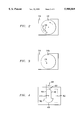
- FIG. 2 depicts a first embodiment of a rotatably-supported member having an asymmetric weight distribution.
- FIG. 3 depicts a first alternate embodiment of a rotatably-supported member having an asymmetric weight distribution.
- FIG. 4 depicts a second alternate embodiment of a rotatably-supported member having an asymmetric weight distribution.
- FIG. 5 depicts a third alternate embodiment of a rotatably-supported member having an asymmetric weight distribution.
- FIG. 6 depicts a first illustrative embodiment of a braking mechanism for slowing the motion of the movable assembly.
- FIG. 7 depicts a second illustrative embodiment of a braking mechanism for slowing the motion of the movable assembly.
- FIG. 8 depicts an agitator having dual movable assemblies in accordance with the present teachings.
- FIG. 9 depicts an agitator having a belt-drive system in accordance with the present teachings.
- FIG. 1 depicts agitator 102 in accordance with an illustrative embodiment of the present invention.
- Illustrative agitator 102 comprises movable assembly 104 which has a receiving surface 108.
- a container such as, for example, a microtiter plate, a flask, a test-tube rack containing test-tubes, or the like is placed on receiving surface 108.
- receiving surface 108 includes guides or other structures (not shown) for preventing a container from sliding off of the receiving surface 108 when assembly 104 is in motion.
- movable assembly 104 is suspended within frame 130 via resilient supports 128 that attach to lower plate 112 of the movable assembly.
- Frame 130 is advantageously rigid so that energy developed in movable assembly 104 is not dissipated within said frame.
- Frame 130 may be suitably formed, for example, from plastic.
- frame 130 is advantageously attachable to a supporting surface (e.g., bench top), or otherwise capable of being immobilized, so that energy developed in the movable assembly does not cause agitator 102 to move or "walk" across the supporting surface.
- attachment devices 132 realized in the illustrated embodiment as suction cups depending from frame 130, temporarily secure said frame to a supporting surface.
- resilient supports 128 are springs. It should be understood, however, that other devices or arrangements possessing the characteristic resilience of a spring and its ability to store energy under compression and tension, may suitably be used as resilient supports 128.
- movable assembly 104 comprises spaced upper and lower plates 106 and 112, respectively. Posts or the like (not shown), are used for spacing the upper and lower plates.
- Rotatably-supported member 118 shown in partial section for clarity of illustration, is disposed in the space between the upper and lower plates.
- rotatably-supported member 118 is rotatable about pin 126 that passes through said rotatably-supported member 118 and defines the rotational axis 1--1 thereof.
- rotational axis 1--1 is advantageously located at the geometric center 105 of movable assembly 104 and at the center 119 of rotatably-supported member 118.
- Pin 126 is received by a retaining member (not shown) located on inner opposed surfaces 110 and 114 of each of respective upper and lower plates 106 and 112.
- the retaining member is simply a hole in each plate that receives pin 126.
- the mass of rotatably-supported member 118 is asymmetrically distributed about rotational axis 1--1 (hereinafter referred to as an "asymmetrical mass distribution").
- asymmetrical mass distribution may be accomplished in a variety of ways, as described below.
- an asymmetric mass distribution is achieved by increasing the mass of the rotatably-supported member 118 at a selected eccentric location (i.e., not situated at the geometric center 119 and rotational axis 1--1 of rotatably supported member 118), such as location 120.
- a selected eccentric location i.e., not situated at the geometric center 119 and rotational axis 1--1 of rotatably supported member 118
- load element 122 in bore 121 at location 120.
- plan view in FIG. 2 The aforementioned arrangement wherein an additional mass is located off the rotational axis is illustrated by plan view in FIG. 2.
- an asymmetric mass loading is achieved by locating the rotational axis of rotatably-supported member 118a at an off-center location 316.
- an asymmetric mass loading is achieved by providing an asymmetrically-shaped rotatably-supported member 118b.
- weight 562 is engaged to rod 564 such that the weight is movable along the rod in a radial direction.
- rod 564 may be implemented as a screw
- weight 562 may be implemented as a nut, with the nut and screw joined in threaded engagement.
- Drive 133 causes rotatably-supported member 118 to rotate. Due to the asymmetric mass distribution of rotatably-supported member 118, force is non-uniformly applied to resilient supports 128 such that, at any given time, two of such resilient supports are subjected to a compressive force while the other two resilient supports are placed under tension.
- the two resilient supports that are subjected to the compressive force change as a function of the rotation of rotatably-supported member 118 (i.e., the angular position of load element 122), thereby guiding movable assembly 104 in orbital motion.
- illustrative agitator 102 of FIG. 1 advantageously returns movable assembly 104 to a "zero" or “home” position when agitation motion ceases.
- agitator 102 such a homing function is provided by resilient supports 128.
- the four identical resilient supports 128 of agitator 102 advantageously return movable assembly 104 to the center of stationary frame 130.
- an agitator in accordance with the present teachings includes a secondary support device for keeping movable assembly 104 suspended above the supporting surface (e.g., bench top).
- a secondary support device for keeping movable assembly 104 suspended above the supporting surface (e.g., bench top).
- a secondary support device is realized as distribution plate 140.
- Distribution plate 140 includes a plurality of holes 142 and a feed line (not shown).
- Compressed air or other conveniently available gas/vapor (hereinafter “lift gas”) is directed through the feed line and into distribution plate 140.
- the lift gas flows through holes 142 impacting lower surface 116 of lower plate 112 of movable assembly 104.
- the force of the lift gas against lower surface 116 "floats" movable assembly 104 ensuring that, in use, the movable assembly does not contact the support surface, which contact would hinder motion.
- rotatably-supported member 118 is driven by compressed air, or another conveniently available gas/vapor (hereinafter "drive gas").
- the drive gas is advantageously delivered to rotatably-supported member 118 via nozzle 136 that depends from an end of drive gas feed conduit 134.
- Nozzle end 138 directs drive gas between upper and lower plates 106 and 112 of movable member 104 towards rotatably-supported member 118. More particularly, nozzle end 138 delivers the drive gas to the perimeter of rotatably-supported member 118 along a path that is substantially tangential to said perimeter.
- Drive gas impacting the perimeter of rotatably-supported member 118 causes the rotatably-supported member to rotate.
- the rate of rotation of movable member 118 is primarily dependent upon the rate of flow of the drive gas from nozzle end 138 and the efficiency of energy transfer from the drive gas to movable member 118.
- the perimeter of the rotatably-supported member is physically adapted, in some embodiments, to capture the tangentially-directed drive gas.
- such an adaptation takes the form of uniform serrations 124, akin to the circumferentially-disposed "teeth" of a gear.
- the physical adaptation can be circumferentially-disposed "vanes,” as used in turbines.
- the rotatably-supported member 118 can be optimized for energy capture, wherein, for example, the serrations may be non-uniform in size and/or spacing.
- an agitator in accordance with the present invention includes, in some embodiments, a braking mechanism.
- a braking mechanism consists of spring-loaded braking brush 666 actuated by auxiliary gas nozzle 674 fed by conduit 672.
- auxiliary gas nozzle 674 fed by conduit 672.
- a slip-stream of drive gas is diverted, via conduit 672, to receiving surface 670 of braking brush 666.
- the force of the gas against receiving surface 670 overcomes the tendency of a biasing member (not shown) to bias braking surface 668 against rotatably-supported member 118.
- FIG. 7 depicts a second embodiment of a braking mechanism that is particularly well suited for use with agitators that utilize a load element (see FIGS. 2 and 5) for providing the required asymmetric mass distribution.
- the braking mechanism comprises an electrically-activated magnet, depicted as poles 776 and 778, that is disposed within the lower plate 112 or upper plate 106 of the movable assembly 104.
- the load element advantageously comprises a magnetic material.
- the characteristics of the orbital motion of movable platform 104 are primarily dependent upon (1) geometric parameters; (2) the "spring" constant of the resilient supports; (3) the specifics of the asymmetric weight distribution; and (4) the rate of rotation of the rotatably-supported member 118. The effect of each of such parameters on the orbital motion of movable platform 104 is described below.
- Geometric parameters determine the precise shape of the orbital motion. More particularly, with regard to illustrative agitator 102, one resilient support 128 depends from each corner of rectangularly-shaped lower plate 112 of movable assembly 104. For such an arrangement, the "orbit" is oval or ellipsoidal in shape. In another embodiment, a circular orbit is obtained by moving the attachment points of resilient supports 128 inwardly along long edges 115 of lower plate 112 such that the attachment points define a square. A circular orbital motion can also be obtained by attaching the resilient supports 128 to the corners of a square-shaped lower plate.
- the amplitude of motion of movable assembly 104 is determined, in part, by the "spring" constant of resilient supports 128.
- the spring constant and the amplitude of motion have an inverse relationship. For example, a relatively larger spring constant results in a relatively smaller amplitude of motion, and vice versa.
- the amplitude of motion is influenced by the asymmetric mass distribution of rotatably-supported member 118. More particularly, with respect to the illustrative embodiment depicted in FIG. 1, the radial position and weight of load element 122 influences amplitude. The closer that load element 122 is to the perimeter of rotatably-supported member 118, or the greater the weight of load element 122, the larger the amplitude of motion.
- the frequency of the orbital motion of movable assembly 104 is determined by rate at which rotatably-supported member 118 is driven.
- Such desired agitation behavior can then be associated with a specific revolutions-per-minute (rpm) of rotatably-supported member 118 in a variety of ways known in the art.
- rpm can be electrically determined using a magnetic pick-up coil and a frequency meter or oscilloscope, or optically determined via a stroboscope.
- the desired agitation behavior can be associated with a specific drive gas flow rate by placing a flow meter in-line and noting the flow rate at the onset of the desired agitation behavior.
- Illustrative agitator 102 provides a simple, reliable device for generating a vortex within a substance contained in a vessel.
- FIG. 8 depicts a second illustrative embodiment of an agitator 802 in accordance with the present teachings.
- Agitator 802 is adapted to provide random and very efficient mixing action.
- upper movable assembly 880 is suspended within frame 886 by resilient supports 884.
- Frame 886 is disposed on upper surface 808 of top plate 806 of lower movable assembly 804.
- Frame 886 can be formed integrally with upper plate 806, (e.g., molded as part of upper plate 806) or, alternatively, can be suitably attached to upper plate 806 in any convenient manner (e.g., epoxy, etc.).
- Sufficient spacing should be provided between upper movable assembly 880 and upper surface 808 so that when a container is placed on the upper movable assembly, it does not "bottom out," touching upper surface 808. Such spacing is dependent upon the height of the frame 886 above upper surface 808 and the spring constant of resilient supports 884.
- a portion of upper plate 806 can be removed such that upper movable assembly 880 is suspended by resilient supports 884 within such a cut-out region.
- frame 886 may not be necessary.
- resilient supports 884 can be attached directly to upper plate 806. Care must be taken to ensure that when a container is placed on upper movable platform 880, the weight of such a container does not force the upper movable assembly to contact first rotatably-supported member 818.
- Upper and lower movable assemblies 804 and 880 are arranged in the manner of movable assembly 104 of FIG. 1.
- Upper movable assembly 880 includes second rotatably-supported member 882 having an asymmetric weight distribution, drive gas feed conduit 888, nozzle 890, and the like.
- Agitator 802 allows for the generation of random and very efficient mixing motion via the superimposition of different rotation patterns generated by the two movable plates.
- the agitators were able to generate a vortex in the wells of 96-, 384- and 1536-well microtiter plates.
- the upper and lower plates e.g., plates 106 and 112 of agitator 102
- Conventional "expansion-type" springs were used as the resilient supports (e.g., supports 128 of agitator 102).
- the springs used in the agitators had spring constants in the range of from about 0.8 to 65 lb/inch.
- the spring constant was selected based on several performance considerations. Such considerations included, for example, avoiding system resonance over the expected operating frequencies and obtaining a suitable amplitude of deflection, among other considerations.
- All rotationally-supported members were made from plastic, including DelrinTM, which is an acetal-based plastic made by DuPont, Nylon and Fiberglass. High speed ball bearings, as well as self-lubricating composite bearings, were used in conjunction with the rotatably-supported member.
- the rotational speed for developing a vortex within wells of the microtiter plates varied as a function of well size.
- vortexing began at about 1300 RPM of the rotatably-supported member.
- vortexing was observed in the range of about 10,000 RPM.
- the above-described illustrative embodiments of the present agitator use a "direct"- drive system.
- the action of the drive gas against the rotatably-supported member drives said rotatably-supported member.
- a direct-drive system is particularly well suited for generating relatively higher agitation rates, other arrangements are advantageously used when lower agitation rates are desired.
- Lower agitation rates may be desired, for example, when attempting to develop a vortex within a fluid contained in a vessel having a very large diameter (there is an inverse relationship between the agitation speed required for vortexing and container diameter).
- FIG. 9 depicts an exploded view of an illustrative embodiment of an agitator 902 particularly well suited for generating lower agitation rates.
- Agitator 902 advantageously incorporates a belt-drive system for driving the rotatably-supported member.
- the overall layout of agitator 902 is similar to the previously-described illustrative agitators.
- agitator 902 comprises movable assembly 904 which has a receiving surface 908.
- Movable assembly 904 is suspended within frame 930 via resilient supports 928 that attach to lower plate 912 of the movable assembly.
- Movable assembly 904 comprises spaced upper and lower plates 906 and 912, respectively.
- movable assembly 904 is depicted with upper plate 906 removed so that rotatably-supported member 918 and the drive system, which in illustrative agitator 902 are disposed on lower plate 912, are visible.
- Separators 911 are used for spacing the upper and lower plates 906 and 912.
- rotatably-supported member 918 is rotatable about pin 926 that passes through it and defines the rotational axis thereof. Like agitator 102, the mass of rotatably-supported member 918 is asymmetrically distributed about its rotational axis. In the illustrated embodiment, such an asymmetrical mass distribution is achieved utilizing an eccentrically located (i.e., not aligned with the rotational axis) loading element 922. As the rotatably-supported member 918 rotates, force is non-uniformly applied to resilient supports 928 due to the asymmetric mass distribution of the rotatably-supported member. As a result, movable assembly 904 is guided into orbital motion as previously described.
- illustrative agitator 902 is advantageously structured to return movable assembly 904 to a home position when agitating motion ceases. Since agitator 902 will typically be agitating relatively massive loads, it advantageously includes a secondary support device for providing additional support for movable assembly 904. In the illustrated embodiment, the secondary support device is realized as distribution plate 940, configured in the manner of distribution plate 140, previously described. (See FIG. 1 and accompanying description). Moreover, agitator 902 advantageously includes a braking mechanism (not shown), such as previously described.
- Illustrative agitator 902 utilizes a belt-drive system for driving the rotatably-supported member, as opposed to the direct-drive system of agitators 102 and 802.
- the belt-drive system includes a rotatable drive member 992, pulley 996, belt 998, nozzle 936 and drive gas feed conduit 934.
- drive gas e.g., compressed air or other suitable fluid
- nozzle 936 that depends from an end of drive gas feed conduit 934.
- Nozzle end 938 directs drive gas towards the perimeter 994 of drive member 992 along a path that is substantially tangential to said perimeter.
- Drive gas impacting the perimeter of drive member 992 causes the drive member to rotate.
- the perimeter of drive member 992 is advantageously physically adapted to capture the tangentially-directed drive gas using uniform serrations, vanes, teeth and the like.
- An arrangement for transferring the rotation of drive member 992 to rotatably-supported member 918 is provided.
- the arrangement consists of pulley 996 that is rigidly attached to drive member 992, and belt 998 that mechanically links pulley 996 to rotatably-supported member 918.
- agitator 902 In embodiments in which agitator 902 is intended to agitate materials contained in very large vessels, the agitator provides a low agitation rate. Consequently, rotatably-supported member 918 should be driven at a low rate of speed. Turning down the flow of compressed air to slow the rate of rotation of rotatably-supported member 918 may become problematic once a certain minimum flow rate is reached. As an alternative, a low drive speed may be obtained by providing pulley 996 having a smaller circumference than that of drive member 992. It will be appreciated that, when the drive system is so configured, the velocity of pulley 996 at its perimeter is lower than the velocity of drive member 992 at its perimeter.
- rotatably-supported member 918 driven by pulley 996, rotates at a lower rpm than drive member 992.
- the rate of rotation of rotatably-supported member 918 may be reduced to very low speeds while drive gas flow is maintained at a suitably high rate.
- An agitator incorporating a belt-drive system for driving the rotatably-supported member was fabricated. All parts were made out of plastic.
- the rotatably-supported member is a glass-filled nylon, and the weights used to provide the mass loading were either steel inserts or lead that was poured into a pre-drilled cavity in the rotatably-supported member.
- the pulley was made of DelrinTM (DuPont), and bearings for the rotatable members were ball bearings or non metallic bearings such as RulonTM J available from Dixon Industries.
- a "friction-type" belt e.g., an O-ring
- PolycordTM available from SMI Small Parts Inc. of Miami Lakes, Fla.
- the upper and lower plates were substantially larger than those used for the agitators described in EXAMPLE 1, and were able to support a vessel having a diameter as large as about 10 inches.
- the agitator developed a maximum agitation speed of about 1000 rpm.
Abstract
Description
Claims (20)
Priority Applications (7)
| Application Number | Priority Date | Filing Date | Title |
|---|---|---|---|
| US09/124,497 US5988869A (en) | 1998-07-29 | 1998-07-29 | Agitator for orbital agitation |
| PCT/US1999/015883 WO2000006294A1 (en) | 1998-07-29 | 1999-07-13 | Agitation device |
| EP99934000A EP1107822A4 (en) | 1998-07-29 | 1999-07-13 | Agitation device |
| AU49928/99A AU737247C (en) | 1998-07-29 | 1999-07-13 | Agitation device |
| CA002338284A CA2338284A1 (en) | 1998-07-29 | 1999-07-13 | Agitation device |
| IL14059799A IL140597A0 (en) | 1998-07-29 | 1999-07-13 | Agitation device |
| JP2000562136A JP2002521191A (en) | 1998-07-29 | 1999-07-13 | Stirrer |
Applications Claiming Priority (1)
| Application Number | Priority Date | Filing Date | Title |
|---|---|---|---|
| US09/124,497 US5988869A (en) | 1998-07-29 | 1998-07-29 | Agitator for orbital agitation |
Publications (1)
| Publication Number | Publication Date |
|---|---|
| US5988869A true US5988869A (en) | 1999-11-23 |
Family
ID=22415224
Family Applications (1)
| Application Number | Title | Priority Date | Filing Date |
|---|---|---|---|
| US09/124,497 Expired - Lifetime US5988869A (en) | 1998-07-29 | 1998-07-29 | Agitator for orbital agitation |
Country Status (7)
| Country | Link |
|---|---|
| US (1) | US5988869A (en) |
| EP (1) | EP1107822A4 (en) |
| JP (1) | JP2002521191A (en) |
| AU (1) | AU737247C (en) |
| CA (1) | CA2338284A1 (en) |
| IL (1) | IL140597A0 (en) |
| WO (1) | WO2000006294A1 (en) |
Cited By (14)
| Publication number | Priority date | Publication date | Assignee | Title |
|---|---|---|---|---|
| US6299344B1 (en) * | 1998-10-05 | 2001-10-09 | New Brunswick Scientific Company | Flexible band reciprocating shaker |
| US20020098117A1 (en) * | 1998-05-01 | 2002-07-25 | Gen-Probe Incorporated | Incubator for use in an automated diagnostic analyzer |
| US20040042339A1 (en) * | 2002-08-27 | 2004-03-04 | Gebrian Peter Louis | Method and apparatus for mixing liquid samples using a sinusoidal mixing action |
| US20050190641A1 (en) * | 2004-02-28 | 2005-09-01 | Countz John W. | Method and system for mixing fingernail polish |
| US20060152999A1 (en) * | 2005-01-10 | 2006-07-13 | Dunfee William D | Method and apparatus for mixing liquid samples in a container using a two dimensional stirring pattern |
| US7794659B2 (en) | 2005-03-10 | 2010-09-14 | Gen-Probe Incorporated | Signal measuring system having a movable signal measuring device |
| US20100284238A1 (en) * | 2007-03-02 | 2010-11-11 | Manfred Ebers | Multistation Device for Mixing the Contents of Laboratory Vessels |
| US8192992B2 (en) | 1998-05-01 | 2012-06-05 | Gen-Probe Incorporated | System and method for incubating the contents of a reaction receptacle |
| US8718948B2 (en) | 2011-02-24 | 2014-05-06 | Gen-Probe Incorporated | Systems and methods for distinguishing optical signals of different modulation frequencies in an optical signal detector |
| US8876361B2 (en) | 2008-03-28 | 2014-11-04 | Arkray, Inc. | Fluid agitation method, fluid agitation system, and cartridge |
| US9046507B2 (en) | 2010-07-29 | 2015-06-02 | Gen-Probe Incorporated | Method, system and apparatus for incorporating capacitive proximity sensing in an automated fluid transfer procedure |
| US9335338B2 (en) | 2013-03-15 | 2016-05-10 | Toshiba Medical Systems Corporation | Automated diagnostic analyzers having rear accessible track systems and related methods |
| US9400285B2 (en) | 2013-03-15 | 2016-07-26 | Abbot Laboratories | Automated diagnostic analyzers having vertically arranged carousels and related methods |
| US10001497B2 (en) | 2013-03-15 | 2018-06-19 | Abbott Laboratories | Diagnostic analyzers with pretreatment carousels and related methods |
Families Citing this family (3)
| Publication number | Priority date | Publication date | Assignee | Title |
|---|---|---|---|---|
| DE102008008086B3 (en) * | 2008-01-28 | 2009-07-23 | Herbert Rieger | Fermentation tank for the treatment of red wine mash |
| JP7178012B2 (en) * | 2018-10-29 | 2022-11-25 | 学校法人 中央大学 | Liquid mixing device and liquid mixing method |
| CN113617269B (en) * | 2021-09-24 | 2022-03-22 | 无锡市第五人民医院 | Test tube oscillation equipment for hospital clinical laboratory |
Citations (16)
| Publication number | Priority date | Publication date | Assignee | Title |
|---|---|---|---|---|
| US1767601A (en) * | 1930-02-10 | 1930-06-24 | Earl R Miller | Agitator |
| US3128082A (en) * | 1962-03-02 | 1964-04-07 | Claude D Cline | Shaker |
| US3539156A (en) * | 1967-01-17 | 1970-11-10 | Manfred Zipperer | Vibrator or shaker |
| GB1387402A (en) * | 1971-03-02 | 1975-03-19 | Techno Med Ltd | Mixing process and apparatus |
| US4125335A (en) * | 1977-02-03 | 1978-11-14 | Blume Horst K | Agitator system |
| US4147516A (en) * | 1976-04-09 | 1979-04-03 | Debruyne Norman A | Oscillatory mechanisms |
| US4183677A (en) * | 1977-09-07 | 1980-01-15 | Bruyne Norman A De | Mechanism for effecting orbital motion of a member |
| US4422768A (en) * | 1982-03-22 | 1983-12-27 | Roy Brodshy | Paint can shaker |
| US4619532A (en) * | 1984-11-29 | 1986-10-28 | Everett Douglas Hougen | Shaker for paint containers |
| US4702610A (en) * | 1985-04-18 | 1987-10-27 | Reynolds Jr Albert B | Undulating mixing device |
| US4834548A (en) * | 1985-02-12 | 1989-05-30 | Skandex Ab | Apparatus for agitating the content of a closed package |
| US4929087A (en) * | 1986-04-02 | 1990-05-29 | Societe Anonyme Des Machines Osborn | Method for applying vibrations to a resilient support and apparatus for putting this method into practice |
| JPH02187138A (en) * | 1989-01-17 | 1990-07-23 | Taiyo Kagaku Kogyo Kk | Reciprocation-rotation switching-type shaker |
| US5593228A (en) * | 1996-05-03 | 1997-01-14 | New Brunswick Scientific Co., Inc. | Rotary shaker with flexible strap suspension |
| US5655836A (en) * | 1995-09-01 | 1997-08-12 | Preston Industries, Inc. | Dual action shaker table using parallelogram linkages |
| US5833362A (en) * | 1997-05-06 | 1998-11-10 | Shepard; James | Beverage blender |
Family Cites Families (5)
| Publication number | Priority date | Publication date | Assignee | Title |
|---|---|---|---|---|
| US2559620A (en) * | 1946-12-17 | 1951-07-10 | High Rie | Air driven shaker |
| US3217531A (en) * | 1957-09-27 | 1965-11-16 | Gen Dynamics Corp | Vibration table supported on fluid film |
| FR1271934A (en) * | 1960-10-25 | 1961-09-15 | Agfa Ag | Controller for intimate mixing of liquids in small photographic processing devices |
| US3348278A (en) * | 1965-01-06 | 1967-10-24 | Jankovsky Ivan Pavlovich | Air suspended vibrational mold |
| FR2587917B1 (en) * | 1985-10-01 | 1990-08-10 | Cogema | PNEUMATIC AGITATOR |
-
1998
- 1998-07-29 US US09/124,497 patent/US5988869A/en not_active Expired - Lifetime
-
1999
- 1999-07-13 WO PCT/US1999/015883 patent/WO2000006294A1/en not_active Application Discontinuation
- 1999-07-13 CA CA002338284A patent/CA2338284A1/en not_active Abandoned
- 1999-07-13 AU AU49928/99A patent/AU737247C/en not_active Ceased
- 1999-07-13 JP JP2000562136A patent/JP2002521191A/en not_active Withdrawn
- 1999-07-13 EP EP99934000A patent/EP1107822A4/en not_active Withdrawn
- 1999-07-13 IL IL14059799A patent/IL140597A0/en unknown
Patent Citations (16)
| Publication number | Priority date | Publication date | Assignee | Title |
|---|---|---|---|---|
| US1767601A (en) * | 1930-02-10 | 1930-06-24 | Earl R Miller | Agitator |
| US3128082A (en) * | 1962-03-02 | 1964-04-07 | Claude D Cline | Shaker |
| US3539156A (en) * | 1967-01-17 | 1970-11-10 | Manfred Zipperer | Vibrator or shaker |
| GB1387402A (en) * | 1971-03-02 | 1975-03-19 | Techno Med Ltd | Mixing process and apparatus |
| US4147516A (en) * | 1976-04-09 | 1979-04-03 | Debruyne Norman A | Oscillatory mechanisms |
| US4125335A (en) * | 1977-02-03 | 1978-11-14 | Blume Horst K | Agitator system |
| US4183677A (en) * | 1977-09-07 | 1980-01-15 | Bruyne Norman A De | Mechanism for effecting orbital motion of a member |
| US4422768A (en) * | 1982-03-22 | 1983-12-27 | Roy Brodshy | Paint can shaker |
| US4619532A (en) * | 1984-11-29 | 1986-10-28 | Everett Douglas Hougen | Shaker for paint containers |
| US4834548A (en) * | 1985-02-12 | 1989-05-30 | Skandex Ab | Apparatus for agitating the content of a closed package |
| US4702610A (en) * | 1985-04-18 | 1987-10-27 | Reynolds Jr Albert B | Undulating mixing device |
| US4929087A (en) * | 1986-04-02 | 1990-05-29 | Societe Anonyme Des Machines Osborn | Method for applying vibrations to a resilient support and apparatus for putting this method into practice |
| JPH02187138A (en) * | 1989-01-17 | 1990-07-23 | Taiyo Kagaku Kogyo Kk | Reciprocation-rotation switching-type shaker |
| US5655836A (en) * | 1995-09-01 | 1997-08-12 | Preston Industries, Inc. | Dual action shaker table using parallelogram linkages |
| US5593228A (en) * | 1996-05-03 | 1997-01-14 | New Brunswick Scientific Co., Inc. | Rotary shaker with flexible strap suspension |
| US5833362A (en) * | 1997-05-06 | 1998-11-10 | Shepard; James | Beverage blender |
Non-Patent Citations (2)
| Title |
|---|
| Product Brochure: Elmeco s Line of Mixers, The Rock N Roller, Mar. 1996. * |
| Product Brochure: Elmeco's Line of Mixers, The Rock `N` Roller, Mar. 1996. |
Cited By (54)
| Publication number | Priority date | Publication date | Assignee | Title |
|---|---|---|---|---|
| US8012419B2 (en) | 1998-05-01 | 2011-09-06 | Gen-Probe Incorporated | Temperature-controlled incubator having rotatable door |
| US6605213B1 (en) * | 1998-05-01 | 2003-08-12 | Gen-Probe Incorporated | Method and apparatus for performing a magnetic separation purification procedure on a sample solution |
| US9150908B2 (en) | 1998-05-01 | 2015-10-06 | Gen-Probe Incorporated | Method for detecting the presence of a nucleic acid in a sample |
| US8883455B2 (en) | 1998-05-01 | 2014-11-11 | Gen-Probe Incorporated | Method for detecting the presence of a nucleic acid in a sample |
| US6764649B2 (en) | 1998-05-01 | 2004-07-20 | Gen-Probe Incorporated | Transport mechanism |
| US9598723B2 (en) | 1998-05-01 | 2017-03-21 | Gen-Probe Incorporated | Automated analyzer for performing a nucleic acid-based assay |
| US8318500B2 (en) | 1998-05-01 | 2012-11-27 | Gen-Probe, Incorporated | Method for agitating the contents of a reaction receptacle within a temperature-controlled environment |
| US20050239127A1 (en) * | 1998-05-01 | 2005-10-27 | Gen-Probe Incorporated | Automated process for isolating and amplifying a target nucleic acid sequence using a robotic pipettor |
| US8309358B2 (en) | 1998-05-01 | 2012-11-13 | Gen-Probe Incorporated | Method for introducing a fluid into a reaction receptacle contained within a temperature-controlled environment |
| US8221682B2 (en) | 1998-05-01 | 2012-07-17 | Gen-Probe Incorporated | System for incubating the contents of a reaction receptacle |
| US7666602B2 (en) | 1998-05-01 | 2010-02-23 | Gen-Probe Incorporated | Method for agitating the fluid contents of a container |
| US7666681B2 (en) | 1998-05-01 | 2010-02-23 | Gen-Probe Incorporated | Method for agitating the fluid contents of a container |
| US8337753B2 (en) | 1998-05-01 | 2012-12-25 | Gen-Probe Incorporated | Temperature-controlled incubator having a receptacle mixing mechanism |
| US20020098117A1 (en) * | 1998-05-01 | 2002-07-25 | Gen-Probe Incorporated | Incubator for use in an automated diagnostic analyzer |
| US8192992B2 (en) | 1998-05-01 | 2012-06-05 | Gen-Probe Incorporated | System and method for incubating the contents of a reaction receptacle |
| US8709814B2 (en) | 1998-05-01 | 2014-04-29 | Gen-Probe Incorporated | Method for incubating the contents of a receptacle |
| US8569020B2 (en) | 1998-05-01 | 2013-10-29 | Gen-Probe Incorporated | Method for simultaneously performing multiple amplification reactions |
| US8569019B2 (en) | 1998-05-01 | 2013-10-29 | Gen-Probe Incorporated | Method for performing an assay with a nucleic acid present in a specimen |
| US8137620B2 (en) | 1998-05-01 | 2012-03-20 | Gen-Probe Incorporated | Temperature-controlled incubator having an arcuate closure panel |
| US8546110B2 (en) | 1998-05-01 | 2013-10-01 | Gen-Probe Incorporated | Method for detecting the presence of a nucleic acid in a sample |
| US6299344B1 (en) * | 1998-10-05 | 2001-10-09 | New Brunswick Scientific Company | Flexible band reciprocating shaker |
| US20040042339A1 (en) * | 2002-08-27 | 2004-03-04 | Gebrian Peter Louis | Method and apparatus for mixing liquid samples using a sinusoidal mixing action |
| US6808304B2 (en) * | 2002-08-27 | 2004-10-26 | Dade Behring Inc. | Method for mixing liquid samples using a linear oscillation stroke |
| US20050190641A1 (en) * | 2004-02-28 | 2005-09-01 | Countz John W. | Method and system for mixing fingernail polish |
| US7258480B2 (en) | 2005-01-10 | 2007-08-21 | Dade Behring Inc. | Apparatus for mixing liquid samples using a two dimensional stirring pattern |
| US20060152999A1 (en) * | 2005-01-10 | 2006-07-13 | Dunfee William D | Method and apparatus for mixing liquid samples in a container using a two dimensional stirring pattern |
| US8349564B2 (en) | 2005-03-10 | 2013-01-08 | Gen-Probe Incorporated | Method for continuous mode processing of the contents of multiple reaction receptacles in a real-time amplification assay |
| US8501461B2 (en) | 2005-03-10 | 2013-08-06 | Gen-Probe Incorporated | System for performing multi-formatted assays |
| US9726607B2 (en) | 2005-03-10 | 2017-08-08 | Gen-Probe Incorporated | Systems and methods for detecting multiple optical signals |
| US8008066B2 (en) | 2005-03-10 | 2011-08-30 | Gen-Probe Incorporated | System for performing multi-formatted assays |
| US7964413B2 (en) | 2005-03-10 | 2011-06-21 | Gen-Probe Incorporated | Method for continuous mode processing of multiple reaction receptacles in a real-time amplification assay |
| US8615368B2 (en) | 2005-03-10 | 2013-12-24 | Gen-Probe Incorporated | Method for determining the amount of an analyte in a sample |
| US8663922B2 (en) | 2005-03-10 | 2014-03-04 | Gen-Probe Incorporated | Systems and methods for detecting multiple optical signals |
| US7932081B2 (en) | 2005-03-10 | 2011-04-26 | Gen-Probe Incorporated | Signal measuring system for conducting real-time amplification assays |
| US7794659B2 (en) | 2005-03-10 | 2010-09-14 | Gen-Probe Incorporated | Signal measuring system having a movable signal measuring device |
| US9372156B2 (en) | 2005-03-10 | 2016-06-21 | Gen-Probe Incorporated | System for processing contents of a receptacle to detect an optical signal emitted by the contents |
| US7897337B2 (en) | 2005-03-10 | 2011-03-01 | Gen-Probe Incorporated | Method for performing multi-formatted assays |
| US10006862B2 (en) | 2005-03-10 | 2018-06-26 | Gen-Probe Incorporated | Continuous process for performing multiple nucleic acid amplification assays |
| US20100284238A1 (en) * | 2007-03-02 | 2010-11-11 | Manfred Ebers | Multistation Device for Mixing the Contents of Laboratory Vessels |
| US8016478B2 (en) * | 2007-03-02 | 2011-09-13 | Eppendorf Ag | Multistation device for mixing the contents of laboratory vessels |
| US8876361B2 (en) | 2008-03-28 | 2014-11-04 | Arkray, Inc. | Fluid agitation method, fluid agitation system, and cartridge |
| US9046507B2 (en) | 2010-07-29 | 2015-06-02 | Gen-Probe Incorporated | Method, system and apparatus for incorporating capacitive proximity sensing in an automated fluid transfer procedure |
| US10641707B2 (en) | 2011-02-24 | 2020-05-05 | Gen-Probe Incorporated | Systems and methods for distinguishing optical signals of different modulation frequencies in an optical signal detector |
| US8718948B2 (en) | 2011-02-24 | 2014-05-06 | Gen-Probe Incorporated | Systems and methods for distinguishing optical signals of different modulation frequencies in an optical signal detector |
| US9915613B2 (en) | 2011-02-24 | 2018-03-13 | Gen-Probe Incorporated | Systems and methods for distinguishing optical signals of different modulation frequencies in an optical signal detector |
| US9335338B2 (en) | 2013-03-15 | 2016-05-10 | Toshiba Medical Systems Corporation | Automated diagnostic analyzers having rear accessible track systems and related methods |
| US10001497B2 (en) | 2013-03-15 | 2018-06-19 | Abbott Laboratories | Diagnostic analyzers with pretreatment carousels and related methods |
| US10197585B2 (en) | 2013-03-15 | 2019-02-05 | Abbott Laboratories | Automated diagnostic analyzers having vertically arranged carousels and related methods |
| US10267818B2 (en) | 2013-03-15 | 2019-04-23 | Abbott Laboratories | Automated diagnostic analyzers having rear accessible track systems and related methods |
| US9400285B2 (en) | 2013-03-15 | 2016-07-26 | Abbot Laboratories | Automated diagnostic analyzers having vertically arranged carousels and related methods |
| US10775398B2 (en) | 2013-03-15 | 2020-09-15 | Abbott Laboratories | Automated diagnostic analyzers having vertically arranged carousels and related methods |
| US11125766B2 (en) | 2013-03-15 | 2021-09-21 | Abbott Laboratories | Automated diagnostic analyzers having rear accessible track systems and related methods |
| US11435372B2 (en) | 2013-03-15 | 2022-09-06 | Abbott Laboratories | Diagnostic analyzers with pretreatment carousels and related methods |
| US11536739B2 (en) | 2013-03-15 | 2022-12-27 | Abbott Laboratories | Automated diagnostic analyzers having vertically arranged carousels and related methods |
Also Published As
| Publication number | Publication date |
|---|---|
| JP2002521191A (en) | 2002-07-16 |
| EP1107822A4 (en) | 2002-11-27 |
| EP1107822A1 (en) | 2001-06-20 |
| AU737247B2 (en) | 2001-08-16 |
| AU4992899A (en) | 2000-02-21 |
| CA2338284A1 (en) | 2000-02-10 |
| WO2000006294A1 (en) | 2000-02-10 |
| IL140597A0 (en) | 2002-02-10 |
| AU737247C (en) | 2002-03-21 |
Similar Documents
| Publication | Publication Date | Title |
|---|---|---|
| US5988869A (en) | Agitator for orbital agitation | |
| AU618956B2 (en) | Device for mixing at least one aqueous fluid substance | |
| JP6629182B2 (en) | Device for delivering and agitating a fluid container | |
| US6659637B2 (en) | Vertical electromagnetic shaker for biological and chemical specimens | |
| US20170014787A1 (en) | Sample vessel agitation apparatus and method | |
| US5399013A (en) | Mixing device | |
| US5593228A (en) | Rotary shaker with flexible strap suspension | |
| US7210843B2 (en) | Multidirectional mixing of fluid samples | |
| US6508582B2 (en) | Electromagnetic vibratory microplate shaker | |
| US8016478B2 (en) | Multistation device for mixing the contents of laboratory vessels | |
| US7059763B2 (en) | Gyroscopic mixer | |
| EP0853493B1 (en) | Method and apparatus for vortex mixing using centrifugal force | |
| US4109319A (en) | Agitator for laboratory tubes and flasks and the like | |
| KR900002832A (en) | Automatic device causing vortex | |
| CA1208203A (en) | Paint mixing container clamping device with inertially driven can rotating function | |
| JPH02258041A (en) | Vortex generating device | |
| JP3580864B2 (en) | Stirrer | |
| US7296924B2 (en) | Vortexer | |
| US4362455A (en) | Vibrating bowl feeder | |
| US20030081499A1 (en) | Multidirectional shaker | |
| SU1105220A1 (en) | Vibration mixer | |
| GB2076677A (en) | Magnetic stirring elements | |
| US6585405B2 (en) | Mixing liquids and entrainment mixing of vapor into liquids | |
| JP3987210B2 (en) | Stirrer | |
| JP2866404B2 (en) | Centrifuge |
Legal Events
| Date | Code | Title | Description |
|---|---|---|---|
| AS | Assignment |
Owner name: PHARMACOPEIA, INC., NEW JERSEY Free format text: ASSIGNMENT OF ASSIGNORS INTEREST;ASSIGNORS:DAVIDSON, JEFFREY BRUCE;FEYGIN, ILYA;GASTGEB, RAYMOND FREDRICK;REEL/FRAME:009553/0763 Effective date: 19981014 |
|
| STCF | Information on status: patent grant |
Free format text: PATENTED CASE |
|
| AS | Assignment |
Owner name: IIYA FEYGIN, NEW JERSEY Free format text: ASSIGNMENT OF ASSIGNORS INTEREST;ASSIGNOR:PHARMACOPEIA, INC.;REEL/FRAME:013083/0081 Effective date: 20020429 |
|
| FEPP | Fee payment procedure |
Free format text: PAT HOLDER CLAIMS SMALL ENTITY STATUS, ENTITY STATUS SET TO SMALL (ORIGINAL EVENT CODE: LTOS); ENTITY STATUS OF PATENT OWNER: SMALL ENTITY |
|
| FPAY | Fee payment |
Year of fee payment: 4 |
|
| REMI | Maintenance fee reminder mailed | ||
| FEPP | Fee payment procedure |
Free format text: ENTITY STATUS SET TO SMALL (ORIGINAL EVENT CODE: SMAL); ENTITY STATUS OF PATENT OWNER: SMALL ENTITY |
|
| AS | Assignment |
Owner name: TECHELAN, LLC, NEW JERSEY Free format text: ASSIGNMENT OF ASSIGNORS INTEREST;ASSIGNOR:FEYGIN, ILYA;REEL/FRAME:015886/0903 Effective date: 20040329 |
|
| AS | Assignment |
Owner name: TECHELAN, LLC, NEW JERSEY Free format text: ASSIGNMENT OF ASSIGNORS INTEREST;ASSIGNOR:FEYGIN, ILYA;REEL/FRAME:016172/0708 Effective date: 20040329 Owner name: TECHELAN, LLC, NEW JERSEY Free format text: ASSIGNMENT OF ASSIGNORS INTEREST;ASSIGNOR:FEYGIN, LLYA;REEL/FRAME:016172/0866 Effective date: 20040329 |
|
| FPAY | Fee payment |
Year of fee payment: 8 |
|
| FPAY | Fee payment |
Year of fee payment: 12 |