US5995256A - Method and system for managing optical subcarrier reception - Google Patents
Method and system for managing optical subcarrier reception Download PDFInfo
- Publication number
- US5995256A US5995256A US08/941,546 US94154697A US5995256A US 5995256 A US5995256 A US 5995256A US 94154697 A US94154697 A US 94154697A US 5995256 A US5995256 A US 5995256A
- Authority
- US
- United States
- Prior art keywords
- subcarrier
- signal
- wavelength
- modulation signal
- modulated optical
- Prior art date
- Legal status (The legal status is an assumption and is not a legal conclusion. Google has not performed a legal analysis and makes no representation as to the accuracy of the status listed.)
- Expired - Lifetime
Links
Images


Classifications
-
- H—ELECTRICITY
- H04—ELECTRIC COMMUNICATION TECHNIQUE
- H04Q—SELECTING
- H04Q11/00—Selecting arrangements for multiplex systems
- H04Q11/0001—Selecting arrangements for multiplex systems using optical switching
-
- H—ELECTRICITY
- H04—ELECTRIC COMMUNICATION TECHNIQUE
- H04J—MULTIPLEX COMMUNICATION
- H04J14/00—Optical multiplex systems
- H04J14/02—Wavelength-division multiplex systems
- H04J14/0227—Operation, administration, maintenance or provisioning [OAMP] of WDM networks, e.g. media access, routing or wavelength allocation
- H04J14/0241—Wavelength allocation for communications one-to-one, e.g. unicasting wavelengths
-
- H—ELECTRICITY
- H04—ELECTRIC COMMUNICATION TECHNIQUE
- H04J—MULTIPLEX COMMUNICATION
- H04J14/00—Optical multiplex systems
- H04J14/02—Wavelength-division multiplex systems
- H04J14/0298—Wavelength-division multiplex systems with sub-carrier multiplexing [SCM]
-
- H—ELECTRICITY
- H04—ELECTRIC COMMUNICATION TECHNIQUE
- H04J—MULTIPLEX COMMUNICATION
- H04J14/00—Optical multiplex systems
- H04J14/02—Wavelength-division multiplex systems
- H04J14/0227—Operation, administration, maintenance or provisioning [OAMP] of WDM networks, e.g. media access, routing or wavelength allocation
-
- H—ELECTRICITY
- H04—ELECTRIC COMMUNICATION TECHNIQUE
- H04J—MULTIPLEX COMMUNICATION
- H04J14/00—Optical multiplex systems
- H04J14/02—Wavelength-division multiplex systems
- H04J14/0278—WDM optical network architectures
- H04J14/0284—WDM mesh architectures
-
- H—ELECTRICITY
- H04—ELECTRIC COMMUNICATION TECHNIQUE
- H04J—MULTIPLEX COMMUNICATION
- H04J14/00—Optical multiplex systems
- H04J14/02—Wavelength-division multiplex systems
- H04J14/0287—Protection in WDM systems
- H04J14/0293—Optical channel protection
Definitions
- the present invention relates to optical communication network management and services. Specifically, this invention relates to simultaneously applying a low-level subcarrier modulation signal to multiple high-bit-rate modulated optical data signals propagating through the same fiber or similar path.
- a slow response-time summing amplifier is utilized at a reception point in the optical communication network to sum individual subcarrier components and thereby create a high signal-to-noise ratio of subcarrier modulation signals within the subcarrier channel of the communication network.
- a typical communication network serving to transport information among a number of locations, consists of various physical sites, called nodes, interconnected by information conduits, called "links." Each link serves to carry information from one site to another site. Individual sites contain equipment for combining, separating, transforming, conditioning, and/or routing data.
- Optical networks that include a plurality of optical transmission lines or links permit high bandwidth data communications, and may be used in telephone and other data network systems.
- High speed data can be modulated on light waves which are transmitted through the optical network.
- the optical transmission line connecting an optical transmitter and receiver, can propagate many light wave signals of different frequencies simultaneously.
- One type of multi-frequency (or multi-wavelength) communication is found in wavelength-division-multiplexed (WDM) networks. See, e.g., U.S. Pat. No. 4,821,255, issued Apr. 11, 1989 to Kobrinski, incorporated herein by reference in its entirety.
- WDM wavelength-division-multiplexed
- Optical networks carry high-data rate traffic supporting an ever-increasing variety and range of interconnected data networks, lower-level networks, distributed systems, consumer communication products and services, and remote units. As the proliferation and diversity of network elements and signals becomes greater, network management becomes even more critical.
- a primary concern for network providers is accurately tracking the flow of data signals that traverse the communication network through various nodes, switching sites, and links.
- One method of tracking information without affecting the high data rate modulation signal is by providing ancillary network data as a rider on a high data rate modulated optical signal, as disclosed in the present inventor's related applications entitled “Method and System for Detecting LMink Failure in All Optical Communication Network,” Ser. No. 08/582,845, and "All Optical Network with Low Level Subcarrier for Ancillary Data,” Ser. No. 08/673,651.
- This subcarrier modulated signal can be used to monitor the status of the data signals, without having to alter the high data rate modulation signal itself.
- a low-level subcarrier signal can have a peak-to-peak intensity modulation that is a fraction of that of the high data rate modulated signal.
- a single period of the low-level subcarrier signal is then spread over thousands of high-rate bits and is readily separable by inexpensive optical detectors.
- Typical sources of noise within a communication network include: signal-spontaneous beat noise created from the subcarrier signal and the amplified stimulated emission (ASE) of optical amplifiers and regenerators; the spontaneous-spontaneous beat noise created by the ASE itself; shot noise created from the subcarrier signal and ASE; and thermal noise.
- ASE stimulated emission
- thermal noise For a discussion on the types of noise found in optical communication systems, see Murakami, et al., "A Remote Supervisory System Based on Subcarrier Overmodulation for Submarine Optical Amplifier Systems," Jour. of Lightwave Tech., Vol. 14, No.
- the subcarrier modulation signal must have a low amplitude as compared to the high data rate modulation signal (i.e., low enough to not interfere with reliable reception of the high-bit-rate signal), detection of the subcarrier signal is especially vulnerable to noise problems leading to a low SNR.
- the present invention provides a method and apparatus for high signal-to-noise ratio (SNR) optical subcarrier management and reception in a communication network.
- a subcarrier modulation signal carrying ancillary network data is generated by a subcarrier modulation signal generator at the first site.
- This subcarrier modulation signal has a lower frequency and lower amplitude than high data rate modulation signals transported by the network.
- the subcarrier modulation signal generator is part of a subcarrier channel of the communication network.
- the subcarrier channel is supported by network equipment that generates, propagates and receives subcarrier modulation signals.
- this subcarrier channel can be accessed by a network management system to monitor the status of data traveling throughout the network.
- the subcarrier modulation signal generated at a first site is superimposed upon both a first high data rate modulation signal and onto a second high data rate modulation signal.
- These high data rate modulation signals are then separately converted into optical carrier signals of different corresponding wavelengths by optical sources located in the transmitter of the first site.
- the separate optical signals of different wavelengths are passed through a wavelength division multiplexer which converges the signals such that they may propagate together
- This wavelength division multiplexed (WDM) modulated optical data signal is transmitted from the first site along a fiber link to the second site.
- WDM wavelength division multiplexed
- the WDM modulated optical data signal is then de-multiplexed at the second site into its separate wavelength components, each of which still contains the subcarrier modulation signal rider superimposed onto the separate optical carrier signals at the first site.
- These wavelength components are separately detected by a set of photodetectors.
- the photodetectors generate electrical signals that correspond to each wavelength component and the subcarrier modulation signal.
- the subcarrier components of each of the electrical signals generated by the photodetectors arc received and combined in a summing amplifier located at the second site and in the subcarrier channel of the communication network.
- the high data rate outputs of the photodetectors are directed to further network equipment, such as signal demodulators or digital switching sites. Because the same subcarrier modulation signal was applied to the separate optical carriers at the first site, each recovered subcarrier component that emerges from the separate photodetectors corresponds to the subcarrier modulation signal generated at the first site.
- the summing amplifier strengthens the subcarrier modulation signal retrieved by the photodetectors and subtracts out the low frequency noise picked up by the WDM modulated optical data signal that can occur, for example, during transport along the fiber link.
- the resulting signal generated by the summing amplifier is called a composite subcarrier modulation signal, which has a higher signal-to-noise ratio (SNR) than the individual subcarrier components obtained from each photodetector at the reception point of the second site.
- the composite subcarrier modulation signal can be sent to a subcarrier receiver, also located in the subcarrier channel of the network.
- a network management system can monitor the subcarrier modulation signal to determine if, for example, sites in the network are communicating properly.
- the subcarrier receiver can send the composite subcarrier modulation signal to a subcarrier modulation signal generator located in the subcarrier channel of the second site, where the composite subcarrier modulation signal can be applied to a transmitter site also located at the second site, to provide further network communication.
- a second summing amplifier can be placed in the subcarrier channel at the second site.
- the second summing amplifier is connected to the outputs of photodetectors at the second site to allow further subcarrier modulation signal assignments to other network equipment in the subcarrier channel.
- the present invention provides for the tracking of data signals in a communication network by employing a method of managing low-level intensity-modulated subcarrier signals containing ancillary network data.
- This ancillary network management information can be communicated regardless of the quality or loss of the high data rate modulation signal.
- FIG. 1 is a block diagram of an example communications network
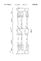
- FIG. 2 is a block diagram of the electrical and optical components employed in an optical data communications span
- FIG. 3 illustrates a portion of an optical network showing the role of an intermediate optical cross-connect switch
- FIG. 4 illustrates one approach to generating a modulated optical data signal containing high data rate modulation signal and subcarrier modulation signal components
- FIG. 5 is a block diagram of an optical communication network utilizing a subcarrier channel according to the present invention.
- FIG. 6A is a block diagram of a point of reception according to one embodiment of the present invention
- FIG. 6B is a block diagram of a point of reception with multiple summing amplifiers according to a further embodiment of the present invention
- FIG. 6C is a block diagram of a point of reception with a feedback controlled variable filter according to a further embodiment of the present invention.
- the present invention provides for the tracking of data signals in a communication network using low-level intensity-modulated subcarrier signals containing ancillary network data.
- This ancillary network management information can be communicated regardless of the quality or loss of the high data rate modulation signal. The manner in which this is accomplished is described in detail below.
- a subcarrier modulation signal can be generated, carried, and received in a "subcarrier channel.”
- the subcarrier channel is carried by all network equipment that generates, propagates, receives, and processes subcarrier modulation signals.
- a subcarrier modulation signal is a low frequency modulation signal, including but not limited to the range of approximately 10 KHz to 10 MHz.
- the subcarrier modulation signal includes ancillary network data that provides network management with the ability to monitor the status of a data signal traveling through the network. The present invention is not so limited, however, as any type of data can be carried in the subcarrier modulation signal.
- multi-wavelength modulated optical data signal refers to the optical data signal that is transported between WDM sites in an optical network.
- the multi-wavelength modulated optical data signal includes several individual "optical carrier” signals that have been multiplexed at a transmission site.
- Each "optical carrier” signal has a corresponding wavelength and can be generated by Line Terminating Equipment (LTEs) that include optical sources, such as laser diodes.
- LTEs Line Terminating Equipment
- each optical carrier signal includes a "high-bit-rate” (or “high data rate”) modulation signal that is the optical counterpart to a high data rate electrical signal, such as a SONET compliant STS-N signal, modulated at high frequency (e.g, 1 to 40 GHz).
- a high data rate electrical signal such as a SONET compliant STS-N signal
- the high data rate component of the optical carrier signal is also referred to as a "high data rate modulated optical data signal.”
- each optical carrier also includes the optical counterpart to the subcarrier modulation signal described above.
- one advantage of the present invention is that ancillary network data can be communicated regardless of the quality or loss of the high data rate modulation signal as long as the optical carrier persists. The manner in which this is accomplished is described in detail below.
- the present invention can be implemented in any optical communication network that utilizes subcarrier modulation signals to transport ancillary network data.
- FIG. 1 shows an example typical communications network 100 comprising sites 101-105 connected by links.
- Links are generally implemented using electrical cables, satellites, radio or microwave signals, or optical connections and can stretch for tens or hundreds of miles between sites.
- the communications system 100 carries data signals among the sites 101-105 to effectively interconnect data remote equipment 111-115, i.e., computers, remote terminals, servers, etc.
- One or more links 120 and 121 that connect two sites are collectively referred to as a span 130.
- These sites 101-105 normally contain at least one cross-connect switch (either electrical or optical) and are in constant communication with a central network management system facility 140 which monitors and/or controls the flow of traffic throughout the network.
- Example implementations of high data rate optical spans are depicted in FIGS. 2 and 3.
- a given site A is connected to another site B by a span comprising three optical fibers 230, 232, and 234.
- Two electrical data signals are presented at Site A via inputs 202 and 204. These signals are carried through the network span and recovered at Site B as electrical signal outputs 262 and 264, respectively.
- these data signals can be STS-48 synchronous data signals each bearing digital data at about 2.5 Gbps or the equivalent of 32 thousand telephone-quality voice channels.
- a signal enters a digital cross-connect switch (DCS) 210, and under normal conditions appears as an electrical signal.
- the signal enters optical Lightwave or Line Terminal Equipment (LTE) 220 shown to include an optical transmitter 221, such as a semiconductor laser.
- LTE Line Terminal Equipment
- Light emitted by the transmitter 221 is intensity-modulated by the electrical data signal that enters along connection 212 to deliver a modulated optical output signal over optical fiber 230.
- LTE 220 further includes wavelength division multiplexing (WDM) equipment, such as a wavelength division multiplexer, which allows for further bandwidth improvement by modulating different electrical data signals on distinct light wave carriers having different frequencies.
- WDM wavelength division multiplexing
- Optical systems using WDM require optical transmitters and receivers that operate at different light wave frequencies.
- the optical transmission line, such as optical fiber 230, connecting an optical transmitter and receiver, can propagate many light wave signals of different frequencies simultaneously.
- an optical signal can encounter a series of signal amplifying equipment, such as an optical amplifier (not shown) and/or an optical regenerator 237.
- Signal amplifying equipment are necessary to maintain signal strength over long fiber distances.
- Multiple optical amplifiers and/or regenerators can be spaced along a fiber link to increase range.
- the optical signal After traversing the length of fiber 230, the optical signal arrives at Site B and enters a receiver 241, such as a photodiode.
- the receiver 241 is shown to be a part of an LTE 240 that amplifies and conditions the signal to render a faithful electrical reproduction at output port 252 of the original electrical data signal provided at input 202.
- an electrical data signal presented at input 204 is transported by LTE 222, fiber 232, and LTE 242 to output port 254.
- LTE 240 contains WDM equipment that demultiplexes the multiple wavelength high data rate optical signal that travels over optical fiber 230.
- digital cross-connect switch DCS 260 connects port 252 to output port 262 to complete the end-to-end connection of input 202 to output 262.
- DCS 260 normally connects line 254 to output 264 to complete the end-to-end connection of input 204 to output 264.
- Span B-C connects site B to site C. Electrical DCS switches 210, 290 are provided at respective endpoint sites A, C. Traffic between sites A and C travels through an intermediate optical/electronic site B. Spans A-B and B-C interconnect the sites as shown. Thus, FIG. 2 illustrates the practice of performing optical-electrical-optical conversion at each site.
- controllers 280, 282, 284, coordinated with each other over a separate communications link 286, direct the switching action of DCSs 210, 260, 290 via control connections 275, 276, 277.
- Each controller is typically an imbedded microprocessor, computer, workstation, or other type of processor for controlling the switching of lightwave terminal equipment, digital cross-connect switches, and optical cross-connect switches.
- status messages can be sent to indicate, acknowledge, or confirm a link or node state such as an idle, active, inactive, or detected fault state.
- Any digital signaling protocol can be used including, but not limited to, X.25, Frame Relay, ATM, B-ISDN or Common Channel Signaling 7 protocols.
- controllers can communicate status messages using overhead bits or bytes within the data protocol that traverses the optical fibers. Restoration algorithms and protocols applied within the controllers to restore end-to-end connectivity in response to a fault detection are well known to those skilled in the art.
- FIG. 3 shows an example link where data signal switching is performed in the optical domain. Compared to optical-electronic switching as described with respect to FIG. 2, spans A-B and B-C are optically interconnected at site B.
- FIG. 3 shows that an entire set of LTEs and a DCS at site B have been replaced by an optical cross-connect switch (OCCS) 350 and several optical amplifiers 340-342 and 360-362.
- OCCS optical cross-connect switch
- Optical switch 350 is controlled by a controller or network management system in the same way as digital cross-connects 210, 260, 290.
- An electrical control signal (or an optical control signal) drives the optical switch to selectively form optical connections among various input and output ports facing working and protect optical fibers 330-334, 370-374.
- internal connections 352 and 354 within OCCS 350 optically couple respective working fibers 330, 332, 370, 372 in both spans A-B, B-C under normal network conditions as shown in FIG.3.
- the optical amplifiers 340-342, 360-362 intensify the lightwave signal and compensate for losses introduced by working fibers 330, 332, 370, 372 and OCCS 350.
- Optical switching introduces additional difficulties in network management. For example, conventional fault detection and isolation cannot be performed because signal integrity checks inherent in the electrical domain, such as cyclic redundancy check (CRC) and framing, are not performed in the optical domain.
- One method of introducing a checking or monitoring mechanism is to add a low level subcarrier to the optical carrier at a transmission site (e.g. site A in FIG. 3) and detect it at an optical switching node (e.g., site B, in FIG. 3).
- ancillary data is tagged onto the subcarrier modulation signal.
- the ancillary data can include network management information.
- a subcarrier modulation signal can contain important network status information (e.g., information about the integrity or performance of a data signal).
- the subcarrier modulation signal is modulated at or about 1 to 10 MHz and can be linearly added to an incident high data rate modulation signal, such as a SONET signal modulated at approximately 10 GHz.
- the ancillary network data can be recovered at any point along an optical network link.
- the recovered ancillary network data is useful for a myriad of network applications including tracing network timing references, cumulative link identification, wavelength remapping and re-use, telemetry and transmission performance evaluation, customer data payload identification, operational status indication, and/or other network management operations.
- FIG. 4 displays one approach to generating a modulated optical data signal containing high data rate modulation signal and subcarrier modulation signal components. See, “All Optical Network with Low Level Subcarrier for Ancillary Data," Ser. No. 08/673,651.
- a high data rate modulation signal 401 e.g a 1-10 GHz data signal
- a monitoring subcarrier modulation signal 402 is incident at a second input to combiner 410.
- Composite signal 415 representing the linear summation of signals 401 and 402, appears at the output of combiner 410.
- Composite signal 415 is used to intensity modulate laser diode 420 to produce an intensity modulated optical data signal 423 (also called an optical carrier signal), e.g., an Optical Carrier OC-192 signal.
- an intensity modulated optical data signal 423 also called an optical carrier signal
- Alternative means of externally modulating the gain of a signal transmitter or using coherent techniques known in the art may also be used to create an intensity modulated optical carrier signal that is modulated with a high data rate modulation signal and a superimposed low-level, subcarrier modulation signal 402.
- any type of high data rate modulated optical source can be used, such as an integrated-type of direct modulated laser or an externally modulated laser, depending upon the required performance, cost, and other known design considerations.
- the subcarrier modulation signal 402 has a lower frequency and/or amplitude than the high data rate modulation signal 401.
- the frequency of the superimposed subcarrier modulation signal 402 is several orders of magnitude less than that of the high data rate modulation signal 401.
- high data rate modulation signal 401 is on the order of 1 to 10 GHz, i.e. a SONET-compliant STS-48 digital signal (approx. 2.5 GHz) or an STS-192 signal (approx. 9.9 GHz)
- a subcarrier modulation signal 402 can range from 1 KHz to 10 MHz, depending on the response bandwidth of detection equipment used at a point of signal reception.
- the subcarrier modulation signal 402 has a fraction, i.e. one-tenth, of the amplitude of the high data rate modulation signal 401.
- These example frequencies and amplitudes are illustrative only, and not intended to limit the present invention.
- Other ranges of amplitudes and frequencies for the subcarrier modulation signal 402 and the high data rate modulation signal 401 can be selected.
- the modulated optical signal is eventually transported over fiber link 424 to site B (such as shown in either FIGS. 2 or 3).
- a high signal quality subcarrier channel is managed in a WDM network.
- FIG. 5 displays the present invention in an example WDM network implementation.
- a high data rate modulation signal 501a is presented at site A at an input 505 to a WDM LTE 520, which includes a series of optical transmitters 510a-510d.
- Other high data rate modulation signals 501b-501d are presented at further respective inputs 506-508 to LTE 520.
- High data rate modulation signals 501a-501d can originate from path terminating equipment located at various local user sites or enter LTE 520 directly from an adjacent digital cross-connect switch (not shown).
- LTE 520 may also comprise signal receiving equipment. For simplicity, only transmitting equipment is shown at LTE 520 in FIG. 5.
- each high data rate modulation signal 501a-501d comprises a 1-10 GHz data signal, such as a SONET rate STS-N electrical signal.
- These high data rate modulation signals 501a-501d are used to modulate laser diodes 510a-510d, which convert the electrical data signals into corresponding optical carrier signals, referred to as SONET OC-N type signals.
- optical transmitters 510a-510d are directly modulated semiconductor laser diodes, which can either operate at a fixed wavelength or operate as tunable devices. Other types of optical transmitters and modulators can be used.
- the high data rate modulation signals 501a-501d are used to modulate drivers 511a-511d, which drive laser diodes 510a-501d, respectively, to create modulated optical data signals.
- a tunable optical transmitter can be used to transmit modulated optical data signals.
- This tunable source can be either a tunable laser (such as a semiconductor diode laser) or a fixed source coupled to a frequency translator. See, commonly owned applications Ser. Nos. 08/577,663 and 08/672,808, incorporated herein by reference above.
- An electrical subcarrier modulation signal 502 containing ancillary network information is generated by subcarrier modulation signal generator 504.
- subcarrier modulation signal 502 can be used in a communication network to convey network information to and from the network management system 580 at various nodes throughout the communication network.
- Subcarrier modulation signal 502 has a lower amplitude than the high data rate modulation signal (approximately one-tenth of the high data rate modulation signal amplitude).
- subcarrier modulation signal 502 has a lower frequency (10 KHz-10 MHz) than the high data rate modulation signal (1-10 GHz).
- the same subcarrier modulation signal 502 is applied to the multiple high data rate modulation signals which will propagate along a common optical path.
- subcarrier signal generator 504 simultaneously presents subcarrier modulation signal 502 at each laser diode driver 511a-511d via electrical conduit 509.
- Subcarrier modulation signal 502 and high data rate modulation signal 501a form the bias current driving laser diode 510a and are thus superimposed onto the modulated optical data signal that is emitted along fiber 512.
- a method utilizing a signal combiner can be used to create modulated optical data signals, which contain high data rate modulation signal 501a-501d and subcarrier modulation signal 502 components.
- each laser diode 510a-510d at LTE 520 operates at a different optical wavelength.
- laser diode 510a generates an optical carrier signal with an operating wavelength ⁇ 1 .
- Laser diodes 510b-510d generate optical carrier signals of wavelengths ⁇ 2 - ⁇ 4 , respectively.
- These multiple wavelength optical signals propagate along respective fibers 512-515 and enter optical multiplexer 517.
- Optical multiplexer 517 forms a single, multiplexed, modulated optical data signal 503.
- Multiplexed, modulated optical data signal 503 propagates along outbound fiber link 530 to some other node located in the communication network.
- Multiplexer 517 may be a star coupler, grating-type multiplexer, or other wavelength combining device that is well known in the art.
- Modulated optical data signal 503 has four wavelength components ( ⁇ 1 - ⁇ 4 ) in this example. In general, any number of separate wavelength signals can be contained in modulated optical data signal 503, depending on the type of WDM equipment utilized at LTE 520.
- the WDM modulated optical data signal 503 After traveling a given distance over optical fiber 530, the WDM modulated optical data signal 503 encounters a signal reception point.
- the signal reception point can be, for example, a LTE receiver, such as LTE 540, or, in the case of a long distance fiber link, some type of section terminating equipment (STE), such as optical regenerator 535, which is utilized to maintain signal strength.
- the modulated optical data signal can be de-multiplexed in order to separate out the various wavelength components of the carrier signal, and the ancillary network information can be simultaneously received with an improved SNR within subcarrier channel 525.
- subcarrier channel 525 is supported by subcarrier modulation signal generating and receiving equipment located in the communication network.
- FIG. 5 displays a signal reception point at site B, wherein LTE 540 can demultiplex the multiple wavelength components of modulated optical data signal 503 through the use of optical signal de-multiplexer 542.
- Optical signal de-multiplexer 542 can include a single block WDM grating device, as shown here in FIG. 5, or an optical signal splitter and a series of optical filters, as shown in FIG. 6A (described further below).
- a series of photodetectors 541a-541d respectively detect the separate wavelength components of the de-multiplexed optical signal and generate electrical signals 542a-542d representative of the respective optical signals.
- a composite subcarrier modulation signal with an improved SNR is recovered in subcarrier channel 525 by summing amplifier 560.
- Summing amplifier 560 sums the subcarrier modulation signals contained in each separate electrical representative. Portions of the electrical signals 542a-542d are tapped off by electrical conduits 547 into a summing amplifier 560.
- the input impedance of summing amplifier 550 is chosen to be high enough to prevent the loss of signal strength of electrical signals 542a-542d, which continue on to channel outputs 552-555.
- summing amplifier 560 can be any known, slow-response time, multi-channel electrical signal amplifier. See, The Art of Electronics, by P. Horowitz and W. Hill, Cambridge University Press, p. 185 (1994), incorporated herein by reference. Summing amplifier 560 functions similar to an Amplitude Modulation (AM) detector. the high frequency component of the electrical representative signals 542a-542d (i.e., the SONET rate data signals corresponding to high data rate modulation signals 501a-501d) are of such a high frequency as to be outside of the response band of summing amplifier 560.
- AM Amplitude Modulation
- the electrical outputs of all the optical detectors are summed to take advantage of the multiple reception channels.
- the subcarrier components will add, whereas the noise will tend to cancel, yielding an improved SNR within the subcarrier channel 525.
- This effect can also be employed to allow for lower modulation levels of the subcarrier modulation signals while preserving the same SNR.
- the present invention can be used to assure robust transmission of subcarrier data along a WDM path even if some of the optical carriers fail.
- Electrical signals 542a-542d are available at channel outputs 552-555. These signals 542a-542d travel to network equipment capable of demultiplexing the high data rate SONET rate signal to its constituent DS-3 signal. Alternatively, this point of reception can be located at a node that will regroom the content of the optical signals and switch them onto different outgoing links. For example, channel outputs 552 and 553 can be switched to north-bound links and channel outputs 554 and 555 can be switched to east-bound links. Thereafter, these high data rate modulation signals 542a-542d travel to other outbound LTEs for remodulation before they are sent out in their intended directions.
- STS-N electrical signals are available at channel outputs 552-555.
- the output of summing amplifier 560 is referred to as a composite subcarrier modulation signal 561 which travels to a subcarrier receiver 562.
- Subcarrier generator, summing amplifier 560, and subcarrier receiver 562 support subcarrier channel 525.
- Subcarrier receiver 562 in turn, can send composite subcarrier modulation signal 561 to another subcarrier modulation signal generator (not shown) located in subcarrier channel 525.
- subcarrier receiver 562 provides an access point for network management system 580 to monitor the status of subcarrier channel 525.
- subcarrier channel 525 provides the communication network with an adjunct, indication channel that contains, for example, line code information, modulation scheme information, and/or signal rate information.
- composite subcarrier modulation signal 561 can provide network management with fault detection information, such as a fiber break, equipment failure, or signal status information.
- the point of reception can also occur at an optical regenerator, such as optical regenerator 535.
- the present invention is compatible with a communication network using optical cross-connect switches (OCCSs), such as OCCS 350 shown in FIG. 3.
- OCCSs optical cross-connect switches
- OCCS 350 leaves all wavelengths of a WDM modulated optical data signal intact (i.e., it does not convert the WDM modulated optical data signal back into the electrical domain). Therefore, the subcarrier modulation signal component of the WDM modulated optical data signal, such as subcarrier modulation signal 502, need not be regenerated at an optical switching site.
- FIG. 6A schematically illustrates this alternate embodiment of the present invention.
- a modulated optical data signal 603 is generated and propagated along a fiber link 630 by WDM equipment in a similar manner as described above in connection with FIG. 5.
- Modulated optical data signal 603 comprises both high data rate and subcarrier modulation signal components, such as signals 501a -501d and signal 502 from FIG. 5.
- optical signal splitter 610 separates the incoming modulated optical data signal into five separate signals, corresponding to the number of multiple wavelength carriers, which in this example consists of five different wavelength carriers ( ⁇ 1 - ⁇ 5 ).
- Optical signal splitter 610 can be any type of known optical splitter.
- Optical filters 615a-615e operate as band-pass filters and pass respective wavelength components of the split optical signal along optical fibers 631a-631e to a series of photodetectors 641a-641e.
- optical filter 615a passes only the ⁇ 1 component of the WDM modulated optical data signal onto photodetector 641a
- optical filter 615b passes only the ⁇ 2 component of the WDM modulated optical data signal onto photodetector 641b, etc.
- Photodetectors 641a-641e generate electrical signals corresponding to the separate wavelength components of the WDM modulated optical data signal in a similar manner as described above in connection with FIG. 5.
- the subcarrier components of the electrical signals emerging from photodetectors 641a-641e are tapped-off into the slow-response summing amplifier 660 of the subcarrier channel 625.
- a high impedance amplifier can be used for amplifier 660 in order to avoid reducing the signal strength of the electrical signals.
- the electrical signals are amplified by a series of electrical signal amplifiers 651a-651e and are sent to channel outputs 652-656, respectively.
- FIG. 6B schematically illustrates this alternate embodiment of the present invention.
- the low frequency components of the electrical signals generated by photodetectors 641a-641e can be directed into a multi-channel switch 665.
- Switch 665 can be activated by network management (such as network management system 580 in FIG. 5) to switch a portion or all of the electrical signals along electrical conduits 667 towards summing amplifier 660.
- the remaining signals can be directed along electrical conduits 677 towards a second summing amplifier 670 also located at this point of reception.
- Summing amplifiers 660 and 670 generate composite subcarrier signals 661 and 671, respectively.
- Composite subcarrier signals 661 and 671 can be used for a variety of network applications, as explained above. For example, when this point of reception according to the present invention is located at a switching node, composite subcarrier signal 661 can be used as a rider on modulated optical data signals traveling in the eastbound direction. Similarly, composite subcarrier signal 671 can be used as a rider on modulated optical data signals traveling in the southbound direction.
- the present invention provides a switching arrangement that facilitates recovery from network failures by regrouping the photodetector signals into additional summing amplifiers.
- this embodiment of the present invention allows flexible subcarrier modulation signal assignments.
- the present invention can further improve the SNR of the subcarrier channel by optimizing the composite subcarrier signal.
- This optimization is achieved by implementing a controller-based filtering system illustrated in FIG. 6C.
- the signals from photodetectors 641a-641e are respectively sent along conduits 681a-681e to summing amplifier 660.
- the electrical signals are sent to a variable filter 682 that includes a series of variable filters corresponding to the number of photodetectors.
- variable filter 682 is placed on the input side of summing amplifier 660 to initially filter the electrical signal representatives of the subcarrier signal.
- a feedback signal is utilized to fine tune variable filter 682.
- a small portion of composite subcarrier signal 661 is tapped off along conduit 684 and sent to a detector 685.
- Detector 685 gauges the purity of composite subcarrier signal 661 to maximize the SNR.
- Detector 685 sends a control signal (not shown) to controller 686.
- Controller 686 adjusts the individual filters of variable filter 682 to optimize composite subcarrier signal 661.
- Detector 685, controller 686, and variable filter 682 can each comprise conventional electronic devices well known in the art.
- the present invention offers several advantages to a communications network environment.
- use of a subcarrier modulation signal containing ancillary network data reduces invasiveness into the high-rate signal.
- the composite subcarrier modulation signal such as signal 561 from FIG. 5, has a much improved SNR over a single subcarrier modulation signal since the summing amplifier 560 acts to cancel out the low frequency line noise picked up in a modulated optical data signal that has been propagated over a long distance.
- the presence of a stronger composite subcarrier modulation signal in the subcarrier channel provides for faster error detection.
- the composite subcarrier modulation signal provides for a fail-safe conduction of subcarrier data: if the signal strength of single subcarrier modulation signal component of an optical carrier is somehow reduced over a long distance fiber link, the summation of the other subcarrier components will still result in an adequate composite subcarrier modulation signal.
- the present invention enables all-optical fault detection and subcarrier network communications for wavelength routing, restoration, and quality monitoring in a communication network.
Abstract
Description
Claims (29)
Priority Applications (3)
| Application Number | Priority Date | Filing Date | Title |
|---|---|---|---|
| US08/941,546 US5995256A (en) | 1997-09-30 | 1997-09-30 | Method and system for managing optical subcarrier reception |
| AU10645/99A AU1064599A (en) | 1997-09-30 | 1998-09-29 | Method and system for managing optical subcarrier reception |
| PCT/US1998/020604 WO1999017484A1 (en) | 1997-09-30 | 1998-09-29 | Method and system for managing optical subcarrier reception |
Applications Claiming Priority (1)
| Application Number | Priority Date | Filing Date | Title |
|---|---|---|---|
| US08/941,546 US5995256A (en) | 1997-09-30 | 1997-09-30 | Method and system for managing optical subcarrier reception |
Publications (1)
| Publication Number | Publication Date |
|---|---|
| US5995256A true US5995256A (en) | 1999-11-30 |
Family
ID=25476672
Family Applications (1)
| Application Number | Title | Priority Date | Filing Date |
|---|---|---|---|
| US08/941,546 Expired - Lifetime US5995256A (en) | 1997-09-30 | 1997-09-30 | Method and system for managing optical subcarrier reception |
Country Status (3)
| Country | Link |
|---|---|
| US (1) | US5995256A (en) |
| AU (1) | AU1064599A (en) |
| WO (1) | WO1999017484A1 (en) |
Cited By (67)
| Publication number | Priority date | Publication date | Assignee | Title |
|---|---|---|---|---|
| US6236480B1 (en) * | 1998-05-01 | 2001-05-22 | Dogan A. Atlas | System and method for reducing Raman cross-talk in a DWDM transport system |
| US6271944B1 (en) * | 1999-06-30 | 2001-08-07 | Philips Electronics North America Corp. | Laser wavelength control in an optical communication system |
| US20020005967A1 (en) * | 2000-07-12 | 2002-01-17 | Oki Electric Industry Co., Ltd. | Wavelength division multiplex transmission system |
| US20020118413A1 (en) * | 2001-02-28 | 2002-08-29 | Naoshi Yamada | Media converter with integrated local information transmission function and fault alarm signal transmission system |
| US20020131107A1 (en) * | 2001-03-16 | 2002-09-19 | Hait John N. | Hyper-dense photonic signal apparatus |
| US20020141018A1 (en) * | 2001-01-30 | 2002-10-03 | Gee-Kung Chang | Optical layer multicasting using a single sub-carrier header and a multicast switch with active header insertion |
| US20020145778A1 (en) * | 2001-03-16 | 2002-10-10 | Photuris, Inc. | Wavelength division multiplexed optical communication system having a reconfigurable optical switch and a tunable backup laser transmitter |
| US20020145779A1 (en) * | 2001-03-16 | 2002-10-10 | Strasser Thomas Andrew | Method and apparatus for interconnecting a plurality of optical transducers with a wavelength division multiplexed optical switch |
| US6469812B2 (en) * | 1998-12-18 | 2002-10-22 | Worldcom, Inc. | Method and system for identifying undesired products of non-linear optical mixing |
| US20020159113A1 (en) * | 2001-04-27 | 2002-10-31 | Nec Corporation | Alarm control system and method |
| US6513092B1 (en) | 2000-04-18 | 2003-01-28 | Nec Eluminant Technologies, Inc. | 1:N protection switching architecture for common processing units |
| US6519062B1 (en) | 2000-02-29 | 2003-02-11 | The Regents Of The University Of California | Ultra-low latency multi-protocol optical routers for the next generation internet |
| US6522435B1 (en) * | 1998-07-17 | 2003-02-18 | The Regents Of The University Of California | High-throughput, low-latency next generation internet networks using optical label switching and high-speed optical header generation, detection and reinsertion |
| US6525850B1 (en) * | 1998-07-17 | 2003-02-25 | The Regents Of The University Of California | High-throughput, low-latency next generation internet networks using optical label switching and high-speed optical header generation, detection and reinsertion |
| US6545781B1 (en) * | 1998-07-17 | 2003-04-08 | The Regents Of The University Of California | High-throughput, low-latency next generation internet networks using optical label switching and high-speed optical header generation, detection and reinsertion |
| US6574016B1 (en) * | 1998-11-25 | 2003-06-03 | Nortel Networks Limited | Method and apparatus for ancillary data in a wavelength division multiplexed system |
| US6580537B1 (en) * | 1998-07-17 | 2003-06-17 | Regents Of The University Of California, The | High-throughput, low-latency next generation internet networks using optical label switching and high-speed optical header generation, detection and reinsertion |
| US6724996B1 (en) * | 1999-12-29 | 2004-04-20 | Lucent Technologies Inc. | Apparatus and method for providing optical channel overhead in optical transport networks |
| US6754450B2 (en) | 2001-01-30 | 2004-06-22 | The Regents Of The University Of California | Optical layer multicasting using a single sub-carrier header with active header detection, deletion, and new header insertion via opto-electrical processing |
| US6757497B2 (en) | 2001-01-30 | 2004-06-29 | The Regents Of The University Of California | Optical layer multicasting using a single sub-carrier header and a multicast switch with active header insertion via reflective single sideband optical processing |
| US6757496B2 (en) | 2001-01-30 | 2004-06-29 | The Regents Of The University Of California | Optical layer multicasting using a single sub-carrier header and an optical multicasting switch |
| US6768871B2 (en) | 2001-01-30 | 2004-07-27 | The Regents Of The University Of California | Optical layer multicasting using a multicast switch to effect survivability and security |
| US6795607B1 (en) * | 2000-10-11 | 2004-09-21 | Ciena Corporation | Use of tunable laser for optical performance monitoring in WDM system |
| US6813276B2 (en) | 2001-01-30 | 2004-11-02 | The Regents Of The University Of California | Optical layer multicasting using a single sub-carrier header with active header detection, deletion, and re-insertion via a circulating optical path |
| US6819666B2 (en) | 2001-01-30 | 2004-11-16 | The Regents Of The University Of California | Optical layer multicasting using multiple sub-carrier headers with header detection, deletion, and insertion via reflective single sideband optical processing |
| US6850707B1 (en) | 2001-01-30 | 2005-02-01 | The Regents Of The University Of California | Secure optical layer multicasting to effect survivability |
| US6850515B2 (en) | 2001-01-30 | 2005-02-01 | The Regents Of The University Of California | Optical layer multicasting using a single sub-carrier header and a multicast switch with active header insertion via light circulation |
| US20050041969A1 (en) * | 2003-08-19 | 2005-02-24 | Alcatel | Dynamic control of power loss in an optical fiber by contrapropagation of a supervisory channel |
| US6873797B2 (en) | 2001-01-30 | 2005-03-29 | The Regents Of The University Of California | Optical layer multicasting |
| US20050201752A1 (en) * | 2004-03-12 | 2005-09-15 | Futurewei Technologies, Inc. | System and method for subcarrier modulation as supervisory channel |
| US20050201753A1 (en) * | 2004-03-12 | 2005-09-15 | Futurewei Technologies, Inc. | System and method for subcarrier modulation in ISM band as supervisory channel |
| US6950865B1 (en) | 2001-03-26 | 2005-09-27 | Cisco Technology, Inc. | Network audit tool |
| US20050254825A1 (en) * | 2004-05-12 | 2005-11-17 | Futurewei Technologies, Inc. | System and method for automatic chromatic dispersion compensation |
| US6968130B1 (en) * | 1999-09-07 | 2005-11-22 | Nokia Corporation | System and method for fully utilizing available optical transmission spectrum in optical networks |
| WO2006001903A2 (en) * | 2004-06-09 | 2006-01-05 | Comcast Cable-Holdings, Llc | System and method for capacity allocation in hfc catv networks |
| US20060140631A1 (en) * | 2004-12-29 | 2006-06-29 | Brolin Stephen J | Shared multi-lambda source for WDM PON |
| US7079780B1 (en) * | 1999-05-28 | 2006-07-18 | Northrop Grumman Corporation | Linearized optical link using a single Mach-Zehnder modulator and two optical carriers |
| US7103149B1 (en) | 2001-04-06 | 2006-09-05 | Cisco Technologu, Inc. | Optical transport concentrator audit system and method |
| US7130537B1 (en) * | 2000-08-25 | 2006-10-31 | Alcatel | Safety shutdown system for a WDM fiber optic communications network |
| US20060269289A1 (en) * | 2003-06-04 | 2006-11-30 | Ciphergen Biosystems, Inc. | Communications system |
| US7224898B1 (en) * | 2001-05-21 | 2007-05-29 | Cisco Technology, Inc. | Carrier class DWDM optical network audit tool |
| US20080131120A1 (en) * | 2006-12-05 | 2008-06-05 | Nec Laboratories America, Inc. | Wavelength division multiplexing passive optical network architecture with source-free optical network units |
| US20080193127A1 (en) * | 2007-02-09 | 2008-08-14 | Ciena Corporation | System and method for a channel guard in a reconfigurable optical add-drop multiplexer |
| US20080205900A1 (en) * | 2007-02-28 | 2008-08-28 | Finisar Corporation | Status link for multi-channel optical communication systems |
| US20080267620A1 (en) * | 2007-04-30 | 2008-10-30 | Finisar Corporation | Eye safety and interoperability of active cable devices |
| US20090060520A1 (en) * | 2007-02-28 | 2009-03-05 | Finisar Corporation | Redundancy and interoperability in multi-channel optoelectronic devices |
| US20120269510A1 (en) * | 2010-12-17 | 2012-10-25 | Board Of Regents, The University Of Texas System | Digital subcarrier optical network utilizing digital subcarrier cross-connects with increased energy efficiency |
| US20130077977A1 (en) * | 2010-03-30 | 2013-03-28 | France Telecom | Method and module for processing a request for transmitting a radio signal in an ROF system |
| US20130195452A1 (en) * | 2010-12-17 | 2013-08-01 | Rongqing Hui | Digital subcarrier cross-connect switching |
| US20140376909A1 (en) * | 2013-06-19 | 2014-12-25 | Finisar Corporation | Optical Channel Monitor With High Resolution Capability |
| US20160285548A1 (en) * | 2013-12-13 | 2016-09-29 | Fujitsu Limited | Multi-carrier optical transmission system, optical transmitter, and optical receiver |
| US9843391B2 (en) * | 2006-04-28 | 2017-12-12 | Commscope Technologies Llc | Systems and methods of optical path protection for distributed antenna systems |
| US10014955B1 (en) * | 2015-04-24 | 2018-07-03 | Vencore Labs, Inc. | Signal processing circuit with optical local oscillator signal |
| US20180248626A1 (en) * | 2015-08-24 | 2018-08-30 | Telefonaktiebolaget Lm Ericsson (Publ) | Control of an Optical Transmitter in a Radio Over Fibre System |
| WO2019195244A1 (en) * | 2018-04-02 | 2019-10-10 | Rensselaer Polytechnic Institute | Cross-connect switch architecture |
| US10594399B2 (en) * | 2017-05-05 | 2020-03-17 | Cisco Technology, Inc. | Downstream node setup |
| US10993003B2 (en) | 2019-02-05 | 2021-04-27 | Cox Communications, Inc. | Forty channel optical communications module link extender related systems and methods |
| US10999658B2 (en) | 2019-09-12 | 2021-05-04 | Cox Communications, Inc. | Optical communications module link extender backhaul systems and methods |
| US10999656B2 (en) | 2017-01-20 | 2021-05-04 | Cox Communications, Inc. | Coherent gigabit ethernet and passive optical network coexistence in optical communications module link extender related systems and methods |
| US11063685B2 (en) | 2017-01-20 | 2021-07-13 | Cox Communications, Inc. | Optical communications module related systems and methods |
| US11146350B1 (en) | 2020-11-17 | 2021-10-12 | Cox Communications, Inc. | C and L band optical communications module link extender, and related systems and methods |
| US11271670B1 (en) | 2020-11-17 | 2022-03-08 | Cox Communications, Inc. | C and L band optical communications module link extender, and related systems and methods |
| US11317177B2 (en) * | 2020-03-10 | 2022-04-26 | Cox Communications, Inc. | Optical communications module link extender, and related systems and methods |
| US11323788B1 (en) | 2021-02-12 | 2022-05-03 | Cox Communications, Inc. | Amplification module |
| US11502770B2 (en) | 2017-01-20 | 2022-11-15 | Cox Communications, Inc. | Optical communications module link extender, and related systems and methods |
| US11523193B2 (en) | 2021-02-12 | 2022-12-06 | Cox Communications, Inc. | Optical communications module link extender including ethernet and PON amplification |
| US11689287B2 (en) | 2021-02-12 | 2023-06-27 | Cox Communications, Inc. | Optical communications module link extender including ethernet and PON amplification |
Citations (2)
| Publication number | Priority date | Publication date | Assignee | Title |
|---|---|---|---|---|
| US5726783A (en) * | 1989-12-08 | 1998-03-10 | British Telecommunications Public Limited Company | Optical fibre communication system |
| US5739934A (en) * | 1995-08-09 | 1998-04-14 | Nec Corporation | Wavelength division multiplexing lightwave transmission system |
-
1997
- 1997-09-30 US US08/941,546 patent/US5995256A/en not_active Expired - Lifetime
-
1998
- 1998-09-29 WO PCT/US1998/020604 patent/WO1999017484A1/en active Application Filing
- 1998-09-29 AU AU10645/99A patent/AU1064599A/en not_active Abandoned
Patent Citations (2)
| Publication number | Priority date | Publication date | Assignee | Title |
|---|---|---|---|---|
| US5726783A (en) * | 1989-12-08 | 1998-03-10 | British Telecommunications Public Limited Company | Optical fibre communication system |
| US5739934A (en) * | 1995-08-09 | 1998-04-14 | Nec Corporation | Wavelength division multiplexing lightwave transmission system |
Cited By (106)
| Publication number | Priority date | Publication date | Assignee | Title |
|---|---|---|---|---|
| US6236480B1 (en) * | 1998-05-01 | 2001-05-22 | Dogan A. Atlas | System and method for reducing Raman cross-talk in a DWDM transport system |
| US6525850B1 (en) * | 1998-07-17 | 2003-02-25 | The Regents Of The University Of California | High-throughput, low-latency next generation internet networks using optical label switching and high-speed optical header generation, detection and reinsertion |
| US6522435B1 (en) * | 1998-07-17 | 2003-02-18 | The Regents Of The University Of California | High-throughput, low-latency next generation internet networks using optical label switching and high-speed optical header generation, detection and reinsertion |
| US6674558B1 (en) * | 1998-07-17 | 2004-01-06 | The Regents Of The University Of California | High-throughput, low-latency next generation internet networks using optical label switching and high-speed optical header generation, detection and reinsertion |
| US6545781B1 (en) * | 1998-07-17 | 2003-04-08 | The Regents Of The University Of California | High-throughput, low-latency next generation internet networks using optical label switching and high-speed optical header generation, detection and reinsertion |
| US6525851B2 (en) | 1998-07-17 | 2003-02-25 | The Regents Of The University Of California | High-throughput, low-latency next generation internet networks using optical label switching and high-speed optical header generation, detection and reinsertion |
| US6657757B1 (en) * | 1998-07-17 | 2003-12-02 | The Regents Of The University Of California | High-throughput low-latency next generation internet network using optical label switching and high-speed optical header generation detection and reinsertion |
| US6580537B1 (en) * | 1998-07-17 | 2003-06-17 | Regents Of The University Of California, The | High-throughput, low-latency next generation internet networks using optical label switching and high-speed optical header generation, detection and reinsertion |
| US6574016B1 (en) * | 1998-11-25 | 2003-06-03 | Nortel Networks Limited | Method and apparatus for ancillary data in a wavelength division multiplexed system |
| US6469812B2 (en) * | 1998-12-18 | 2002-10-22 | Worldcom, Inc. | Method and system for identifying undesired products of non-linear optical mixing |
| US7079780B1 (en) * | 1999-05-28 | 2006-07-18 | Northrop Grumman Corporation | Linearized optical link using a single Mach-Zehnder modulator and two optical carriers |
| US6271944B1 (en) * | 1999-06-30 | 2001-08-07 | Philips Electronics North America Corp. | Laser wavelength control in an optical communication system |
| US6968130B1 (en) * | 1999-09-07 | 2005-11-22 | Nokia Corporation | System and method for fully utilizing available optical transmission spectrum in optical networks |
| US6724996B1 (en) * | 1999-12-29 | 2004-04-20 | Lucent Technologies Inc. | Apparatus and method for providing optical channel overhead in optical transport networks |
| US6925257B2 (en) | 2000-02-29 | 2005-08-02 | The Regents Of The University Of California | Ultra-low latency multi-protocol optical routers for the next generation internet |
| US6519062B1 (en) | 2000-02-29 | 2003-02-11 | The Regents Of The University Of California | Ultra-low latency multi-protocol optical routers for the next generation internet |
| US20030030866A1 (en) * | 2000-02-29 | 2003-02-13 | Sung-Joo Yoo | Ultra-low latency multi-protocol optical routers for the next generation internet |
| US6513092B1 (en) | 2000-04-18 | 2003-01-28 | Nec Eluminant Technologies, Inc. | 1:N protection switching architecture for common processing units |
| US20020005967A1 (en) * | 2000-07-12 | 2002-01-17 | Oki Electric Industry Co., Ltd. | Wavelength division multiplex transmission system |
| US7139482B2 (en) * | 2000-07-12 | 2006-11-21 | Oki Electric Industry Co., Ltd. | Wavelength division multiplex transmission system |
| US7130537B1 (en) * | 2000-08-25 | 2006-10-31 | Alcatel | Safety shutdown system for a WDM fiber optic communications network |
| US6795607B1 (en) * | 2000-10-11 | 2004-09-21 | Ciena Corporation | Use of tunable laser for optical performance monitoring in WDM system |
| US6757496B2 (en) | 2001-01-30 | 2004-06-29 | The Regents Of The University Of California | Optical layer multicasting using a single sub-carrier header and an optical multicasting switch |
| US6819666B2 (en) | 2001-01-30 | 2004-11-16 | The Regents Of The University Of California | Optical layer multicasting using multiple sub-carrier headers with header detection, deletion, and insertion via reflective single sideband optical processing |
| US6757497B2 (en) | 2001-01-30 | 2004-06-29 | The Regents Of The University Of California | Optical layer multicasting using a single sub-carrier header and a multicast switch with active header insertion via reflective single sideband optical processing |
| US6934472B2 (en) * | 2001-01-30 | 2005-08-23 | The Regents Of The University Of California | Optical layer multicasting using a single sub-carrier header and a multicast switch with active header insertion |
| US6768871B2 (en) | 2001-01-30 | 2004-07-27 | The Regents Of The University Of California | Optical layer multicasting using a multicast switch to effect survivability and security |
| US20020141018A1 (en) * | 2001-01-30 | 2002-10-03 | Gee-Kung Chang | Optical layer multicasting using a single sub-carrier header and a multicast switch with active header insertion |
| US6813276B2 (en) | 2001-01-30 | 2004-11-02 | The Regents Of The University Of California | Optical layer multicasting using a single sub-carrier header with active header detection, deletion, and re-insertion via a circulating optical path |
| US6754450B2 (en) | 2001-01-30 | 2004-06-22 | The Regents Of The University Of California | Optical layer multicasting using a single sub-carrier header with active header detection, deletion, and new header insertion via opto-electrical processing |
| US6850707B1 (en) | 2001-01-30 | 2005-02-01 | The Regents Of The University Of California | Secure optical layer multicasting to effect survivability |
| US6850515B2 (en) | 2001-01-30 | 2005-02-01 | The Regents Of The University Of California | Optical layer multicasting using a single sub-carrier header and a multicast switch with active header insertion via light circulation |
| US6873797B2 (en) | 2001-01-30 | 2005-03-29 | The Regents Of The University Of California | Optical layer multicasting |
| EP1246406A2 (en) * | 2001-02-28 | 2002-10-02 | Fujikura Ltd. | Media converter with integrated local information transmission function and fault alarm signal transmission system |
| US7170859B2 (en) | 2001-02-28 | 2007-01-30 | Fujikura Ltd. | Media converter with integrated local information transmission function and fault alarm signal transmission system |
| EP1246406A3 (en) * | 2001-02-28 | 2005-08-10 | Fujikura Ltd. | Media converter with integrated local information transmission function and fault alarm signal transmission system |
| US20020118413A1 (en) * | 2001-02-28 | 2002-08-29 | Naoshi Yamada | Media converter with integrated local information transmission function and fault alarm signal transmission system |
| US20100098406A1 (en) * | 2001-03-16 | 2010-04-22 | Meriton Networks Us Inc. | Method and apparatus for interconnecting a plurality of optical transducers with a wavelength division multiplexed optical switch |
| US7620323B2 (en) * | 2001-03-16 | 2009-11-17 | Meriton Networks Us Inc. | Method and apparatus for interconnecting a plurality of optical transducers with a wavelength division multiplexed optical switch |
| US20020145778A1 (en) * | 2001-03-16 | 2002-10-10 | Photuris, Inc. | Wavelength division multiplexed optical communication system having a reconfigurable optical switch and a tunable backup laser transmitter |
| US7599619B2 (en) * | 2001-03-16 | 2009-10-06 | Meriton Networks Us Inc. | Wavelength division multiplexed optical communication system having a reconfigurable optical switch and a tunable backup laser transmitter |
| US20100021162A1 (en) * | 2001-03-16 | 2010-01-28 | Meriton Networks Us Inc. | Wavelength division multiplexed optical communication system having a reconfigurable optical switch and a tunable backup laser transmitter |
| US20020145779A1 (en) * | 2001-03-16 | 2002-10-10 | Strasser Thomas Andrew | Method and apparatus for interconnecting a plurality of optical transducers with a wavelength division multiplexed optical switch |
| US20020131107A1 (en) * | 2001-03-16 | 2002-09-19 | Hait John N. | Hyper-dense photonic signal apparatus |
| US6950865B1 (en) | 2001-03-26 | 2005-09-27 | Cisco Technology, Inc. | Network audit tool |
| US7103149B1 (en) | 2001-04-06 | 2006-09-05 | Cisco Technologu, Inc. | Optical transport concentrator audit system and method |
| US20020159113A1 (en) * | 2001-04-27 | 2002-10-31 | Nec Corporation | Alarm control system and method |
| US7068931B2 (en) * | 2001-04-27 | 2006-06-27 | Nec Corporation | Alarm control system and method |
| US7224898B1 (en) * | 2001-05-21 | 2007-05-29 | Cisco Technology, Inc. | Carrier class DWDM optical network audit tool |
| US7574142B2 (en) * | 2003-06-04 | 2009-08-11 | Ericsson Ab | Communications system |
| US20060269289A1 (en) * | 2003-06-04 | 2006-11-30 | Ciphergen Biosystems, Inc. | Communications system |
| US20050041969A1 (en) * | 2003-08-19 | 2005-02-24 | Alcatel | Dynamic control of power loss in an optical fiber by contrapropagation of a supervisory channel |
| US7274872B2 (en) | 2004-03-12 | 2007-09-25 | Futurewei Technologies, Inc. | System and method for subcarrier modulation as supervisory channel |
| US20050201753A1 (en) * | 2004-03-12 | 2005-09-15 | Futurewei Technologies, Inc. | System and method for subcarrier modulation in ISM band as supervisory channel |
| US20050201752A1 (en) * | 2004-03-12 | 2005-09-15 | Futurewei Technologies, Inc. | System and method for subcarrier modulation as supervisory channel |
| US7509047B2 (en) | 2004-03-12 | 2009-03-24 | Futurewei Technologies, Inc. | System and method for subcarrier modulation in ISM band as supervisory channel |
| US20050254825A1 (en) * | 2004-05-12 | 2005-11-17 | Futurewei Technologies, Inc. | System and method for automatic chromatic dispersion compensation |
| US7542685B2 (en) * | 2004-05-12 | 2009-06-02 | Futurewei Technologies, Inc. | System and method for automatic chromatic dispersion compensation |
| WO2006001903A2 (en) * | 2004-06-09 | 2006-01-05 | Comcast Cable-Holdings, Llc | System and method for capacity allocation in hfc catv networks |
| WO2006001903A3 (en) * | 2004-06-09 | 2007-04-26 | Comcast Cable Holdings Llc | System and method for capacity allocation in hfc catv networks |
| US7630638B2 (en) * | 2004-12-29 | 2009-12-08 | Fujitsu Limited | Shared multi-lambda source for WDM PON |
| US20060140631A1 (en) * | 2004-12-29 | 2006-06-29 | Brolin Stephen J | Shared multi-lambda source for WDM PON |
| US10411805B2 (en) | 2006-04-28 | 2019-09-10 | Commscope Technologies Llc | Systems and methods of optical path protection for distributed antenna systems |
| US9843391B2 (en) * | 2006-04-28 | 2017-12-12 | Commscope Technologies Llc | Systems and methods of optical path protection for distributed antenna systems |
| US7965947B2 (en) * | 2006-12-05 | 2011-06-21 | Nec Laboratories America, Inc. | Wavelength division multiplexing passive optical network architecture with source-free optical network units |
| US20080131120A1 (en) * | 2006-12-05 | 2008-06-05 | Nec Laboratories America, Inc. | Wavelength division multiplexing passive optical network architecture with source-free optical network units |
| US20080193127A1 (en) * | 2007-02-09 | 2008-08-14 | Ciena Corporation | System and method for a channel guard in a reconfigurable optical add-drop multiplexer |
| US7734174B2 (en) | 2007-02-09 | 2010-06-08 | Ciena Corporation | System and method for a channel guard in a reconfigurable optical add-drop multiplexer |
| US20080205900A1 (en) * | 2007-02-28 | 2008-08-28 | Finisar Corporation | Status link for multi-channel optical communication systems |
| US8032021B2 (en) * | 2007-02-28 | 2011-10-04 | Finisar Corporation | Status link for multi-channel optical communication systems |
| US20120020674A1 (en) * | 2007-02-28 | 2012-01-26 | Finisar Corporation | Status link for multi-channel optical communication systems |
| US20150030321A1 (en) * | 2007-02-28 | 2015-01-29 | Finisar Corporation | Redundancy and interoperability in multi-channel optoelectronic devices |
| US20090060520A1 (en) * | 2007-02-28 | 2009-03-05 | Finisar Corporation | Redundancy and interoperability in multi-channel optoelectronic devices |
| US9036990B2 (en) * | 2007-02-28 | 2015-05-19 | Finisar Corporation | Redundancy and interoperability in multi-channel optoelectronic devices |
| US8861952B2 (en) * | 2007-02-28 | 2014-10-14 | Finisar Corporation | Redundancy and interoperability in multi-channel optoelectronic devices |
| US8526810B2 (en) | 2007-04-30 | 2013-09-03 | Finisar Corporation | Eye safety and interoperability of active cable devices |
| US20080267620A1 (en) * | 2007-04-30 | 2008-10-30 | Finisar Corporation | Eye safety and interoperability of active cable devices |
| US20130077977A1 (en) * | 2010-03-30 | 2013-03-28 | France Telecom | Method and module for processing a request for transmitting a radio signal in an ROF system |
| US9356698B2 (en) * | 2010-03-30 | 2016-05-31 | France Telecom | Method and module for processing a request for transmitting a radio signal in an ROF system |
| US8897640B2 (en) * | 2010-12-17 | 2014-11-25 | University Of Kansas | Digital subcarrier optical network utilizing digital subcarrier cross-connects with increased energy efficiency |
| US20120269510A1 (en) * | 2010-12-17 | 2012-10-25 | Board Of Regents, The University Of Texas System | Digital subcarrier optical network utilizing digital subcarrier cross-connects with increased energy efficiency |
| US9031406B2 (en) * | 2010-12-17 | 2015-05-12 | University Of Kansas | Digital subcarrier cross-connect switching |
| US8639116B2 (en) * | 2010-12-17 | 2014-01-28 | Ron Hui | Digital subcarrier optical network utilizing digital subcarrier cross-connects with increased energy efficiency |
| US20130209101A1 (en) * | 2010-12-17 | 2013-08-15 | Ron Hui | Digital subcarrier optical network utilizing digital subcarrier cross-connects with increased energy efficiency |
| US20130195452A1 (en) * | 2010-12-17 | 2013-08-01 | Rongqing Hui | Digital subcarrier cross-connect switching |
| US20140376909A1 (en) * | 2013-06-19 | 2014-12-25 | Finisar Corporation | Optical Channel Monitor With High Resolution Capability |
| US20160285548A1 (en) * | 2013-12-13 | 2016-09-29 | Fujitsu Limited | Multi-carrier optical transmission system, optical transmitter, and optical receiver |
| US10027408B2 (en) * | 2013-12-13 | 2018-07-17 | Fujitsu Limited | Multi-carrier optical transmission system, optical transmitter, and optical receiver |
| US10014955B1 (en) * | 2015-04-24 | 2018-07-03 | Vencore Labs, Inc. | Signal processing circuit with optical local oscillator signal |
| US10707962B2 (en) * | 2015-08-24 | 2020-07-07 | Telefonaktiebolaget Lm Ericsson (Publ) | Control of an optical transmitter in a radio over fibre system |
| US20180248626A1 (en) * | 2015-08-24 | 2018-08-30 | Telefonaktiebolaget Lm Ericsson (Publ) | Control of an Optical Transmitter in a Radio Over Fibre System |
| US11502770B2 (en) | 2017-01-20 | 2022-11-15 | Cox Communications, Inc. | Optical communications module link extender, and related systems and methods |
| US10999656B2 (en) | 2017-01-20 | 2021-05-04 | Cox Communications, Inc. | Coherent gigabit ethernet and passive optical network coexistence in optical communications module link extender related systems and methods |
| US11063685B2 (en) | 2017-01-20 | 2021-07-13 | Cox Communications, Inc. | Optical communications module related systems and methods |
| US11646812B2 (en) | 2017-01-20 | 2023-05-09 | Cox Communications, Inc. | Optical communications module related systems and methods |
| US10594399B2 (en) * | 2017-05-05 | 2020-03-17 | Cisco Technology, Inc. | Downstream node setup |
| WO2019195244A1 (en) * | 2018-04-02 | 2019-10-10 | Rensselaer Polytechnic Institute | Cross-connect switch architecture |
| US10993003B2 (en) | 2019-02-05 | 2021-04-27 | Cox Communications, Inc. | Forty channel optical communications module link extender related systems and methods |
| US10999658B2 (en) | 2019-09-12 | 2021-05-04 | Cox Communications, Inc. | Optical communications module link extender backhaul systems and methods |
| US11317177B2 (en) * | 2020-03-10 | 2022-04-26 | Cox Communications, Inc. | Optical communications module link extender, and related systems and methods |
| US11271670B1 (en) | 2020-11-17 | 2022-03-08 | Cox Communications, Inc. | C and L band optical communications module link extender, and related systems and methods |
| US11616591B2 (en) | 2020-11-17 | 2023-03-28 | Cox Communications, Inc. | C and L band optical communications module link extender, and related systems and methods |
| US11146350B1 (en) | 2020-11-17 | 2021-10-12 | Cox Communications, Inc. | C and L band optical communications module link extender, and related systems and methods |
| US11323788B1 (en) | 2021-02-12 | 2022-05-03 | Cox Communications, Inc. | Amplification module |
| US11523193B2 (en) | 2021-02-12 | 2022-12-06 | Cox Communications, Inc. | Optical communications module link extender including ethernet and PON amplification |
| US11689287B2 (en) | 2021-02-12 | 2023-06-27 | Cox Communications, Inc. | Optical communications module link extender including ethernet and PON amplification |
Also Published As
| Publication number | Publication date |
|---|---|
| AU1064599A (en) | 1999-04-23 |
| WO1999017484A1 (en) | 1999-04-08 |
Similar Documents
| Publication | Publication Date | Title |
|---|---|---|
| US5995256A (en) | Method and system for managing optical subcarrier reception | |
| US5956165A (en) | Method and apparatus for updating subcarrier modulation in a communication network | |
| CA2075387C (en) | Low distortion laser system for am fiber optic communication | |
| EP0449475B1 (en) | Telemetry for optical fiber amplifier repeater | |
| US5777761A (en) | System and method for photonic facility and line protection switching using wavelength translation | |
| Chang et al. | Multiwavelength reconfigurable WDM/ATM/SONET network testbed | |
| US6307986B1 (en) | Protection switching in bidirectional WDM optical communication networks with transponders | |
| US5986783A (en) | Method and apparatus for operation, protection, and restoration of heterogeneous optical communication networks | |
| US6108113A (en) | Method and system for transporting ancillary network data | |
| US7483629B2 (en) | Optical transmission systems including optical protection systems, apparatuses and methods | |
| US6661972B1 (en) | Method and apparatus for transparent optical communication with two-fiber bidirectional ring with autoprotection and management of low priority traffic | |
| CA1293998C (en) | Survivable network | |
| US5521734A (en) | One-dimensional optical data arrays implemented within optical networks | |
| US6661973B1 (en) | Optical transmission systems, apparatuses, and methods | |
| US20090214221A1 (en) | Intelligent optical systems and methods for optical-layer management | |
| US6141125A (en) | Intra-node diagnostic signal | |
| US6348985B1 (en) | Bidirectional WDM optical communication network with data bridging plural optical channels between bidirectional optical waveguides | |
| US6285480B1 (en) | Method and an amplifier unit for the transmission of data signals via an optical fiber | |
| US7548693B2 (en) | Relay transmission apparatus | |
| US6639703B1 (en) | Receiver transponder for protected networks | |
| EP0751635A2 (en) | Supervisory apparatus for wavelength-division-multiplexed optical data communications | |
| US6782204B1 (en) | Network with shared optical sources | |
| JP2001251252A (en) | Optical access network, trunk line node unit and branch line node unit | |
| JPS63148726A (en) | Wavelength-division multiplex bidirectional optical communication equipment | |
| KR19990050577A (en) | Wavelength Division Multiplexing Optical Transmitter with Branch Coupled Modular Structure |
Legal Events
| Date | Code | Title | Description |
|---|---|---|---|
| AS | Assignment |
Owner name: MCI COMMUNICATIONS CORPORATION, DISTRICT OF COLUMB Free format text: ASSIGNMENT OF ASSIGNORS INTEREST;ASSIGNOR:FEE, JOHN A.;REEL/FRAME:008862/0283 Effective date: 19970929 |
|
| STCF | Information on status: patent grant |
Free format text: PATENTED CASE |
|
| FPAY | Fee payment |
Year of fee payment: 4 |
|
| FPAY | Fee payment |
Year of fee payment: 8 |
|
| FPAY | Fee payment |
Year of fee payment: 12 |
|
| AS | Assignment |
Owner name: VERIZON PATENT AND LICENSING INC., NEW JERSEY Free format text: ASSIGNMENT OF ASSIGNORS INTEREST;ASSIGNOR:MCI COMMUNICATIONS CORPORATION;REEL/FRAME:032725/0001 Effective date: 20140409 |
|
| AS | Assignment |
Owner name: VERIZON PATENT AND LICENSING INC., NEW JERSEY Free format text: CORRECTIVE ASSIGNMENT TO REMOVE THE PATENT NUMBER 5,835,907 PREVIOUSLY RECORDED ON REEL 032725 FRAME 0001. ASSIGNOR(S) HEREBY CONFIRMS THE ASSIGNMENT;ASSIGNOR:MCI COMMUNICATIONS CORPORATION;REEL/FRAME:033408/0235 Effective date: 20140409 |