US5996785A - Detachable module and flat object storage system - Google Patents
Detachable module and flat object storage system Download PDFInfo
- Publication number
- US5996785A US5996785A US09/036,943 US3694398A US5996785A US 5996785 A US5996785 A US 5996785A US 3694398 A US3694398 A US 3694398A US 5996785 A US5996785 A US 5996785A
- Authority
- US
- United States
- Prior art keywords
- sleeve
- storage
- cover plates
- storage media
- mounting
- Prior art date
- Legal status (The legal status is an assumption and is not a legal conclusion. Google has not performed a legal analysis and makes no representation as to the accuracy of the status listed.)
- Expired - Fee Related
Links
Images


Classifications
-
- B—PERFORMING OPERATIONS; TRANSPORTING
- B65—CONVEYING; PACKING; STORING; HANDLING THIN OR FILAMENTARY MATERIAL
- B65D—CONTAINERS FOR STORAGE OR TRANSPORT OF ARTICLES OR MATERIALS, e.g. BAGS, BARRELS, BOTTLES, BOXES, CANS, CARTONS, CRATES, DRUMS, JARS, TANKS, HOPPERS, FORWARDING CONTAINERS; ACCESSORIES, CLOSURES, OR FITTINGS THEREFOR; PACKAGING ELEMENTS; PACKAGES
- B65D85/00—Containers, packaging elements or packages, specially adapted for particular articles or materials
- B65D85/54—Containers, packaging elements or packages, specially adapted for particular articles or materials for articles of special shape not otherwise provided for
- B65D85/544—Containers, packaging elements or packages, specially adapted for particular articles or materials for articles of special shape not otherwise provided for for gramophone records
-
- G—PHYSICS
- G11—INFORMATION STORAGE
- G11B—INFORMATION STORAGE BASED ON RELATIVE MOVEMENT BETWEEN RECORD CARRIER AND TRANSDUCER
- G11B33/00—Constructional parts, details or accessories not provided for in the other groups of this subclass
- G11B33/02—Cabinets; Cases; Stands; Disposition of apparatus therein or thereon
- G11B33/04—Cabinets; Cases; Stands; Disposition of apparatus therein or thereon modified to store record carriers
- G11B33/0405—Cabinets; Cases; Stands; Disposition of apparatus therein or thereon modified to store record carriers for storing discs
- G11B33/0411—Single disc boxes
- G11B33/0422—Single disc boxes for discs without cartridge
-
- G—PHYSICS
- G11—INFORMATION STORAGE
- G11B—INFORMATION STORAGE BASED ON RELATIVE MOVEMENT BETWEEN RECORD CARRIER AND TRANSDUCER
- G11B33/00—Constructional parts, details or accessories not provided for in the other groups of this subclass
- G11B33/02—Cabinets; Cases; Stands; Disposition of apparatus therein or thereon
- G11B33/04—Cabinets; Cases; Stands; Disposition of apparatus therein or thereon modified to store record carriers
- G11B33/0405—Cabinets; Cases; Stands; Disposition of apparatus therein or thereon modified to store record carriers for storing discs
- G11B33/0433—Multiple disc containers
- G11B33/0455—Multiple disc containers for single disc boxes
-
- G—PHYSICS
- G11—INFORMATION STORAGE
- G11B—INFORMATION STORAGE BASED ON RELATIVE MOVEMENT BETWEEN RECORD CARRIER AND TRANSDUCER
- G11B33/00—Constructional parts, details or accessories not provided for in the other groups of this subclass
- G11B33/02—Cabinets; Cases; Stands; Disposition of apparatus therein or thereon
- G11B33/04—Cabinets; Cases; Stands; Disposition of apparatus therein or thereon modified to store record carriers
- G11B33/0405—Cabinets; Cases; Stands; Disposition of apparatus therein or thereon modified to store record carriers for storing discs
- G11B33/0461—Disc storage racks
Definitions
- the present invention relates generally to storage systems for providing protection for and access to generally planar objects, and more particularly to units for storing and displaying variously shaped storage media.
- the preferred embodiment of the present invention is particularly adapted to space saving yet highly accessible storage of such storage media in an easily transportable manner separate from any of the associated cases in which they are typically sold.
- Some embodiments of the invention are also suited for handling the associated and similarly sized literature which comes with some types of these storage media.
- multiple instances and modular assemblies of the present invention are easily combined as desired into larger assemblies, permitting easy expansion of overall storage capacity and a high degree of library organizing capability.
- disc media and the abbreviation "DM" are used in a generic sense herein to include, without limitation, media such as music compact discs (CD), CD ROM computer media, digital versatile disks (DVD), digital video discs, laser discs, disk-shaped floptical discs (i.e., those not housed in box-shaped cartridges), and other relatively flat yet disk shaped data storage.
- cartridge media and the abbreviation "CM"0 are used in a generic sense herein to include, again without limitation, 51/4" and 31/2" computer floppy-disks, disk-in-cartridge computer storage formats (e.g., ZIP disks, T/M of IOMEGA, Inc.), CD ROM's in the carriers required by some CD drive playback units, digital audio tapes (DAT), video tapes, floptical discs in cartridges, and other relatively flat yet box-shaped data storage media.
- DAT digital audio tapes
- video tapes floptical discs in cartridges
- the actual media within such CM may be a disk, a bank of disks, tape on reels, or still some other mechanism, but since it is the overall exterior shape which effectively dictates physical handling needs for storage the CM vs. DM distinction is useful for the following discussion.
- DM such as CD's, DVD's, and CD ROM's
- content related information e.g., a limited biography of the band whose music is recorded on a music CD, or installation instructions for computer software stored on a CD ROM.
- ML related media literature
- DM such as CD's
- CM complementary metal-oxide-semiconductor
- ML atomic layer-semiconductor
- storage media there is usually one particular side bearing key identifying indicia which it is desirable that user be able to easily read even during storage.
- DM such as CD's
- CD's usually have a user informative side and a data storage side, and it is desirable that the user informative side be easily read without removing individual the CD's from the storage system, which may actually contain a large number of CD's.
- DM disk media
- CM cartridge media
- ML media related literature
- one preferred embodiment of the present invention is a storage system for storing a number of storage media such as disk media and cartridge media, as well as the somewhat similarly dimensioned literature typically associated with such media.
- the storage system includes a number of substantially rectangular sleeves which are each suitable for insertably receiving and storing at least one unit of the storage media within a storage pocket between two flat cover plates.
- the sleeves and cover plates have an entry edge where the storage media enters, a back edge opposite that entry edge, and side edges extending between the entry and back edges.
- a number of vertebrae are provided which each include a mounting track suitable for receiving and mounting one of the sleeves at either its back edge or one of its side edges. The mounting track and the mounting edge then are held in a substantially parallel mated relationship.
- a spine is also provided which is connected to the vertebrae.
- a housing suitable for containing the assemblage of the spine, the vertebrae, the sleeves, and any storage media contained in the sleeves is also provided.
- An advantage of the present invention is that individual storage media may be readily and sequentially displayed for viewing and access to the user.
- Another advantage of the present invention is that the user informative sides, e.g., the entire labels of music CDs (regardless of the rotational orientation) or the entire cover sheets of ML are presented and may be made visible to the user for ready viewing and access without removal from the storage system.
- the user informative sides e.g., the entire labels of music CDs (regardless of the rotational orientation) or the entire cover sheets of ML are presented and may be made visible to the user for ready viewing and access without removal from the storage system.
- Another advantage of the present invention is that can be employed in a structure which can be single handedly manipulated by the user for rapid, convenient, and predictable sequential viewing of the contents.
- Another advantage of the present invention is that the components may be modularly constructed for uniformity and economy of manufacture.
- Another advantage of the present invention is that it is readily adapted for usage with a large number of units of storage media.
- the invention may be initially constructed to accommodate small numbers of storage units, but still easily permit expanding the storage capacity later.
- Such capacity expansion may be accomplished either by adding additional modular sections to individual instances of the inventive storage system, or by combining instances of the invention together to form a larger overall storage scheme.
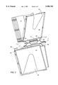
- FIG. 1 is an exploded perspective view of a sleeve used in a first embodiment of the inventive storage system
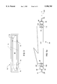
- FIG. 2 is a perspective view of a number of the sleeves of FIG. 1 mounted on vertebrae of a spine, with FIG. 2a a detailed view of section 1--1 in FIG. 2 and FIG. 2b a detailed view of section 2--2 in FIG. 2;
- FIG. 3 is an entry side view of a sleeve loaded with a cartridge type storage media
- FIG. 4a is a top side view of a sleeve using override bumps to retain storage media
- FIG. 4b is a close cut-away view of details of a left suitable override bump
- FIG. 4c is a close cut-away view of details of an alternate override bump design
- FIG. 5 is a perspective view of a clam-shell style case for storage of the spine and sleeves assembly of FIG. 2, with FIG. 5a a detailed view of section 1--1 in FIG. 5;
- FIG. 6 shows a wallet style housing for containing a number of the sleeves of FIG. 1 mounted on a spine
- FIG. 7 is a perspective view of a tray style storage unit for loose storage of a number of the sleeves of FIG. 1.
- the present invention includes a system of sleeves which may optionally be mounted on spines.
- the sleeves and spines in combination with a housing may form an overall storage system.
- the preferred embodiments of these are illustrated in the various figures, with the view of FIG. 1 particularly depicting the inventive sleeve and identifying it by the general reference character 10, the view of FIG. 2 particularly depicting the inventive spine and identifying it by the general reference character 12, and the views of FIGS. 5, 6, and 7 particularly depicting respective variations the storage system as a whole, and identifying these variations with the general reference characters 14a, 14b, and 14c.
- FIG. 1 illustrates in exploded perspective view one instance of the inventive sleeve 10. Included are an optional substrate 16 and two cover plates 18. Depending upon whether the substrate 16 is present, when the sleeve 10 is assembled (see e.g., FIG. 2) either one or two storage pockets 20 are formed which are each suitable for insertion of a unit of storage media (SM 22).
- SM 22 unit of storage media
- FIG. 4a An example DM 24 is shown in FIG. 4a in ghost view
- an example CM 26 is shown in FIG. 3 in a side view. No examples of ML 28 are shown in the figures.
- the substrate 16, the cover plates 18, and the storage pockets 20 formed therewith are all roughly rectangular in shape, and all accordingly can be defined as having an entry edge 30, which is that edge at which a unit of SM 22 is inserted; a back edge 32, opposite the entry edge 30; and a pair of side edges 34.
- the substrate 16 may be made of a non-scratching type material (e.g., a soft, low-friction, or highly polished material).
- the SM 22 can then be inserted into the storage pockets 20 with the information bearing side adjacent to the substrate 16, to protect the critical data thereon. This also orients the user information side of the SM 22 outward for easy user observation.
- the cover plates 18 will typically be made of transparent material (e.g., a clear plastic) to facilitate reading the surfaces of stored SM 22, the substrate 16 may be made of an opaque material so that users may readily discern whether a topmost storage pocket 20 is occupied, without confusion with an occupied lower storage pocket 20.
- transparent material e.g., a clear plastic
- FIG. 1 shows features used in a preferred technique which works well for sleeves 10 used to store lighter and less massive SM 22.
- the cover plates 18 employ a system of engaging tongues 36 and grooves 38 around the back edge 32 and the side edges 34.
- the particular arrangement of these tongues 36 and grooves 38 is not critical, so long as they permit the cover plates 18 to snap together during assembly.
- a series of corresponding locking notches 40 and locking holes 42 are provided in the tongues 36 and grooves 38.
- the cover plates 18 may be made the same, as are the those illustrated in FIG. 1, or they may be different.
- the substrate 16 can be retained in place between the cover plates 18 in a number of manners.
- the method shown in FIG. 1 employs a pair of retention ears 44, one located on each side edge 34 of the substrate 16 near the back edge 32. These two retention ears 44 engage with a pair of retention recesses 46, one each in the sandwiching cover plates 18, in a manner such that the substrate 16 is captured and cannot escape from between the cover plates 18, even as users later repeatedly slide SM 22 into and out of the storage pockets 20.
- each cover plate 18 An optional, but highly useful feature in each cover plate 18 is an access slot 48.
- This provides a means for users to easily withdraw a SM 22 from a storage pocket 20.
- the access slot 48 preferably extends into a cover plate 18 deep enough that a user can engage their fingertip in any center feature present in a SM 22 which is stored in a storage pocket 20 (see e.g., FIG. 4a), for adequate purchase to remove the SM 22.
- CM 26 such as CD's and CD ROM's are examples of some typical SM 22 having such center features.
- FIGS. 1 and 2 show a roughly right-triangle shape for right-handed users
- FIG. 4a shows an alternate which is roughly symmetrical and parabolic in shape.
- the use of relatively sizable access slots 48 also permit use of less material to manufacture the cover plates 18, and accordingly less press pressure if the manufacturing method is pressure molding.
- a key feature of the inventive sleeve 10 is optional mountability on the inventive spine 12.
- each cover plate 18 includes an extended region 50 alone its back edge 32, and at least one mounting tang 52 at the extreme of its back edge 32.
- a mounting slot 54 is formed along the back edge 32 of the sleeve 10.
- the mounting tangs 52 may extend the entire length of the back edge 32, but for less massive types of SM 22 the inventors prefer to use two mounting tangs 52 located at opposite ends of the back edge 32 of each cover plate 18. This arrangement provides four mounting tangs 52 on each sleeve 10, two in opposition at each end of the mounting slot 54, which provides adequate strength and mounting stability while also saving material.
- FIG. 2 illustrates a number of the sleeves 10 mounted on the inventive spine 12.
- the spine 12 includes a number of vertebrae 56, each containing a mounting track 58.
- the sleeves 10 are engaged to corresponding vertebrae 56 by sliding the mounting slot 54 over the mounting track 58, in the manner depicted by arrow 62.
- the vertebrae 56 are attached in a series to the spine 12.
- the method of vertebrae 56 to spine 12 attachment is a flexible hinge 60 (also sometimes referred to as a "piano hinge"), but other styles of hinge may of course also be used.
- a hinge such as the flexible hinge 60
- This roll-and-tumble action is analogous in many ways to how pages can be turned in a book, with the pulling of one page also turning sequential pages merely by forces transferred through the book spine.
- the sleeves 10 have no direct attachment to one another, since they attach to the vertebrae 56, which in turn are attached to the spine 12. In visual appearance, this type of operation somewhat resembles that of some common card files (e.g., those sold under the ROLODEX trademark), but the actual manner of operation here is quite different.
- FIG. 2a which is a view along section 1--1 in FIG. 2, depicts particular details of an empty mounting track 58.
- the mounting track 58 has both an entry end 64 and a stop end 66, each of which has a leading taper 68 to permit easy engagement with the mounting slot 54 of a sleeve 10.
- the entry end 64 includes an upward depending stop dimple 70, to assist in retaining a mounted sleeve 10 on a mounting track 58.
- the stop end 66 includes a stop tab 72, to prevent a mounted sleeve 10 from sliding too far along the mounting track 58.
- the stop end 66 can de dispensed with entirely, and two entry ends 64 provided instead.
- Retention of the sleeves 10 on the vertebrae 56 of the spine 12 can be also provided in a number of manners.
- the stop dimple 70 contributes to this goal.
- Another method is to have a slight interference fit between the entire mounting track 58 of the vertebrae 56 and the mounting tangs 52 of the sleeve 10.
- Yet another method is to have depressions to accept the mounting tangs 52 in a snap-in manner, say at the stop end 66 of the mounting track 58.
- FIG. 2b which is a view along section 2--2 of FIG. 2, the preferred embodiment of the mounting track 58 instead uses ramped regions 74 at both ends of the mounting track 58.
- ramped regions 74 are opposed, and make the mounting track 58 narrowest at its extremes.
- the ramped regions 74 partially form interference fits with the mounting tangs 52 of the sleeves 10 in the manner shown, thereby urging centering and further causing a mounted sleeve 10 to be held firmly in position upon a mounting track 58.
- the back edge 32 of the sleeve 10 has been that described as having the mounting slot 54.
- the side edges 34 could have the necessary features provided (e.g., the extended region 50 and mounting tangs 52), and the sleeve 10 could then be side mounted accordingly.
- the SM 22 it is generally desirable to be able to hold the SM 22 within the storage pockets 20, and this also may be accomplished in various manners. First, it may be done by suitably dimensioning the tongues 36 and grooves 38 so that the overall thickness of the sleeves 10 slightly compressably holds the SM 22 in place.
- the sleeves 10 depicted in FIG. 1 and FIG. 2 work well in this manner, with any present substrate 16 also playing a role in this scheme. This technique works for all shapes and sizes of SM 22, but it is particularly well suited for use on smaller and lighter SM 22, such as CD type DM 24 or CD associated ML 28.
- the cover plates 18 may be provided with compression rails 76, typically at least two, on either one or both cover plates 18.
- This rail based variation also operates by compressably retaining the SM 22 in place within the sleeve 10, but it makes considerably less surface contact with the SM 22.
- This rail based variation may even be used to avoid contact with sensitive parts of the SM 22.
- This rail based variation also works well for larger and more massive SM 22, particularly when relatively rigid material is used for the cover plates 18 and the overall sleeve 10 is stiff.
- the cover plates 18 may be provided with projections 78 which engage with particular features of the SM 22.
- the CM 26 is depicted having a cavity (shown in ghost form) on its lower side and tapers on its upper side which extend downwards towards its side edges.
- Both cover plates 18 are provided with the projections 78, to engage with the lower side cavity of an inserted instance of the particular CM 26, but the unused projection 78 is avoided due to the upper side tapering of the CM 26.
- An example of the particular shape of CM 26 envisioned here is the ZIPDISK (T/M IOMEGA Corporation).
- an override bump 80 may be provided in one or both side edges 34.
- the override bumps 80 can easily be added as part of the tongues 36 and grooves 38 system provided (FIG. 1). If the sleeves 10 are sized for smaller or lighter SM 22 and the material of construction is relatively flexible, e.g., plastic, the override bumps 80 can simply be made directly part of the side edge 34, as shown in FIG. 4a-b.
- the override bumps 80 can be placed on a flexible rib 82 which pivotally bends about an axis 84, as shown in FIG. 4c.
- the override bumps 80 may be made rounded and standing out about 0.020" to 0.040" for typical DM 24 like CD's, as shown in FIG. 4b. This works particularly well for retaining DM 24 in storage pockets, as shown in FIG.
- override bumps 80 are shown as spaced about 2" in from the entry edge 30 to well retain a standard sized CD (the DM 24 type SM 22 shown in ghost view) in the sleeve 10.
- the override bumps 80 do not necessarily have to be rounded or spaced inward along the side edges 34.
- the nature of the SM 22 or simply aesthetic or design preference may motivate the choice of shape, size, and placement of the override bump 80.
- the use of rib 82 mounted and pad-shaped override bumps 80 located very near the entry edge 30 may be desirable, or if the CM 26 needs to be very securely retained even multiple override bumps 80 along one or both side edges 34 may be used.
- slots 86 can be proved which correspond which respective override bumps 80.
- FIG. 5 depicts a container suitable for storage of the inventive sleeves 10, forming a storage system 14a variation.
- a clam-shell type case 88 is provided having a bottom case section 90 and a top case section 92.
- the case 88 accepts the spine 12 of FIG. 2, and permits easy and protected transport of a multiplicity of the sleeves 10 in a very compact yet highly protected manner. Typical desirable increments of sleeves 10 which can be stored in this manner are 5, 8, 10, 12, and even more.
- cases 88 such as that shown in FIG. 5, can be designed to accept appropriately sized spines 12.
- the spine 12 is made part of a hinge assembly 94 of the case 88.
- FIG. 5a depicting section 1--1 of FIG. 5, shows particular details of this hinge assembly 94.
- the bottom case section 90 has provided two outer hinge teeth 96, each having a dimple 98 which is inward depending.
- the top case section 92 has provided two middle hinge teeth 100, each having a through bore 102.
- the spine 12 has an inner hinge tooth 104, which has two opposed dimples 98 which are outward depending.
- the dimples 98 here act much in the manner of a conventional hinge pin. They engage the through bores 102 of the middle hinge teeth 100 to hold all of the teeth (outer hinge teeth 96, middle hinge teeth 100, and the inner hinge tooth 104) in rotatable alignment about axis 106. Since plastic is the preferred material for construction of the case 88, use of the dimples 98 (rather than a conventional hinge pin, for example) permits easy snap-together assembly and disassembly of the case 88.
- FIG. 6 depicts a storage system 14b variation.
- a soft sided wallet 108 is provided having two connected walls 110 and optionally a closing mechanism 112 to seal the wallet 108 closed.
- the walls 110 may be any of various materials, with flexible plastic sheet and fabric being two good examples.
- suitable closing mechanisms 112 include zippers (depicted in FIG. 6), tongue in groove systems (e.g., the T/M ZIPLOCK type closure system commonly used to seal plastic bags), and hook and loop systems (e.g., the T/M VELCRO system).
- FIG. 6 also depicts a variation of the spine 12, one which rather than using the centrally located inner hinge tooth 104 shown in FIG. 5a instead uses end flaps 114 on the spine 12 which attach to the wallet 108.
- the end flaps 114 insert loosely into pockets 116 in the walls 110 of the wallet 108.
- This provides the particular benefit that the previously noted roll-and-tumble action for the sleeves 10 may be accomplished here by merely pulling on or manipulating only the walls 110 of the wallet 108 (much like one can grasp a book only by its covers and fan the pages).
- a more solid connection of the spine 12 into the wallet 108 can, of course, also be used, but the inventors have found that this loose variation works well and is in keeping with the goal of flexibility.
- the end users of the storage system 14 may easily expand capacity, by moving spine 12 and sleeves 10 assemblies into different sized cases 88 or wallets 108 as desired.
- FIG. 7 depicts a storage system 14c variation.
- a tray 118 is provided which is suitable for loose storage and display of a multiplicity of sleeves 10.
- the tray 118 has a base 120, end walls 122 and side walls 124.
- the inside the tray 118 the base 120 may optionally have an upward arc shape (the case in FIG. 7) to facilitate easy roll-and-tumble type access to sleeves 10 stored in the tray 118.
- Optional indexing separators 126 may also be provided.
- the present sleeves 10 are well suited for application in storage of SM 22 which include DM 24, CM 26 and ML 28. If desired, the sleeves 10 may be constructed to alternately accept these types of contents interchangeably, thus serving a need for storage in which such contents can be associated as desired.
- the sleeves 10 are compact in size relative to conventional point-of sale storage containers used for SM 22, as well as being compact in size relative to many currently used storage systems. This permits users of the inventive sleeves 10 greater storage "density" than is available with such prior art. In particular, this should be of interest to users who have built up sizable libraries or who seek to compactly transport a multiplicity of SM 22.
Abstract
Description
Claims (26)
Priority Applications (1)
| Application Number | Priority Date | Filing Date | Title |
|---|---|---|---|
| US09/036,943 US5996785A (en) | 1996-01-04 | 1998-03-09 | Detachable module and flat object storage system |
Applications Claiming Priority (2)
| Application Number | Priority Date | Filing Date | Title |
|---|---|---|---|
| US959796P | 1996-01-04 | 1996-01-04 | |
| US09/036,943 US5996785A (en) | 1996-01-04 | 1998-03-09 | Detachable module and flat object storage system |
Related Parent Applications (1)
| Application Number | Title | Priority Date | Filing Date |
|---|---|---|---|
| PCT/US1997/000022 Continuation-In-Part WO1997025715A2 (en) | 1996-01-04 | 1997-01-03 | Detachable module disc and flat object storage system |
Publications (1)
| Publication Number | Publication Date |
|---|---|
| US5996785A true US5996785A (en) | 1999-12-07 |
Family
ID=21738628
Family Applications (2)
| Application Number | Title | Priority Date | Filing Date |
|---|---|---|---|
| US09/029,890 Expired - Fee Related US5915549A (en) | 1996-01-04 | 1997-01-03 | Detachable module disc and flat object storage system |
| US09/036,943 Expired - Fee Related US5996785A (en) | 1996-01-04 | 1998-03-09 | Detachable module and flat object storage system |
Family Applications Before (1)
| Application Number | Title | Priority Date | Filing Date |
|---|---|---|---|
| US09/029,890 Expired - Fee Related US5915549A (en) | 1996-01-04 | 1997-01-03 | Detachable module disc and flat object storage system |
Country Status (11)
| Country | Link |
|---|---|
| US (2) | US5915549A (en) |
| EP (1) | EP0886861B1 (en) |
| JP (1) | JP3215920B2 (en) |
| KR (1) | KR100311267B1 (en) |
| AT (1) | ATE249088T1 (en) |
| AU (1) | AU700140B2 (en) |
| BR (1) | BR9706957A (en) |
| CA (1) | CA2241415A1 (en) |
| DE (1) | DE69724597D1 (en) |
| IL (1) | IL125127A0 (en) |
| WO (1) | WO1997025715A2 (en) |
Cited By (22)
| Publication number | Priority date | Publication date | Assignee | Title |
|---|---|---|---|---|
| US20020094394A1 (en) * | 2001-01-12 | 2002-07-18 | Wynalda Robert Martin | Storage container for recorded media |
| US6450535B1 (en) * | 1999-05-07 | 2002-09-17 | R. R. Donnelley & Sons Company | Book for holding products such as compact discs and method of making the same |
| US20020170838A1 (en) * | 2001-02-20 | 2002-11-21 | Marsilio Ronald M. | Storage container for recorded media |
| US20030072604A1 (en) * | 2001-10-17 | 2003-04-17 | Lane Bradley P. | Disc management system |
| US20030150754A1 (en) * | 2002-02-07 | 2003-08-14 | Lepi China Limited, Hong Kong Sar | Storage system |
| US20030173247A1 (en) * | 2002-03-12 | 2003-09-18 | Melissa Boom Coburn | Ergonomic substrate container |
| US20030178330A1 (en) * | 2002-01-18 | 2003-09-25 | Bruce Dowdy | Method and apparatus for packaging compact discs for portable storage |
| US6626290B2 (en) | 2000-07-18 | 2003-09-30 | Nexpak Corporation | Storage container for recorded media |
| US20040026275A1 (en) * | 2000-09-15 | 2004-02-12 | Margetts Mark Geoffrey | Lamina storage device |
| US6715606B2 (en) | 2001-10-17 | 2004-04-06 | Robert P. Wray | Storage device for compact discs and the like |
| US20040245137A1 (en) * | 2003-02-12 | 2004-12-09 | Gelardi Tatiana L. | Book format data package |
| US20050103659A1 (en) * | 2003-02-12 | 2005-05-19 | Gelardi Tatiana L. | Means of attaching rigid pages to a book-like cover |
| US6896132B1 (en) * | 2001-03-29 | 2005-05-24 | Markus W. Frick | Storage media case |
| US20050206155A1 (en) * | 2004-03-17 | 2005-09-22 | Porreca Robert F | CD menu and song order control system |
| US6964335B1 (en) * | 2001-05-30 | 2005-11-15 | Digital Disc Corporation | Disc-media storage case and printed-media storage tray |
| US20050269221A1 (en) * | 2002-10-16 | 2005-12-08 | Vincent Demeaux | Storage device, in particular for disc media |
| US20070170078A1 (en) * | 2006-01-26 | 2007-07-26 | Encore Holdings Limited | Multiple disc storage container |
| US20080053849A1 (en) * | 2006-09-05 | 2008-03-06 | Ara Alan Sarkis Sabounjian | Binder |
| US20090032414A1 (en) * | 2007-07-31 | 2009-02-05 | Touch Automation | Method and apparatus for storing a disc |
| US20100020440A1 (en) * | 2008-07-25 | 2010-01-28 | Seagate Technology Llc | Low profile substrate shipper |
| US20100050327A1 (en) * | 2008-08-27 | 2010-03-04 | Kataoka Tetsurou | Chest protector |
| US20110031141A1 (en) * | 2009-08-04 | 2011-02-10 | Kwok Din Lau | Hingedly Connectable Disk Trays and Disk Protective Enclosure for Same |
Families Citing this family (9)
| Publication number | Priority date | Publication date | Assignee | Title |
|---|---|---|---|---|
| JPH11232817A (en) * | 1998-02-09 | 1999-08-27 | Sony Corp | Housing case for disk cartridge |
| CN1227666C (en) * | 1999-01-29 | 2005-11-16 | 高超明智公司 | A rack of compact discs |
| US6024214A (en) * | 1999-02-22 | 2000-02-15 | Cowan; David M. | Container for storing and displaying an article |
| US20030226813A1 (en) * | 2002-06-05 | 2003-12-11 | Taylor Charles E. | Storage and display rack for DVDs |
| US6955267B2 (en) * | 2002-06-05 | 2005-10-18 | Sharper Image Corporation | Storage and display rack for DVDs |
| US8158241B2 (en) * | 2003-03-04 | 2012-04-17 | Arkema France | Article displaying edgewise, angular multi-chromatic characteristics |
| US7159956B1 (en) * | 2004-02-02 | 2007-01-09 | Hatchell Sheila A | Disc case holding apparatus |
| US20070205119A1 (en) * | 2006-03-02 | 2007-09-06 | Glenn Stewart | Disk storage system |
| US8418849B2 (en) * | 2010-07-12 | 2013-04-16 | Multi Packaging Solutions, Inc. | Storage and packaging drawer device |
Citations (25)
| Publication number | Priority date | Publication date | Assignee | Title |
|---|---|---|---|---|
| US1287842A (en) * | 1915-11-06 | 1918-12-17 | Victor Talking Machine Co | Album for holding talking-machine records. |
| US4263357A (en) * | 1979-04-10 | 1981-04-21 | The Holson Company | Photo album page |
| US4327831A (en) * | 1979-07-07 | 1982-05-04 | Victor Company Of Japan, Limited | Disk record container |
| US4508366A (en) * | 1981-11-23 | 1985-04-02 | James Burn International Limited | Holders for computer disks and the like |
| US4602447A (en) * | 1984-05-01 | 1986-07-29 | Feingold Irene B | Window envelope for card file having guide rails |
| US4778047A (en) * | 1987-09-10 | 1988-10-18 | Lay Ding T | Laser disc storage container |
| US4781292A (en) * | 1986-04-04 | 1988-11-01 | Sacherman James E | Storage rack for compact discs, cassettes and the like |
| US4850731A (en) * | 1988-05-06 | 1989-07-25 | Youngs Ross O | Compact disc storage container with non-scratching surface |
| US4906057A (en) * | 1983-11-10 | 1990-03-06 | Rolodex Corporation | Closed portable card file |
| US5027950A (en) * | 1990-02-20 | 1991-07-02 | Julian Gutierrez | Display and holder assembly |
| US5096064A (en) * | 1990-06-04 | 1992-03-17 | Lakewood Industries, Inc. | Enclosure for information storage disks with a temporarily increasing width |
| US5154284A (en) * | 1991-11-07 | 1992-10-13 | Starkey Merrily J | Compact disc packaging |
| US5176250A (en) * | 1992-02-05 | 1993-01-05 | Billy Cheng | Handy disk storage box |
| US5295577A (en) * | 1993-03-26 | 1994-03-22 | Minter Theodore M | Storage system for compact discs |
| US5307926A (en) * | 1993-07-21 | 1994-05-03 | Greg Mee | Apparatus for storing media |
| US5385235A (en) * | 1992-07-06 | 1995-01-31 | Tdk Corporation | Casing for housing a cartridge |
| US5392906A (en) * | 1993-02-04 | 1995-02-28 | Taniyama; Yoshihiko | Expandable storage container system |
| US5392913A (en) * | 1993-07-19 | 1995-02-28 | Merrick; William | Storage holder device |
| US5415291A (en) * | 1992-09-04 | 1995-05-16 | Sony Corporation | Casing for multiple disc cartridges |
| US5513749A (en) * | 1995-05-11 | 1996-05-07 | Simmons; Charles B. | Storage case for multiple compact discs |
| US5520279A (en) * | 1994-12-30 | 1996-05-28 | Lin Shih Hsien | Compact disk carrying container |
| US5531324A (en) * | 1993-12-27 | 1996-07-02 | Showa Yuki Kabushiki Kaisha | Case for flat objects |
| US5540328A (en) * | 1993-06-11 | 1996-07-30 | Ricoh Co., Ltd. | Containing case for containing a disk-like recording medium |
| US5555977A (en) * | 1993-10-01 | 1996-09-17 | Roundhouse Products, Inc. | Sleeve and storage device for planar articles |
| US5558219A (en) * | 1995-01-23 | 1996-09-24 | Tenex Corporation | Diskette transporter with side cap surface steps |
Family Cites Families (5)
| Publication number | Priority date | Publication date | Assignee | Title |
|---|---|---|---|---|
| FR2436455A1 (en) * | 1978-09-15 | 1980-04-11 | Mollard Pierre | Multiple panel notice board - has radial swinging panels attached to vertical column by rings acting as hinges |
| GB2124475A (en) * | 1982-08-05 | 1984-02-22 | Byam Design And Manufacturing | Display assembly |
| US4844260A (en) * | 1988-08-02 | 1989-07-04 | Yow Yeh Plastic Co., Ltd. | Computer disc packing box |
| US5697498A (en) * | 1996-09-09 | 1997-12-16 | Fellowes Mfg. Co. | Carrying case for recorded media |
| US5749464A (en) * | 1996-11-01 | 1998-05-12 | Tenex Corporation | Compact disc binder and disc carrier used in same |
-
1997
- 1997-01-03 EP EP97903734A patent/EP0886861B1/en not_active Expired - Lifetime
- 1997-01-03 AU AU18227/97A patent/AU700140B2/en not_active Ceased
- 1997-01-03 BR BR9706957-4A patent/BR9706957A/en not_active IP Right Cessation
- 1997-01-03 CA CA002241415A patent/CA2241415A1/en not_active Abandoned
- 1997-01-03 KR KR1019980705175A patent/KR100311267B1/en not_active IP Right Cessation
- 1997-01-03 IL IL12512797A patent/IL125127A0/en unknown
- 1997-01-03 DE DE69724597T patent/DE69724597D1/en not_active Expired - Lifetime
- 1997-01-03 US US09/029,890 patent/US5915549A/en not_active Expired - Fee Related
- 1997-01-03 WO PCT/US1997/000022 patent/WO1997025715A2/en active IP Right Grant
- 1997-01-03 JP JP52527397A patent/JP3215920B2/en not_active Expired - Fee Related
- 1997-01-03 AT AT97903734T patent/ATE249088T1/en not_active IP Right Cessation
-
1998
- 1998-03-09 US US09/036,943 patent/US5996785A/en not_active Expired - Fee Related
Patent Citations (26)
| Publication number | Priority date | Publication date | Assignee | Title |
|---|---|---|---|---|
| US1287842A (en) * | 1915-11-06 | 1918-12-17 | Victor Talking Machine Co | Album for holding talking-machine records. |
| US4263357A (en) * | 1979-04-10 | 1981-04-21 | The Holson Company | Photo album page |
| US4327831A (en) * | 1979-07-07 | 1982-05-04 | Victor Company Of Japan, Limited | Disk record container |
| US4508366A (en) * | 1981-11-23 | 1985-04-02 | James Burn International Limited | Holders for computer disks and the like |
| US4906057A (en) * | 1983-11-10 | 1990-03-06 | Rolodex Corporation | Closed portable card file |
| US4602447A (en) * | 1984-05-01 | 1986-07-29 | Feingold Irene B | Window envelope for card file having guide rails |
| US4781292A (en) * | 1986-04-04 | 1988-11-01 | Sacherman James E | Storage rack for compact discs, cassettes and the like |
| US4778047A (en) * | 1987-09-10 | 1988-10-18 | Lay Ding T | Laser disc storage container |
| US4850731A (en) * | 1988-05-06 | 1989-07-25 | Youngs Ross O | Compact disc storage container with non-scratching surface |
| US5027950A (en) * | 1990-02-20 | 1991-07-02 | Julian Gutierrez | Display and holder assembly |
| US5096064A (en) * | 1990-06-04 | 1992-03-17 | Lakewood Industries, Inc. | Enclosure for information storage disks with a temporarily increasing width |
| US5154284A (en) * | 1991-11-07 | 1992-10-13 | Starkey Merrily J | Compact disc packaging |
| US5176250A (en) * | 1992-02-05 | 1993-01-05 | Billy Cheng | Handy disk storage box |
| US5385235A (en) * | 1992-07-06 | 1995-01-31 | Tdk Corporation | Casing for housing a cartridge |
| US5415291A (en) * | 1992-09-04 | 1995-05-16 | Sony Corporation | Casing for multiple disc cartridges |
| US5392906A (en) * | 1993-02-04 | 1995-02-28 | Taniyama; Yoshihiko | Expandable storage container system |
| US5295577A (en) * | 1993-03-26 | 1994-03-22 | Minter Theodore M | Storage system for compact discs |
| US5540328A (en) * | 1993-06-11 | 1996-07-30 | Ricoh Co., Ltd. | Containing case for containing a disk-like recording medium |
| US5392913A (en) * | 1993-07-19 | 1995-02-28 | Merrick; William | Storage holder device |
| US5307926A (en) * | 1993-07-21 | 1994-05-03 | Greg Mee | Apparatus for storing media |
| US5555977A (en) * | 1993-10-01 | 1996-09-17 | Roundhouse Products, Inc. | Sleeve and storage device for planar articles |
| US5715937A (en) * | 1993-10-01 | 1998-02-10 | Roundhouse Products, Inc. | Sleeve and storage device for compact discs and similar planar articles |
| US5531324A (en) * | 1993-12-27 | 1996-07-02 | Showa Yuki Kabushiki Kaisha | Case for flat objects |
| US5520279A (en) * | 1994-12-30 | 1996-05-28 | Lin Shih Hsien | Compact disk carrying container |
| US5558219A (en) * | 1995-01-23 | 1996-09-24 | Tenex Corporation | Diskette transporter with side cap surface steps |
| US5513749A (en) * | 1995-05-11 | 1996-05-07 | Simmons; Charles B. | Storage case for multiple compact discs |
Cited By (33)
| Publication number | Priority date | Publication date | Assignee | Title |
|---|---|---|---|---|
| US6450535B1 (en) * | 1999-05-07 | 2002-09-17 | R. R. Donnelley & Sons Company | Book for holding products such as compact discs and method of making the same |
| US6626290B2 (en) | 2000-07-18 | 2003-09-30 | Nexpak Corporation | Storage container for recorded media |
| US20040026275A1 (en) * | 2000-09-15 | 2004-02-12 | Margetts Mark Geoffrey | Lamina storage device |
| US7989041B2 (en) | 2001-01-12 | 2011-08-02 | Wynalda Jr Robert Martin | Storage container for recorded media |
| US20020094394A1 (en) * | 2001-01-12 | 2002-07-18 | Wynalda Robert Martin | Storage container for recorded media |
| US20020170838A1 (en) * | 2001-02-20 | 2002-11-21 | Marsilio Ronald M. | Storage container for recorded media |
| US6938758B2 (en) | 2001-02-20 | 2005-09-06 | Nexpak Corporation | Storage container for recorded media |
| US6896132B1 (en) * | 2001-03-29 | 2005-05-24 | Markus W. Frick | Storage media case |
| US6964335B1 (en) * | 2001-05-30 | 2005-11-15 | Digital Disc Corporation | Disc-media storage case and printed-media storage tray |
| US6942413B2 (en) * | 2001-10-17 | 2005-09-13 | Bradley P. Lane | Disc management system |
| US6715606B2 (en) | 2001-10-17 | 2004-04-06 | Robert P. Wray | Storage device for compact discs and the like |
| US20040057776A1 (en) * | 2001-10-17 | 2004-03-25 | Lane Bradley P. | Disc management system |
| US7008134B2 (en) * | 2001-10-17 | 2006-03-07 | Lane Bradley P | Disc management system |
| US20030072604A1 (en) * | 2001-10-17 | 2003-04-17 | Lane Bradley P. | Disc management system |
| US20030178330A1 (en) * | 2002-01-18 | 2003-09-25 | Bruce Dowdy | Method and apparatus for packaging compact discs for portable storage |
| US20030150754A1 (en) * | 2002-02-07 | 2003-08-14 | Lepi China Limited, Hong Kong Sar | Storage system |
| US7789241B2 (en) * | 2002-03-12 | 2010-09-07 | Seagate Technology Llc | Ergonomic substrate container |
| US20030173247A1 (en) * | 2002-03-12 | 2003-09-18 | Melissa Boom Coburn | Ergonomic substrate container |
| US20050269221A1 (en) * | 2002-10-16 | 2005-12-08 | Vincent Demeaux | Storage device, in particular for disc media |
| US20040245137A1 (en) * | 2003-02-12 | 2004-12-09 | Gelardi Tatiana L. | Book format data package |
| US20050103659A1 (en) * | 2003-02-12 | 2005-05-19 | Gelardi Tatiana L. | Means of attaching rigid pages to a book-like cover |
| US20050206155A1 (en) * | 2004-03-17 | 2005-09-22 | Porreca Robert F | CD menu and song order control system |
| US7726475B2 (en) * | 2006-01-26 | 2010-06-01 | Encore Holdings Limited | Multiple disc storage container |
| US20100200441A1 (en) * | 2006-01-26 | 2010-08-12 | Encore Holdings Limited | Multiple disc storage container |
| US20070170078A1 (en) * | 2006-01-26 | 2007-07-26 | Encore Holdings Limited | Multiple disc storage container |
| US20080053849A1 (en) * | 2006-09-05 | 2008-03-06 | Ara Alan Sarkis Sabounjian | Binder |
| US20090032414A1 (en) * | 2007-07-31 | 2009-02-05 | Touch Automation | Method and apparatus for storing a disc |
| US8783455B2 (en) * | 2007-07-31 | 2014-07-22 | Ncr Corporation | Method and apparatus for storing a disc |
| US20100020440A1 (en) * | 2008-07-25 | 2010-01-28 | Seagate Technology Llc | Low profile substrate shipper |
| US20100050327A1 (en) * | 2008-08-27 | 2010-03-04 | Kataoka Tetsurou | Chest protector |
| US8205273B2 (en) * | 2008-08-27 | 2012-06-26 | Honda Motor Co., Ltd. | Chest protector |
| US20110031141A1 (en) * | 2009-08-04 | 2011-02-10 | Kwok Din Lau | Hingedly Connectable Disk Trays and Disk Protective Enclosure for Same |
| US8763801B2 (en) * | 2009-08-04 | 2014-07-01 | Finest Products Limited | Hingedly connectable disk trays and disk protective enclosure for same |
Also Published As
| Publication number | Publication date |
|---|---|
| KR100311267B1 (en) | 2002-09-05 |
| AU1822797A (en) | 1997-08-01 |
| AU700140B2 (en) | 1998-12-24 |
| CA2241415A1 (en) | 1997-07-17 |
| KR19990077042A (en) | 1999-10-25 |
| EP0886861B1 (en) | 2003-09-03 |
| EP0886861A2 (en) | 1998-12-30 |
| BR9706957A (en) | 1999-12-21 |
| ATE249088T1 (en) | 2003-09-15 |
| JPH11504601A (en) | 1999-04-27 |
| WO1997025715A3 (en) | 1997-09-18 |
| DE69724597D1 (en) | 2003-10-09 |
| JP3215920B2 (en) | 2001-10-09 |
| WO1997025715A2 (en) | 1997-07-17 |
| IL125127A0 (en) | 1999-01-26 |
| EP0886861A4 (en) | 2000-07-26 |
| US5915549A (en) | 1999-06-29 |
Similar Documents
| Publication | Publication Date | Title |
|---|---|---|
| US5996785A (en) | Detachable module and flat object storage system | |
| US4823950A (en) | Storage arrangement for optical discs and their containers | |
| EP0658148B1 (en) | A wallet style compact disc storage unit | |
| US5697498A (en) | Carrying case for recorded media | |
| US5188228A (en) | Compact disk holder | |
| US5794796A (en) | Storage rack for retaining software devices having multiple configurations | |
| US6179121B1 (en) | Device for transport and splayed display of media | |
| JPH0889379A (en) | Disk cartridge holding apparatus and its connection method | |
| US20100200441A1 (en) | Multiple disc storage container | |
| US8011503B2 (en) | Modular optical disc media storage system | |
| US7066325B2 (en) | Storage container for recorded media | |
| US6712203B2 (en) | Compact disc case | |
| EP1372154A2 (en) | Compact disc tray | |
| US5088674A (en) | Bracket for wall mounting a compact disk case | |
| JP7329821B2 (en) | Recorded media display case | |
| US20090321438A1 (en) | Housings | |
| AU707542B2 (en) | A wallet style compact disc storage unit | |
| CA2316096A1 (en) | Loose-leaf compact disc pocket hanger | |
| US20030070945A1 (en) | Storage device for compact discs and the like | |
| US7458459B2 (en) | Container and method of making a container | |
| US20030150754A1 (en) | Storage system | |
| JP3032343U (en) | Mini disk case with storage pocket for recording material | |
| JPH10211983A (en) | Storage body for storing a plurality of cases | |
| WO2007103122A2 (en) | Game case for card type games | |
| JP2006036261A (en) | Disk storing body |
Legal Events
| Date | Code | Title | Description |
|---|---|---|---|
| AS | Assignment |
Owner name: CREATIVE POINT, INC., CALIFORNIA Free format text: ASSIGNMENT OF ASSIGNORS INTEREST;ASSIGNORS:PALMER, PETER J.;PALMER, CHRISTOPHER G.;GELPHMAN, STEVEN A.;REEL/FRAME:008513/0960 Effective date: 19970103 |
|
| AS | Assignment |
Owner name: CREATIVE POINT, INC., CALIFORNIA Free format text: ASSIGNMENT OF ASSIGNORS INTEREST;ASSIGNORS:PALMER, CHRISTOPHER G.;PALMER, PETER J.;GELPHMAN, STEVEN A.;REEL/FRAME:009024/0541 Effective date: 19980309 |
|
| AS | Assignment |
Owner name: MEAD CORPORATION, THE, OHIO Free format text: ASSIGNMENT OF ASSIGNORS INTEREST;ASSIGNOR:CREATIVE POINT, INC.;REEL/FRAME:009748/0376 Effective date: 19981019 |
|
| FEPP | Fee payment procedure |
Free format text: PAYOR NUMBER ASSIGNED (ORIGINAL EVENT CODE: ASPN); ENTITY STATUS OF PATENT OWNER: LARGE ENTITY |
|
| AS | Assignment |
Owner name: LASERLINE COMPANY,THE, CONNECTICUT Free format text: ASSIGNMENT OF ASSIGNORS INTEREST;ASSIGNOR:MEAD CORPORATION,THE;REEL/FRAME:013484/0856 Effective date: 20020524 |
|
| FPAY | Fee payment |
Year of fee payment: 4 |
|
| REMI | Maintenance fee reminder mailed | ||
| REMI | Maintenance fee reminder mailed | ||
| LAPS | Lapse for failure to pay maintenance fees | ||
| STCH | Information on status: patent discontinuation |
Free format text: PATENT EXPIRED DUE TO NONPAYMENT OF MAINTENANCE FEES UNDER 37 CFR 1.362 |
|
| FP | Lapsed due to failure to pay maintenance fee |
Effective date: 20071207 |