US5996942A - Autonomous solar torque management - Google Patents
Autonomous solar torque management Download PDFInfo
- Publication number
- US5996942A US5996942A US08/934,982 US93498297A US5996942A US 5996942 A US5996942 A US 5996942A US 93498297 A US93498297 A US 93498297A US 5996942 A US5996942 A US 5996942A
- Authority
- US
- United States
- Prior art keywords
- momentum
- inertial
- sub
- yaw
- spacecraft
- Prior art date
- Legal status (The legal status is an assumption and is not a legal conclusion. Google has not performed a legal analysis and makes no representation as to the accuracy of the status listed.)
- Expired - Lifetime
Links
- 238000000034 method Methods 0.000 claims abstract description 37
- 230000008859 change Effects 0.000 claims abstract description 20
- 238000004891 communication Methods 0.000 claims description 6
- 230000008569 process Effects 0.000 claims description 3
- 238000005070 sampling Methods 0.000 claims 2
- 238000003384 imaging method Methods 0.000 description 6
- 230000008901 benefit Effects 0.000 description 5
- 238000010586 diagram Methods 0.000 description 5
- 230000007774 longterm Effects 0.000 description 5
- 238000004088 simulation Methods 0.000 description 4
- 238000009825 accumulation Methods 0.000 description 3
- 238000003491 array Methods 0.000 description 3
- 238000006243 chemical reaction Methods 0.000 description 3
- 238000013459 approach Methods 0.000 description 2
- 230000000694 effects Effects 0.000 description 2
- 230000007613 environmental effect Effects 0.000 description 2
- 238000005259 measurement Methods 0.000 description 2
- 230000003287 optical effect Effects 0.000 description 2
- 230000000737 periodic effect Effects 0.000 description 2
- 230000004044 response Effects 0.000 description 2
- 230000006641 stabilisation Effects 0.000 description 2
- 238000011105 stabilization Methods 0.000 description 2
- 230000001052 transient effect Effects 0.000 description 2
- 230000007704 transition Effects 0.000 description 2
- BCCGKQFZUUQSEX-WBPXWQEISA-N (2r,3r)-2,3-dihydroxybutanedioic acid;3,4-dimethyl-2-phenylmorpholine Chemical compound OC(=O)[C@H](O)[C@@H](O)C(O)=O.OC(=O)[C@H](O)[C@@H](O)C(O)=O.O1CCN(C)C(C)C1C1=CC=CC=C1 BCCGKQFZUUQSEX-WBPXWQEISA-N 0.000 description 1
- 238000005452 bending Methods 0.000 description 1
- 238000005094 computer simulation Methods 0.000 description 1
- 238000012937 correction Methods 0.000 description 1
- 238000013461 design Methods 0.000 description 1
- 230000005284 excitation Effects 0.000 description 1
- 238000010304 firing Methods 0.000 description 1
- 230000007246 mechanism Effects 0.000 description 1
- 230000001932 seasonal effect Effects 0.000 description 1
- 230000003442 weekly effect Effects 0.000 description 1
Images


Classifications
-
- B—PERFORMING OPERATIONS; TRANSPORTING
- B64—AIRCRAFT; AVIATION; COSMONAUTICS
- B64G—COSMONAUTICS; VEHICLES OR EQUIPMENT THEREFOR
- B64G1/00—Cosmonautic vehicles
- B64G1/22—Parts of, or equipment specially adapted for fitting in or to, cosmonautic vehicles
- B64G1/24—Guiding or controlling apparatus, e.g. for attitude control
- B64G1/28—Guiding or controlling apparatus, e.g. for attitude control using inertia or gyro effect
- B64G1/285—Guiding or controlling apparatus, e.g. for attitude control using inertia or gyro effect using momentum wheels
-
- B—PERFORMING OPERATIONS; TRANSPORTING
- B64—AIRCRAFT; AVIATION; COSMONAUTICS
- B64G—COSMONAUTICS; VEHICLES OR EQUIPMENT THEREFOR
- B64G1/00—Cosmonautic vehicles
- B64G1/22—Parts of, or equipment specially adapted for fitting in or to, cosmonautic vehicles
- B64G1/24—Guiding or controlling apparatus, e.g. for attitude control
- B64G1/244—Spacecraft control systems
-
- B—PERFORMING OPERATIONS; TRANSPORTING
- B64—AIRCRAFT; AVIATION; COSMONAUTICS
- B64G—COSMONAUTICS; VEHICLES OR EQUIPMENT THEREFOR
- B64G1/00—Cosmonautic vehicles
- B64G1/22—Parts of, or equipment specially adapted for fitting in or to, cosmonautic vehicles
- B64G1/24—Guiding or controlling apparatus, e.g. for attitude control
- B64G1/36—Guiding or controlling apparatus, e.g. for attitude control using sensors, e.g. sun-sensors, horizon sensors
- B64G1/365—Guiding or controlling apparatus, e.g. for attitude control using sensors, e.g. sun-sensors, horizon sensors using horizon or Earth sensors
-
- B—PERFORMING OPERATIONS; TRANSPORTING
- B64—AIRCRAFT; AVIATION; COSMONAUTICS
- B64G—COSMONAUTICS; VEHICLES OR EQUIPMENT THEREFOR
- B64G1/00—Cosmonautic vehicles
- B64G1/22—Parts of, or equipment specially adapted for fitting in or to, cosmonautic vehicles
- B64G1/24—Guiding or controlling apparatus, e.g. for attitude control
- B64G1/36—Guiding or controlling apparatus, e.g. for attitude control using sensors, e.g. sun-sensors, horizon sensors
- B64G1/366—Guiding or controlling apparatus, e.g. for attitude control using sensors, e.g. sun-sensors, horizon sensors using magnetometers
Definitions
- This invention relates generally to spacecraft and, in particular, to methods and apparatus for maintaining a 3-axis stabilized spacecraft in a desired orbital configuration.
- Spacecraft perform various maneuvers after they are launched into space and once they are on-station in an intended orbit. After the spacecraft is on-station in a selected orbit, various forces (e.g., solar and/or other environmental disturbance torques, such as magnetic torques) may act on the spacecraft and cause the spacecraft to drift away from its selected orbit into another, incorrect orbit. Thus, periodic (e.g., daily, weekly, or monthly) orbital maneuvers are often required to return the spacecraft to the correct orbit. These types of maneuvers are known as station-keeping maneuvers.
- forces e.g., solar and/or other environmental disturbance torques, such as magnetic torques
- periodic orbital maneuvers are often required to return the spacecraft to the correct orbit. These types of maneuvers are known as station-keeping maneuvers.
- the precise control of the spacecraft's attitude is essential to orient the spacecraft's payload, such as communication or imaging hardware, to a preselected planetary location and/or to correctly orient the spacecraft's thrust vector.
- spacecraft are typically equipped with closed-loop control systems which enable the attitude of the spacecraft to be controlled within pre-established deadband limits.
- Such control systems often employ spacecraft thrusters for selectively producing torques on the spacecraft for correcting the spacecraft attitude.
- a typical geosynchronous satellite is designed to minimize solar torque imbalance. This is typically accomplished with symmetric solar array design, with solar arrays being located on the north and south side of the spacecraft, or in a configuration with the solar array located on the south side, balanced by a solar sail on the north side. These appendages extend from a spacecraft bus. Residual solar and environmental disturbance torques are stored in momentum wheels that are then unloaded periodically using, by example, the spacecraft's thrusters, magnetic torquers, trim tabs, or solar panel angle adjustments.
- This invention provides a method and apparatus to zero a long term roll and yaw momentum accumulation on a spacecraft having a single solar array and trim tab.
- the use of the teaching of this invention provides enhanced stability in the presence of large solar torques.
- This invention uses a solar array as a torque adjustment actuator while requiring only a very small solar array misalignment.
- Advantages of this invention include: autonomous operation; a balancing of average solar torque through actuator adjustment; a balancing of both roll and yaw torques via a single solar array and trim tab; and tachometer-only direct sensor measurement.
- a method in accordance with this invention for maintaining a spacecraft in a desired orbital configuration, comprises the steps of: (a) recording a history of yaw momentum stored in momentum wheels; (b) estimating an average inertial torque and momentum over a previous time interval (such as one day); (c) determining a desired change in inertial torques using Proportional Integral Derivative (PID) control law; (d) commanding a change in satellite trim tab and solar array position from a desired change in solar torque; and (e) slewing the trim tab and solar array a predetermined amount.
- PID Proportional Integral Derivative
- FIG. 1 is diagram of a spacecraft in accordance with this invention
- FIG. 2 is a block diagram of a solar sailing control system in accordance with this invention.
- FIG. 3 is a block diagram of a PID control law system controller in accordance with this invention.
- FIGS. 4A and 4B are graphs illustrating the stability characteristics of the PID controller of FIG. 3;
- FIGS. 5A-5C are graphs illustrating the closed loop frequency response characteristics of the PID controller of FIG. 3;
- FIGS. 6A-6H are graphs illustrating a result of a long term simulation of the operation of the invention, the simulation assuming a V-mode operation with solar sailing and a station keeping transient;
- FIG. 7 is a logic flow diagram that illustrates a method in accordance with this invention.
- FIG. 8 is an elevational view showing the solar array panel and trim tab in greater detail
- FIG. 9A is an elevational view of a spacecraft that is suitable for practicing this invention.
- FIG. 9B is an elevational view of an imager scan assembly that forms a portion of the payload of the spacecraft of FIG. 9A;
- FIG. 9C is an elevational, exploded view of the imager payload that includes the imager scan assembly of FIG. 9B, and which further shows spacecraft and imager axes;
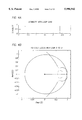
- FIG. 9D illustrates the imager coordinate frame of the imager shown in FIG. 9C.
- This invention provides a method and apparatus to zero a long term roll and yaw momentum accumulation on a spacecraft 10 having a single solar array 12, trim tab 14, and a sail/boom appendage 16, all of which extend from a spacecraft bus 18, as shown in FIG. 1.
- the spacecraft bus 18 is assumed to contain a programmable controller 18A, such as a microprocessor, and a three axis, momentum wheel based stabilization system 18B.
- FIGS. 9A-9D for showing an exemplary embodiment of the spacecraft 10 in greater detail.
- the spacecraft 10 includes a bus 10A from which protrudes a telemetry and control (T&C) antenna 10B, a magnetometer 10C, an Earth sensor 10C', and an entrance aperture 10D of an imager payload. Also attached to the bus 10A are the solar panels 12, which support the trim tab 14, and the solar sail 16.
- FIG. 9B shows a portion of the imaging payload, in particular a scan mirror 10H and its associated components.
- FIG. 9C illustrates the orientation of the scan mirror assembly and scan mirror 10H to the optical aperture 10D, as well as to a telescope 10I and detector 10J. The various spacecraft and imager axes are also shown.
- FIG. 9D illustrates the coordinate frame of the imager 10J, and shows an exemplary image of the earth overlaid on the imager.
- FIG. 8 shows in greater detail a portion of the solar array panel 12 and the trim tab panel 14.
- a pair of stepper motors 15a and 15b work in conjunction with a rotational mechanism 15c for adjusting, in discrete steps, an angular orientation of the trim tab panel 14 with respect to the solar array panel 14.
- the angular orientation of the solar array panel 12 with respect to the body of the spacecraft 10 can also be similarly adjusted.
- Suitable dimensions for the solar arrays are 100 ⁇ 100 inches, for a total solar panel (two arrays) dimension of 200 ⁇ 100 inches.
- Exemplary dimensions for the trim tab 14 are 70 inches (width) by 50 inches (length).
- This invention provides enhanced stability in the presence of large solar torques, and uses the solar array 12 as a torque adjustment actuator while requiring only a very small solar array misalignment from a normal sun-pointing configuration.
- Advantages of this invention include: autonomous operation; a balancing of average solar torque through actuator adjustment; a balancing of both roll and yaw torques via the single solar array 12 and trim tab 14; and tachometer-only direct sensor measurement.
- This invention employs a novel method for on-board autonomous control of inertial roll and yaw solar torque management.
- This approach is applicable to any three axis, wheel controlled spacecraft that includes the on-board processor 18A, a solar array 12, and a trim tab 14.
- FIGS. 1 and 8 illustrate one such spacecraft configuration, the illustrated configuration should not be viewed as a limitation on the practice of this invention.
- the presently preferred controller topology and algorithm permit control of the inertial roll and yaw solar torque at its source.
- the on-board controller 18A uses only measured wheel speed as an input and produces commanded trim tab 14 and solar array 12 angular adjustments at periodic intervals, such as twice per day.
- the angular adjustments of these optical surfaces serves to control the inertial roll and yaw solar torque directly.
- roll/yaw momentum are maintained to within a desired operating range, obviating or reducing the need to perform momentum unloads with spacecraft thrusters. This advantage is particularly important when using payloads that require a high level of short term attitude stability, such as imaging and certain communications payloads.
- FIG. 2 depicts the controller 18A having an input coupled to an output of a spacecraft dynamics (S/C dynamics) 20 and the momentum wheel control loop 18B.
- the controller 18A includes a Least Squares (LS) Estimate of Torque and Momentum block 22 which provides outputs to a trim tab control channel and to a solar array control channel.
- the LS block 22 estimates inertial momentum and torque from yaw momentum.
- the trim tab control channel includes a first Proportional Integral Derivative (PID) control law block 24 coupled to a delta torque to delta trim tab angle control block 26.
- the solar array control channel includes a second PID control law block 28 coupled to a delta torque to delta solar array angle control block 30.
- PID Proportional Integral Derivative
- Desired changes in inertial torques are computed using the PID control law blocks 24 and 28.
- Control blocks 26 and 28 provide delta trim tab angle commands and delta solar array angle commands, respectively, to the trim tab 14 and solar array 12, which are assumed to form a part of the S/C dynamics block 20.
- the adjustable trim tab 14 is used for making inertial roll adjustments, while the adjustable solar array is used for making inertial yaw adjustments.
- the delta trim tab angle commands and delta solar array angle commands are updated twice per 24 hours, although other update intervals could be used.
- the LS model of yaw momentum that is periodically solved by the LS estimator block 22 is given by the following expression.
- the LS controller 22 periodically samples the yaw momentum.
- the yaw momentum is sampled 24 times per 24 hours.
- the controller 22 periodically solves for the LS model, for example twice per 24 hours, each time using the sampled yaw momentum for the previous 12 hours.
- the controller 22 discards the radiance gradiance and antenna torque parameters (X 1 , X 6 , and X 7 ), as it has been found that it is not necessary to adjust for their effects.
- the estimated momentum and torques are employed by the PID control law blocks 24 and 28 to derive changes in (i.e., delta) roll and yaw torques, and at Block E the delta roll and yaw torques are acted on by delta torque controllers 26 and 30 to adjust the angle of the trim tab 14 and the angle of the solar array 12.
- the controller 22 holds the torque parameters if a spacecraft thruster has been fired during some predetermined prior interval, such as 12 hours. Firing the thruster has been found to corrupt the torque estimate. As such, only the momentum estimate is used in Block E, in conjunction with the previous torque estimate.
- the conversion from the commanded torque to a change in angle for the solar array 12, performed by the delta torque to delta solar array angle controller 30, is a linear process, wherein small misalignments in the angle of the solar array 12 produce "pure" inertial yaw torque.
- the conversion from the commanded torque to a change in angle for the trim tab 14, performed by the delta torque to delta tab angle controller, is instead proportional to the cosine of the sun vector and the trim tab normal. As such, a knowledge of sun declination is required on the spacecraft.
- FIG. 3 is a block diagram representative of the PID control law blocks 24 and 28.
- Input summing node 38 provides an output to a delay block 40 which represents the summation of input samples.
- the alpha block 42 represents a "leaky" integrator function, thereby effectively reducing the effect or weight of older yaw or roll momentum estimate values.
- the output of delay block 40 is applied to an integral gain block (Ki) 44, which provides an output to summing node 50.
- Ki integral gain block
- Also applied to the summing node 50 is an output of a position gain block 46, which receives the momentum estimate output from LS estimate block 22, and an output of a derivative gain block 48, which receives the torque estimate output from LS estimate block 22.
- the output of the summation block 50 is a delta torque command signal, which is applied to the appropriate delta torque to delta tab angle control block 26 or the delta torque to delta solar array angle control block 30.
- the summer solstice (SS) solar torque was established assuming a nominal earth's magnetic B-field.
- the autumn equinox (AQ) solar torque was established assuming a moderate magnetic storm, as was the winter solstice (WS) solar torque, with station keeping.
- the AQ solar torque further assumed a (daily) pitch unload and a yaw (momentum) unload.
- FIGS. 4A and 4B are graphs illustrating modeled stability characteristics of the PID controller of FIG. 3;
- FIGS. 5A-5C are graphs illustrating modeled closed loop frequency response characteristics of the PID controller of FIG. 3;
- FIGS. 6A-6H are graphs illustrating a result of a long term (15 day) simulation of the operation of the invention. These graphs assume V mode operation, and a single station keeping (SK) transient is shown occurring about day 7.
- SK station keeping
- V mode refers to operation with both momentum wheels (M1 and M2), which is normal operation, as opposed to an L mode that would refer to operation with one momentum wheel and a reaction wheel (RW), referred to as the L1 mode when operating with M1 and the RW, or as the L2 mode when operating with M2 and the RW.
- M1 and M2 momentum wheels
- RW reaction wheel
- this invention has been found maximize yaw attitude stability for imaging and other spacecraft missions, to provide automatic long-term roll/yaw momentum management without requiring thruster unloads, and to prevent excessive hz (yaw) momentum accumulation in the momentum wheels 18B, all by using minimal angular trim tab and solar array adjustments (e.g., twice per day, spaced 12 hours apart).
- the angular adjustments of the solar array 12 and trim tab 14 can be performed while imaging.
- the solar array angular adjustments can be performed by adding or dropping double steps (0.014°/double step) from the nominal sun tracking angle at orbital rate.
- the use of this invention has been found to have no impact on line of sight (LOS) stability of the imager payload.
- the frequency of adding or dropping double steps is low, thus minimizing any disturbance to the pitch loop.
- the frequency of trim tab stepping (e.g., 0.01875°/step) is also low, thereby minimizing any disturbance to the short term momentum wheel control (LQG) loop.
- LQG short term momentum wheel control
- Successive steps are deadbeat to minimize any excitation of the first out-of-plane bending mode.
- the worst-case adjustment angles can be less than 1° for the trim tab 14 and 0.2° for the solar array 12 (see FIGS. 6D and 6H).
Abstract
Description
hz(t)=X.sub.1 +X.sub.2 cos (w.sub.0 t)+X.sub.3 sin (w.sub.0 t)+X.sub.4 t cos (w.sub.0 t)+X.sub.5 t sin (w.sub.0 t)+X.sub.6 cos)2w.sub.0 t)+X.sub.7 sin (2w.sub.0 t)
Claims (20)
hz(t)=X.sub.1 +X.sub.2 cos (w.sub.0 t)+X.sub.3 sin (w.sub.0 t)+X.sub.4 t cos (w.sub.0 t)+X.sub.5 t sin (w.sub.0 t)+X.sub.6 cos)2w.sub.0 t)+X.sub.7 sin (2w.sub.0 t)
hz(t)=X.sub.1 +X.sub.2 cos (w.sub.0 t)+X.sub.3 sin (w.sub.0 t)+X.sub.4 t cos (w.sub.0 t)+X.sub.5 t sin (w.sub.0 t)+X.sub.6 cos)2w.sub.0 t)+X.sub.7 sin (2w.sub.0 t)
Priority Applications (6)
| Application Number | Priority Date | Filing Date | Title |
|---|---|---|---|
| US08/934,982 US5996942A (en) | 1996-10-16 | 1997-09-22 | Autonomous solar torque management |
| AU48251/97A AU4825197A (en) | 1996-10-16 | 1997-10-14 | Autonomous solar torque management |
| JP10518638A JP2001502272A (en) | 1996-10-16 | 1997-10-14 | Autonomous solar radiation torque management |
| PCT/US1997/018893 WO1998016424A1 (en) | 1996-10-16 | 1997-10-14 | Autonomous solar torque management |
| EP97911013A EP0932549B1 (en) | 1996-10-16 | 1997-10-14 | Autonomous solar torque management |
| DE69720750T DE69720750D1 (en) | 1996-10-16 | 1997-10-14 | AUTONOMOUS MANAGEMENT OF A SUNWIND-INDUCTED TORQUE |
Applications Claiming Priority (2)
| Application Number | Priority Date | Filing Date | Title |
|---|---|---|---|
| US2859496P | 1996-10-16 | 1996-10-16 | |
| US08/934,982 US5996942A (en) | 1996-10-16 | 1997-09-22 | Autonomous solar torque management |
Publications (1)
| Publication Number | Publication Date |
|---|---|
| US5996942A true US5996942A (en) | 1999-12-07 |
Family
ID=26703879
Family Applications (1)
| Application Number | Title | Priority Date | Filing Date |
|---|---|---|---|
| US08/934,982 Expired - Lifetime US5996942A (en) | 1996-10-16 | 1997-09-22 | Autonomous solar torque management |
Country Status (6)
| Country | Link |
|---|---|
| US (1) | US5996942A (en) |
| EP (1) | EP0932549B1 (en) |
| JP (1) | JP2001502272A (en) |
| AU (1) | AU4825197A (en) |
| DE (1) | DE69720750D1 (en) |
| WO (1) | WO1998016424A1 (en) |
Cited By (7)
| Publication number | Priority date | Publication date | Assignee | Title |
|---|---|---|---|---|
| US6318675B1 (en) * | 1999-10-11 | 2001-11-20 | Hughes Electronics Corporation | Solar wing thermal shock compensation using solar wing position actuator |
| US6381520B1 (en) * | 2000-07-10 | 2002-04-30 | Space Systems/Loral, Inc. | Sun seeking solar array control system and method |
| US20040095833A1 (en) * | 1999-09-27 | 2004-05-20 | Intel Corporation | Error correction apparatus, systems, and methods |
| US20050077425A1 (en) * | 2003-10-10 | 2005-04-14 | Raymond Payette | Thruster for propelling and directing a vehicle without interacting with environment and method for making the same |
| US20110309191A1 (en) * | 2010-06-17 | 2011-12-22 | Lockheed Martin Corporation | System and Method For Desaturation of a Control Moment Gyroscope |
| US20120303185A1 (en) * | 2011-05-25 | 2012-11-29 | Space Systems/Loral, Inc. | Spacecraft momentum management using solar array |
| US10618678B1 (en) * | 2015-10-20 | 2020-04-14 | Space Systems/Loral, Llc | Self-balancing solar array |
Families Citing this family (2)
| Publication number | Priority date | Publication date | Assignee | Title |
|---|---|---|---|---|
| JP2007216750A (en) * | 2006-02-15 | 2007-08-30 | Mitsubishi Electric Corp | Artificial satellite and disturbance canceling method |
| JP6426524B2 (en) * | 2015-04-15 | 2018-11-21 | 三菱電機株式会社 | Satellite, storage angular momentum removal device and ground station device |
Citations (30)
| Publication number | Priority date | Publication date | Assignee | Title |
|---|---|---|---|---|
| US3304028A (en) * | 1964-08-11 | 1967-02-14 | Hugh L Dryden | Attitude control for spacecraft |
| US4010921A (en) * | 1975-08-20 | 1977-03-08 | The United States Of America As Represented By The Secretary Of The Air Force | Spacecraft closed loop three-axis momentum unloading system |
| US4084772A (en) * | 1976-01-28 | 1978-04-18 | Rca Corporation | Roll/yaw body steering for momentum biased spacecraft |
| US4272045A (en) * | 1979-03-29 | 1981-06-09 | Rca Corporation | Nutation damping in a dual-spin spacecraft |
| US4489383A (en) * | 1981-10-16 | 1984-12-18 | Rca Corporation | Closed-loop magnetic roll/yaw control system for high inclination orbit satellites |
| US4506312A (en) * | 1982-03-09 | 1985-03-19 | Ford Aerospace & Communications Corporation | Apparatus for controlling the speed of a rotating body |
| US4521855A (en) * | 1981-07-27 | 1985-06-04 | Ford Aerospace & Communications Corporation | Electronic on-orbit roll/yaw satellite control |
| US4599697A (en) * | 1982-08-11 | 1986-07-08 | Ford Aerospace & Communications Corporation | Digital PWPF three axis spacecraft attitude control |
| US4684084A (en) * | 1984-05-29 | 1987-08-04 | Rca Corporation | Spacecraft structure with symmetrical mass center and asymmetrical deployable appendages |
| US4725024A (en) * | 1985-11-15 | 1988-02-16 | Ford Aerospace & Communications Corporation | Method for spinning up a three-axis controlled spacecraft |
| US4732354A (en) * | 1985-04-19 | 1988-03-22 | Matra | Active damping of satellite nutation |
| US4758957A (en) * | 1985-05-17 | 1988-07-19 | General Electric Company | Spacecraft stabilization system and method |
| US4759517A (en) * | 1982-06-25 | 1988-07-26 | General Electric Company | Station-keeping using solar sailing |
| US4767084A (en) * | 1986-09-18 | 1988-08-30 | Ford Aerospace & Communications Corporation | Autonomous stationkeeping for three-axis stabilized spacecraft |
| US4848706A (en) * | 1988-02-29 | 1989-07-18 | Ford Aerospace Corporation | Spacecraft attitude control using coupled thrusters |
| US4911385A (en) * | 1987-04-30 | 1990-03-27 | Agrawal Brij N | Attitude pointing error correction system and method for geosynchronous satellites |
| US4931942A (en) * | 1988-05-26 | 1990-06-05 | Ford Aerospace Corporation | Transition control system for spacecraft attitude control |
| US5109346A (en) * | 1990-02-01 | 1992-04-28 | Microcosm, Inc. | Autonomous spacecraft navigation system |
| US5133518A (en) * | 1989-12-29 | 1992-07-28 | Societe Nationale Industrielle Et Aerospatiale | Attitude control device using solar sails for a satellite stabilized on three axes |
| EP0499815A1 (en) * | 1991-01-23 | 1992-08-26 | SELENIA SPAZIO S.p.A. | Triaxially stabilized satellite provided with electric propulsors for orbital maneuvering and attitude control |
| US5184790A (en) * | 1991-07-22 | 1993-02-09 | Hughes Aircraft Company | Two-axis attitude correction for orbit inclination |
| US5222023A (en) * | 1991-04-02 | 1993-06-22 | Space Systems/Loral, Inc. | Compensated transition for spacecraft attitude control |
| US5248118A (en) * | 1992-05-13 | 1993-09-28 | General Electric Co. | Spacecraft attitude control system with reaction wheel bearing protection |
| US5323322A (en) * | 1992-03-05 | 1994-06-21 | Trimble Navigation Limited | Networked differential GPS system |
| US5349532A (en) * | 1992-04-28 | 1994-09-20 | Space Systems/Loral | Spacecraft attitude control and momentum unloading using gimballed and throttled thrusters |
| US5400252A (en) * | 1992-12-22 | 1995-03-21 | Space Systems/Loral, Inc. | Spacecraft East/West orbit control during a North or South stationkeeping maneuver |
| US5452869A (en) * | 1992-12-18 | 1995-09-26 | Hughes Aircraft Company | On-board three-axes attitude determination and control system |
| US5459669A (en) * | 1994-02-14 | 1995-10-17 | Space Systems/Loral, Inc. | Control system and method for spacecraft attitude control |
| US5626315A (en) * | 1990-11-30 | 1997-05-06 | Aerospatiale Societe Nationale Industrielle | Apparatus controlling the pitch attitude of a satellite by means of solar radiation pressure |
| US5697582A (en) * | 1991-05-07 | 1997-12-16 | Deutsche Aerospace Ag | Method of adjusting the position of satellites by means of solar pressure torques |
Family Cites Families (4)
| Publication number | Priority date | Publication date | Assignee | Title |
|---|---|---|---|---|
| US2859496A (en) | 1957-04-16 | 1958-11-11 | Westinghouse Electric Corp | Refrigeration apparatus |
| US4949922A (en) * | 1988-12-09 | 1990-08-21 | Hughes Aircraft Company | Satellite control system |
| FR2655167B1 (en) * | 1989-11-29 | 1992-04-03 | Aerospatiale | METHOD OF CONTROLLING ATTITUDE IN ROLL AND LACET OF A SATELLITE. |
| US5816540A (en) * | 1995-12-22 | 1998-10-06 | Hughes Electronics | Optimal solar tracking system |
-
1997
- 1997-09-22 US US08/934,982 patent/US5996942A/en not_active Expired - Lifetime
- 1997-10-14 DE DE69720750T patent/DE69720750D1/en not_active Expired - Lifetime
- 1997-10-14 AU AU48251/97A patent/AU4825197A/en not_active Abandoned
- 1997-10-14 JP JP10518638A patent/JP2001502272A/en active Pending
- 1997-10-14 EP EP97911013A patent/EP0932549B1/en not_active Expired - Lifetime
- 1997-10-14 WO PCT/US1997/018893 patent/WO1998016424A1/en active IP Right Grant
Patent Citations (30)
| Publication number | Priority date | Publication date | Assignee | Title |
|---|---|---|---|---|
| US3304028A (en) * | 1964-08-11 | 1967-02-14 | Hugh L Dryden | Attitude control for spacecraft |
| US4010921A (en) * | 1975-08-20 | 1977-03-08 | The United States Of America As Represented By The Secretary Of The Air Force | Spacecraft closed loop three-axis momentum unloading system |
| US4084772A (en) * | 1976-01-28 | 1978-04-18 | Rca Corporation | Roll/yaw body steering for momentum biased spacecraft |
| US4272045A (en) * | 1979-03-29 | 1981-06-09 | Rca Corporation | Nutation damping in a dual-spin spacecraft |
| US4521855A (en) * | 1981-07-27 | 1985-06-04 | Ford Aerospace & Communications Corporation | Electronic on-orbit roll/yaw satellite control |
| US4489383A (en) * | 1981-10-16 | 1984-12-18 | Rca Corporation | Closed-loop magnetic roll/yaw control system for high inclination orbit satellites |
| US4506312A (en) * | 1982-03-09 | 1985-03-19 | Ford Aerospace & Communications Corporation | Apparatus for controlling the speed of a rotating body |
| US4759517A (en) * | 1982-06-25 | 1988-07-26 | General Electric Company | Station-keeping using solar sailing |
| US4599697A (en) * | 1982-08-11 | 1986-07-08 | Ford Aerospace & Communications Corporation | Digital PWPF three axis spacecraft attitude control |
| US4684084A (en) * | 1984-05-29 | 1987-08-04 | Rca Corporation | Spacecraft structure with symmetrical mass center and asymmetrical deployable appendages |
| US4732354A (en) * | 1985-04-19 | 1988-03-22 | Matra | Active damping of satellite nutation |
| US4758957A (en) * | 1985-05-17 | 1988-07-19 | General Electric Company | Spacecraft stabilization system and method |
| US4725024A (en) * | 1985-11-15 | 1988-02-16 | Ford Aerospace & Communications Corporation | Method for spinning up a three-axis controlled spacecraft |
| US4767084A (en) * | 1986-09-18 | 1988-08-30 | Ford Aerospace & Communications Corporation | Autonomous stationkeeping for three-axis stabilized spacecraft |
| US4911385A (en) * | 1987-04-30 | 1990-03-27 | Agrawal Brij N | Attitude pointing error correction system and method for geosynchronous satellites |
| US4848706A (en) * | 1988-02-29 | 1989-07-18 | Ford Aerospace Corporation | Spacecraft attitude control using coupled thrusters |
| US4931942A (en) * | 1988-05-26 | 1990-06-05 | Ford Aerospace Corporation | Transition control system for spacecraft attitude control |
| US5133518A (en) * | 1989-12-29 | 1992-07-28 | Societe Nationale Industrielle Et Aerospatiale | Attitude control device using solar sails for a satellite stabilized on three axes |
| US5109346A (en) * | 1990-02-01 | 1992-04-28 | Microcosm, Inc. | Autonomous spacecraft navigation system |
| US5626315A (en) * | 1990-11-30 | 1997-05-06 | Aerospatiale Societe Nationale Industrielle | Apparatus controlling the pitch attitude of a satellite by means of solar radiation pressure |
| EP0499815A1 (en) * | 1991-01-23 | 1992-08-26 | SELENIA SPAZIO S.p.A. | Triaxially stabilized satellite provided with electric propulsors for orbital maneuvering and attitude control |
| US5222023A (en) * | 1991-04-02 | 1993-06-22 | Space Systems/Loral, Inc. | Compensated transition for spacecraft attitude control |
| US5697582A (en) * | 1991-05-07 | 1997-12-16 | Deutsche Aerospace Ag | Method of adjusting the position of satellites by means of solar pressure torques |
| US5184790A (en) * | 1991-07-22 | 1993-02-09 | Hughes Aircraft Company | Two-axis attitude correction for orbit inclination |
| US5323322A (en) * | 1992-03-05 | 1994-06-21 | Trimble Navigation Limited | Networked differential GPS system |
| US5349532A (en) * | 1992-04-28 | 1994-09-20 | Space Systems/Loral | Spacecraft attitude control and momentum unloading using gimballed and throttled thrusters |
| US5248118A (en) * | 1992-05-13 | 1993-09-28 | General Electric Co. | Spacecraft attitude control system with reaction wheel bearing protection |
| US5452869A (en) * | 1992-12-18 | 1995-09-26 | Hughes Aircraft Company | On-board three-axes attitude determination and control system |
| US5400252A (en) * | 1992-12-22 | 1995-03-21 | Space Systems/Loral, Inc. | Spacecraft East/West orbit control during a North or South stationkeeping maneuver |
| US5459669A (en) * | 1994-02-14 | 1995-10-17 | Space Systems/Loral, Inc. | Control system and method for spacecraft attitude control |
Non-Patent Citations (4)
| Title |
|---|
| "Attitude Stabilization of Flexible Spacecraft During Stationkeeping Maneuvers", Bong Wie et al., J. Guidance, vol. 7, No. 4, pp. 430-436, Jul.-Aug. 1984. |
| "Quanternion Feedback for Spacecraft Large Angle Maneuvers", Bong Wie et al., J. Guidance, vol. 8 No. 3, May, Jun. 1985, pp. 360-365. |
| Attitude Stabilization of Flexible Spacecraft During Stationkeeping Maneuvers , Bong Wie et al., J. Guidance, vol. 7, No. 4, pp. 430 436, Jul. Aug. 1984. * |
| Quanternion Feedback for Spacecraft Large Angle Maneuvers , Bong Wie et al., J. Guidance, vol. 8 No. 3, May, Jun. 1985, pp. 360 365. * |
Cited By (9)
| Publication number | Priority date | Publication date | Assignee | Title |
|---|---|---|---|---|
| US20040095833A1 (en) * | 1999-09-27 | 2004-05-20 | Intel Corporation | Error correction apparatus, systems, and methods |
| US6318675B1 (en) * | 1999-10-11 | 2001-11-20 | Hughes Electronics Corporation | Solar wing thermal shock compensation using solar wing position actuator |
| US6381520B1 (en) * | 2000-07-10 | 2002-04-30 | Space Systems/Loral, Inc. | Sun seeking solar array control system and method |
| US20050077425A1 (en) * | 2003-10-10 | 2005-04-14 | Raymond Payette | Thruster for propelling and directing a vehicle without interacting with environment and method for making the same |
| US20110309191A1 (en) * | 2010-06-17 | 2011-12-22 | Lockheed Martin Corporation | System and Method For Desaturation of a Control Moment Gyroscope |
| US8561944B2 (en) * | 2010-06-17 | 2013-10-22 | Lockheed Martin Corporation | System and method for desaturation of a control moment gyroscope |
| US20120303185A1 (en) * | 2011-05-25 | 2012-11-29 | Space Systems/Loral, Inc. | Spacecraft momentum management using solar array |
| US8868263B2 (en) * | 2011-05-25 | 2014-10-21 | Space Systems/Loral, Llc | Spacecraft momentum management using solar array |
| US10618678B1 (en) * | 2015-10-20 | 2020-04-14 | Space Systems/Loral, Llc | Self-balancing solar array |
Also Published As
| Publication number | Publication date |
|---|---|
| EP0932549A1 (en) | 1999-08-04 |
| JP2001502272A (en) | 2001-02-20 |
| WO1998016424A1 (en) | 1998-04-23 |
| EP0932549B1 (en) | 2003-04-09 |
| DE69720750D1 (en) | 2003-05-15 |
| AU4825197A (en) | 1998-05-11 |
| EP0932549A4 (en) | 2000-08-09 |
Similar Documents
| Publication | Publication Date | Title |
|---|---|---|
| EP0769736B1 (en) | Method for inclined orbit attitude control for momentum bias spacecraft | |
| EP0568209B1 (en) | Spacecraft attitude control and momentum unloading using gimballed and throttled thrusters | |
| JP2542094B2 (en) | Satellite control system | |
| EP0544198B1 (en) | Method and apparatus for controlling a solar wing of a satellite using a sun sensor | |
| JP3667817B2 (en) | Spacecraft attitude determination system using sun sensor, earth sensor and space-to-ground link | |
| US5738309A (en) | Single axis correction for orbit inclination | |
| US5459669A (en) | Control system and method for spacecraft attitude control | |
| EP0544242A1 (en) | Method and apparatus for compensating for magnetic disturbance torques on a satellite | |
| US6293502B1 (en) | System and method for enhanced solar array pointing in sun-nadir steering | |
| US6142422A (en) | Method to reorient a spacecraft using only initial single axis attitude knowledge | |
| US4916622A (en) | Attitude control system | |
| EP0692425A1 (en) | Method and system for formationkeeping between orbiting spacecraft by varying their ballistic coefficients | |
| US6000661A (en) | Autonomous spacecraft payload base motion estimation and correction | |
| US5996942A (en) | Autonomous solar torque management | |
| WO1998016425A9 (en) | Feedback motion compensation for spacecraft payload | |
| US20030171855A1 (en) | Spacecraft methods and structures with enhanced attitude control that facilitates gyroscope substitutions | |
| US20060065788A1 (en) | Target acquisition control for spacecraft gimballed payload | |
| EP1092626B1 (en) | Solar wing thermal shock compensation using solar wing position actuator | |
| US20050108884A1 (en) | Spacecraft gyro calibration system | |
| EP0544241A1 (en) | Method and apparatus for dynamic precompensation of solar wing stepping motions of a satellite | |
| Harinath et al. | A Novel Technique for Reference Attitude Generation in Inclined Orbit Constellation | |
| Teule | Control algorithms onboard IRAS | |
| Schmeichel | TDRS ANTENNA AUTOTRACK LOOP |
Legal Events
| Date | Code | Title | Description |
|---|---|---|---|
| AS | Assignment |
Owner name: SPACE SYSTEMS/LORAL, INC., CALIFORNIA Free format text: ASSIGNMENT OF ASSIGNORS INTEREST;ASSIGNORS:PRICE, XEN;CHAN, KAM;REEL/FRAME:009072/0694 Effective date: 19980313 |
|
| STCF | Information on status: patent grant |
Free format text: PATENTED CASE |
|
| FEPP | Fee payment procedure |
Free format text: PAYOR NUMBER ASSIGNED (ORIGINAL EVENT CODE: ASPN); ENTITY STATUS OF PATENT OWNER: LARGE ENTITY |
|
| AS | Assignment |
Owner name: BANK OF AMERICA, N.A., AS COLLATERAL AGENT, NORTH Free format text: NOTICE OF GRANT OF SECURITY INTEREST;ASSIGNOR:SPACE SYSTEMS/LORAL INC.;REEL/FRAME:012946/0061 Effective date: 20011221 |
|
| FPAY | Fee payment |
Year of fee payment: 4 |
|
| AS | Assignment |
Owner name: SPACE SYSTEMS/LORAL, INC., CALIFORNIA Free format text: RELEASE OF SECURITY INTEREST;ASSIGNOR:BANK OF AMERICA, N.A.;REEL/FRAME:016153/0507 Effective date: 20040802 |
|
| FPAY | Fee payment |
Year of fee payment: 8 |
|
| AS | Assignment |
Owner name: JPMORGAN CHASE BANK, N.A., AS ADMINISTRATIVE AGENT Free format text: SECURITY AGREEMENT;ASSIGNOR:SPACE SYSTEMS/LORAL, INC.;REEL/FRAME:021965/0173 Effective date: 20081016 |
|
| FPAY | Fee payment |
Year of fee payment: 12 |
|
| AS | Assignment |
Owner name: SPACE SYSTEMS/LORAL, INC., CALIFORNIA Free format text: TERMINATION AND RELEASE OF SECURITY INTEREST IN PATENT RIGHTS;ASSIGNOR:JPMORGAN CHASE BANK, N.A.;REEL/FRAME:029228/0203 Effective date: 20121102 |
|
| AS | Assignment |
Owner name: SPACE SYSTEMS/LORAL, LLC, CALIFORNIA Free format text: CHANGE OF NAME;ASSIGNOR:SPACE SYSTEMS/LORAL, INC.;REEL/FRAME:030276/0257 Effective date: 20121102 |
|
| AS | Assignment |
Owner name: ROYAL BANK OF CANADA, CANADA Free format text: SECURITY AGREEMENT;ASSIGNOR:SPACE SYSTEMS/LORAL, LLC;REEL/FRAME:030311/0961 Effective date: 20121102 |
|
| AS | Assignment |
Owner name: ROYAL BANK OF CANADA, AS THE COLLATERAL AGENT, CANADA Free format text: SECURITY INTEREST;ASSIGNORS:DIGITALGLOBE, INC.;MACDONALD, DETTWILER AND ASSOCIATES LTD.;MACDONALD, DETTWILER AND ASSOCIATES CORPORATION;AND OTHERS;REEL/FRAME:044167/0396 Effective date: 20171005 Owner name: ROYAL BANK OF CANADA, AS THE COLLATERAL AGENT, CAN Free format text: SECURITY INTEREST;ASSIGNORS:DIGITALGLOBE, INC.;MACDONALD, DETTWILER AND ASSOCIATES LTD.;MACDONALD, DETTWILER AND ASSOCIATES CORPORATION;AND OTHERS;REEL/FRAME:044167/0396 Effective date: 20171005 |
|
| AS | Assignment |
Owner name: MAXAR SPACE LLC, CALIFORNIA Free format text: TERMINATION AND RELEASE OF SECURITY INTEREST IN PATENTS AND TRADEMARKS - RELEASE OF REEL/FRAME 044167/0396;ASSIGNOR:ROYAL BANK OF CANADA, AS AGENT;REEL/FRAME:063543/0001 Effective date: 20230503 Owner name: MAXAR INTELLIGENCE INC., COLORADO Free format text: TERMINATION AND RELEASE OF SECURITY INTEREST IN PATENTS AND TRADEMARKS - RELEASE OF REEL/FRAME 044167/0396;ASSIGNOR:ROYAL BANK OF CANADA, AS AGENT;REEL/FRAME:063543/0001 Effective date: 20230503 |