US5997223A - High speed drilling spindle with reciprocating ceramic shaft and edoubl-gripping centrifugal chuck - Google Patents
High speed drilling spindle with reciprocating ceramic shaft and edoubl-gripping centrifugal chuck Download PDFInfo
- Publication number
- US5997223A US5997223A US09/158,385 US15838598A US5997223A US 5997223 A US5997223 A US 5997223A US 15838598 A US15838598 A US 15838598A US 5997223 A US5997223 A US 5997223A
- Authority
- US
- United States
- Prior art keywords
- spindle
- rotor shaft
- shaft
- chuck
- high speed
- Prior art date
- Legal status (The legal status is an assumption and is not a legal conclusion. Google has not performed a legal analysis and makes no representation as to the accuracy of the status listed.)
- Expired - Fee Related
Links
Images


Classifications
-
- B—PERFORMING OPERATIONS; TRANSPORTING
- B23—MACHINE TOOLS; METAL-WORKING NOT OTHERWISE PROVIDED FOR
- B23Q—DETAILS, COMPONENTS, OR ACCESSORIES FOR MACHINE TOOLS, e.g. ARRANGEMENTS FOR COPYING OR CONTROLLING; MACHINE TOOLS IN GENERAL CHARACTERISED BY THE CONSTRUCTION OF PARTICULAR DETAILS OR COMPONENTS; COMBINATIONS OR ASSOCIATIONS OF METAL-WORKING MACHINES, NOT DIRECTED TO A PARTICULAR RESULT
- B23Q5/00—Driving or feeding mechanisms; Control arrangements therefor
- B23Q5/02—Driving main working members
- B23Q5/04—Driving main working members rotary shafts, e.g. working-spindles
-
- B—PERFORMING OPERATIONS; TRANSPORTING
- B23—MACHINE TOOLS; METAL-WORKING NOT OTHERWISE PROVIDED FOR
- B23B—TURNING; BORING
- B23B31/00—Chucks; Expansion mandrels; Adaptations thereof for remote control
- B23B31/02—Chucks
- B23B31/10—Chucks characterised by the retaining or gripping devices or their immediate operating means
- B23B31/12—Chucks with simultaneously-acting jaws, whether or not also individually adjustable
- B23B31/14—Chucks with simultaneously-acting jaws, whether or not also individually adjustable involving the use of centrifugal force
- B23B31/142—To grip a tool or workpiece
-
- B—PERFORMING OPERATIONS; TRANSPORTING
- B23—MACHINE TOOLS; METAL-WORKING NOT OTHERWISE PROVIDED FOR
- B23B—TURNING; BORING
- B23B31/00—Chucks; Expansion mandrels; Adaptations thereof for remote control
- B23B31/02—Chucks
- B23B31/10—Chucks characterised by the retaining or gripping devices or their immediate operating means
- B23B31/12—Chucks with simultaneously-acting jaws, whether or not also individually adjustable
- B23B31/18—Chucks with simultaneously-acting jaws, whether or not also individually adjustable pivotally movable in planes containing the axis of the chuck
-
- B—PERFORMING OPERATIONS; TRANSPORTING
- B23—MACHINE TOOLS; METAL-WORKING NOT OTHERWISE PROVIDED FOR
- B23Q—DETAILS, COMPONENTS, OR ACCESSORIES FOR MACHINE TOOLS, e.g. ARRANGEMENTS FOR COPYING OR CONTROLLING; MACHINE TOOLS IN GENERAL CHARACTERISED BY THE CONSTRUCTION OF PARTICULAR DETAILS OR COMPONENTS; COMBINATIONS OR ASSOCIATIONS OF METAL-WORKING MACHINES, NOT DIRECTED TO A PARTICULAR RESULT
- B23Q1/00—Members which are comprised in the general build-up of a form of machine, particularly relatively large fixed members
- B23Q1/70—Stationary or movable members for carrying working-spindles for attachment of tools or work
-
- B—PERFORMING OPERATIONS; TRANSPORTING
- B23—MACHINE TOOLS; METAL-WORKING NOT OTHERWISE PROVIDED FOR
- B23Q—DETAILS, COMPONENTS, OR ACCESSORIES FOR MACHINE TOOLS, e.g. ARRANGEMENTS FOR COPYING OR CONTROLLING; MACHINE TOOLS IN GENERAL CHARACTERISED BY THE CONSTRUCTION OF PARTICULAR DETAILS OR COMPONENTS; COMBINATIONS OR ASSOCIATIONS OF METAL-WORKING MACHINES, NOT DIRECTED TO A PARTICULAR RESULT
- B23Q5/00—Driving or feeding mechanisms; Control arrangements therefor
- B23Q5/22—Feeding members carrying tools or work
- B23Q5/28—Electric drives
-
- B—PERFORMING OPERATIONS; TRANSPORTING
- B23—MACHINE TOOLS; METAL-WORKING NOT OTHERWISE PROVIDED FOR
- B23B—TURNING; BORING
- B23B2220/00—Details of turning, boring or drilling processes
- B23B2220/36—Turning, boring or drilling at high speeds
-
- B—PERFORMING OPERATIONS; TRANSPORTING
- B23—MACHINE TOOLS; METAL-WORKING NOT OTHERWISE PROVIDED FOR
- B23B—TURNING; BORING
- B23B2226/00—Materials of tools or workpieces not comprising a metal
- B23B2226/18—Ceramic
-
- B—PERFORMING OPERATIONS; TRANSPORTING
- B23—MACHINE TOOLS; METAL-WORKING NOT OTHERWISE PROVIDED FOR
- B23B—TURNING; BORING
- B23B2270/00—Details of turning, boring or drilling machines, processes or tools not otherwise provided for
- B23B2270/14—Constructions comprising exactly two similar components
-
- H—ELECTRICITY
- H05—ELECTRIC TECHNIQUES NOT OTHERWISE PROVIDED FOR
- H05K—PRINTED CIRCUITS; CASINGS OR CONSTRUCTIONAL DETAILS OF ELECTRIC APPARATUS; MANUFACTURE OF ASSEMBLAGES OF ELECTRICAL COMPONENTS
- H05K3/00—Apparatus or processes for manufacturing printed circuits
- H05K3/0011—Working of insulating substrates or insulating layers
- H05K3/0044—Mechanical working of the substrate, e.g. drilling or punching
- H05K3/0047—Drilling of holes
-
- Y—GENERAL TAGGING OF NEW TECHNOLOGICAL DEVELOPMENTS; GENERAL TAGGING OF CROSS-SECTIONAL TECHNOLOGIES SPANNING OVER SEVERAL SECTIONS OF THE IPC; TECHNICAL SUBJECTS COVERED BY FORMER USPC CROSS-REFERENCE ART COLLECTIONS [XRACs] AND DIGESTS
- Y10—TECHNICAL SUBJECTS COVERED BY FORMER USPC
- Y10T—TECHNICAL SUBJECTS COVERED BY FORMER US CLASSIFICATION
- Y10T408/00—Cutting by use of rotating axially moving tool
- Y10T408/65—Means to drive tool
-
- Y—GENERAL TAGGING OF NEW TECHNOLOGICAL DEVELOPMENTS; GENERAL TAGGING OF CROSS-SECTIONAL TECHNOLOGIES SPANNING OVER SEVERAL SECTIONS OF THE IPC; TECHNICAL SUBJECTS COVERED BY FORMER USPC CROSS-REFERENCE ART COLLECTIONS [XRACs] AND DIGESTS
- Y10—TECHNICAL SUBJECTS COVERED BY FORMER USPC
- Y10T—TECHNICAL SUBJECTS COVERED BY FORMER US CLASSIFICATION
- Y10T409/00—Gear cutting, milling, or planing
- Y10T409/30—Milling
- Y10T409/309352—Cutter spindle or spindle support
Definitions
- This invention relates to high speed drilling systems for precision drilling of work pieces such as printed circuit boards and the like, and more particularly to systems for drilling very small diameter holes in such work pieces at high speed.
- Printed circuit boards are typically populated with many surface-mounted circuit devices. Many small holes are formed in the boards to interconnect the layers of the circuit board. Printed circuit boards are also populated with other types of devices which also need holes formed in the boards.
- Drilling machines are typically used to drill the holes in the printed circuit boards.
- One exemplary type of system is described in U.S. Pat. No. 4,761,876, the entire contents of which are incorporated herein by this reference.
- the spindle rotation rate is due to the effect of the large centrifugal forces acting on the spindle rotors at very high rotation rates.
- the spindle is fabricated as a solid rod of steel, which will have a growth in the rotor diameter due to centrifugal force at very high rotation rates. Because the rotor typically is supported on air bearings with relatively small gaps between the bearing structure and the rotor, the growth in the rotor diameter will close or significantly narrow these bearing gaps, leading to seizure of the rotor in the bearings.
- Drilling spindles typically use a chuck such as a centrifugal chuck to grip the drilling tool while it is being rotated.
- Centrifugal chucks are advantageous since the tool can be changed without mechanically operating a release mechanism, as there is no gripping centrifugal force when the chuck is not rotated.
- Small drill applications can have very small drill bit runout tolerances, which can be difficult to achieve with centrifugal chucks in a single grip configuration.
- One aspect of the invention is a spindle capable of operation at 200,000 revolutions per minute (RPM) with a reciprocating shaft design to minimize the moving mass.
- Another aspect of the invention is a double gripping centrifugal chuck for a drilling spindle to reduce drill bit run-outs.
- a combination of an air bearing and a magnetic thrust bearing is employed to reduce the size of the thrust area for better dynamic stability and reduction in stresses of material.
- a drilling spindle in accordance with another aspect of the invention includes a ceramic spindle shaft to decrease the moving mass and increase the shaft stiffness for better dynamic stability.
- the spindle employs a built-in linear motor to provide direct drilling motion, and a permanent magnet DC brushless motor to rotate the spindle shaft.
- a high speed drilling spindle in accordance with the invention includes a spindle body, a rotatable rotor shaft supported within the spindle body for high speed rotation about a rotor axis.
- the rotor shaft is fabricated of a ceramic material capable of withstanding centrifugal forces exerted during high rotation rates without significant diametrical growth of the rotor shaft.
- a rotary air bearing supports the rotor shaft for high speed rotation with low frictional drag within the spindle body.
- a rotary drive system imparts rotational drive forces to the rotor shaft so as to rotate the shaft on the rotary bearing at high speeds.
- a linear drive system imparts an axially directed drive force to the rotor shaft to perform drilling movements.
- a thrust bearing couples the linear drive system to the rotor shaft, and includes an air bearing and a magnetic thrust bearing.
- the rotary drive system includes a DC brushless permanent magnet motor, with a permanent magnet mounted within an opening formed in the rotor shaft.
- the spindle includes a centrifugal chuck mounted in the rotor shaft, holding a tool having a tool shank in place during high speed rotation to perform tool operations.
- the chuck is adapted to grip the drill shank at two separated points along the shank to guarantee parallelism of the shank to the axis of rotation.
- the chuck includes a uni-body flexure which has two gripping segments, the first gripping segment at a front end of the chuck and the second gripping segment at a back end of the chuck.
- Each gripping segment includes a plurality of weights distributed about the chuck axis and which are joined by flexures to form a uni-body construction.
- FIG. 1A is a side cross-sectional view of a drilling spindle in accordance with aspects of this invention.
- FIG. 1B is a partial cross-sectional view of the spindle of FIG. 1A, rotated with respect to FIG. 1A and showing elements of the linear motor in further detail.
- FIG. 2 is a schematic view illustrative of general magnetic elements of the motor providing the rotary drive for the drilling spindle of FIG. 1.
- FIG. 3 is a functional block diagram of the spindle and the ancillary system elements for operating the spindle.
- FIG. 4 is an isometric view of a centrifugal chuck comprising the spindle of FIG. 1 showing the forward end of the chuck.
- FIG. 5 is an isometric, partially broken away view of the centrifugal chuck of FIG. 4.
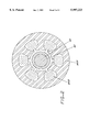
- FIG. 6 is an isometric view of the centrifugal chuck, showing the inward end of the chuck.
- FIG. 7 is a partially broken-away isometric view of the front end of the centrifugal chuck.
- FIG. 1 is a side cross-sectional view of an exemplary drilling spindle 50 embodying aspects of the present invention.
- the spindle includes a spindle housing 52, which in an exemplary embodiment is stationary in a rotational sense.
- the spindle 50 is typically mounted on an overhead beam or gantry, in the manner illustrated in U.S. Pat. No. 4,761,876.
- a work piece is positioned on a work table below the gantry, which is moved relative to the spindle by an X-Y positioning system.
- the spindle is fixed in the X-Y sense, although in other applications, it can be moved in the X-Y as well as Z directions to provide relative motion to position the spindle and the work piece and for other functions such as tool changing.
- a reciprocating spindle shaft 60 is mounted within the spindle body 52, and is rotatable, by a rotary drive system, and axially movable, by a linear drive system, to advance/retract the shaft along the spindle axis 54.
- the shaft is shown in the advanced, down position in FIG. 1.
- the shaft is fabricated of a material which is very stiff and which has significantly less diametric growth than a steel shaft at high shaft revolution rates.
- the reciprocating shaft 60 is fabricated of a ceramic material to obtain a shaft of high stiffness (high Young's modulus), relatively low weight, and low diametric growth at high revolution rates.
- An exemplary ceramic material is the product UL 600 of Coors Ceramic Company, 600 Ninth Street, Golden, Colo. 80401, which is believed to be 96% alumina, with a Young's modulus value of 44 million, and which is fabricated to produce a sintered alumina ceramic tube.
- tool steel has a typical Young's modulus value on the order of 30 million, and so the ceramic tube is much stiffer. Ceramic tubes suitable for the purpose can be fabricated by those skilled in the industrial ceramics art.
- the shaft is a hollow tube having an outer diameter of 0.7 inch, an inner diameter of 0.5 inch, and a length of 6 inches. This tube has a typical weight of 0.3 pound, in contrast to an all metal shaft which could weigh 0.75 pounds or more.
- the shaft is reciprocated along the shaft axis in the spindle through a range of 0.4 inch.
- a conventional spindle with a non-reciprocating shaft, requiring the entire spindle to be moved up/down, can weight 12-20 pounds.
- the shaft 60 is captured in two radial air bearings 70, 72.
- the first air bearing 70 is at the front (distal) end 62 of the shaft.
- the second air bearing 72 is at the back (interior) end 64 of the shaft.
- Air bearing 70 is supplied with pressurized air from an air supply connected at port 74, through passageway 70A and transverse openings including openings 70B, 70C formed in the body and extending radially about the shaft opening.
- Air bearing 72 is supplied with pressurized air from an air supply connected at port 122, through passageway 72A and transverse openings including openings 72B, 72C formed in the body and extending radially about the shaft opening.
- the radial air bearings support the shaft 60 during rotation and also allow it to move up and down along the rotating axis 54.
- the ceramic shaft 60 is a hollow tubular shaft, with a hole 62 running through its center.
- a centrifugal chuck 150 is mounted in a steel sleeve 148 attached in the front end of the shaft within the hole 62.
- the function of the sleeve is to distribute local stresses and prevent fracturing of the ceramic shaft 60.
- the sleeve can be very lightly pressed into place within the hole 62, or preferably secured in place by epoxy.
- the shaft 60 is supported for rotation at rates which can exceed 200,000 revolutions per minute.
- the shaft is driven by a rotary drive system comprising a DC permanent magnet brushless motor 80.
- the motor includes a rare earth permanent magnet 82 mounted in the middle of the shaft 60 within the hole 62, and preferably secured in place by epoxy.
- the permanent magnet DC motor 80 further includes a stator circuit 84 mounted in the bore of the spindle housing 52 between the radial air bearings 70, 72.
- the stator circuit 84 includes a plurality of stator structures 84A each having a stator winding 84B wound thereon.
- the magnet 82 has formed therein axially aligned north and south poles.
- a DC motor driver provides excitation signals to the stator windings 84B, setting up electromagnetic fields which act on the magnet 82, imparting a rotational force to the magnet and thus to the shaft.
- FIG. 2 is a schematic view illustrative of general magnetic elements of the rotary drive motor 80.
- the north and south poles of the magnet 82 are represented as N and S, respectively.
- the stator lamination structures 84A and the windings 84B are depicted schematically.
- the magnet 82 is disposed within the opening in the hollow shaft tube.
- a metal sleeve (not shown) could be used to line the inside of the shaft tube in the region in which the magnet is positioned.
- This exemplary form of motor is a 2-pole, 3-phase motor, although other types of electrical motors could alternatively be employed.
- rare earth magnet DC brushless motors are generally known in the art, as well as techniques for driving the motors.
- the placement of the magnet within a hollow spindle shaft is not known. At high rotation rates, the magnet will tend to have diametrical growth due to the high centrifugal forces exerted on the magnet during rotation. If the magnet were to be placed on the external periphery of the shaft, this diametrical growth could lead to magnet damage or seizure of the rotor.
- the ceramic shaft 60 is stiff enough to withstand the centrifugal force without a significant diametrical expansion, and to hold the magnet within the shaft opening.
- a steel thrust plate 88 is attached at the back end of the shaft 60, e.g. by epoxy.
- the plate 88 defines a flange 88A having a diameter larger than the outer diameter of the shaft 60.
- the purpose of the flange is to prevent the shaft 60 from sliding out of the spindle body.
- the flange 88A will contact the air bearing structure to provide a lower travel stop on the axial movement of the shaft.
- the spindle 50 thus comprises a shaft assembly 90 with several components, including the hollow ceramic shaft 60, the centrifugal chuck 150 for holding the drill bit, the permanent magnet 82 to provide rotation to the shaft, and the thrust plate 88.
- the thrust plate 88 accepts the Z-axis driving motion applied to the shaft 60 through a thrust bearing 100 from the linear drive system 110.
- the thrust bearing 100 includes a thrust bearing slider 104.
- the thrust bearing 100 provides the combination of a magnetically-attracted and an air-pressure-repelled thrust bearing in this embodiment to reduce the area required for the thrust bearing. This reduction in the thrust bearing area decreases the stress level in the thrust bearing flange 88A.
- the thrust plate 88 is attracted toward a magnet plate 102 installed in the forward end of the thrust bearing slider 104, and repelled at the same time by an air thrust bearing 106 built into the magnet plate 102. Air pressure between the magnet plate 102 and the thrust plate 88 creates a gap at interface 108 between these two components and allows the shaft 62 to rotate in respect to the thrust bearing slider 104 which does not rotate.
- the magnet plate 102 is a permanent magnet structure.
- the air bearing 106 is supplied by pressurized air at port 122.
- the thrust bearing slider 104 is captured in two radial air bearings 104B, 104C which keep it in position and allow up and down reciprocating motion to drive the spindle shaft 60 and the drill bit into the work piece. This motion is generated by the linear motor 110 attached to the back of the spindle.
- the drive system 110 includes a linear motor comprising a motor coil structure 112 formed in a cup-like configuration, with coil windings 112A and 112B wound about the periphery of the cup-like structure, as shown in FIGS. 1A and 1B.
- the coil structure 112 is fabricated of aluminum, and is cooled by air.
- the thrust bearing slider 104 is attached to the coil structure 112 by fasteners 104A, and is provided with an anti-rotation device which is attached to the linear motor coil 112, and interacts with the wall of linear motor adapter 114.
- the anti-rotation device is a pin 115 which slides in a slot 117 formed in the linear motor housing.
- a pair of TEFLON (TM) dowels is disposed on either side of the pin within the slot to guide the pin in the slot.
- the pin 115 extends from the coil structure which rides up/down within a slot formed in the adaptor housing.
- a linear motor magnet assembly 116 is attached by a clamping device 118 into the linear motor adapter 114, which is secured at the upper end of the spindle housing structure 52.
- the magnet assembly 116 includes an iron cylinder 116A, and iron core elements 116B, 116C supported inside the cylinder 116A, which sandwich permanent magnets 116D and 116E.
- the magnet assembly 116 is stationary, while the coil structure 112 moves axially along axis 54 within a gap between the cylinder 116A and the sandwiched iron core elements 115 and magnets 116C in response to linear motor drive signals applied to the coil windings.
- the linear motor provides an axial range of movement to the shaft of 0.4 inch, although other applications may require different movement ranges.
- the excitation drive signals to the linear motor are provided on a set of leads 119 which are coupled to the linear motor driver.
- Air to all air bearings is distributed to fittings at port 122. Cooling water is also distributed through input fitting 124, into the spindle body and output through output fitting 126, and is routed within passageways 128 within the spindle body around the air bearings end to the DC permanent magnet brushless motor 80 to keep the spindle at constant temperature.
- FIG. 3 is a functional block diagram of the spindle 50 and the ancillary system elements for operating the spindle.
- These ancillary elements include a controller/motor driver system 30 which generates the motor drive signals for the rotary drive motor 80 and for the linear drive motor 110.
- a pressurized air supply 32 is connected to the spindle housing to supply the air bearings.
- a recirculating coolant supply is also connected to the spindle housing to circulate a liquid coolant through the spindle housing.
- the centrifugal chuck 150 is illustrated in further detail in FIGS. 4-7.
- the centrifugal chuck 150 holds the drill bit 10 in place during drilling operations, and is designed to provide the capability to grip the drill shank 12 at two points 152, 154 which are separated along the axis of rotation of the tool shank. Engaging the shank at two points guarantees parallelism of the shank to the axis of rotation.
- the chuck 150 is designed in the form of a uni-body flexure which has two gripping segments 160 and 170, the first 160 at the front and the second 170 at the back of the chuck 150.
- Each gripping segment includes four weights which are joined by flexures to form a uni-body construction.
- the first gripping segment 160 includes four weights 162A, 162B, 162C and 162D which are joined adjacent a gripping end by flexures 164A, 164B, 164C and 164D.
- the second gripping segment 170 includes four weights 172A, 172B, 172C and 172D which are joined by flexures 174A, 174B, 174C and 174D.
- the joining flexures are disposed well away from the longitudinal center of mass of the respective weights, permitting movement of the weights in a pivoting action in response to centrifugal forces.
- the front and back gripping segments are connected with each other by four thin wall flexures 180A, 180B, 180C and 180D.
- Each weight when exposed to the spindle rotation, is subjected to centrifugal force which moves it outward. It then rotates around a pivot point defined by a ring of metal protruding from the flexures joining the four weights of each gripping segment, and rests against the interior sleeve 148 fitted into the bore in the spindle shaft.
- the gripping end of the weight is closing on the shank 12 of the drill bit 10 to apply force on the drill shaft to provide the drilling torque for the drill bit and to overcome drill bit resistance when entering the material.
- weight 162A has a weighted end 162A1 and a gripping end 162A2.
- the weighted end 162A1 moves outwardly in response to centrifugal force, pivoting about the ring 165 at flexures 164A, 164B to apply leverage force to move gripping end 162A2 inwardly against the shank 12.
- the ring surface protrudes slightly, by a few thousandths of an inch, from the exterior surface of the chuck.
- exemplary weight 172C (FIG. 6) has a weighted end 172C1 and a gripping end 172C2.
- the weighted end 172C1 moves outwardly in response to centrifugal force, pivoting about the ring 175 flexures 174C, 174D to apply leverage force to move gripping end 172C2 inwardly against the shank 12.
- the other weights operate in a similar fashion.
- the chuck is fabricated from a block of tool steel, which is machined to produce the uni-body chuck structure.
- a rubber O-ring 192 is installed into a groove 194 of the front segment of the chuck to frictionally engage the shank 12, which keeps the drill bit in the centrifugal chuck when it is not rotating.
- the front ring 165 has a slightly larger outer diameter (by, e.g., 1 inch) than the outer diameter of the ring 175, and is pressed into the sleeve 148.
- the back segment of the chuck, at ring 175, has a slip fit into the sleeve 148 to allow it to float in the bore when actuated.
- Behind the chuck 150 is a disk 200 with a threaded hole in the center which allows chuck removal without damage.
- the front segment 160 of the chuck 150 is pressed into the sleeve in the spindle shaft and the bore of the chuck is ground on the assembly to guarantee concentricity of the drill shank with the axis of rotation.
- the front of the chuck is secured by a wire ring 196 (FIG. 1) located in a groove 198, which prevents the chuck from being forced out of the spindle nose.
- the chuck can be removed from the rotor shaft by inserting a threaded shaft into the chuck and threading it into the chuck removal disk and then applying force outwardly to the shaft.
- the disk in that condition is applying force to the chuck and forces it out of the bore of the spindle shaft.
- the grip on the drill shank is increasing with the increase of the rpm and it is strongest on the highest rpm.
- the grip on the drill shank is adequate to be able to rout with 0.062 diameter router in a three high stack of boards each 0.062 thick.
Abstract
Description
Claims (34)
Priority Applications (5)
| Application Number | Priority Date | Filing Date | Title |
|---|---|---|---|
| US09/158,385 US5997223A (en) | 1998-09-22 | 1998-09-22 | High speed drilling spindle with reciprocating ceramic shaft and edoubl-gripping centrifugal chuck |
| EP04077201A EP1475184A3 (en) | 1998-09-22 | 1999-09-10 | High speed drilling spindle with reciprocating ceramic shaft and double-gripping centrifugal chuck |
| EP99307175A EP0997226B1 (en) | 1998-09-22 | 1999-09-10 | High speed drilling spindle with reciprocating ceramic shaft and double-gripping centrifugal chuck |
| DE69928895T DE69928895T2 (en) | 1998-09-22 | 1999-09-10 | High-speed drilling spindle with a reciprocating ceramic shaft and a double-grip centrifugal chuck |
| US09/436,817 US6227777B1 (en) | 1998-09-22 | 1999-11-09 | High speed drilling spindle with reciprocating shaft and double-gripping centrifugal chuck |
Applications Claiming Priority (1)
| Application Number | Priority Date | Filing Date | Title |
|---|---|---|---|
| US09/158,385 US5997223A (en) | 1998-09-22 | 1998-09-22 | High speed drilling spindle with reciprocating ceramic shaft and edoubl-gripping centrifugal chuck |
Related Child Applications (1)
| Application Number | Title | Priority Date | Filing Date |
|---|---|---|---|
| US09/436,817 Continuation US6227777B1 (en) | 1998-09-22 | 1999-11-09 | High speed drilling spindle with reciprocating shaft and double-gripping centrifugal chuck |
Publications (1)
| Publication Number | Publication Date |
|---|---|
| US5997223A true US5997223A (en) | 1999-12-07 |
Family
ID=22567873
Family Applications (2)
| Application Number | Title | Priority Date | Filing Date |
|---|---|---|---|
| US09/158,385 Expired - Fee Related US5997223A (en) | 1998-09-22 | 1998-09-22 | High speed drilling spindle with reciprocating ceramic shaft and edoubl-gripping centrifugal chuck |
| US09/436,817 Expired - Fee Related US6227777B1 (en) | 1998-09-22 | 1999-11-09 | High speed drilling spindle with reciprocating shaft and double-gripping centrifugal chuck |
Family Applications After (1)
| Application Number | Title | Priority Date | Filing Date |
|---|---|---|---|
| US09/436,817 Expired - Fee Related US6227777B1 (en) | 1998-09-22 | 1999-11-09 | High speed drilling spindle with reciprocating shaft and double-gripping centrifugal chuck |
Country Status (3)
| Country | Link |
|---|---|
| US (2) | US5997223A (en) |
| EP (2) | EP0997226B1 (en) |
| DE (1) | DE69928895T2 (en) |
Cited By (35)
| Publication number | Priority date | Publication date | Assignee | Title |
|---|---|---|---|---|
| US6204585B1 (en) | 1997-12-19 | 2001-03-20 | Riello Macchine Transfer Srl | Work unit having an integrally mounted drive unit |
| US6216798B1 (en) * | 1997-12-19 | 2001-04-17 | Riello Macchine Transfer Srl | Work unit for machine tool, with linear electric motor for axial movement of the spindle |
| US6227777B1 (en) * | 1998-09-22 | 2001-05-08 | Electro Scientific Industries, Inc. | High speed drilling spindle with reciprocating shaft and double-gripping centrifugal chuck |
| US6256121B1 (en) | 1999-10-08 | 2001-07-03 | Nanovia, Lp | Apparatus for ablating high-density array of vias or indentation in surface of object |
| US6280124B1 (en) * | 1999-03-18 | 2001-08-28 | Ballado Investments Inc. | Spindle with linear motor for axially moving a tool |
| US6310701B1 (en) | 1999-10-08 | 2001-10-30 | Nanovia Lp | Method and apparatus for ablating high-density array of vias or indentation in surface of object |
| US6420675B1 (en) | 1999-10-08 | 2002-07-16 | Nanovia, Lp | Control system for ablating high-density array of vias or indentation in surface of object |
| US20030014895A1 (en) * | 1999-10-08 | 2003-01-23 | Lizotte Todd E. | Control system for ablating high-density array of vias or indentation in surface of object |
| US20030061921A1 (en) * | 2001-09-28 | 2003-04-03 | Industrial Technology Research Institute | Internal, active, and compensatory method and device for the rotational main-shaft of a cutting tool with axial bias-and-swing |
| US6585462B1 (en) * | 1999-11-10 | 2003-07-01 | Skf Nova Ab | Device in a tool holding assembly for moving a rotatable shaft in the axial direction |
| US6653593B2 (en) | 1999-10-08 | 2003-11-25 | Nanovia, Lp | Control system for ablating high-density array of vias or indentation in surface of object |
| US6675549B1 (en) * | 2000-10-04 | 2004-01-13 | Makino Milling Machine Co., Ltd | Processing machine installation |
| GB2391498A (en) * | 2002-08-09 | 2004-02-11 | Hitachi Via Mechanics Ltd | Spindle unit with spindle supported internally and externally with gas bearings |
| WO2004058448A2 (en) * | 2002-12-27 | 2004-07-15 | Index-Werke Gmbh & Co. Kg Hahn & Tessky | Drive unit |
| US20040210874A1 (en) * | 2003-01-21 | 2004-10-21 | Naohiro Kageyama | Automatic test program generation method |
| US20040217173A1 (en) * | 2003-05-01 | 2004-11-04 | Lizotte Todd E | Method and apparatus for reading firearm microstamping |
| US6833911B2 (en) | 1999-10-08 | 2004-12-21 | Identification Dynamics, Inc. | Method and apparatus for reading firearm microstamping |
| US20050241203A1 (en) * | 2003-05-01 | 2005-11-03 | Lizotte Todd E | Method and apparatus for cartridge identification imprinting in difficult contexts by recess protected indicia |
| US20060075683A1 (en) * | 2001-04-04 | 2006-04-13 | Klein Dennis J | Apparatus and method for the conversion of water into a new gaseous and combustible form and the combustible gas formed thereby |
| US20060174531A1 (en) * | 1999-10-08 | 2006-08-10 | Lizotte Todd E | Method and apparatus for reading firearm microstamping |
| US20070107574A1 (en) * | 2004-05-27 | 2007-05-17 | Trumpf Werkzeugmaschinen Gmbh + Co. Kg | Spindle drive support |
| US20070151846A1 (en) * | 2001-04-04 | 2007-07-05 | Hydrogen Technology Applications, Inc. | Apparatus and method for the conversion of water into a clean burning combustible gas for use as an additive with other forms of fuels |
| US7547168B1 (en) | 2008-04-17 | 2009-06-16 | Kosmowski Wojciech B | High speed spindle system and centrifugal chuck |
| US20110200386A1 (en) * | 2008-10-23 | 2011-08-18 | Maarten Hartger Kimman | Rotary connector for a rotating shank or axle |
| US20120262259A1 (en) * | 2009-10-14 | 2012-10-18 | Tat Joo Teo | linear-rotary electromagnetic actuator |
| US20130181548A1 (en) * | 2010-09-21 | 2013-07-18 | Kayaba Industry Co., Ltd. | Linear actuator |
| US8961019B2 (en) | 2011-05-10 | 2015-02-24 | Smith International, Inc. | Flow control through thrust bearing assembly |
| US20150072037A1 (en) * | 2013-09-12 | 2015-03-12 | Sino-Alloy Machinery Inc. | Cutter blade drivinga nd positioning control structure for plastic pelletizing machine |
| CN104526004A (en) * | 2014-12-23 | 2015-04-22 | 周大胜 | Movable type hole drilling device |
| US20150115848A1 (en) * | 2013-10-28 | 2015-04-30 | Iris Dynamics Ltd. | Electric linear actuator |
| US9050664B1 (en) * | 2014-06-13 | 2015-06-09 | Interdyne Systems Inc | Low mass, low profile, force balanced Z-axis drilling apparatus with improved machine dynamics |
| US9050661B1 (en) * | 2014-06-13 | 2015-06-09 | Interdyne Systems Inc | Centrifugal collet for high speed operation |
| WO2016162483A3 (en) * | 2015-04-08 | 2016-12-08 | Lti Motion Gmbh | Tool drive having a spindle shaft and operating method |
| GB2567307A (en) * | 2017-09-14 | 2019-04-10 | Spirit Aerosys Inc | Apparatus and method for minimizing elongation in drilled holes |
| GB2588160A (en) * | 2019-10-10 | 2021-04-21 | Univ Brunel | Adaptive precision chuck |
Families Citing this family (26)
| Publication number | Priority date | Publication date | Assignee | Title |
|---|---|---|---|---|
| TW434363B (en) * | 1999-10-22 | 2001-05-16 | Mitsubishi Materials Corp | High speed drilling apparatus and method |
| US6611074B2 (en) * | 2001-04-12 | 2003-08-26 | Ballado Investments Inc. | Array of electromagnetic motors for moving a tool-carrying sleeve |
| JP4471531B2 (en) * | 2001-05-16 | 2010-06-02 | シチズンホールディングス株式会社 | Material gripping device and automatic lathe |
| TWI285243B (en) * | 2002-03-20 | 2007-08-11 | Ntn Toyo Bearing Co Ltd | Cylindrical roller bearing |
| US7198438B2 (en) * | 2003-04-11 | 2007-04-03 | Kosmowski Wojciech B | Drilling system with stationary work table |
| US20050097717A1 (en) * | 2003-11-06 | 2005-05-12 | Bret Rasmussen | Machining tool |
| US7105956B2 (en) * | 2004-04-23 | 2006-09-12 | Aerotech, Inc. | High precision z-theta stage |
| US7025542B2 (en) * | 2004-07-06 | 2006-04-11 | Honda Motor Co., Ltd. | Guide device for workpiece machining head, machine having the same, and guide method |
| JP4840897B2 (en) * | 2004-10-20 | 2011-12-21 | 日立ビアメカニクス株式会社 | Tool positioning device and processing member |
| ITBO20040658A1 (en) * | 2004-10-22 | 2005-01-22 | Jobs Spa | MACHINING HEAD FOR MACHINE TOOLS |
| DE102005003701B4 (en) * | 2005-01-26 | 2008-08-07 | Aerolas Gmbh, Aerostatische Lager- Lasertechnik | Clamping device for a rotary body |
| GB0609180D0 (en) * | 2006-05-09 | 2006-06-21 | Gsi Group Ltd | Tool holder spindles |
| DE102006032189A1 (en) * | 2006-07-12 | 2008-01-17 | Ima Klessmann Gmbh Holzbearbeitungssysteme | Spindle unit for a multi-spindle drilling unit |
| WO2008015454A1 (en) * | 2006-08-03 | 2008-02-07 | Gsi Group Limited | Tool holder assemblies |
| GB2461011B (en) * | 2007-11-06 | 2011-10-05 | Gsi Group Ltd | Motor spindles and shaft assemblies for motor spindles |
| US9447823B2 (en) | 2008-10-23 | 2016-09-20 | Micro Turbine Technology Bv | Rotary connector for a rotating shank or axle |
| US8601927B2 (en) * | 2009-11-30 | 2013-12-10 | Geiss Ag | Device for ultrasonic machining, machine tool and machine tool apparatus |
| DE102010028872A1 (en) * | 2010-05-11 | 2011-11-17 | Siemens Aktiengesellschaft | Drive device for rotary and linear movements with decoupled inertia |
| DE102011003400A1 (en) | 2011-01-31 | 2012-08-02 | Ate Antriebstechnik Und Entwicklungs Gmbh | electric motor |
| US8899887B2 (en) * | 2013-02-13 | 2014-12-02 | Interdyne Systems Inc. | Drilling apparatus with a decoupled force frame and metrology frame for enhanced positioning |
| DE102014105652A1 (en) * | 2014-04-22 | 2015-10-22 | Föhrenbach GmbH | Centrifugal clamping system |
| DE102014109661B4 (en) * | 2014-07-10 | 2021-12-30 | Föhrenbach GmbH | High frequency drilling spindle |
| DE102016200299A1 (en) * | 2015-01-14 | 2016-07-14 | Aktiebolaget Skf | Motor spindle and method for moving a shaft of a motor spindle |
| DE102015101882A1 (en) * | 2015-02-10 | 2016-08-11 | Schenck Rotec Gmbh | Rotor for an electric motor |
| CN107820361B (en) * | 2017-10-11 | 2020-07-24 | 龙南骏亚电子科技有限公司 | Preparation method of ceramic-based circuit board |
| US11612941B2 (en) | 2021-02-05 | 2023-03-28 | Eltool Corporation | Speeder device for increasing the speed of a workpiece |
Citations (25)
| Publication number | Priority date | Publication date | Assignee | Title |
|---|---|---|---|---|
| US2310990A (en) * | 1940-08-29 | 1943-02-16 | Sullivan Machinery Co | Drilling apparatus |
| US2954674A (en) * | 1958-08-11 | 1960-10-04 | Ekwall Corp | Centrifugal feed unit |
| DE1552197A1 (en) * | 1965-07-01 | 1969-10-23 | Davis Gilbert Colin | Chuck for rotating tools |
| DE2047311A1 (en) * | 1969-09-27 | 1971-09-09 | Toyoda Koki K K , Kanya, Aichi (Japan) | Spindle head |
| US3687467A (en) * | 1970-05-01 | 1972-08-29 | Digital Telephone Systems Inc | Collet |
| US3700250A (en) * | 1970-12-01 | 1972-10-24 | Continental Can Co | Gripping type compound applying chuck assembly |
| US4017203A (en) * | 1976-04-14 | 1977-04-12 | Marantette William F | High speed drill system |
| DE2624644A1 (en) * | 1971-04-21 | 1977-12-15 | Scheer & Cie C F | Woodworking drill with drive motor in housing - has central hollow motor shaft containing axially movable working spindle for drill |
| US4088417A (en) * | 1977-03-04 | 1978-05-09 | Advanced Controls Corp. | Method and apparatus for high speed, high precision drilling and machining |
| US4095855A (en) * | 1976-09-20 | 1978-06-20 | Fox International, Inc. | Gas lubricated spindle bearing assembly |
| US4135847A (en) * | 1977-08-29 | 1979-01-23 | Tulon, Inc. | Composite drill for drilling circuit boards |
| US4191385A (en) * | 1979-05-15 | 1980-03-04 | Fox Wayne L | Vacuum-sealed gas-bearing assembly |
| US4520551A (en) * | 1982-09-01 | 1985-06-04 | Posalux S.A. | Machine tool |
| US4596067A (en) * | 1983-02-17 | 1986-06-24 | Prt Pluritec Italia S.P.A. | Drilling machine for boards, particularly of printed circuits |
| US4654956A (en) * | 1985-04-16 | 1987-04-07 | Protocad, Inc. | Drill apparatus for use with computer controlled plotter |
| US4761876A (en) * | 1986-04-18 | 1988-08-09 | Dynamotion Corporation | High speed precision drilling system |
| US4869626A (en) * | 1986-04-18 | 1989-09-26 | Dynamotion Corporation | High speed drilling spindle |
| US4957398A (en) * | 1987-04-30 | 1990-09-18 | Friedrich Deckel Aktiengesellschaft | Two-section tool spindle having a channel for carrying pressurized fluid |
| US5009554A (en) * | 1989-09-09 | 1991-04-23 | Brother Kogyo Kabushiki Kaisha | Machine tool |
| US5068958A (en) * | 1990-09-18 | 1991-12-03 | Dynamotion Corporation | Method and apparatus for changing tools in an automated machine tool |
| US5145298A (en) * | 1989-09-11 | 1992-09-08 | Optima Industries, Inc. | High speed drill spindle |
| US5230685A (en) * | 1990-09-28 | 1993-07-27 | Posalux S.A. | Machine tool for machining printed circuit boards |
| US5350263A (en) * | 1992-03-30 | 1994-09-27 | Gifam S.R.L. | Toolhead for chip-forming machine tools |
| US5518346A (en) * | 1994-07-21 | 1996-05-21 | Geise; Samuel C. | High-speed hydrodynamic spindle and method for machining composite and specialized metallic materials |
| US5529441A (en) * | 1994-02-28 | 1996-06-25 | Cybernetics Products, Inc. | Drill coordinate optimization for multi-layer printed circuit board |
Family Cites Families (7)
| Publication number | Priority date | Publication date | Assignee | Title |
|---|---|---|---|---|
| DE4009461A1 (en) * | 1989-09-08 | 1991-03-21 | Toshiba Machine Co Ltd | SPINDLE FOR A TOOL MACHINE |
| DE69101976T2 (en) * | 1990-01-08 | 1994-09-01 | Mori Seiki Seisakusho Kk | Spindle unit for machine tools. |
| DE4025610A1 (en) * | 1990-08-13 | 1992-02-20 | Fortuna Werke Maschf Ag | HIGH-SPEED DRILLING OR MILLING SPINDLE |
| GB2270724B (en) * | 1992-09-19 | 1995-08-09 | Systematic Drill Head Co Ltd | Machine tools |
| US5674032A (en) * | 1995-10-12 | 1997-10-07 | Aesop, Inc. | Tooling system and method with integral hydrostatic bearings and turbine power source |
| JPH10277803A (en) * | 1997-03-28 | 1998-10-20 | Sodick Co Ltd | Spindle and spindle device of machine tool |
| US5997223A (en) * | 1998-09-22 | 1999-12-07 | Electro Scientific Industries, Inc. | High speed drilling spindle with reciprocating ceramic shaft and edoubl-gripping centrifugal chuck |
-
1998
- 1998-09-22 US US09/158,385 patent/US5997223A/en not_active Expired - Fee Related
-
1999
- 1999-09-10 DE DE69928895T patent/DE69928895T2/en not_active Expired - Lifetime
- 1999-09-10 EP EP99307175A patent/EP0997226B1/en not_active Expired - Lifetime
- 1999-09-10 EP EP04077201A patent/EP1475184A3/en not_active Withdrawn
- 1999-11-09 US US09/436,817 patent/US6227777B1/en not_active Expired - Fee Related
Patent Citations (26)
| Publication number | Priority date | Publication date | Assignee | Title |
|---|---|---|---|---|
| US2310990A (en) * | 1940-08-29 | 1943-02-16 | Sullivan Machinery Co | Drilling apparatus |
| US2954674A (en) * | 1958-08-11 | 1960-10-04 | Ekwall Corp | Centrifugal feed unit |
| DE1552197A1 (en) * | 1965-07-01 | 1969-10-23 | Davis Gilbert Colin | Chuck for rotating tools |
| DE2047311A1 (en) * | 1969-09-27 | 1971-09-09 | Toyoda Koki K K , Kanya, Aichi (Japan) | Spindle head |
| US3687467A (en) * | 1970-05-01 | 1972-08-29 | Digital Telephone Systems Inc | Collet |
| US3700250A (en) * | 1970-12-01 | 1972-10-24 | Continental Can Co | Gripping type compound applying chuck assembly |
| DE2624644A1 (en) * | 1971-04-21 | 1977-12-15 | Scheer & Cie C F | Woodworking drill with drive motor in housing - has central hollow motor shaft containing axially movable working spindle for drill |
| US4017203A (en) * | 1976-04-14 | 1977-04-12 | Marantette William F | High speed drill system |
| US4095855A (en) * | 1976-09-20 | 1978-06-20 | Fox International, Inc. | Gas lubricated spindle bearing assembly |
| US4088417A (en) * | 1977-03-04 | 1978-05-09 | Advanced Controls Corp. | Method and apparatus for high speed, high precision drilling and machining |
| US4135847A (en) * | 1977-08-29 | 1979-01-23 | Tulon, Inc. | Composite drill for drilling circuit boards |
| US4191385A (en) * | 1979-05-15 | 1980-03-04 | Fox Wayne L | Vacuum-sealed gas-bearing assembly |
| US4520551A (en) * | 1982-09-01 | 1985-06-04 | Posalux S.A. | Machine tool |
| US4520551B1 (en) * | 1982-09-01 | 1987-10-13 | ||
| US4596067A (en) * | 1983-02-17 | 1986-06-24 | Prt Pluritec Italia S.P.A. | Drilling machine for boards, particularly of printed circuits |
| US4654956A (en) * | 1985-04-16 | 1987-04-07 | Protocad, Inc. | Drill apparatus for use with computer controlled plotter |
| US4761876A (en) * | 1986-04-18 | 1988-08-09 | Dynamotion Corporation | High speed precision drilling system |
| US4869626A (en) * | 1986-04-18 | 1989-09-26 | Dynamotion Corporation | High speed drilling spindle |
| US4957398A (en) * | 1987-04-30 | 1990-09-18 | Friedrich Deckel Aktiengesellschaft | Two-section tool spindle having a channel for carrying pressurized fluid |
| US5009554A (en) * | 1989-09-09 | 1991-04-23 | Brother Kogyo Kabushiki Kaisha | Machine tool |
| US5145298A (en) * | 1989-09-11 | 1992-09-08 | Optima Industries, Inc. | High speed drill spindle |
| US5068958A (en) * | 1990-09-18 | 1991-12-03 | Dynamotion Corporation | Method and apparatus for changing tools in an automated machine tool |
| US5230685A (en) * | 1990-09-28 | 1993-07-27 | Posalux S.A. | Machine tool for machining printed circuit boards |
| US5350263A (en) * | 1992-03-30 | 1994-09-27 | Gifam S.R.L. | Toolhead for chip-forming machine tools |
| US5529441A (en) * | 1994-02-28 | 1996-06-25 | Cybernetics Products, Inc. | Drill coordinate optimization for multi-layer printed circuit board |
| US5518346A (en) * | 1994-07-21 | 1996-05-21 | Geise; Samuel C. | High-speed hydrodynamic spindle and method for machining composite and specialized metallic materials |
Non-Patent Citations (2)
| Title |
|---|
| Japanese Patent Abstract, vol. 6, No. 14(M 108) (892), Jan. 27, 1982 JP 56 134109 , T. Hori. * |
| Japanese Patent Abstract, vol. 6, No. 14(M-108) (892), Jan. 27, 1982 [JP 56-134109], T. Hori. |
Cited By (55)
| Publication number | Priority date | Publication date | Assignee | Title |
|---|---|---|---|---|
| US6216798B1 (en) * | 1997-12-19 | 2001-04-17 | Riello Macchine Transfer Srl | Work unit for machine tool, with linear electric motor for axial movement of the spindle |
| US6204585B1 (en) | 1997-12-19 | 2001-03-20 | Riello Macchine Transfer Srl | Work unit having an integrally mounted drive unit |
| US6227777B1 (en) * | 1998-09-22 | 2001-05-08 | Electro Scientific Industries, Inc. | High speed drilling spindle with reciprocating shaft and double-gripping centrifugal chuck |
| US6280124B1 (en) * | 1999-03-18 | 2001-08-28 | Ballado Investments Inc. | Spindle with linear motor for axially moving a tool |
| US6653593B2 (en) | 1999-10-08 | 2003-11-25 | Nanovia, Lp | Control system for ablating high-density array of vias or indentation in surface of object |
| US6833911B2 (en) | 1999-10-08 | 2004-12-21 | Identification Dynamics, Inc. | Method and apparatus for reading firearm microstamping |
| US6420675B1 (en) | 1999-10-08 | 2002-07-16 | Nanovia, Lp | Control system for ablating high-density array of vias or indentation in surface of object |
| US20030014895A1 (en) * | 1999-10-08 | 2003-01-23 | Lizotte Todd E. | Control system for ablating high-density array of vias or indentation in surface of object |
| US20060174531A1 (en) * | 1999-10-08 | 2006-08-10 | Lizotte Todd E | Method and apparatus for reading firearm microstamping |
| US6886284B2 (en) | 1999-10-08 | 2005-05-03 | Identification Dynamics, Llc | Firearm microstamping and micromarking insert for stamping a firearm identification code and serial number into cartridge shell casings and projectiles |
| US6310701B1 (en) | 1999-10-08 | 2001-10-30 | Nanovia Lp | Method and apparatus for ablating high-density array of vias or indentation in surface of object |
| US7111423B2 (en) | 1999-10-08 | 2006-09-26 | Identification Dynamics, Llc | Method and apparatus for reading firearm microstamping |
| US6256121B1 (en) | 1999-10-08 | 2001-07-03 | Nanovia, Lp | Apparatus for ablating high-density array of vias or indentation in surface of object |
| US6585462B1 (en) * | 1999-11-10 | 2003-07-01 | Skf Nova Ab | Device in a tool holding assembly for moving a rotatable shaft in the axial direction |
| US6675549B1 (en) * | 2000-10-04 | 2004-01-13 | Makino Milling Machine Co., Ltd | Processing machine installation |
| US20070151846A1 (en) * | 2001-04-04 | 2007-07-05 | Hydrogen Technology Applications, Inc. | Apparatus and method for the conversion of water into a clean burning combustible gas for use as an additive with other forms of fuels |
| US20070080070A1 (en) * | 2001-04-04 | 2007-04-12 | Klein Dennis J | Apparatus and method for the conversion of water into a new gaseous and combustible form and the combustible gas formed thereby |
| US20060075683A1 (en) * | 2001-04-04 | 2006-04-13 | Klein Dennis J | Apparatus and method for the conversion of water into a new gaseous and combustible form and the combustible gas formed thereby |
| US6910839B2 (en) * | 2001-09-28 | 2005-06-28 | Industrial Technology Research Institute | Internal, active, and compensatory method and device for the rotational main-shaft of a cutting tool with axial bias-and-swing |
| US20030061921A1 (en) * | 2001-09-28 | 2003-04-03 | Industrial Technology Research Institute | Internal, active, and compensatory method and device for the rotational main-shaft of a cutting tool with axial bias-and-swing |
| GB2391498A (en) * | 2002-08-09 | 2004-02-11 | Hitachi Via Mechanics Ltd | Spindle unit with spindle supported internally and externally with gas bearings |
| GB2391498B (en) * | 2002-08-09 | 2005-06-08 | Hitachi Via Mechanics Ltd | Spindle unit |
| WO2004058448A2 (en) * | 2002-12-27 | 2004-07-15 | Index-Werke Gmbh & Co. Kg Hahn & Tessky | Drive unit |
| WO2004058448A3 (en) * | 2002-12-27 | 2004-09-16 | Index Werke Kg Hahn & Tessky | Drive unit |
| US7363614B2 (en) | 2003-01-21 | 2008-04-22 | Hitachi, Ltd. | Automatic test program generation method |
| US20040210874A1 (en) * | 2003-01-21 | 2004-10-21 | Naohiro Kageyama | Automatic test program generation method |
| US20050241203A1 (en) * | 2003-05-01 | 2005-11-03 | Lizotte Todd E | Method and apparatus for cartridge identification imprinting in difficult contexts by recess protected indicia |
| US20050188576A1 (en) * | 2003-05-01 | 2005-09-01 | Lizotte Todd E. | Method and apparatus for reading firearm microstamping |
| US20040217173A1 (en) * | 2003-05-01 | 2004-11-04 | Lizotte Todd E | Method and apparatus for reading firearm microstamping |
| US7204419B2 (en) | 2003-05-01 | 2007-04-17 | Identifcation Dynamics, Llc | Method and apparatus for reading firearm microstamping |
| US20060026880A1 (en) * | 2003-05-01 | 2006-02-09 | Lizotte Todd E | Method and apparatus for reading firearm microstamping |
| US7694616B2 (en) * | 2004-05-27 | 2010-04-13 | Trumpf Werkzeugmaschinen Gmbh + Co. Kg | Spindle drive support |
| US20070107574A1 (en) * | 2004-05-27 | 2007-05-17 | Trumpf Werkzeugmaschinen Gmbh + Co. Kg | Spindle drive support |
| US7547168B1 (en) | 2008-04-17 | 2009-06-16 | Kosmowski Wojciech B | High speed spindle system and centrifugal chuck |
| US20110200386A1 (en) * | 2008-10-23 | 2011-08-18 | Maarten Hartger Kimman | Rotary connector for a rotating shank or axle |
| US20120262259A1 (en) * | 2009-10-14 | 2012-10-18 | Tat Joo Teo | linear-rotary electromagnetic actuator |
| US20130181548A1 (en) * | 2010-09-21 | 2013-07-18 | Kayaba Industry Co., Ltd. | Linear actuator |
| US9197113B2 (en) * | 2010-09-21 | 2015-11-24 | Kayaba Industry Co., Ltd. | Linear actuator |
| US8961019B2 (en) | 2011-05-10 | 2015-02-24 | Smith International, Inc. | Flow control through thrust bearing assembly |
| US9266256B2 (en) * | 2013-09-12 | 2016-02-23 | Sino-Alloy Machinery Inc. | Cutter blade driving and positioning control structure for plastic pelletizing machine |
| US20150072037A1 (en) * | 2013-09-12 | 2015-03-12 | Sino-Alloy Machinery Inc. | Cutter blade drivinga nd positioning control structure for plastic pelletizing machine |
| US20150115848A1 (en) * | 2013-10-28 | 2015-04-30 | Iris Dynamics Ltd. | Electric linear actuator |
| US9050664B1 (en) * | 2014-06-13 | 2015-06-09 | Interdyne Systems Inc | Low mass, low profile, force balanced Z-axis drilling apparatus with improved machine dynamics |
| US9050661B1 (en) * | 2014-06-13 | 2015-06-09 | Interdyne Systems Inc | Centrifugal collet for high speed operation |
| CN104526004A (en) * | 2014-12-23 | 2015-04-22 | 周大胜 | Movable type hole drilling device |
| WO2016162483A3 (en) * | 2015-04-08 | 2016-12-08 | Lti Motion Gmbh | Tool drive having a spindle shaft and operating method |
| CN107530853A (en) * | 2015-04-08 | 2018-01-02 | Lti运动有限公司 | Cutter drives machine and operating method with main shaft axostylus axostyle |
| CN111215947A (en) * | 2015-04-08 | 2020-06-02 | 科控工业自动化德国有限公司 | Tool drive with spindle shaft and method of operation |
| CN107530853B (en) * | 2015-04-08 | 2020-07-17 | 科控工业自动化德国有限公司 | Tool drive with spindle shaft and method of operation |
| US10744606B2 (en) | 2015-04-08 | 2020-08-18 | Keba Industrial Automation Germany Gmbh | Tool drive having a spindle shaft and operating method |
| CN111215947B (en) * | 2015-04-08 | 2022-02-11 | 科控工业自动化德国有限公司 | Tool drive with spindle shaft and method of operation |
| GB2567307A (en) * | 2017-09-14 | 2019-04-10 | Spirit Aerosys Inc | Apparatus and method for minimizing elongation in drilled holes |
| GB2588160A (en) * | 2019-10-10 | 2021-04-21 | Univ Brunel | Adaptive precision chuck |
| GB2588160B (en) * | 2019-10-10 | 2022-09-21 | Univ Brunel | Adaptive precision chuck |
| US11511355B2 (en) * | 2019-10-10 | 2022-11-29 | Brunel University London | Adaptive precision chuck |
Also Published As
| Publication number | Publication date |
|---|---|
| EP1475184A3 (en) | 2005-01-05 |
| US6227777B1 (en) | 2001-05-08 |
| DE69928895D1 (en) | 2006-01-19 |
| EP1475184A2 (en) | 2004-11-10 |
| EP0997226A2 (en) | 2000-05-03 |
| EP0997226A3 (en) | 2001-12-05 |
| DE69928895T2 (en) | 2006-07-06 |
| EP0997226B1 (en) | 2005-12-14 |
Similar Documents
| Publication | Publication Date | Title |
|---|---|---|
| US5997223A (en) | High speed drilling spindle with reciprocating ceramic shaft and edoubl-gripping centrifugal chuck | |
| US7547168B1 (en) | High speed spindle system and centrifugal chuck | |
| US4869626A (en) | High speed drilling spindle | |
| US4761876A (en) | High speed precision drilling system | |
| US4922603A (en) | Drilling tool for very small diameter openings and container therefor | |
| US6611074B2 (en) | Array of electromagnetic motors for moving a tool-carrying sleeve | |
| US5078558A (en) | Low mass spindle and Z-axis unit | |
| EP1100187B1 (en) | Coreless AC induction motor | |
| JPH04250904A (en) | High speed boring rod or milling main shaft | |
| EP1100186A2 (en) | Polymer composite squirrel cage rotor with high magnetic permeability filler for induction motor and method of making it | |
| EP3733331B1 (en) | Main spindle device | |
| US4836723A (en) | Spindle assembly | |
| US3687467A (en) | Collet | |
| CN109843501A (en) | Electric machine main shaft | |
| US4664572A (en) | Chip disposer | |
| JP4319479B2 (en) | Spindle device | |
| US3795455A (en) | Machine tool having centrifugally actuated collet | |
| KR102003799B1 (en) | Air bearing spindle | |
| JPH0241884A (en) | Changing device for automatic hand of robot | |
| RU2400331C1 (en) | Spindle with centering clamping socket | |
| WO2004008613A1 (en) | Linear and rotory motors for moving a tool-carrying sleeve | |
| JPH06270004A (en) | Main spindle tool fixing/releasing mechanism | |
| SU1140887A1 (en) | Device for machining thin-walled cylindrical components | |
| EP2183069B1 (en) | Rotary tool holder assemblies | |
| CN2379236Y (en) | Apparatus for automatically changing drilling bit |
Legal Events
| Date | Code | Title | Description |
|---|---|---|---|
| AS | Assignment |
Owner name: ELECTRO SCIENTIFIC INDUSTRIES, INC., OREGON Free format text: ASSIGNMENT OF ASSIGNORS INTEREST;ASSIGNOR:KOSMOWSKI, WOJCIECH B.;REEL/FRAME:010318/0602 Effective date: 19981117 |
|
| REMI | Maintenance fee reminder mailed | ||
| FPAY | Fee payment |
Year of fee payment: 4 |
|
| SULP | Surcharge for late payment | ||
| FEPP | Fee payment procedure |
Free format text: PAYOR NUMBER ASSIGNED (ORIGINAL EVENT CODE: ASPN); ENTITY STATUS OF PATENT OWNER: LARGE ENTITY |
|
| AS | Assignment |
Owner name: WESTWIND AIR BEARINGS LIMITED, UNITED KINGDOM Free format text: ASSIGNMENT OF ASSIGNORS INTEREST;ASSIGNOR:ELECTRO SCIENTIFIC INDUSTRIES, INC.;REEL/FRAME:014560/0854 Effective date: 20031210 |
|
| FPAY | Fee payment |
Year of fee payment: 8 |
|
| AS | Assignment |
Owner name: GSI GROUP LIMITED, UNITED KINGDOM Free format text: ASSIGNMENT OF ASSIGNORS INTEREST;ASSIGNOR:WESTWIND AIR BEARINGS LIMITED;REEL/FRAME:019679/0001 Effective date: 20061211 |
|
| REMI | Maintenance fee reminder mailed | ||
| AS | Assignment |
Owner name: BANK OF AMERICA N.A., MASSACHUSETTS Free format text: SECURITY AGREEMENT;ASSIGNOR:GSI GROUP LIMITED;REEL/FRAME:027129/0151 Effective date: 20111019 |
|
| LAPS | Lapse for failure to pay maintenance fees | ||
| STCH | Information on status: patent discontinuation |
Free format text: PATENT EXPIRED DUE TO NONPAYMENT OF MAINTENANCE FEES UNDER 37 CFR 1.362 |
|
| FP | Lapsed due to failure to pay maintenance fee |
Effective date: 20111207 |