US6001426A - High velocity pulsed wire-arc spray - Google Patents
High velocity pulsed wire-arc spray Download PDFInfo
- Publication number
- US6001426A US6001426A US08/900,468 US90046897A US6001426A US 6001426 A US6001426 A US 6001426A US 90046897 A US90046897 A US 90046897A US 6001426 A US6001426 A US 6001426A
- Authority
- US
- United States
- Prior art keywords
- plasma
- exit
- electrode
- wires
- electrodes
- Prior art date
- Legal status (The legal status is an assumption and is not a legal conclusion. Google has not performed a legal analysis and makes no representation as to the accuracy of the status listed.)
- Expired - Lifetime
Links
Images


Classifications
-
- B—PERFORMING OPERATIONS; TRANSPORTING
- B05—SPRAYING OR ATOMISING IN GENERAL; APPLYING FLUENT MATERIALS TO SURFACES, IN GENERAL
- B05B—SPRAYING APPARATUS; ATOMISING APPARATUS; NOZZLES
- B05B7/00—Spraying apparatus for discharge of liquids or other fluent materials from two or more sources, e.g. of liquid and air, of powder and gas
- B05B7/16—Spraying apparatus for discharge of liquids or other fluent materials from two or more sources, e.g. of liquid and air, of powder and gas incorporating means for heating or cooling the material to be sprayed
- B05B7/22—Spraying apparatus for discharge of liquids or other fluent materials from two or more sources, e.g. of liquid and air, of powder and gas incorporating means for heating or cooling the material to be sprayed electrically, magnetically or electromagnetically, e.g. by arc
- B05B7/222—Spraying apparatus for discharge of liquids or other fluent materials from two or more sources, e.g. of liquid and air, of powder and gas incorporating means for heating or cooling the material to be sprayed electrically, magnetically or electromagnetically, e.g. by arc using an arc
- B05B7/224—Spraying apparatus for discharge of liquids or other fluent materials from two or more sources, e.g. of liquid and air, of powder and gas incorporating means for heating or cooling the material to be sprayed electrically, magnetically or electromagnetically, e.g. by arc using an arc the material having originally the shape of a wire, rod or the like
-
- C—CHEMISTRY; METALLURGY
- C23—COATING METALLIC MATERIAL; COATING MATERIAL WITH METALLIC MATERIAL; CHEMICAL SURFACE TREATMENT; DIFFUSION TREATMENT OF METALLIC MATERIAL; COATING BY VACUUM EVAPORATION, BY SPUTTERING, BY ION IMPLANTATION OR BY CHEMICAL VAPOUR DEPOSITION, IN GENERAL; INHIBITING CORROSION OF METALLIC MATERIAL OR INCRUSTATION IN GENERAL
- C23C—COATING METALLIC MATERIAL; COATING MATERIAL WITH METALLIC MATERIAL; SURFACE TREATMENT OF METALLIC MATERIAL BY DIFFUSION INTO THE SURFACE, BY CHEMICAL CONVERSION OR SUBSTITUTION; COATING BY VACUUM EVAPORATION, BY SPUTTERING, BY ION IMPLANTATION OR BY CHEMICAL VAPOUR DEPOSITION, IN GENERAL
- C23C4/00—Coating by spraying the coating material in the molten state, e.g. by flame, plasma or electric discharge
- C23C4/12—Coating by spraying the coating material in the molten state, e.g. by flame, plasma or electric discharge characterised by the method of spraying
- C23C4/131—Wire arc spraying
-
- C—CHEMISTRY; METALLURGY
- C23—COATING METALLIC MATERIAL; COATING MATERIAL WITH METALLIC MATERIAL; CHEMICAL SURFACE TREATMENT; DIFFUSION TREATMENT OF METALLIC MATERIAL; COATING BY VACUUM EVAPORATION, BY SPUTTERING, BY ION IMPLANTATION OR BY CHEMICAL VAPOUR DEPOSITION, IN GENERAL; INHIBITING CORROSION OF METALLIC MATERIAL OR INCRUSTATION IN GENERAL
- C23C—COATING METALLIC MATERIAL; COATING MATERIAL WITH METALLIC MATERIAL; SURFACE TREATMENT OF METALLIC MATERIAL BY DIFFUSION INTO THE SURFACE, BY CHEMICAL CONVERSION OR SUBSTITUTION; COATING BY VACUUM EVAPORATION, BY SPUTTERING, BY ION IMPLANTATION OR BY CHEMICAL VAPOUR DEPOSITION, IN GENERAL
- C23C4/00—Coating by spraying the coating material in the molten state, e.g. by flame, plasma or electric discharge
- C23C4/12—Coating by spraying the coating material in the molten state, e.g. by flame, plasma or electric discharge characterised by the method of spraying
- C23C4/134—Plasma spraying
-
- Y—GENERAL TAGGING OF NEW TECHNOLOGICAL DEVELOPMENTS; GENERAL TAGGING OF CROSS-SECTIONAL TECHNOLOGIES SPANNING OVER SEVERAL SECTIONS OF THE IPC; TECHNICAL SUBJECTS COVERED BY FORMER USPC CROSS-REFERENCE ART COLLECTIONS [XRACs] AND DIGESTS
- Y02—TECHNOLOGIES OR APPLICATIONS FOR MITIGATION OR ADAPTATION AGAINST CLIMATE CHANGE
- Y02T—CLIMATE CHANGE MITIGATION TECHNOLOGIES RELATED TO TRANSPORTATION
- Y02T50/00—Aeronautics or air transport
- Y02T50/60—Efficient propulsion technologies, e.g. for aircraft
Definitions
- Thermal spraying is a process of applying coatings of high performance materials, such as metals, alloys, ceramics, cermets and carbides, onto more easily worked and cheaper base materials.
- the purpose of the coating is to provide enhanced surface properties to the cheaper bulk material of which the part is made. Because of its ability to deposit virtually any material (and many combinations of materials) thermal spray has a wide and growing range of applications.
- Coatings are a pervasive technology, permeating throughout all of industry and high technology applications. Coating technology is an enhancing technology that improves products and reduces cost. In many applications, coatings make it possible to achieve ends that cannot be achieved in any other known way, or at least in any way that is affordable. Examples of applications in different technologies are shown in Table 1.
- Coatings are most easily grouped according to their primary function, as listed in Table 2. However, a given coating can often provide more than one of these basic functions. Some important applications are for thermal insulation, wear resistance, corrosion and chemical resistance, abradable and abrasive coatings, electrically conductive or resistive coatings, medically compatible coatings, dimensional restorative coatings, and polymer coatings. Recently, there has been strong interest in net shape spray forming techniques.
- thermal barrier coatings in gas turbines to protective coatings for rocket nozzles, to internal combustion engine components such as piston rings, to newer applications in the prosthetic device area, to hardfacing load bearing surfaces, to anti-corrosion coatings on bridges and other infrastructure, to literally hundreds of others.
- Fabrication of ceramic substrates for electronic circuits by thermal spray techniques has long been considered, but is not yet widely accepted. This situation is expected to improve with the availability of improved spray processes which provide denser coatings with more uniform (homogeneous) and more resistive coatings. Table 1 lists many of the existing application areas for thermal spray coatings.
- Thermal spray includes a variety of approaches, but can be grouped into three main coating processes: combustion, wire-arc, and plasma. Each particular approach has advantages and disadvantages that tend to position it in a particular area or areas of application. These include (in roughly ascending order of coating quality and with particle impact velocities listed in parenthesis): flame spray (30 m/s), flame wire spray (180 m/s), wire-arc spray (240 m/s), conventional plasma spray (240 m/s), detonation gun (910-1200 m/s), high-velocity oxyfuel (HVOF) (610-1200 m/s), high-energy plasma (240-1220 m/s) and vacuum plasma (240-610 m/s).
- HVOF high-velocity oxyfuel
- 240-1220 m/s high-energy plasma
- vacuum plasma 240-610 m/s
- Thermal spray techniques can be further subdivided into continuous and detonation processes. Most approaches involve continuous processes.
- the detonation gun marketed for years by Union Carbide under the trade name D-Gun® and more recently by Praxair, is the most notable exception.
- a recent variant on the D-Gun® is the DEMETON gun being marketed by a Russian firm in the U.S.
- Recent improvements in HVOF spray make it competitive with D-Gun® applied coatings in some applications. HVOF coating quality is roughly comparable to that of the D-Gun®.
- Thermal spray has a rich history, but there is considerable room for improvement in the technology. There are substantial limitations in present thermal spray technology which have slowed or prevented expansion of existing markets and penetration into new markets and new application areas. The quality of coatings produced by present thermal spray technology and its economic viability is limited by a variety of factors including the following:
- More uniformity of spray pattern is needed. More uniform spatial & temporal velocity distribution desired.
- Deposition efficiencies are less than 50% for some materials.
- Coating properties are not yet equivalent to those of wrought material.
- Cost of newer high-performance materials is relatively high.
- High quality coatings are "generally” characterized by high adhesion and cohesion strengths, low porosity, low oxide inclusions (except for some cases where the phases are small and well dispersed), high hardness, and other properties designed for specific applications such as electrical or magnetic properties, or machinability for finishing.
- Particle impact velocity is one of the most important factors in coating quality.
- One of the main areas of research and innovation in the industry has been the quest for ever higher velocities.
- Higher velocity impact generally produces denser, harder, and more uniform coatings with less porosity and with higher adhesion and cohesion.
- Porosity is the largest source of coating failure and is usually indicative of poor coating cohesion and a high degree of unmelted or cold-particle entrapment.
- High velocity impact forces splats to fill in voids, and the kinetic energy which is converted to heat during the impact reduces the number of unmelted particles, which reduces porosity.
- Oblique spraying, off perpendicular should be significantly improved by high velocity, through reduction of shadow porosity effects. In addition, higher velocity tends to produce coatings with less induced stresses.
- Ideal characteristics of the plasma spray process are uniform and controllable velocity of particles on impact, sufficient velocity to produce a high density deposit without "exploding" the molten or partially molten droplets on impact, uniform and controllable heating of particles, attainment of fully molten or plastic particles without vaporization or undesired reactions, isolation from or controlled interaction with the ambient environment, and stable process conditions with highly reproducible results.
- Wire-arc spraying is a well established segment of the thermal spray market which is used primarily for producing corrosion and wear protection coatings. It is one of the most efficient methods of producing thick coatings.
- two insulated metallic wire electrodes are continuously fed to an arc point where a continuously flowing gas stream is used to atomize and spray the molten electrode material in the arc.
- Some configurations utilize a single feed wire and a non-consumable electrode.
- Wire-arc spraying has several advantages over other thermal spray techniques. It produces a high spray rate. The process is energy efficient since all input energy is used to melt the metal. Energy efficiency also means typically lower substrate temperatures. Wire-arc spraying is generally simpler to operate. Equipment is relatively low in cost; and safety is enhanced by eliminating combustible gases. These advantages are counter-balanced by the fact that only non-brittle metallic wires may be used, which generally limits the materials that can be sprayed. In addition, atmospheric operation produces considerable noise and UV and infrared radiation which introduce safety hazards. The use of cored wires allows the introduction of alloys and other materials such as ceramics into the spray. Characteristic arc spraying parameters are shown in Table 4.
- the metal droplets are already molten when they come off the wire tips, and so the primary function of the gas flow is to simply atomize and accelerate the molten droplets towards the substrate.
- the air flow begins cooling the molten droplets immediately after leaving the arc zone.
- wire-arc spray devices attempt to minimize the flight time to reduce this cooling effect in order to ensure the particles are still molten on impact. This places an additional limitation on the velocity the particles can attain.
- the use of air to accelerate the molten droplets can also lead to undesirable surface oxidation. Needs exist for improved thermal coating apparatus methods and products.
- PWAS Pulsed Wire Arc Spray
- NASA (and the aerospace community in general) is interested in using new lightweight graphite-epoxy composite tanks for liquid oxygen (LOX) storage tanks in next generation launchers.
- LOX liquid oxygen
- LOX is currently considered incompatible with the composite, and so a liner of some kind must prevent the LOX from coming into direct contact with the composite.
- This is currently solved with thin stainless steel liners bonded to the inner wall of the tank.
- Wire arc sprayed metallic coatings have been considered as a lower weight alternative, but wire arc spray does not produce sufficiently low porosity to prevent oxygen migration through the interconnected micro-porosity of the coating. This porosity is generally a result of the low impact velocity of the molten droplets.
- Plasma spray and HVOF could achieve the impact velocity required but have too large a thermal flux to the surface. Pulsed Wire Arc Spray can deliver the required impact velocity for this application with greatly reduced thermal flux.
- PWAS Pulsed Wire Arc Spray
- An even larger potential market for Pulsed Wire Arc Spray is replacing iron liners in future aluminum engine block cylinders.
- PWAS has the capability of achieving its high velocities in only 2-3 cm.
- Adapting the PWAS to a small in-bore spray device should be able to spray iron at velocities of >500 m/s inside cylinders of 3 inch diameter and possibly less.
- the High Velocity Pulsed Wire Arc Spray process deliberately uses a repetitively pulsed plasma jet generated by a capillary arc discharge at high stagnation pressure (>100 MPa or 15,000 psi) and high temperature (>10,000 K).
- These plasma jets can be used in a variety of ways to melt and accelerate coating materials, both in powder form and in wire form.
- the invention dramatically improves the effectiveness of traditional wire-arc spraying by replacing the conventional atomizing air stream with a rapidly pulsed plasma jet. Higher coating particle velocities are thereby obtained, due to a simultaneous increase in both gas velocity and gas density, and due to finer atomization of the molten droplets.
- the chemical and thermal environment of the molten droplets is improved through the use of inert gas.
- pulsed plasma discharges have been studied for applications in rocket thrusters, wind tunnels, and to accelerate macroparticles (i.e. projectiles of mass>1 gm) to hypervelocity.
- These capillary discharges readily produce conditions of high pressure, high temperature, high velocity gas (plasma) flow which are exactly what is desired for heating and accelerating either powder particles or molten droplets generated in wire arcs.
- the trick is how to harness this source of heat and pressure to do useful work.
- the discharges can be designed to melt anything and to accelerate small particles or droplets to velocities easily exceeding 10 km/s in vacuum.
- the capillary discharge has been used at energies from below 1 joule to above 1 Megajoule, at instantaneous power levels from 100 kW to 1 GW. Pressure levels from 10 to 10,000 atmospheres have been achieved.
- This versatile device has a number of distinct advantages that make it ideal for generating the required high velocity gas flows, and has been developed over the past decade for applications in defense, space, and energy.
- Capillary discharges find some specific applications for accelerating masses in electrothermal (ET) guns or for producing rocket thrust in the Pulsed ElectroThermal (PET) thruster
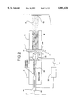
- the basic capillary discharge device with ablative liner is illustrated in FIG. 18. It consists of a long, narrow discharge channel comprised of an insulating wall with electrodes at either end. One end, usually the cathode, is closed off to contain the pressure generated by the discharge. The anode end is formed by an annular electrode, with an inner diameter that may sometimes be smaller than the capillary (forming a throat), through which the discharge plasma flows.
- the capillary electrodes are fabricated of typical high performance electrode materials such as tungsten, thoriated tungsten, graphite, copper alloys, or other advanced electrode materials designed for low erosion. Careful operational tailoring and optimization will be required to maximize electrode lifetimes.
- the single-shot capillary discharge chamber typically uses an ablative plastic liner to provide the working fluid (through ablation of the wall material), but repetitive systems can be (and have been) designed which utilize non-ablative ceramic walls and injection of a working fluid.
- the capillary is then driven with a short electrical pulse, anywhere from 10's of ⁇ sec to 2-3 msec in length, usually from a capacitive Pulse Forming Network (PFN).
- PFN capacitive Pulse Forming Network
- the length and diameter of the capillary are chosen so as to create the desired temperature of the gas in the capillary (for the given pressure), which is heated and ionized by the discharge, forming a plasma. This temperature, combined with the capillary geometry, creates an electrical resistance, which is matched to the impedance of the PFN.
- the discharge resistance is designed to be high--0.1 to 1.0 ohms. Since the parasitic resistance of the transmission circuit and the PFN is typically small, a few milliohms, most of the PFN energy is transferred to the discharge. Transfer efficiencies of >99% are not uncommon.
- Ceramics have essentially no tensile strength and so the ceramic tube is contained in a heat shrunk steel jacket which prestresses the ceramic so that it is always in compression even during the discharge.
- the working mass can also be introduced either as a liquid or as a gas, as opposed to relying on wall ablation.
- the capillary acts much like the combustion chamber of a pulsed rocket.
- the time for the heated gas to flow out of the capillary is controlled by the diameter of the anode throat, d*.
- d* the flow time in a vacuum is given by 2 L/c s , where L is the capillary length and c s is the sound speed.
- the time is 100 ⁇ sec.
- the flow time can be up to ten times longer.
- Capillary discharges operate at high pressures, and this feature can be used to great advantage in a thermal spray scheme, since the capillary discharge approach to thermal spray provides a means of achieving high pressure and high temperature, while at the same time achieving high mass density, something impossible to achieve in conventional plasma spray or combustion spray processes (including the D-Gun®).
- Pulsed plasma discharges can produce pressures and temperatures limited only by the material strength of the containment vessel. For instance, capillary discharge pressures up to nearly 690 MPa (100,000 psi) are routinely generated in electrothermal accelerators. Pulsed plasma discharges can produce gas flow velocities well above those produced by existing thermal spray devices, easily exceeding 20 km/s in vacuum for conditions of interest to thermal spray applications.
- Thermal spray devices based on repetitively operated pulsed plasma discharges can produce particle impact velocities of several km/s, as opposed to the maximum of 1.2 km/s typically achieved by existing detonation guns and High Velocity Oxy-Fuel (HVOF) sprays for only the smallest particles (10 ⁇ m).
- HVOF High Velocity Oxy-Fuel
- wire arc spray One of the most widely used thermal spray technologies is wire arc spray.
- One principal disadvantage of the wire-arc spray technique is the low particle velocity obtained, generally limited to about 250 mn/s. If the particle velocities obtained from wire-arc spray could be significantly increased without detracting from its other advantages, then generally superior quality coatings could be obtained. This would be of real interest for anti-corrosion coatings which need dense, hard, void-free coatings.
- the velocity limit is simply a result of the method used to atomize and accelerate the molten droplets, typically using just compressed air.
- Pulsed Wire Arc Spraying uses the technology of pulsed plasma jets to substantially increase the particle velocity of wire-arc spray devices, while maintaining the high deposition rates of conventional wire arc spray.
- the usual compressed air supply is replaced with a pulsed plasma jet.
- the capillary is oriented such that the jet aims directly through the arc between the wire electrodes, just as for compressed air.
- the high velocity jet accelerates the molten particles to much higher velocity than compressed air.
- the high gas density and gas velocity in the plasma jet i.e. the higher ⁇ gas v gas 2
- the wire arc can be formed in a conventional manner and energized by a typical arc welder-like power supply.
- the plasma jet begins pulsing immediately after arc initiation with the minimum time between pulses determined by the rate at which the arc re-establishes itself.
- To re-establish the arc in the afterglow of the jet uses a relatively low voltage arc welder power supply.
- the dc power supply for the wire arc is replaced by a smaller version of the pulse forming network powering the plasma jet.
- the wire arc operates in a pulsed manner, with a precisely tailored energy and pulse width delivered to the wire arc electrodes in each pulse.
- the wire-arc discharge and the plasma jet discharge occur essentially simultaneously.
- Table 1 shows examples of existing application areas for thermal spray coatings.
- Table 2 lists the major functions of thermal spray coatings.
- Table 3 compares existing thermal spray processes.
- Table 4 shows conventional wire-arc spraying characteristics.
- Table 5 lists typical applications and materials for wire-arc spraying.
- Table 6 details specific advantages of using pulsed wire-arc operation in conjunction with a pulsed plasma jet, over dc wire arc operation in conjunction with a pulsed plasma jet.
- Table 7 summarizes approximate PWAS operating parameters for one particular example.
- Table 8 shows technical advantages and drawbacks of PWAS.
- FIG. 1A is a schematic of one embodiment of the PWAS in which a small capillary discharge is used to trigger the main capillary discharge.
- FIG. 1B is a schematic of a preferred embodiment of the PWAS in which an externally impressed high voltage corona-like discharge provides a breakdown mechanism for initiating the main capillary discharge.
- FIG. 2 is a schematic representation of a simplified embodiment of the PWAS.
- FIGS. 3A, 3B and 3C show an early embodiment of the invention which utilized an ablative capillary liner.
- FIGS. 4A, 4B, 4C and 4D are details of four nozzle designs for the capillary.
- FIGS. 5A, 5B, 5C and 5D are cross-sections of the four-step process of the PWAS system.
- FIG. 6 is a photomicrograph showing the bonding interface between the substrate and a single PWAS splat.
- FIG. 7 shows a baseline coaxial pulsed wire arc configuration.
- FIG. 8 shows a dual-jet pulsed wire arc configuration.
- FIG. 9 illustrates the time scales for representative heat flux parameters for BN and SiC insulators.
- FIGS. 10A and 10B are plots of simulated droplet velocity versus time for aluminum and steel.
- FIGS. 11A and 11B are plots of simulated droplet velocity versus position for aluminum and steel.
- FIG. 16 is a plot of simulated velocity of 50 ⁇ m droplets of steel versus capillary discharge energy for different argon prefill pressures.
- FIG. 17 is a plot of simulated velocity of 50 ⁇ m droplets of aluminum versus capillary discharge energy for different argon prefill pressures.
- FIG. 18 is a schematic of a basic capillary discharge using wall ablation to provide working fluid mass to produce a plasma jet.
- Pulsed wire arc spraying uses the technology of pulsed plasma jets to substantially increase the particle velocity of wire-arc spray devices, while maintaining the high deposition rates of conventional wire arc spray.
- the invention is shown schematically in FIGS. 1A and 1B, with the main difference between the two versions being the method of initiating the main capillary discharge arc.
- the usual compressed air supply has been replaced with a pulsed plasma jet 1.
- the capillary 3 is oriented such that the jet aims directly through the arc 5 between the wires 7.
- the hot, high pressure plasma 9 exits through the open end of the capillary 11. Expansion of the plasma down the barrel/nozzle 13 cools the plasma and accelerates melted droplets stripped from the wires.
- a rapidly moving transient shock forms in the inert gas 15 which initially fills the barrel/nozzle 13, but quickly travels down the barrel/nozzle and exits as quasi-steady flow is established in the capillary/barrel 13.
- Flow velocities of >20 km/s are readily obtained in vacuum.
- the actual velocity is controlled by the specific geometry, the molecular weight and specific heat ratio of the gas, the background gas pressure, and the pulsed energy input.
- inert gas 15 is once again admitted flushing the system and preventing air from re-entering the barrel/nozzle 13 through the muzzle 16. The cycle then begins again.
- An inert gas shroud 15 can be incorporated into the muzzle to help protect particles from interacting with air prior to impacting and coating on the substrate 17.
- Liquid injection from supply 21 provides a way of introducing the working fluid into the inlet end 23 of the capillary 3 in a form that does not require mechanical confinement and thus is more suitable for repetitive operation at high deposition rates.
- a mist of liquid droplets 23 is injected into the capillary 3 immediately before the discharge is initiated.
- the arc discharge 25 then completely vaporizes the small droplets 23 and provides the same mass of gas in plasma 9 that would be equivalent to tens of atmospheres of confined gas prefill pressure.
- This method shown schematically in FIGS. 1A, 1B and 2, easily places the required few hundred mg or so of working fluid mass 23 into the capillary 3.
- the liquid is injected as a stream which is subsequently vaporized by the arc disharge.
- Liquid injection has the additional advantage that working fluid mass can be introduced into the capillary quasi-continuously, even during the discharge, as long as the pressure in the feed line 27 is higher than the capillary discharge pressure. This allows for extending of the discharge duration without capillary burnout due to mass starvation. For the present pulsed wire-arc spray device 31, continuous injection is not necessary. Pulsed injection can supply sufficient working fluid to achieve the performance desired.
- Cryogenic liquid argon is stored in dewars 21 and is pressure fed into the capillary using compressed helium.
- Liquid argon is expected to be injected into the capillary through an orifice 106 with either an actively driven fast valve or an automatic pressure driven check valve 107.
- the valve 107 opens to allow liquid argon to enter the capillary 3.
- the capillary pressure rises and closes the check valve automatically.
- the orifice 106 is sized to admit either a thin stream or a spray of liquid droplets into the capillary 3 with the desired mass flow rate for the given pressure differential. It may be desirable to atomize the liquid with the orifice 106 or to simply direct one spray stream along the axis or multiple spray streams directed at the capillary walls 108. Liquid injection in general, and cryogenic feed, in particular, has the attractive feature of providing additional cooling directly inside the capillary 3.
- a cooling water system 33 surrounds the capillary for cooling the capillary.
- the arc 25 is established between electrodes 35 and 37 using a high voltage power supply 39, which is charged by a plasma jet charging power supply 41.
- the capacitor bank 39 which provides energy to drive the main capillary discharge arc 25 current of up to a few tens of kiloamps, will operate at voltages no higher than 20 kV, and preferrably no more than 10 kV, in order to reduce cost and increase lifetime of the capacitors.
- Establishing the main discharge arc 25 cannot be accomplished by such a low voltage for capillary lengths greater than a few centimeters. Therefore, a method must be provided to initiate a sufficiently conducting path in the gas such that the voltage across the electrodes 35 and 37 will cause current to flow. Once conduction begins, the low impedance of the capillary power supply 39 will ensure that a rapidly rising current will ensue, heating and ionizing the gas and turning it into a plasma. The initiation method only needs to provide an extremely short duration "spark" breakdown path in order for the main capillary bank 39 to establish the capillary discharge.
- an initial conducting path is provided by the small hot plasma jet emanating from the trigger capillary 109.
- Trigger capillary 109 is roughly one tenth the volume and length of the main capillary 3, with an energy input only about one tenth that of the main capillary 3.
- the pressure and temperature reach values comparable to the main discharge.
- the tiny hot plasma jet proceeds into and through the gas in the main capillary, propagating down the axis and expanding radially until the front reaches near to electrode 35 at which time the voltage impressed between electrodes 35 and 37 by capacitor bank 39 is now sufficient to cause high voltage breakdown and current conduction through the hot conducting path left by the trigger plasma jet.
- Electrode 37 is shared by both the main capillary and the small trigger capillary.
- a trigger power supply 43 connected to the charging power supply 41 supplies power to a trigger electrode 45.
- a control system 47 connected by a fiber optic link 49 to a computer 51 controls the wire arc charging power supply 53 which charges the wire arc power supply 55.
- the control 47 also controls the plasma jet charging power supply 41.
- the power supply 39 is operated without a switch, since the gas in the capillary 3 acts as a virtual switch, which is "closed" by the small plasma trigger jet.
- a trigger switch 57 shown in power supply 43 is controlled by the control system 47.
- control system 47 controls similar trigger switches in power supply 55 to supply voltage and current to the wire arc 5 substantially concurrently.
- an adjustable time delay of up to a few microseconds between the firing of the capillary discharge and the firing of the wire arc.
- the small trigger plasma jet is replaced by an inductively coupled, high voltage spike produced in a high voltage pulse generator 110.
- Trigger pulse generator 110 produces a high voltage spike between electrodes 45 and 35 by inductive coupling through inductor 111.
- This voltage spike can be many tens of kV but which lasts for only nanoseconds. It produces a corona-like discharge along the inner wall of capillary 3 between electrodes 45 and 35.
- This annular conducting region provides a convenient breakdown path for the main capacitor bank 39 to establish the arc discharge 25. This method of arc initiation is preferred over the small triggering plasma jet since it reduces system complexity signficantly and provides a more desirable initial conductivity profile.
- the inert gas or liquid supply 27 provides fluid to an elongated inlet tube 59, which also serves as the inlet anode 37.
- the capillary arc power supply 39 is controlled by a switch 61 connected to the controller 47 shown in FIG. 1 to ignite the arc 25 in the capillary 3.
- a similar switch supplies power to the wires 7, igniting the wire arc 5.
- the wires are fed through insulating bushings 63 in the nozzle 13.
- the capillary electrode 35 is shown with a divergent opening 65, which feeds to the barrel 13.
- the tips 67 of the wire 7 are preferably almost flush with the inner surface 69 of the barrel, and are positioned close to the capillary exit 71.
- the nozzle 13 is diverging.
- FIGS. 3A-3C show an early embodiment 71 of the invention.
- the substrate 17 is mounted on a substrate holder 73 within a chamber 75 closed at both ends 77 and 79.
- Capillary tube 3 with a liner 81 extends into end 79 of the chamber 75, and a barrel 13 extends outward from the capillary tube and directs the plasma 9 to gap 5 between the wires 7.
- FIGS. 4A-4D show four nozzle choices for the capillary.
- FIG. 4A shows an expansion nozzle 83.
- FIG. 4B shows a converging nozzle 85 connected to the capillary 3.
- FIG. 4C show a converging/diverging nozzle 87 connected to the capillary 3.
- FIG. 4D shows a constant diameter nozzle 89 connected to the capillary.
- FIGS. 5A-5D show the four-step process in an early embodiment of the invention.
- the capillary 3 has the cathode 37 and the anode 35, and is connected to a barrel 13.
- Wires 7 provide a cathode and an anode opposite the substrate 17.
- FIG. 5A shows the initial state with both systems at rest, prior to firing.
- Each electrode pair is separately coupled electrically to a separate capacitor bank, (not shown here), to provide the pulsed energy source.
- Arcs 25 and 5 are ignited.
- Arc 5 melts the surface of the wires 7 at the arc, and arc 25 creates the plasma 9 within the capillary 3.
- the high speed, high temperature plasma 9 exits the capillary.
- the plasma 9 is shown stripping the melted particles from the wires 7 for atomizing and accelerating the particles 91 toward the substrate 17 to form a dense coating on the substrate.
- FIG. 6 shows a photomicrograph of the bonding interface 93 between the substrate 17 and a single splat 95 of the coating 19.
- FIG. 7 is a schematic representation of the base line coaxial pulsed wire arc spray configuration, with the nozzle 13 diverging at about 5°-30° and the wires 7 extending into the nozzle near the exit of the capillary tube.
- the ceramic capillary structure 3 is fabricated of BN, Si 3 N 4 , SiC, or other advanced ceramic to allow non-ablative operation.
- the working fluid is supplied through line 27 to the inlet 22, and an arc is ignited between the electrodes 35 and 37 to create the high speed, high temperature plasma 9, which strips melted particles from the surfaces of the wires 7 which are heated by an arc between ends of the wires. The melted particles 91 are accelerated toward the substrate 17.
- the working fluid is provided by injection of liquid argon, which provides the mass required to fill the capillary chamber 3 with a gas equivalent of 30 atmospheres, but without the need of mechanical confinement.
- Argon is currently supplied to many spray facilities in liquid form, since it is actually cheaper in bulk than the equivalent quantity of gas, and is easier to deal with.
- Use of atmospheric pressure gases for the working fluid appears to be useful only for very low spray rates, perhaps for fine detail work.
- the liquid argon is admitted through a triggered fast acting valve or an automatic check valve 107.
- the liquid enters through a small orifice at inlet 22, is partially vaporized on contact with the walls, and quickly fills the capillary 3 with gas 23 and a mist of liquid droplets.
- the electrodes 35 and 45 generate a spark which induces breakdown through the gas 29 of the entire capillary channel.
- the discharge quickly raises the capillary pressure to about 1 kbar ( ⁇ 15,000 psi) and to a temperature of roughly 1 eV (11,600 K).
- the wire arc electrodes 7 penetrate through the barrel/nozzle assembly 13 through insulating bushings 63 and are roughly flush with the inner wall 112 which is preferrably a refractory metal or ceramic liner. The location of the electrodes is close to the capillary anode 35.
- the nozzle 13 has a slight taper of about 5-10 degrees.
- Bushings 63 also provide pressure sealing around the wires.
- the wire arc discharge occurs simultaneously or a few microseconds after the plasma jet is initiated to provide sufficient time for conductive plasma to exit the capillary and provide an easy breakdown path for the wire discharge.
- the discharge pulse lasts about 100 ⁇ s for both capillary discharge and wire arc discharge.
- Table 7 summarizes approximate operating parameters of the Pulsed Wire Arc Spray device for the capillary size listed.
- FIG. 8 shows one embodiment of a dual jet configuration for spraying small inner bores such as pipes and tubes, one of the more difficult tasks for thermal spray devices of any kind.
- An interesting application is spraying iron on the inner surface of next generation aluminum engine block cylinders 101. Space is constrained. Existing spray devices have to spray at an angle or use performance-robbing right angle diverting attachments.
- the Pulsed Wire Arc Spray device is ideally suited for this application by using the conceptual configuration shown in FIG. 8.
- Working fluid for this application does not need to be liquid argon. It can be room temperature liquid hydrocarbons, which in this case are considerably more convenient and cost effective, since the presence of the carbon is not necessarily a negative feature.
- the device 97 operates in the same general manner as the previously described baseline configuration, but is more compact and designed to move through a tubular enclosure.
- the power supplies 39 are located externally with coaxial cables 105 delivering the pulsed power to the capillaries 3.
- the two jets 35 are connected in series and fire simultaneously towards each other, causing the jets to stagnate at the center and redirect the high pressure, high velocity flow out through the side port with a small nozzle 13.
- the jets can be powered by separate capacitor banks or arranged.
- the wire-arc electrodes 7 are continuously fed toward each other in this side port.
- PWAS Planar-to-Value spray rate
- the dual jet configuration is generally indicated by the numeral 97. Parts of the dual jet which are similar to the single jet are numbered with the same numbers as the single jet.
- the central monoblock ring 99 acts as the electrode 35 for both capillary discharges. Two separate electrodes could also serve this function, but increases complexity and part count and is less attractive.
- the electrodes 37 are provided at the inlet ends 22 of the capillary tubes 3. Separate capillary power supplies 39 controlled by separate switches 61 may be employed. Another embodiment would use a single capillary power supply and operate the two jets electrically in series.
- the consumable wire arc electrodes 7 are fed into the short divergent nozzle 13 at the exit 11.
- only a single wire electrode is used in conjunction with a non-consumable electrode, for which the central monobloc 99 is the preferred choice.
- the jet gases propel the melted droplets 91 onto the inner cylinder surfaces 101 of the engine block 103 at high speed.
- a mechanical means is used to move the plasma jet apparatus 97 with respect to the engine block 103, or to move the engine block 103 with respect to the plasma jet 97, to provide a uniform coating. It is preferred that all attachments to the sprayer unit enter the tubular enclosure to be sprayed from one side only so that dis-connections and re-connections of cables, leads, and feed lines do not have to be made prior to repositioning for spraying another tubular enclosure.
- Heating of a liquid spray by an electrical discharge is governed by heat transport to the droplet phase. Once evaporated, the vapor is heated by the discharge plasma to a temperature and pressure determined by the discharge power, chamber geometry, and mass flow rate. Proper distribution of the spray in the chamber is important to prevent local burnout.
- the main possibilities involve spraying water, liquid hydrocarbons, liquid argon and liquid nitrogen.
- Water injection is attractive for spraying materials such as oxides where surface interaction with oxygen is less of a concern.
- injection of fluid as a stream is acceptable, it is preferable to inject fluid as a mist.
- Liquid can also be directed onto the surface of the capillary liner. Absorption of vaporization energy helps cool down the walls.
- Liquid hydrocarbons are useful for spraying some materials such as iron or steel, but introduces safety issues associated with combustible fuel. Injection is similar to fuel injection in a car engine.
- Liquid nitrogen can also be considered inert in some applications.
- Liquid argon is readily available in many thermal spray shops, since it is often supplied in liquid form to provide the gas used in plasma sprayers.
- Argon is actually cheaper supplied in bulk liquid form than in gaseous form, which provides a cost advantage.
- Breakup is a result of more than one mechanism, but in general it is a process in which the stabilizing influence of surface tension is disrupted by an external force, namely high velocity gas flow. Breakup is caused primarily by instabilities caused by a light fluid pushing against a heavier fluid, and partly by viscous forces which tend to distort the outer periphery of the molten droplet.
- the kinetics of all atomization processes typically involve one or more of the following five steps:
- the extension of the bulk liquid (e.g. molten metal) into sheets, jets, films, or streams is caused by accelerating the liquid in some prescribed manner.
- Droplet breakup and atomization is essentially a competition between external dynamic pressure and viscous shear forces which tend to tear the drop apart, and the surface tension and internal viscous forces which tend to resist deformation and breakup.
- the total amount of energy required increases rapidly as the mean particle size decreases (i.e. as the total surface area increases). Breakup and atomization of liquid droplets is ultimately governed by how efficiently energy from the atomizing fluid can be coupled into the molten metal generating fine isolated particles.
- a drop of liquid moving in a gaseous medium experiences secondary disintegration when the dynamic pressure due to gas stream velocity exceeds the restoring force due to surface tension. This occurs if the Weber number, defined as
- ⁇ g is the gas density
- u r is the relative velocity between gas and drop
- D p is the drop diameter
- ⁇ p is the surface tension of the liquid drop.
- the critical value is about 13 for liquids of low viscosity when the relative velocity is applied very suddenly, as would be the case for an impinging shock front. This is termed stripping breakup. If the relative velocity is applied slowly, then the value is about 22. This would be the case, for instance, for a drop accelerating under gravity. Intuitively, one would expect the critical value to increase with the viscosity of the liquid, and this is indeed the case.
- the critical value will increase by the factor k.sub. ⁇ p defined by
- ⁇ p is the liquid viscosity. This makes sense physically, since a higher liquid viscosity tends to make droplet breakup more difficult.
- particle size depends primarily on gas density ⁇ , the relative velocity u r , and the surface tension ⁇ m .
- gas density ⁇ the relative velocity u r
- surface tension ⁇ m the surface tension
- Atomization of the molten wire material by the plasma jet has the distinct advantage of operating at higher gas density and gas flow velocity than conventional wire arc spray, the two most important controllable factors in how small a droplet forms.
- Flow velocities can be increased by at least an order of magnitude relative to conventional wire arc spray techniques while simultaneously increasing gas densities an order of magnitude.
- Pulsed plasma jet technology therefore provides an innovative solution to increasing both gas density and velocity, leading to finer spray atomization and consequently higher velocity droplets.
- Acceleration of a single coating droplet is determined by solving the drag equation ##EQU1## where u p , ⁇ p , and d are the particle velocity, density and diameter respectively, ⁇ g and u g . are the gas density and velocity as determined by the fluid equations, and C d is the drag coefficient, which is approximately 0.44 for most cases of interest here.
- This equation tells us that for a given particle size and density, the determining factors are the velocity of the gas relative to the particle and the density of that gas. The higher the gas density and the higher the relative velocity, the stronger is the accelerating force on the particle. In essence, one of the goals of all thermal spray devices is to maximize this quantity.
- a good coating also requires the proper thermal and chemical state of the droplet, typically either molten or in a plastic state just below the melting point (at least for powders).
- One problem with conventional wire-arc spray is the use of cold gas to accelerate the droplets resulting in in-flight freezing of many droplets prior to impact on the target substrate. Using a pulsed plasma jet eliminates this problem.
- a working fluid introduced into the capillary region in a repetitive manner allows a ceramic capillary liner to survive essentially indefinitely, and yet still provides sufficient mass to accelerate the particles without exceeding chamber and barrel temperature limits. It is desirable to operate the capillary discharge at roughly 1 kbar and 1 eV to achieve the desired performance, where 1 eV is defined as 11,600 K.
- the pulsed process has several specific advantages over conventional wire arc spray atomization which makes it very attractive from a commercial point of view.
- the first of these is that the pulsed plasma jet provides an initial strong shock which induces primary disintegration of the droplets in a manner which is potentially more efficient than allowed by continuous flow techniques. This is partly a result of the fast, high pressure shock front (.sup. ⁇ 1 kbar) which impacts the droplets and partly due to the fact that the melt can be arranged so that it and the plasma jet have comparable cross-sectional dimensions in the atomization interaction zone. These small droplets form in just a few mm. These plasma jets are efficient atomizers.
- Another advantage is that after the initial breakup of the melt, further secondary disintegration is induced by the high speed gas flow behind the shock.
- gas flow velocities as high as 20-30 km/s are readily attained in vacuum, the process operates with gas velocities in the 3-5 km/s range.
- Conventional wire arc spray is limited to a few hundred meters per second due to the use of cold air.
- the plasma jets high velocity can be obtained without a corresponding decrease in gas density (relative to cold air flow) and thus can provide a momentum flux two orders of magnitude higher than is possible with cold gases.
- the high temperature of the gas (which can be greater than the melt temperature) prevents premature solidification of the droplets prior to complete disintegration. This feature, along with the higher gas flow velocity, prevents the formation of solid inclusions in the coating.
- Case A the expansion nozzle case
- Case D gives better performance, since the density of gas is used most effectively.
- a concern is that a non-diverging barrel/nozzle would lead to droplets sticking to the wall, and degrade performance.
- the thermal loads to the wall are considered to determine at what temperatures the capillary discharge can operate and for how long.
- This equation indicates that ablation can be avoided, for a given heat flux q, by keeping the pulse time sufficiently short.
- the so-called “grace period” is the time a surface can be exposed to a given thermal flux before ablation begins, and is different for each material as determined by its a and vaporization temperature.
- FIG. 9 illustrates the time scales for representative heat flux parameters for a BN insulator.
- the curve labeled 3-BN represents the case for a flat radial temperature profile in the capillary.
- Curve 2, SiC or BN represents the more realistic case in which a lower temperature boundary layer forms at the wall which can reduce the heat flux q to the wall by as much as a factor of two over the heat flux calculated from the core plasma temperature on axis.
- Curve 1, SiC is for SiC with a reduced wall flux.
- the capillary discharge operates at temperatures in the 1.0 to 1.5 eV range for 100-1000 microseconds without damage to the ceramic insulator.
- the peak temperature should be limited to about 1.0 eV.
- the capillary should not be exposed to this temperature for more than 200-300 ⁇ s. Operating at a relatively high temperature maximizes the sound speed which ultimately determines the droplet speed.
- Knowing the temperature limit range allows operating in the 1 kbar range.
- Working backwards yields the density required to obtain 1 kbar pressures at 1 eV.
- For the Ar mix this turns out to correspond to a prefill pressure of 30 atm.
- a prefill of 10 atm allows peak pressures of about 0.33 kbar, which is still substantially above existing thermal spray devices.
- the case of a capillary 1 cm in diameter and 10 cm long, with a nozzle expanding out to 2 cm diameter over a distance of 20 cm corresponds to case A in FIG. 4A with a straight barrel section of zero length.
- the capillary is pre-filled to 30 atm with Argon gas, and the capillary discharge is simulated by uniformly depositing a total of 1 kJ of energy into the capillary volume over a time of 100 ⁇ s.
- the capillary contains a total of 308 mg of Argon, allowing an efficient acceleration of 30-60 mg of molten droplets per pulse.
- the wire arc electrodes are located at 12 cm.
- the total gas flow rate for these conditions at 10 Hz firing rate is about 300 SCFH, yielding a spray rate of about 1 kg/hr.
- the spray rate goes up to about 10 kg/hr, and the gas flow rate is about 3000 SCFH, comparable to wire are spray numbers, but at much higher impact velocities.
- the resulting velocity time histories for 10, 50 and 100 ⁇ m droplets of aluminum and steel are shown in FIGS. 10 and 11, as functions of time and position respectively.
- the 10 ⁇ particles will continue accelerating outside the barrel.
- the 10 ⁇ particles tend to come up to speed fairly quickly and then basically "coast" with the flow the rest of the way, since the relative velocity has become rather small and consequently also the accelerating drag.
- the larger particles continue to accelerate inside the barrel/nozzle, and attain roughly another 200 m/s in velocity.
- the barrel allows the larger particles to continue accelerating. With some optimization, relatively narrow velocity distributions are achieved.
- the velocities of these larger particles are greater than the velocities currently attained by only 10 ⁇ particles in existing thermal spray devices. From an energetics point of view, the kinetic energy of 30 mg of any material at 1000 m/s is only 15 J, only 1.5% of the total ohmic heating energy in the capillary discharge.
- Results from a series of simulation runs are compiled in the plot in FIGS. 16 and 17, which show the velocities achieved by 50 ⁇ m sized droplets of aluminum and steel versus the capillary discharge energy for three different argon prefill pressures (10, 30, and 50 atm).
- the peak temperature attained in the capillary shows the approximate operational limits at 1 eV.
- a prefill of 30 atm is a comfortable range in which to work.
- the droplets should originate right at the exit immediately downstream of the second capillary electrode.
- Pulsed Wire Arc Sprayer is readily scalable to larger and smaller (for fine work) deposition rates by adjusting the size of the capillary.
- the energy per pulse is typically adjusted to maintain roughly 1 kbar, 1 eV peak plasma conditions in the capillary.
- the amount of material that can be sprayed per pulse is roughly proportional to the gas mass in the capillary.
- the energy per pulse also scales as the gas mass for constant peak temperature. This drives the system to higher pressure if the capillary volume remains constant.
- the capillary operates at pressures 2-4 times larger if SiC is used instead of BN for the capillary liner, for spraying 60-90 mg per pulse (instead of the baseline 30 mg).
- the material sprayed per pulse doubles, i.e. 120-180 mg per pulse. This corresponds to about 4-6 kg/hr at a 10 Hz firing rate. Increasing the firing rate increases the spray rate proportionally. Although higher pulse rates are possible, a practical upper bound on the firing rate appears to be in the 50-100 Hz range.
Landscapes
- Engineering & Computer Science (AREA)
- Chemical & Material Sciences (AREA)
- Physics & Mathematics (AREA)
- Plasma & Fusion (AREA)
- Chemical Kinetics & Catalysis (AREA)
- Materials Engineering (AREA)
- Mechanical Engineering (AREA)
- Metallurgy (AREA)
- Organic Chemistry (AREA)
- Electromagnetism (AREA)
- Nozzles (AREA)
- Coating By Spraying Or Casting (AREA)
Abstract
Description
N.sub.Weg =ρ.sub.g u.sub.r.sup.2 D.sub.p /σ.sub.p,
k.sub.μp =1+[μ.sub.p /(D.sub.p ρ.sub.p σ.sub.p).sup.1/2 ],
                                  TABLE 1
__________________________________________________________________________
Application Area
               Some Specific Current Applications
__________________________________________________________________________
Automotive     Pistons, valves, piston fire decks, cylinder heads,
               cylinder bores, fuel
   injectors, valve train components, crankshaft, turbochargers
  Aerospace Engine seals, rocket & jet engine nozzles, coatings on
               lightweight
   components, structural engine parts, control surfaces
  Electronics Magnetic materials, dielectrics, ceramic substrates
                Pulp & Paper Industry Recovery boilers, rolls, Yankee
               dryers, digester welds
  Printing Industry Engraver rolls, plate and blanket cylinders, draw
               rolls, analox rolls,
   transmission components
  Near-Net Shape Spray Forming Mold fabrication without machining
                Superconductors Magnetic shields, microwave components
                Infrastructure Protection Bridges and other steel and
               concrete structures
  Mining & Petrochemical Industry Pump, bearing and seal protection;
               drilling tools & drill-string
   components, valves
  Biomedical Implants Hydroxyapatite coatings, dental implants, hip
               replacement
  Chemical Industry Pumps, bearings and seals repair; corrosion control
               in pipes, pumps,
   vats and reactors
  Power Generation Corrosion & erosion in plants that burn high-sulfur
               coal
__________________________________________________________________________
              TABLE 2
______________________________________
Major Functions of
  Thermal Spray Coatings
______________________________________
Wear Resistance
  Thermal Insulation
  Corrosion Resistance
  Chemical Resistance
  Abradable & Abrasive Coatings
  Electrical Insulation or Conductance
  Medically Compatible Coatings
  Dimensional Restoration
  Polymer
  RFI/EMI Shielding
  Cosmetic Repair
______________________________________
                                  TABLE 3
__________________________________________________________________________
Comparison of thermal spray technologies.
__________________________________________________________________________
Flame powder: Powder feedstock, aspirated into the oxygen/fuel-gas flame,
is melted and carried by the flame onto the
 workpiece. Particle velocity is relatively low, and bond strength of
deposits is low. Porosity is high and cohesive strength
  is low. Spray rates are usually in the 0.5 to 9 kg/h (1 to 20 lb/h)
range. Surface temperatures can run quite high.
  Flame wire: In flame wire spraying, the only function of the flame is
to melt the material. A stream of air then
  disintegrates the molten material and propels it onto the workpiece.
Spray rates for materials such as stainless steel are
  in the range of 0.5 to 9 kg/h (1 to 20 lb/h). Substrate temperatures
are from 95 to 205° C. (200 to 400° F.) because of the
 excess energy input required for flame melting.
 Wire arc: Two consumable wire electrodes are fed into the gun, where
they meet and form an arc in an atomizing air
  stream. The air flowing across the arc/wire zone strips off the molten
metal, forming a high-velocity spray stream. The
  process is energy efficient: all input energy is used to melt the
metal. Spray rate is about 2.3 kg/h/kW (5 lb/h/kW).
  Substrate temperature can be low because energy input per pound of
metal is only about one-eighth that of other spray
  methods.
  Conventional plasma: Conventional plasma spraying provides free-plasma
temperatures in the powder heating region
  of 5500° C. (10,000° F.) with argon plasma, and 4400.degre
e. C. (8000° F.) with nitrogen plasma - above the melting point of
any
 known material. To generate the plasma, an inert gas is superheated by
passing it through a dc arc. Powder feedstock is
  introduced and is carried to the workpiece by the plasma stream.
Provisions for cooling or regulation of the spray rate may
  be required to maintain substrate temperatures in the 95 to 205°
C. (200 to 400° F.) range. Typical spray rate is 0.1 kg/h/kW
 (0.2 lb/h/kW).
 Detonation gun: Suspended powder is fed into a 1 m (3 ft) long tube
along with oxygen and fuel gas. A spark ignites
  the mixture and produces a controlled explosion. The high temperatures
and pressures (1 MPa, 150 psi) that are generated
  blast the particles out of the end of the tube toward the substrate.
 High-Velocity OxyFuel: In HVOF spraying, a fuel gas and oxygen are used
to create a combustion flame at 2500 to
  3100° C. (4500 to 5600° F.). The combustion takes place
at very high chamber pressure (150 psi), exiting through a small-
 diameter barrel to produce a supersonic gas stream and very high
particle velocities. The process results in extremely
  dense, well-bonded coatings, making it attractive for many corrosion-res
istant applications. Either powder or wire
 feedstock can be sprayed, at typical rates of 2.3 to 14 kg/h (5 to 30
lb/h).
  High-energy plasma: The high-energy plasma process provides significantl
y higher gas enthalpies and temperatures
 especially in the powder heating region, due to a more stable, longer
arc and higher power density in the anode nozzle.
  The added power (two to three times that of conventional plasma) and
gas flow (twice as high) provide larger, higher
  temperature powder injection region and reduced air entrainment. All
this leads to improved powder melting, few unmelts,
  and high particle impact velocity.
  Vacuum plasma: Vacuum plasma uses a conventional plasma torch in a
chamber at pressures in the range of 10 to 15
  kPa (0.1 to 0.5 atm). At low pressures the plasma is larger in diameter,
 longer, and has a higher velocity. The absence
 of oxygen and the ability to operate with higher substrate temperatures
produces denser, more adherent coatings having
  much lower oxide contents.
__________________________________________________________________________
              TABLE 4
______________________________________
Conventional Wire Arc Spraying Parameters
______________________________________
Arc Temperature   up to 5000 C.
  Particle Velocity 100-300 m/s
  Spray Distance 10-25 cm
  Power Input 6-80 kW
  Air Flow Rate up to 2500 SCFH
  Coating Thickness 0.05-0.5 mm (or more)
  Consumables wires, diameter 1.6-3.2 mm
______________________________________
              TABLE 5
______________________________________
Typical applications and materials for wire arc spray.
    Field          Material   Application
______________________________________
1)  Machine elements:
                   Al, Zn     rolls, shafts
   antifretting and wear cored wires, crankshafts
   restoration steels, NiCr plungers,
   clearance control  axes, gear boxes
  2) Corrosion protection Al, Zn, AlMg bridges and other
   atmosphere  metallic structures
   sea  pipings, power
     boilers, offshore
     platforms
  3) Electric and electronic Al, Cu, Zn, resistors, capacitors,
   applications NiCr RF shielding on
     nonmetallic
     components, discrete
     conductive parts on
     plastic or ceramic
     substrates
  4) Other applications Zn, Pb, Al, casting molds; e.g.,
    NiAl, NiCr for shoe soles,
    steels, shielding of X-ray
    cored wires rooms, bond
     coatings, slab
     marking
______________________________________
              TABLE 6
______________________________________
Advantages of pulsed wire arc operation
  over dc arc operation.
______________________________________
1) Arc initiation does not require physical touching
  of the electrodes
  2) Mass melted per pulse is precisely metered to
  provide independent control and matching to a
  pulsed plasma jet
  3) The wire arc PFN can be designed for more
  efficient pulsed operation than can a dc arc-
  welder type supply
  4) Independent control of the relative timing of
  plasma jet and molten droplet generation
  5) More efficient utilization of the wire mass (less
  wall losses)
  6) More freedom to select pulse rate
______________________________________
              TABLE 7
______________________________________
Approximate Parameters for Baseline Size of Pulsed
  Wire Arc Sprayer
     System Parameter
                     Value
______________________________________
Barrel/Nozzle Length
                 10-20        cm
  Capillary ID 1.0 cm
  Capillary length 10 cm
  Gas density 0.049 gm/cm.sup.3
  Gas mass in capillary 308 mg
  Peak droplet velocity 1600-1800 m/s
  Spray rate 1-15 kg/hr
  Droplet mass per pulse 30-90 mg
  Pulse rate 10-50 pps
  Fill Pressure ˜30 atm
  Peak Pressure ˜1000 atm
  Peak temperature ˜1 eV
  Capillary Energy per pulse 1-2 kJ
  Average jet power 10-50 kW
  Capillary Current 10-30 kA
  Discharge Duration ˜100 μs
______________________________________
                                  TABLE 8
__________________________________________________________________________
Technical Advantages of Pulsed Wire Arc Spray
__________________________________________________________________________
Higher velocity impact (1000-2000 m/s, which is 3-6 times conventional
technology)
  Can achieve plasma spray or HVOF quality coatings using wire arc
technology
  Utilizes wire feed stock which is generally much cheaper than powder
feed stock for the same material
  Independent control of thermal and chemical environment, controllable
working gas
  Potential for true metillurgical bonding rather than just mechanical
gripping of the surface
  No combustible gases used making system much safer
  No vacuum system needed, high purity maintained by use of only inert
gases
  Working fluid can be tailored for specific powders independent of
energy input
  Potential elimination of grit blasting prior to spraying due to higher
velocity impact
  Can achieve more uniform spray pattern and particle velocity distributio
 Higher performance will allow use of cheaper coating materials
 Very high velocity allows high quality coatings at greater spray angles
of incidence
  Reduced substrate heating compared to plasma spray or HVOF, allowing
high performance spraying on
  composites and other low temperature substrates
  Advanced operating modes include functionally gradient coatings
 Hardware readily scaled to large or small sizes, power levels, and
deposition rates
  Can readily model gun performance, reducing testing times
  Reactive spraying at high pressures may increase reaction rate to more
interesting rates
  Advanced operating modes include functionally gradient coatings using
multiple wires of different composition
__________________________________________________________________________
Potential Drawbacks of Pulsed Wire Arc Spray
__________________________________________________________________________
High pressure, high temperature operation could potentially lead to
relatively short lifetimes for some
  components, such as ceramic liner, electrodes, and barrels
  Seals for wire feed system may be high maintenance
  High voltage operation - but not significantly different than high
power plasma spray
  Hand held units appear unlikely at the present time
__________________________________________________________________________
Claims (46)
Priority Applications (1)
| Application Number | Priority Date | Filing Date | Title |
|---|---|---|---|
| US08/900,468 US6001426A (en) | 1996-07-25 | 1997-07-25 | High velocity pulsed wire-arc spray |
Applications Claiming Priority (2)
| Application Number | Priority Date | Filing Date | Title |
|---|---|---|---|
| US2264296P | 1996-07-25 | 1996-07-25 | |
| US08/900,468 US6001426A (en) | 1996-07-25 | 1997-07-25 | High velocity pulsed wire-arc spray |
Publications (1)
| Publication Number | Publication Date |
|---|---|
| US6001426A true US6001426A (en) | 1999-12-14 |
Family
ID=26696167
Family Applications (1)
| Application Number | Title | Priority Date | Filing Date |
|---|---|---|---|
| US08/900,468 Expired - Lifetime US6001426A (en) | 1996-07-25 | 1997-07-25 | High velocity pulsed wire-arc spray |
Country Status (1)
| Country | Link |
|---|---|
| US (1) | US6001426A (en) |
Cited By (89)
| Publication number | Priority date | Publication date | Assignee | Title |
|---|---|---|---|---|
| WO2001032949A1 (en) * | 1999-10-30 | 2001-05-10 | Agrodyn Hochspannungstechnik Gmbh | Method and device for plasma coating surfaces |
| WO2001071053A1 (en) * | 2000-03-24 | 2001-09-27 | Werner Jung | Method for the production of a material coating on a surface |
| WO2002093996A1 (en) * | 2001-05-10 | 2002-11-21 | Parker Hannifin Corporation | Manufacture of electronics enclosure having a metallized shielding layer |
| US6592935B2 (en) | 2001-05-30 | 2003-07-15 | Ford Motor Company | Method of manufacturing electromagnetic devices using kinetic spray |
| US6592947B1 (en) | 2002-04-12 | 2003-07-15 | Ford Global Technologies, Llc | Method for selective control of corrosion using kinetic spraying |
| US6610959B2 (en) | 2001-04-26 | 2003-08-26 | Regents Of The University Of Minnesota | Single-wire arc spray apparatus and methods of using same |
| US6612480B1 (en) * | 2000-11-21 | 2003-09-02 | C.A. Patents, L.L.C. | Method of forming preforms for metal repairs |
| US20030208904A1 (en) * | 2002-05-07 | 2003-11-13 | Tefft Stephen Wayne | Method for providing a rotating structure having a wire-arc-sprayed aluminum bronze protective coating thereon |
| US20030219542A1 (en) * | 2002-05-25 | 2003-11-27 | Ewasyshyn Frank J. | Method of forming dense coatings by powder spraying |
| US6666646B1 (en) * | 1999-07-30 | 2003-12-23 | Chromalloy Holland B.V. | Drag reduction for gas turbine engine components |
| WO2003101621A3 (en) * | 2002-06-01 | 2004-03-04 | Surface Innovations Ltd | Application of a coating forming material onto at least one substrate |
| US20040066874A1 (en) * | 2002-07-31 | 2004-04-08 | Kim Young Jin | Method for forming coatings on structural components with corrosion-mitigating materials |
| US6730370B1 (en) | 2000-09-26 | 2004-05-04 | Sveinn Olafsson | Method and apparatus for processing materials by applying a controlled succession of thermal spikes or shockwaves through a growth medium |
| US20040202797A1 (en) * | 2001-05-30 | 2004-10-14 | Ford Global Technologies, Llc | Method of manufacturing electromagnetic devices using kinetic spray |
| FR2859065A1 (en) * | 2003-08-06 | 2005-02-25 | Saint Louis Inst | Plasma generator incorporating a smaller high voltage device for igniting a propulsive charge for the projectile of a tubular weapon |
| US20050175411A1 (en) * | 2004-02-06 | 2005-08-11 | Lichtblau George J. | Process and apparatus for highway marking |
| US20050181121A1 (en) * | 2004-02-06 | 2005-08-18 | Lichtblau George J. | Process and apparatus for highway marking |
| US20050199486A1 (en) * | 2004-03-12 | 2005-09-15 | Applied Materials, Inc. | Refurbishment of sputtering targets |
| US20050217238A1 (en) * | 2003-10-16 | 2005-10-06 | Land H B Iii | Pulsed plasma thruster and method of making |
| US6972115B1 (en) | 1999-09-03 | 2005-12-06 | American Inter-Metallics, Inc. | Apparatus and methods for the production of powders |
| US20060000351A1 (en) * | 2004-06-30 | 2006-01-05 | Schenkel Jerry L | Piston for an engine |
| US20060024440A1 (en) * | 2004-07-27 | 2006-02-02 | Applied Materials, Inc. | Reduced oxygen arc spray |
| US20060021870A1 (en) * | 2004-07-27 | 2006-02-02 | Applied Materials, Inc. | Profile detection and refurbishment of deposition targets |
| US20060062928A1 (en) * | 2004-09-23 | 2006-03-23 | Lichtblau George J | Flame spraying process and apparatus |
| US20060081459A1 (en) * | 2004-10-18 | 2006-04-20 | Applied Materials, Inc. | In-situ monitoring of target erosion |
| US20060088725A1 (en) * | 2004-10-26 | 2006-04-27 | Ruggiero Peter F | Corrosion-resistant coating for metal substrate |
| US7043069B1 (en) * | 1999-03-11 | 2006-05-09 | Linde Gas Aktiengesellschaft | Quality assurance during thermal spray coating by means of computer processing or encoding of digital images |
| EP1679388A1 (en) * | 2003-10-22 | 2006-07-12 | Yamada Corrosion Protection Co., Ltd. | Method of thermal spraying |
| US20060292392A1 (en) * | 2004-10-26 | 2006-12-28 | Froning Marc J | Corrosion-resistant coating for metal substrate |
| US20070056933A1 (en) * | 2005-09-13 | 2007-03-15 | Ford Global Technologies, Llc | Method for producing a variable flow of melted material and articles therefrom |
| US20070116516A1 (en) * | 2005-11-22 | 2007-05-24 | Lichtblau George J | Process and apparatus for highway marking |
| US20070116865A1 (en) * | 2005-11-22 | 2007-05-24 | Lichtblau George J | Process and apparatus for highway marking |
| US20070113781A1 (en) * | 2005-11-04 | 2007-05-24 | Lichtblau George J | Flame spraying process and apparatus |
| US20070154620A1 (en) * | 2006-01-05 | 2007-07-05 | Lawrynowicz Daniel E | Method for fabricating a medical implant component and such component |
| US20070156249A1 (en) * | 2006-01-05 | 2007-07-05 | Howmedica Osteonics Corp. | High velocity spray technique for medical implant components |
| US20070158446A1 (en) * | 2006-01-05 | 2007-07-12 | Howmedica Osteonics Corp. | Method for fabricating a medical implant component and such component |
| US20070261663A1 (en) * | 2006-05-10 | 2007-11-15 | Warran Lineton | Thermal oxidation protective surface for steel pistons |
| US20080253040A1 (en) * | 2007-04-16 | 2008-10-16 | Thangavelu Asokan | Ablative Plasma Gun |
| WO2009005568A1 (en) * | 2007-05-30 | 2009-01-08 | Georgia Tech Research Corporation | Methods and apparatus for surface ablation |
| US20090123659A1 (en) * | 2002-07-25 | 2009-05-14 | Creavis Gesellschaft Fuer Tech. Und Innovation Mbh | Method for producing a self-cleaning surface by flame spray coating |
| US20090134129A1 (en) * | 2007-11-27 | 2009-05-28 | General Electric Company | Ablative plasma gun apparatus and system |
| US20090166344A1 (en) * | 2005-09-08 | 2009-07-02 | Pauli Hamalainen | Method and Apparatus for Short-Arc Welding |
| US7632575B2 (en) * | 2003-12-03 | 2009-12-15 | IMDS, Inc. | Laser based metal deposition (LBMD) of implant structures |
| US20090318846A1 (en) * | 2004-05-28 | 2009-12-24 | Georgia Tech Research Corporation | Methods and apparatus for surface ablation |
| US7666522B2 (en) * | 2003-12-03 | 2010-02-23 | IMDS, Inc. | Laser based metal deposition (LBMD) of implant structures |
| EP2113578A3 (en) * | 2008-04-12 | 2010-02-24 | Jürgen Berthold | Metal body with metallic protective coating |
| US20100131062A1 (en) * | 2008-11-24 | 2010-05-27 | Promimic Ab | Methods and systems of controlled coating of nanoparticles onto micro-rough implant surfaces and associated implants |
| US7763325B1 (en) * | 2007-09-28 | 2010-07-27 | The United States Of America As Represented By The National Aeronautics And Space Administration | Method and apparatus for thermal spraying of metal coatings using pulsejet resonant pulsed combustion |
| US7901552B2 (en) | 2007-10-05 | 2011-03-08 | Applied Materials, Inc. | Sputtering target with grooves and intersecting channels |
| US20110089144A1 (en) * | 2008-07-03 | 2011-04-21 | Esab Ab | Device for handling powder for a welding apparatus |
| DE102007002161B4 (en) * | 2007-01-15 | 2011-11-10 | Sergei Afanassev | Electric rocket engine with powdered fuel |
| US20120018407A1 (en) * | 2009-03-31 | 2012-01-26 | Ford Global Technologies, Llc | Plasma transfer wire arc thermal spray system |
| US20120019143A1 (en) * | 2008-05-05 | 2012-01-26 | Astrium Gmbh | Plasma Generator and Method for Controlling a Plasma Generator |
| US20120135272A1 (en) * | 2004-09-03 | 2012-05-31 | Mo-How Herman Shen | Method for applying a low residual stress damping coating |
| US20120145680A1 (en) * | 2010-12-13 | 2012-06-14 | The Esab Group, Inc. | Method and plasma arc torch system for marking and cutting workpieces with the same set of consumables |
| US20120160813A1 (en) * | 2010-12-22 | 2012-06-28 | Kowalsky Keith A | Thermal Spray Method and Apparatus Using Plasma Transferred Wire Arc |
| US20120175355A1 (en) * | 2011-01-10 | 2012-07-12 | Lalam Sree Harsha | Method of welding nickel-aluminide |
| US20130059087A1 (en) * | 2011-09-02 | 2013-03-07 | Guardian Industries Corp. | Method of strengthening glass using plasma torches and/or arc jets, and articles made according to the same |
| US8647484B2 (en) | 2005-11-25 | 2014-02-11 | Applied Materials, Inc. | Target for sputtering chamber |
| US20140051254A1 (en) * | 2010-05-21 | 2014-02-20 | Lam Research Corporation | Movable chamber liner plasma confinement screen combination for plasma processing apparatuses |
| US20140131311A1 (en) * | 2012-11-13 | 2014-05-15 | Samsung Display Co., Ltd | Thin film forming apparatus and thin film forming method using the same |
| US20140318318A1 (en) * | 2009-12-15 | 2014-10-30 | SDCmaterials, Inc. | Non-plugging d.c. plasma gun |
| US8968536B2 (en) | 2007-06-18 | 2015-03-03 | Applied Materials, Inc. | Sputtering target having increased life and sputtering uniformity |
| WO2015074775A1 (en) * | 2013-11-20 | 2015-05-28 | Ks Aluminium-Technologie Gmbh | Method for producing a sprayed cylinder running surface of a cylinder crankcase of an internal combustion engine and such a cylinder crankcase |
| US9046058B2 (en) | 2009-09-23 | 2015-06-02 | Aerojet Rocketdyne Of De, Inc. | System and method of combustion for sustaining a continuous detonation wave with transient plasma |
| CN101667819B (en) * | 2008-09-03 | 2015-08-05 | 通用电气公司 | For the dual power source pulse generator of triggering system |
| US9127362B2 (en) | 2005-10-31 | 2015-09-08 | Applied Materials, Inc. | Process kit and target for substrate processing chamber |
| US9427732B2 (en) | 2013-10-22 | 2016-08-30 | SDCmaterials, Inc. | Catalyst design for heavy-duty diesel combustion engines |
| US9433938B2 (en) | 2011-02-23 | 2016-09-06 | SDCmaterials, Inc. | Wet chemical and plasma methods of forming stable PTPD catalysts |
| US9511352B2 (en) | 2012-11-21 | 2016-12-06 | SDCmaterials, Inc. | Three-way catalytic converter using nanoparticles |
| US9517448B2 (en) | 2013-10-22 | 2016-12-13 | SDCmaterials, Inc. | Compositions of lean NOx trap (LNT) systems and methods of making and using same |
| US9522388B2 (en) | 2009-12-15 | 2016-12-20 | SDCmaterials, Inc. | Pinning and affixing nano-active material |
| US9533299B2 (en) | 2012-11-21 | 2017-01-03 | SDCmaterials, Inc. | Three-way catalytic converter using nanoparticles |
| US9533289B2 (en) | 2009-12-15 | 2017-01-03 | SDCmaterials, Inc. | Advanced catalysts for automotive applications |
| US9586179B2 (en) | 2013-07-25 | 2017-03-07 | SDCmaterials, Inc. | Washcoats and coated substrates for catalytic converters and methods of making and using same |
| US9592492B2 (en) | 2007-10-15 | 2017-03-14 | SDCmaterials, Inc. | Method and system for forming plug and play oxide catalysts |
| US9599405B2 (en) | 2005-04-19 | 2017-03-21 | SDCmaterials, Inc. | Highly turbulent quench chamber |
| US9683283B2 (en) | 2013-10-22 | 2017-06-20 | Mo-How Herman Shen | High strain damping method including a face-centered cubic ferromagnetic damping coating, and components having same |
| US9687811B2 (en) | 2014-03-21 | 2017-06-27 | SDCmaterials, Inc. | Compositions for passive NOx adsorption (PNA) systems and methods of making and using same |
| US10023951B2 (en) | 2013-10-22 | 2018-07-17 | Mo-How Herman Shen | Damping method including a face-centered cubic ferromagnetic damping material, and components having same |
| CN108629105A (en) * | 2018-04-28 | 2018-10-09 | 河北工业大学 | A method of calculating plasma spraying drop spreads process flow field |
| US10440808B2 (en) | 2015-11-17 | 2019-10-08 | Southwest Research Institute | High power impulse plasma source |
| US10577973B2 (en) | 2016-02-18 | 2020-03-03 | General Electric Company | Service tube for a turbine engine |
| CN112230134A (en) * | 2020-09-08 | 2021-01-15 | 西安交通大学 | Capillary tube double-path trigger device for series gap and application thereof |
| CN113145855A (en) * | 2021-02-24 | 2021-07-23 | 山东大学 | Device and method for preparing high-melting-point alloy powder by electric arc |
| EA039515B1 (en) * | 2019-12-23 | 2022-02-04 | Государственное Научное Учреждение "Объединенный Институт Машиностроения Национальной Академии Наук Беларуси" | Method for hardening a part of a sliding friction unit |
| US11339671B2 (en) * | 2019-12-20 | 2022-05-24 | Honeywell International Inc. | Methods for manufacturing porous barrier coatings using air plasma spray techniques |
| US20220243313A1 (en) * | 2019-05-14 | 2022-08-04 | Weldstone Components GmbH | Coated Metal Substrates That Are Susceptible to Wear, and Method for the Manufacture Thereof |
| US11686208B2 (en) | 2020-02-06 | 2023-06-27 | Rolls-Royce Corporation | Abrasive coating for high-temperature mechanical systems |
Citations (20)
| Publication number | Priority date | Publication date | Assignee | Title |
|---|---|---|---|---|
| US3212914A (en) * | 1961-05-23 | 1965-10-19 | Union Carbide Corp | Electric pulse coating process and apparatus |
| US3312566A (en) * | 1962-08-01 | 1967-04-04 | Giannini Scient Corp | Rod-feed torch apparatus and method |
| US4142089A (en) * | 1977-03-22 | 1979-02-27 | Canadian Patents And Development Limited | Pulsed coaxial thermal plasma sprayer |
| US4370538A (en) * | 1980-05-23 | 1983-01-25 | Browning Engineering Corporation | Method and apparatus for ultra high velocity dual stream metal flame spraying |
| US4374075A (en) * | 1981-06-17 | 1983-02-15 | Crucible Inc. | Method for the plasma-arc production of metal powder |
| EP0232594A2 (en) * | 1985-12-13 | 1987-08-19 | Gt-Devices | Plasma propulsion apparatus and method |
| US4689463A (en) * | 1985-02-12 | 1987-08-25 | Metallurgical Industries, Inc. | Welding apparatus method for depositing wear surfacing material and a substrate having a weld bead thereon |
| US4715261A (en) * | 1984-10-05 | 1987-12-29 | Gt-Devices | Cartridge containing plasma source for accelerating a projectile |
| US4788402A (en) * | 1987-03-11 | 1988-11-29 | Browning James A | High power extended arc plasma spray method and apparatus |
| US4821508A (en) * | 1985-06-10 | 1989-04-18 | Gt-Devices | Pulsed electrothermal thruster |
| US4821509A (en) * | 1985-06-10 | 1989-04-18 | Gt-Devices | Pulsed electrothermal thruster |
| US4948485A (en) * | 1988-11-23 | 1990-08-14 | Plasmacarb Inc. | Cascade arc plasma torch and a process for plasma polymerization |
| US4974487A (en) * | 1984-10-05 | 1990-12-04 | Gt-Devices | Plasma propulsion apparatus and method |
| US4990739A (en) * | 1989-07-07 | 1991-02-05 | The United States Of America As Represented By The Administrator Of The National Aeronautics And Space Administration | Plasma gun with coaxial powder feed and adjustable cathode |
| US5206059A (en) * | 1988-09-20 | 1993-04-27 | Plasma-Technik Ag | Method of forming metal-matrix composites and composite materials |
| US5262206A (en) * | 1988-09-20 | 1993-11-16 | Plasma Technik Ag | Method for making an abradable material by thermal spraying |
| US5296667A (en) * | 1990-08-31 | 1994-03-22 | Flame-Spray Industries, Inc. | High velocity electric-arc spray apparatus and method of forming materials |
| US5374802A (en) * | 1992-12-31 | 1994-12-20 | Osram Sylvania Inc. | Vortex arc generator and method of controlling the length of the arc |
| US5425231A (en) * | 1993-07-02 | 1995-06-20 | Burton; Rodney L. | Gas fed pulsed electric thruster |
| US5451740A (en) * | 1993-12-01 | 1995-09-19 | Fluidyne Engineering Corporation | Convertible plasma arc torch and method of use |
-
1997
- 1997-07-25 US US08/900,468 patent/US6001426A/en not_active Expired - Lifetime
Patent Citations (21)
| Publication number | Priority date | Publication date | Assignee | Title |
|---|---|---|---|---|
| US3212914A (en) * | 1961-05-23 | 1965-10-19 | Union Carbide Corp | Electric pulse coating process and apparatus |
| US3312566A (en) * | 1962-08-01 | 1967-04-04 | Giannini Scient Corp | Rod-feed torch apparatus and method |
| US4142089A (en) * | 1977-03-22 | 1979-02-27 | Canadian Patents And Development Limited | Pulsed coaxial thermal plasma sprayer |
| US4370538A (en) * | 1980-05-23 | 1983-01-25 | Browning Engineering Corporation | Method and apparatus for ultra high velocity dual stream metal flame spraying |
| US4374075A (en) * | 1981-06-17 | 1983-02-15 | Crucible Inc. | Method for the plasma-arc production of metal powder |
| US4715261A (en) * | 1984-10-05 | 1987-12-29 | Gt-Devices | Cartridge containing plasma source for accelerating a projectile |
| US4974487A (en) * | 1984-10-05 | 1990-12-04 | Gt-Devices | Plasma propulsion apparatus and method |
| US4689463A (en) * | 1985-02-12 | 1987-08-25 | Metallurgical Industries, Inc. | Welding apparatus method for depositing wear surfacing material and a substrate having a weld bead thereon |
| US4821509A (en) * | 1985-06-10 | 1989-04-18 | Gt-Devices | Pulsed electrothermal thruster |
| US4821508A (en) * | 1985-06-10 | 1989-04-18 | Gt-Devices | Pulsed electrothermal thruster |
| EP0232594A2 (en) * | 1985-12-13 | 1987-08-19 | Gt-Devices | Plasma propulsion apparatus and method |
| US4788402A (en) * | 1987-03-11 | 1988-11-29 | Browning James A | High power extended arc plasma spray method and apparatus |
| US5206059A (en) * | 1988-09-20 | 1993-04-27 | Plasma-Technik Ag | Method of forming metal-matrix composites and composite materials |
| US5262206A (en) * | 1988-09-20 | 1993-11-16 | Plasma Technik Ag | Method for making an abradable material by thermal spraying |
| US4948485A (en) * | 1988-11-23 | 1990-08-14 | Plasmacarb Inc. | Cascade arc plasma torch and a process for plasma polymerization |
| US4990739A (en) * | 1989-07-07 | 1991-02-05 | The United States Of America As Represented By The Administrator Of The National Aeronautics And Space Administration | Plasma gun with coaxial powder feed and adjustable cathode |
| US5296667A (en) * | 1990-08-31 | 1994-03-22 | Flame-Spray Industries, Inc. | High velocity electric-arc spray apparatus and method of forming materials |
| US5442153A (en) * | 1990-08-31 | 1995-08-15 | Marantz; Daniel R. | High velocity electric-arc spray apparatus and method of forming materials |
| US5374802A (en) * | 1992-12-31 | 1994-12-20 | Osram Sylvania Inc. | Vortex arc generator and method of controlling the length of the arc |
| US5425231A (en) * | 1993-07-02 | 1995-06-20 | Burton; Rodney L. | Gas fed pulsed electric thruster |
| US5451740A (en) * | 1993-12-01 | 1995-09-19 | Fluidyne Engineering Corporation | Convertible plasma arc torch and method of use |
Non-Patent Citations (59)
| Title |
|---|
| Berndt, C.C., et al., "Current Problems in Plasma Spray Processing," Journal of Thermal Spray Technology, vol. 1(4), pp. 341-356, Dec. 1992. |
| Berndt, C.C., et al., Current Problems in Plasma Spray Processing, Journal of Thermal Spray Technology, vol. 1(4), pp. 341 356, Dec. 1992. * |
| Brown, Alan S., "Spraying for Strength," Aerospace America, pp. 52-53, Jan. 1992. |
| Brown, Alan S., Spraying for Strength, Aerospace America, pp. 52 53, Jan. 1992. * |
| Burton, R.L., "Ceramic Insulators for Pulsed Electrothermal Devices," NASA Contract No. NAS 3-25272, May 25, 1989. |
| Burton, R.L., Ceramic Insulators for Pulsed Electrothermal Devices, NASA Contract No. NAS 3 25272, May 25, 1989. * |
| Burton, R.L., et al., "EMET Technology for Rail Launches," IEEE Transactions on Magnetics, vol. MAG-22, No. 6, pp. 1410-1415, Nov. 1986. |
| Burton, R.L., et al., "Energy-Mass Coupling in High-Pressure Liquid-Injected Arcs," IEEE Transactions on Plasma Science, vol. 19, No. 2, Apr. 1991. |
| Burton, R.L., et al., EMET Technology for Rail Launches, IEEE Transactions on Magnetics, vol. MAG 22, No. 6, pp. 1410 1415, Nov. 1986. * |
| Burton, R.L., et al., Energy Mass Coupling in High Pressure Liquid Injected Arcs, IEEE Transactions on Plasma Science, vol. 19, No. 2, Apr. 1991. * |
| Burton, R.L., et al., Experiments on a Repetitively Pulsed Electrothermal Thruster, J. Propulsion and Power, vol. 6, No. 2, p. 139, 1990. * |
| Byrnes, L., et al., Method and Apparatus for the Application of Thermal Spray Coatings onto Aluminum Engine Cylinder Bores, NTSC Proceedings, Jun. 1994. * |
| Call, T., et al., "Protecting the Infrastructure with Thermal Spray Coatings-Technical Note," Journal of Thermal Spray Tech., vol. 2(4), pp. 323-327, Dec. 1993. |
| Call, T., et al., Protecting the Infrastructure with Thermal Spray Coatings Technical Note, Journal of Thermal Spray Tech., vol. 2(4), pp. 323 327, Dec. 1993. * |
| Fleischer, D., "Ceramic Insulators for Pulsed Electrothermal Discharges," Contract No. DNA001-86-C-0072, Jan. 30, 1987. |
| Fleischer, D., Ceramic Insulators for Pulsed Electrothermal Discharges, Contract No. DNA001 86 C 0072, Jan. 30, 1987. * |
| Goldstein, S.A., et al., "Electric Cartridge Guns Using Fluids Heated by a Capillary Plasma Jet," GTD Report No. 83-11, Sep. 1983. |
| Goldstein, S.A., et al., Electric Cartridge Guns Using Fluids Heated by a Capillary Plasma Jet, GTD Report No. 83 11, Sep. 1983. * |
| H. Herman, "Plasma-sprayed Coatings," Scientific American, pp. 112-117, Sep. 1988. |
| H. Herman, Plasma sprayed Coatings, Scientific American, pp. 112 117, Sep. 1988. * |
| Kowalsky, K.A., et al., "Characterization of Coatings Produced by the Wire-Arc-Plasma Spray Process", NTSC Proceedings, pp. 389-394, May 1991. |
| Kowalsky, K.A., et al., Characterization of Coatings Produced by the Wire Arc Plasma Spray Process , NTSC Proceedings, pp. 389 394, May 1991. * |
| Longo, F.N., "Industrial Guide-Markets, Materials, and Applications for Thermal-Sprayed Coatings," Journal of Thermal Spray Tech., vol. 1(2), pp. 143-145, Jun. 1992. |
| Longo, F.N., Industrial Guide Markets, Materials, and Applications for Thermal Sprayed Coatings, Journal of Thermal Spray Tech., vol. 1(2), pp. 143 145, Jun. 1992. * |
| Marantz, D.R., et al., "Wire-Arc Plasma Spray Process-Basic Principles and Its Versatility," NTSC Proceedings, pp. 381-387, May 1991. |
| Marantz, D.R., et al., Wire Arc Plasma Spray Process Basic Principles and Its Versatility, NTSC Proceedings, pp. 381 387, May 1991. * |
| Marantz, David R., et al., "State of the Art Arc Spray Technology," NTSC Proceedings, pp. 113-118, May 1990. |
| Marantz, David R., et al., State of the Art Arc Spray Technology, NTSC Proceedings, pp. 113 118, May 1990. * |
| Meyer, W.B., "Metal Spraying in the U.S.: A JTST Historical Paper," Journal of Thermal Spray, vol. 5(1), pp. 79-83, Mar. 1996. |
| Meyer, W.B., Metal Spraying in the U.S.: A JTST Historical Paper, Journal of Thermal Spray, vol. 5(1), pp. 79 83, Mar. 1996. * |
| Neiser, R.A., et al., "Wire Melting and Droplet Atomization in a HVOF Jet," NTSC Proceedings, pp. 99-104, Sep. 1995. |
| Neiser, R.A., et al., Wire Melting and Droplet Atomization in a HVOF Jet, NTSC Proceedings, pp. 99 104, Sep. 1995. * |
| Rizkalla, O.F., et al., "High-Pressure Hypervelocity Electrothermal Wind-Tunnel Performance Study and Subscale Tests," Journal of Propulsion and Power, pp. 731-738, vol. 9, No. 5, Sep.-Oct. 1993. |
| Rizkalla, O.F., et al., High Pressure Hypervelocity Electrothermal Wind Tunnel Performance Study and Subscale Tests, Journal of Propulsion and Power, pp. 731 738, vol. 9, No. 5, Sep. Oct. 1993. * |
| Sampson, E.R., The Economics of Arc. vs. Plasma Spray for Aircraft Components, NTSC Proceedings, Jun. 1993. * |
| Scholl, M., "Plasma Spraying with Wire Feedstock," NTSC Proceedings, pp. 491-496, Jun. 1994. |
| Scholl, M., Plasma Spraying with Wire Feedstock, NTSC Proceedings, pp. 491 496, Jun. 1994. * |
| Shapiro, A.H., "The Dynamics and Thermodynamics of Compressible Fluid Flow," pp. 73-105, John Wiley & Sons, vol. 1. |
| Shapiro, A.H., The Dynamics and Thermodynamics of Compressible Fluid Flow, pp. 73 105, John Wiley & Sons, vol. 1. * |
| Shcolnikov, E.Ya., et al., "Acceleration of Powder Materials in an Electrothermal Launcher," IEEE Transactions on Magnetics, vol. 31, No. 1, pp. 758-763, Jan. 1995. |
| Shcolnikov, E.Ya., et al., Acceleration of Powder Materials in an Electrothermal Launcher, IEEE Transactions on Magnetics, vol. 31, No. 1, pp. 758 763, Jan. 1995. * |
| Steffens, H. D., et al., Recent Developments in Arc Spraying, IEEE Transactions on Plasma Science, vol. 18, No. 6, Dec. 1990. * |
| Steffens, H. D., et al., Recent Developments in Single Wire Vacuum Arc Spraying, Journal of Thermal Spray, vol. 3(4), pp. 412 417, Dec. 1994. * |
| Steffens, H. D., et al., The Sonarc Process: Combining the Advantages of Arc and HVOF Spraying, Journal of Thermal Spray, vol. 3(4), pp. 398 403, Dec. 1994. * |
| Steffens, H.D., et al., "One Wire Vacuum Arc Spraying--A New Modified Process," NTSC Proceedings, pp. 395-398, May 1991. |
| Steffens, H.-D., et al., "Recent Developments in Arc Spraying," IEEE Transactions on Plasma Science, vol. 18, No. 6, Dec. 1990. |
| Steffens, H.-D., et al., "Recent Developments in Single-Wire Vacuum Arc Spraying," Journal of Thermal Spray, vol. 3(4), pp. 412-417, Dec. 1994. |
| Steffens, H.-D., et al., "The Sonarc Process: Combining the Advantages of Arc and HVOF Spraying," Journal of Thermal Spray, vol. 3(4), pp. 398-403, Dec. 1994. |
| Steffens, H.D., et al., One Wire Vacuum Arc Spraying A New Modified Process, NTSC Proceedings, pp. 395 398, May 1991. * |
| Thorpe, M.L., et al., "A Pragmatic Analysis and Comparison of HVOF Processes," Journal of Thermal Spray Tech., vol. 1(2), pp. 161-170, Jun. 1992. |
| Thorpe, M.L., et al., A Pragmatic Analysis and Comparison of HVOF Processes, Journal of Thermal Spray Tech., vol. 1(2), pp. 161 170, Jun. 1992. * |
| Thorpe, Merle L., "Thermal Spray Industry," Advanced Materials & Processes, pp. 50-61, May 1993. |
| Thorpe, Merle L., Thermal Spray Industry, Advanced Materials & Processes, pp. 50 61, May 1993. * |
| Uryukov, B.A., et al., "Application of Coatings Using Pulsed Plasma Flows," Surfaces and Coatings Tech., pp. 7-11, No. 48, 1991. |
| Uryukov, B.A., et al., Application of Coatings Using Pulsed Plasma Flows, Surfaces and Coatings Tech., pp. 7 11, No. 48, 1991. * |
| Witherspoon, F.D., et al., "GEDI EMET Railgun Experiments at GT-Devices," Contractor Report ARFSD-CR-91018, Nov. 1991. |
| Witherspoon, F.D., et al., "Mach 10 to 20 Electrothermal Wind Tunnel Feasibility Study and Demonstration," Contract NASI-18450, Nov. 1991. |
| Witherspoon, F.D., et al., GEDI EMET Railgun Experiments at GT Devices, Contractor Report ARFSD CR 91018, Nov. 1991. * |
| Witherspoon, F.D., et al., Mach 10 to 20 Electrothermal Wind Tunnel Feasibility Study and Demonstration, Contract NASI 18450, Nov. 1991. * |
Cited By (140)
| Publication number | Priority date | Publication date | Assignee | Title |
|---|---|---|---|---|
| US7043069B1 (en) * | 1999-03-11 | 2006-05-09 | Linde Gas Aktiengesellschaft | Quality assurance during thermal spray coating by means of computer processing or encoding of digital images |
| US6666646B1 (en) * | 1999-07-30 | 2003-12-23 | Chromalloy Holland B.V. | Drag reduction for gas turbine engine components |
| US6972115B1 (en) | 1999-09-03 | 2005-12-06 | American Inter-Metallics, Inc. | Apparatus and methods for the production of powders |
| US6800336B1 (en) | 1999-10-30 | 2004-10-05 | Foernsel Peter | Method and device for plasma coating surfaces |
| WO2001032949A1 (en) * | 1999-10-30 | 2001-05-10 | Agrodyn Hochspannungstechnik Gmbh | Method and device for plasma coating surfaces |
| WO2001071053A1 (en) * | 2000-03-24 | 2001-09-27 | Werner Jung | Method for the production of a material coating on a surface |
| US20040221812A1 (en) * | 2000-09-26 | 2004-11-11 | Sveinn Olafsson | Method and apparatus for processing materials by applying a controlled succession of thermal spikes or shockwaves through a growth medium |
| US6730370B1 (en) | 2000-09-26 | 2004-05-04 | Sveinn Olafsson | Method and apparatus for processing materials by applying a controlled succession of thermal spikes or shockwaves through a growth medium |
| US6612480B1 (en) * | 2000-11-21 | 2003-09-02 | C.A. Patents, L.L.C. | Method of forming preforms for metal repairs |
| US6610959B2 (en) | 2001-04-26 | 2003-08-26 | Regents Of The University Of Minnesota | Single-wire arc spray apparatus and methods of using same |
| WO2002093996A1 (en) * | 2001-05-10 | 2002-11-21 | Parker Hannifin Corporation | Manufacture of electronics enclosure having a metallized shielding layer |
| US7179539B2 (en) | 2001-05-30 | 2007-02-20 | Ford Global Technologies, Llc | Electromagnetic device |
| US7097885B2 (en) | 2001-05-30 | 2006-08-29 | Ford Global Technologies, Llc | Method of manufacturing electromagnetic devices using kinetic spray |
| US20030209286A1 (en) * | 2001-05-30 | 2003-11-13 | Ford Motor Company | Method of manufacturing electromagnetic devices using kinetic spray |
| US7244512B2 (en) | 2001-05-30 | 2007-07-17 | Ford Global Technologies, Llc | Method of manufacturing electromagnetic devices using kinetic spray |
| US6773763B2 (en) | 2001-05-30 | 2004-08-10 | Ford Global Technologies, Llc | Method of manufacturing a permanent magnet using kinetic spray |
| US20040202797A1 (en) * | 2001-05-30 | 2004-10-14 | Ford Global Technologies, Llc | Method of manufacturing electromagnetic devices using kinetic spray |
| US6592935B2 (en) | 2001-05-30 | 2003-07-15 | Ford Motor Company | Method of manufacturing electromagnetic devices using kinetic spray |
| US6592947B1 (en) | 2002-04-12 | 2003-07-15 | Ford Global Technologies, Llc | Method for selective control of corrosion using kinetic spraying |
| US20030208904A1 (en) * | 2002-05-07 | 2003-11-13 | Tefft Stephen Wayne | Method for providing a rotating structure having a wire-arc-sprayed aluminum bronze protective coating thereon |
| US6751863B2 (en) * | 2002-05-07 | 2004-06-22 | General Electric Company | Method for providing a rotating structure having a wire-arc-sprayed aluminum bronze protective coating thereon |
| US20030219542A1 (en) * | 2002-05-25 | 2003-11-27 | Ewasyshyn Frank J. | Method of forming dense coatings by powder spraying |
| WO2003101621A3 (en) * | 2002-06-01 | 2004-03-04 | Surface Innovations Ltd | Application of a coating forming material onto at least one substrate |
| US8029872B2 (en) | 2002-06-01 | 2011-10-04 | P2I Limited | Application of a coating forming material onto at least one substrate |
| US20090123659A1 (en) * | 2002-07-25 | 2009-05-14 | Creavis Gesellschaft Fuer Tech. Und Innovation Mbh | Method for producing a self-cleaning surface by flame spray coating |
| US20040066874A1 (en) * | 2002-07-31 | 2004-04-08 | Kim Young Jin | Method for forming coatings on structural components with corrosion-mitigating materials |
| FR2859065A1 (en) * | 2003-08-06 | 2005-02-25 | Saint Louis Inst | Plasma generator incorporating a smaller high voltage device for igniting a propulsive charge for the projectile of a tubular weapon |
| US7302792B2 (en) | 2003-10-16 | 2007-12-04 | The Johns Hopkins University | Pulsed plasma thruster and method of making |
| US20050217238A1 (en) * | 2003-10-16 | 2005-10-06 | Land H B Iii | Pulsed plasma thruster and method of making |
| EP1679388A4 (en) * | 2003-10-22 | 2008-03-19 | Yamada Corrosion Prot Co Ltd | Method of thermal spraying |
| EP1679388A1 (en) * | 2003-10-22 | 2006-07-12 | Yamada Corrosion Protection Co., Ltd. | Method of thermal spraying |
| US7632575B2 (en) * | 2003-12-03 | 2009-12-15 | IMDS, Inc. | Laser based metal deposition (LBMD) of implant structures |
| US7666522B2 (en) * | 2003-12-03 | 2010-02-23 | IMDS, Inc. | Laser based metal deposition (LBMD) of implant structures |
| US7073974B2 (en) | 2004-02-06 | 2006-07-11 | George Jay Lichtblau | Process and apparatus for highway marking |
| US20050175411A1 (en) * | 2004-02-06 | 2005-08-11 | Lichtblau George J. | Process and apparatus for highway marking |
| US20050181121A1 (en) * | 2004-02-06 | 2005-08-18 | Lichtblau George J. | Process and apparatus for highway marking |
| US20050196236A1 (en) * | 2004-02-06 | 2005-09-08 | Lichtblau George J. | Process and apparatus for highway marking |
| US20050199486A1 (en) * | 2004-03-12 | 2005-09-15 | Applied Materials, Inc. | Refurbishment of sputtering targets |
| US7504008B2 (en) | 2004-03-12 | 2009-03-17 | Applied Materials, Inc. | Refurbishment of sputtering targets |
| US20090318846A1 (en) * | 2004-05-28 | 2009-12-24 | Georgia Tech Research Corporation | Methods and apparatus for surface ablation |
| US7051645B2 (en) | 2004-06-30 | 2006-05-30 | Briggs & Stratton Corporation | Piston for an engine |
| US20060000351A1 (en) * | 2004-06-30 | 2006-01-05 | Schenkel Jerry L | Piston for an engine |
| US20060021870A1 (en) * | 2004-07-27 | 2006-02-02 | Applied Materials, Inc. | Profile detection and refurbishment of deposition targets |
| US20060024440A1 (en) * | 2004-07-27 | 2006-02-02 | Applied Materials, Inc. | Reduced oxygen arc spray |
| US20120135272A1 (en) * | 2004-09-03 | 2012-05-31 | Mo-How Herman Shen | Method for applying a low residual stress damping coating |
| US9458727B2 (en) | 2004-09-03 | 2016-10-04 | Mo-How Herman Shen | Turbine component having a low residual stress ferromagnetic damping coating |
| US7449068B2 (en) | 2004-09-23 | 2008-11-11 | Gjl Patents, Llc | Flame spraying process and apparatus |
| US20060062928A1 (en) * | 2004-09-23 | 2006-03-23 | Lichtblau George J | Flame spraying process and apparatus |
| US20060081459A1 (en) * | 2004-10-18 | 2006-04-20 | Applied Materials, Inc. | In-situ monitoring of target erosion |
| US7229700B2 (en) | 2004-10-26 | 2007-06-12 | Basf Catalysts, Llc. | Corrosion-resistant coating for metal substrate |
| US20060088725A1 (en) * | 2004-10-26 | 2006-04-27 | Ruggiero Peter F | Corrosion-resistant coating for metal substrate |
| US20060292392A1 (en) * | 2004-10-26 | 2006-12-28 | Froning Marc J | Corrosion-resistant coating for metal substrate |
| US9599405B2 (en) | 2005-04-19 | 2017-03-21 | SDCmaterials, Inc. | Highly turbulent quench chamber |
| US9719727B2 (en) | 2005-04-19 | 2017-08-01 | SDCmaterials, Inc. | Fluid recirculation system for use in vapor phase particle production system |
| US20090166344A1 (en) * | 2005-09-08 | 2009-07-02 | Pauli Hamalainen | Method and Apparatus for Short-Arc Welding |
| US20070056933A1 (en) * | 2005-09-13 | 2007-03-15 | Ford Global Technologies, Llc | Method for producing a variable flow of melted material and articles therefrom |
| US7582843B2 (en) * | 2005-09-13 | 2009-09-01 | Ford Global Technologies, Llc | Method for producing a variable flow of melted material and articles therefrom |
| US11658016B2 (en) | 2005-10-31 | 2023-05-23 | Applied Materials, Inc. | Shield for a substrate processing chamber |
| US9127362B2 (en) | 2005-10-31 | 2015-09-08 | Applied Materials, Inc. | Process kit and target for substrate processing chamber |
| US10347475B2 (en) | 2005-10-31 | 2019-07-09 | Applied Materials, Inc. | Holding assembly for substrate processing chamber |
| US20070113781A1 (en) * | 2005-11-04 | 2007-05-24 | Lichtblau George J | Flame spraying process and apparatus |
| US20070116516A1 (en) * | 2005-11-22 | 2007-05-24 | Lichtblau George J | Process and apparatus for highway marking |
| US20070116865A1 (en) * | 2005-11-22 | 2007-05-24 | Lichtblau George J | Process and apparatus for highway marking |
| US8647484B2 (en) | 2005-11-25 | 2014-02-11 | Applied Materials, Inc. | Target for sputtering chamber |
| US20070156249A1 (en) * | 2006-01-05 | 2007-07-05 | Howmedica Osteonics Corp. | High velocity spray technique for medical implant components |
| US20070154620A1 (en) * | 2006-01-05 | 2007-07-05 | Lawrynowicz Daniel E | Method for fabricating a medical implant component and such component |
| US8187660B2 (en) | 2006-01-05 | 2012-05-29 | Howmedica Osteonics Corp. | Method for fabricating a medical implant component and such component |
| US20070158446A1 (en) * | 2006-01-05 | 2007-07-12 | Howmedica Osteonics Corp. | Method for fabricating a medical implant component and such component |
| US7458358B2 (en) * | 2006-05-10 | 2008-12-02 | Federal Mogul World Wide, Inc. | Thermal oxidation protective surface for steel pistons |
| US20070261663A1 (en) * | 2006-05-10 | 2007-11-15 | Warran Lineton | Thermal oxidation protective surface for steel pistons |
| DE102007002161B4 (en) * | 2007-01-15 | 2011-11-10 | Sergei Afanassev | Electric rocket engine with powdered fuel |
| US20080253040A1 (en) * | 2007-04-16 | 2008-10-16 | Thangavelu Asokan | Ablative Plasma Gun |
| US8742282B2 (en) * | 2007-04-16 | 2014-06-03 | General Electric Company | Ablative plasma gun |
| WO2009005568A1 (en) * | 2007-05-30 | 2009-01-08 | Georgia Tech Research Corporation | Methods and apparatus for surface ablation |
| US8968536B2 (en) | 2007-06-18 | 2015-03-03 | Applied Materials, Inc. | Sputtering target having increased life and sputtering uniformity |
| US20110052825A1 (en) * | 2007-09-28 | 2011-03-03 | Paxson Daniel E | Method and Apparatus for Thermal Spraying of Metal Coatings Using Pulsejet Resonant Pulsed Combustion |
| US8839738B2 (en) | 2007-09-28 | 2014-09-23 | The United States Of America As Represented By The Administrator Of National Aeronautics And Space Administration | Method and apparatus for thermal spraying of metal coatings using pulsejet resonant pulsed combustion |
| US7763325B1 (en) * | 2007-09-28 | 2010-07-27 | The United States Of America As Represented By The National Aeronautics And Space Administration | Method and apparatus for thermal spraying of metal coatings using pulsejet resonant pulsed combustion |
| US7901552B2 (en) | 2007-10-05 | 2011-03-08 | Applied Materials, Inc. | Sputtering target with grooves and intersecting channels |
| US9597662B2 (en) | 2007-10-15 | 2017-03-21 | SDCmaterials, Inc. | Method and system for forming plug and play metal compound catalysts |
| US9592492B2 (en) | 2007-10-15 | 2017-03-14 | SDCmaterials, Inc. | Method and system for forming plug and play oxide catalysts |
| US9737878B2 (en) | 2007-10-15 | 2017-08-22 | SDCmaterials, Inc. | Method and system for forming plug and play metal catalysts |
| CN101448356B (en) * | 2007-11-27 | 2013-08-14 | 通用电气公司 | Ablative plasma gun apparatus and system |
| US20090134129A1 (en) * | 2007-11-27 | 2009-05-28 | General Electric Company | Ablative plasma gun apparatus and system |
| EP2113578A3 (en) * | 2008-04-12 | 2010-02-24 | Jürgen Berthold | Metal body with metallic protective coating |
| US8786192B2 (en) * | 2008-05-05 | 2014-07-22 | Astrium Gmbh | Plasma generator and method for controlling a plasma generator |
| US20120019143A1 (en) * | 2008-05-05 | 2012-01-26 | Astrium Gmbh | Plasma Generator and Method for Controlling a Plasma Generator |
| US8704120B2 (en) * | 2008-07-03 | 2014-04-22 | Esab Ab | Device for handling powder for a welding apparatus |
| US20110089144A1 (en) * | 2008-07-03 | 2011-04-21 | Esab Ab | Device for handling powder for a welding apparatus |
| US20120097643A9 (en) * | 2008-07-03 | 2012-04-26 | Esab Ab | Device for handling powder for a welding apparatus |
| CN101667819B (en) * | 2008-09-03 | 2015-08-05 | 通用电气公司 | For the dual power source pulse generator of triggering system |
| US8632843B2 (en) * | 2008-11-24 | 2014-01-21 | Promimic Ab | Methods and systems of controlled coating of nanoparticles onto micro-rough implant surfaces and associated implants |
| US20100131062A1 (en) * | 2008-11-24 | 2010-05-27 | Promimic Ab | Methods and systems of controlled coating of nanoparticles onto micro-rough implant surfaces and associated implants |
| US10730063B2 (en) * | 2009-03-31 | 2020-08-04 | Ford Global Technologies, Llc | Plasma transfer wire arc thermal spray system |
| US20120018407A1 (en) * | 2009-03-31 | 2012-01-26 | Ford Global Technologies, Llc | Plasma transfer wire arc thermal spray system |
| US9046058B2 (en) | 2009-09-23 | 2015-06-02 | Aerojet Rocketdyne Of De, Inc. | System and method of combustion for sustaining a continuous detonation wave with transient plasma |
| US20140318318A1 (en) * | 2009-12-15 | 2014-10-30 | SDCmaterials, Inc. | Non-plugging d.c. plasma gun |
| US9533289B2 (en) | 2009-12-15 | 2017-01-03 | SDCmaterials, Inc. | Advanced catalysts for automotive applications |
| US9522388B2 (en) | 2009-12-15 | 2016-12-20 | SDCmaterials, Inc. | Pinning and affixing nano-active material |
| US20140051254A1 (en) * | 2010-05-21 | 2014-02-20 | Lam Research Corporation | Movable chamber liner plasma confinement screen combination for plasma processing apparatuses |
| US9490135B2 (en) * | 2010-05-21 | 2016-11-08 | Lam Research Corporation | Movable chamber liner plasma confinement screen combination for plasma processing apparatuses |
| US8546719B2 (en) * | 2010-12-13 | 2013-10-01 | The Esab Group, Inc. | Method and plasma arc torch system for marking and cutting workpieces with the same set of consumables |
| US20120145680A1 (en) * | 2010-12-13 | 2012-06-14 | The Esab Group, Inc. | Method and plasma arc torch system for marking and cutting workpieces with the same set of consumables |
| US8581138B2 (en) * | 2010-12-22 | 2013-11-12 | Flame-Spray Industries, Inc. | Thermal spray method and apparatus using plasma transferred wire arc |
| US20120160813A1 (en) * | 2010-12-22 | 2012-06-28 | Kowalsky Keith A | Thermal Spray Method and Apparatus Using Plasma Transferred Wire Arc |
| US9623509B2 (en) * | 2011-01-10 | 2017-04-18 | Arcelormittal | Method of welding nickel-aluminide |
| US20120175355A1 (en) * | 2011-01-10 | 2012-07-12 | Lalam Sree Harsha | Method of welding nickel-aluminide |
| US9433938B2 (en) | 2011-02-23 | 2016-09-06 | SDCmaterials, Inc. | Wet chemical and plasma methods of forming stable PTPD catalysts |
| US20130059087A1 (en) * | 2011-09-02 | 2013-03-07 | Guardian Industries Corp. | Method of strengthening glass using plasma torches and/or arc jets, and articles made according to the same |
| US9604877B2 (en) * | 2011-09-02 | 2017-03-28 | Guardian Industries Corp. | Method of strengthening glass using plasma torches and/or arc jets, and articles made according to the same |
| US9034141B2 (en) * | 2012-11-13 | 2015-05-19 | Samsung Display Co., Ltd. | Thin film forming apparatus and thin film forming method using the same |
| US20140131311A1 (en) * | 2012-11-13 | 2014-05-15 | Samsung Display Co., Ltd | Thin film forming apparatus and thin film forming method using the same |
| US9511352B2 (en) | 2012-11-21 | 2016-12-06 | SDCmaterials, Inc. | Three-way catalytic converter using nanoparticles |
| US9533299B2 (en) | 2012-11-21 | 2017-01-03 | SDCmaterials, Inc. | Three-way catalytic converter using nanoparticles |
| US9586179B2 (en) | 2013-07-25 | 2017-03-07 | SDCmaterials, Inc. | Washcoats and coated substrates for catalytic converters and methods of making and using same |
| US9517448B2 (en) | 2013-10-22 | 2016-12-13 | SDCmaterials, Inc. | Compositions of lean NOx trap (LNT) systems and methods of making and using same |
| US10208374B2 (en) | 2013-10-22 | 2019-02-19 | Mo-How Herman Shen | Damping method including a face-centered cubic ferromagnetic damping material, and components having same |
| US9683283B2 (en) | 2013-10-22 | 2017-06-20 | Mo-How Herman Shen | High strain damping method including a face-centered cubic ferromagnetic damping coating, and components having same |
| US9566568B2 (en) | 2013-10-22 | 2017-02-14 | SDCmaterials, Inc. | Catalyst design for heavy-duty diesel combustion engines |
| US9427732B2 (en) | 2013-10-22 | 2016-08-30 | SDCmaterials, Inc. | Catalyst design for heavy-duty diesel combustion engines |
| US10023951B2 (en) | 2013-10-22 | 2018-07-17 | Mo-How Herman Shen | Damping method including a face-centered cubic ferromagnetic damping material, and components having same |
| US9950316B2 (en) | 2013-10-22 | 2018-04-24 | Umicore Ag & Co. Kg | Catalyst design for heavy-duty diesel combustion engines |
| RU2647064C2 (en) * | 2013-11-20 | 2018-03-13 | Кс Хуаюй Алутек Гмбх | Method for producing a sprayed cylinder running surface of a cylinder crankcase of an internal combustion engine and such a cylinder crankcase |
| WO2015074775A1 (en) * | 2013-11-20 | 2015-05-28 | Ks Aluminium-Technologie Gmbh | Method for producing a sprayed cylinder running surface of a cylinder crankcase of an internal combustion engine and such a cylinder crankcase |
| CN105745350A (en) * | 2013-11-20 | 2016-07-06 | Ks华域铝技术有限责任公司 | Method for producing a sprayed cylinder running surface of a cylinder crankcase of an internal combustion engine and such a cylinder crankcase |
| JP2016540123A (en) * | 2013-11-20 | 2016-12-22 | カーエス フアユ アルテヒ ゲゼルシャフト ミット ベシュレンクテル ハフツングKS HUAYU AluTech GmbH | Method for forming a sprayed cylinder sliding surface of a crankcase of an internal combustion engine and such a crankcase |
| US10086356B2 (en) | 2014-03-21 | 2018-10-02 | Umicore Ag & Co. Kg | Compositions for passive NOx adsorption (PNA) systems and methods of making and using same |
| US10413880B2 (en) | 2014-03-21 | 2019-09-17 | Umicore Ag & Co. Kg | Compositions for passive NOx adsorption (PNA) systems and methods of making and using same |
| US9687811B2 (en) | 2014-03-21 | 2017-06-27 | SDCmaterials, Inc. | Compositions for passive NOx adsorption (PNA) systems and methods of making and using same |
| US10440808B2 (en) | 2015-11-17 | 2019-10-08 | Southwest Research Institute | High power impulse plasma source |
| US10577973B2 (en) | 2016-02-18 | 2020-03-03 | General Electric Company | Service tube for a turbine engine |
| CN108629105A (en) * | 2018-04-28 | 2018-10-09 | 河北工业大学 | A method of calculating plasma spraying drop spreads process flow field |
| US20220243313A1 (en) * | 2019-05-14 | 2022-08-04 | Weldstone Components GmbH | Coated Metal Substrates That Are Susceptible to Wear, and Method for the Manufacture Thereof |
| US11339671B2 (en) * | 2019-12-20 | 2022-05-24 | Honeywell International Inc. | Methods for manufacturing porous barrier coatings using air plasma spray techniques |
| EA039515B1 (en) * | 2019-12-23 | 2022-02-04 | Государственное Научное Учреждение "Объединенный Институт Машиностроения Национальной Академии Наук Беларуси" | Method for hardening a part of a sliding friction unit |
| US11686208B2 (en) | 2020-02-06 | 2023-06-27 | Rolls-Royce Corporation | Abrasive coating for high-temperature mechanical systems |
| CN112230134A (en) * | 2020-09-08 | 2021-01-15 | 西安交通大学 | Capillary tube double-path trigger device for series gap and application thereof |
| CN112230134B (en) * | 2020-09-08 | 2021-07-13 | 西安交通大学 | Capillary tube double-path trigger device for series gap and application thereof |
| CN113145855A (en) * | 2021-02-24 | 2021-07-23 | 山东大学 | Device and method for preparing high-melting-point alloy powder by electric arc |
| CN113145855B (en) * | 2021-02-24 | 2022-10-11 | 山东大学 | Device and method for preparing high-melting-point alloy powder through electric arc |
Similar Documents
| Publication | Publication Date | Title |
|---|---|---|
| US6001426A (en) | High velocity pulsed wire-arc spray | |
| CA2089874C (en) | High velocity electric-arc spray apparatus and method of forming materials | |
| US6124563A (en) | Pulsed electrothermal powder spray | |
| Amin et al. | A review on thermal spray coating processes | |
| Fauchais et al. | Thermal spray fundamentals: from powder to part | |
| US5019686A (en) | High-velocity flame spray apparatus and method of forming materials | |
| Crawmer | Thermal spray processes | |
| US5206059A (en) | Method of forming metal-matrix composites and composite materials | |
| Fauchais et al. | Overview of thermal spray | |
| EP0203556A2 (en) | Flame spray method | |
| EP1805365A2 (en) | Flame spraying process and apparatus | |
| Fauchais et al. | Thermal and cold spray: Recent developments | |
| US20070113781A1 (en) | Flame spraying process and apparatus | |
| Talib et al. | Thermal spray coating technology: A review | |
| Witherspoon et al. | High velocity pulsed wire-arc spray | |
| Kuzmin et al. | Application of supersonic air plasma torch for metallic nickel-based alloys spraying | |
| Fauchais et al. | Wire arc spraying | |
| Smurov et al. | Computer controlled detonation spraying: a spraying process upgraded to advanced applications | |
| Kushram et al. | Design of Spray Guns | |
| Kadyrov et al. | Interaction of particles with carrier gas in HVOF spraying systems | |
| Witherspoon et al. | High velocity pulsed plasma thermal spray | |
| Bhadauria et al. | Classification of Thermal Spray Techniques | |
| Kincaid et al. | High Velocity Pulsed Wire-Arc Spray | |
| Boulos et al. | Combustion Spraying | |
| Fauchais et al. | Combustion Spraying Systems |
Legal Events
| Date | Code | Title | Description |
|---|---|---|---|
| AS | Assignment |
Owner name: UTRON INC., VIRGINIA Free format text: ASSIGNMENT OF ASSIGNORS INTEREST;ASSIGNORS:WITHERSPOON, F. DOUGLAS;MASSEY, DENNIS W.;KINCAID, RUSSELL W.;REEL/FRAME:008695/0904 Effective date: 19970725 |
|
| STCF | Information on status: patent grant |
Free format text: PATENTED CASE |
|
| FPAY | Fee payment |
Year of fee payment: 4 |
|
| FPAY | Fee payment |
Year of fee payment: 8 |
|
| FPAY | Fee payment |
Year of fee payment: 12 |
|
| AS | Assignment |
Owner name: INNOPAT, LLC, VIRGINIA Free format text: ASSIGNMENT OF ASSIGNORS INTEREST;ASSIGNOR:UTRON, INC.;REEL/FRAME:026215/0325 Effective date: 20110429 |
|
| AS | Assignment |
Owner name: UTRON KINETICS, LLC, VIRGINIA Free format text: ASSIGNMENT OF ASSIGNORS INTEREST;ASSIGNOR:INNOPAT, LLC;REEL/FRAME:045058/0378 Effective date: 20180221 |