US6003543A - Electronic gas regulator - Google Patents
Electronic gas regulator Download PDFInfo
- Publication number
- US6003543A US6003543A US08/873,160 US87316097A US6003543A US 6003543 A US6003543 A US 6003543A US 87316097 A US87316097 A US 87316097A US 6003543 A US6003543 A US 6003543A
- Authority
- US
- United States
- Prior art keywords
- gas
- pressure
- housing
- varying
- solenoid valve
- Prior art date
- Legal status (The legal status is an assumption and is not a legal conclusion. Google has not performed a legal analysis and makes no representation as to the accuracy of the status listed.)
- Expired - Lifetime
Links
Images


Classifications
-
- F—MECHANICAL ENGINEERING; LIGHTING; HEATING; WEAPONS; BLASTING
- F02—COMBUSTION ENGINES; HOT-GAS OR COMBUSTION-PRODUCT ENGINE PLANTS
- F02D—CONTROLLING COMBUSTION ENGINES
- F02D19/00—Controlling engines characterised by their use of non-liquid fuels, pluralities of fuels, or non-fuel substances added to the combustible mixtures
- F02D19/02—Controlling engines characterised by their use of non-liquid fuels, pluralities of fuels, or non-fuel substances added to the combustible mixtures peculiar to engines working with gaseous fuels
- F02D19/026—Measuring or estimating parameters related to the fuel supply system
- F02D19/027—Determining the fuel pressure, temperature or volume flow, the fuel tank fill level or a valve position
-
- F—MECHANICAL ENGINEERING; LIGHTING; HEATING; WEAPONS; BLASTING
- F02—COMBUSTION ENGINES; HOT-GAS OR COMBUSTION-PRODUCT ENGINE PLANTS
- F02D—CONTROLLING COMBUSTION ENGINES
- F02D19/00—Controlling engines characterised by their use of non-liquid fuels, pluralities of fuels, or non-fuel substances added to the combustible mixtures
- F02D19/02—Controlling engines characterised by their use of non-liquid fuels, pluralities of fuels, or non-fuel substances added to the combustible mixtures peculiar to engines working with gaseous fuels
- F02D19/021—Control of components of the fuel supply system
- F02D19/022—Control of components of the fuel supply system to adjust the fuel pressure, temperature or composition
-
- F—MECHANICAL ENGINEERING; LIGHTING; HEATING; WEAPONS; BLASTING
- F02—COMBUSTION ENGINES; HOT-GAS OR COMBUSTION-PRODUCT ENGINE PLANTS
- F02D—CONTROLLING COMBUSTION ENGINES
- F02D19/00—Controlling engines characterised by their use of non-liquid fuels, pluralities of fuels, or non-fuel substances added to the combustible mixtures
- F02D19/02—Controlling engines characterised by their use of non-liquid fuels, pluralities of fuels, or non-fuel substances added to the combustible mixtures peculiar to engines working with gaseous fuels
- F02D19/026—Measuring or estimating parameters related to the fuel supply system
- F02D19/027—Determining the fuel pressure, temperature or volume flow, the fuel tank fill level or a valve position
- F02D19/028—Determining the fuel pressure, temperature or volume flow, the fuel tank fill level or a valve position by estimation, i.e. without using direct measured parameter of a corresponding sensor
-
- G—PHYSICS
- G05—CONTROLLING; REGULATING
- G05D—SYSTEMS FOR CONTROLLING OR REGULATING NON-ELECTRIC VARIABLES
- G05D16/00—Control of fluid pressure
- G05D16/20—Control of fluid pressure characterised by the use of electric means
- G05D16/2006—Control of fluid pressure characterised by the use of electric means with direct action of electric energy on controlling means
- G05D16/2013—Control of fluid pressure characterised by the use of electric means with direct action of electric energy on controlling means using throttling means as controlling means
-
- F—MECHANICAL ENGINEERING; LIGHTING; HEATING; WEAPONS; BLASTING
- F02—COMBUSTION ENGINES; HOT-GAS OR COMBUSTION-PRODUCT ENGINE PLANTS
- F02M—SUPPLYING COMBUSTION ENGINES IN GENERAL WITH COMBUSTIBLE MIXTURES OR CONSTITUENTS THEREOF
- F02M21/00—Apparatus for supplying engines with non-liquid fuels, e.g. gaseous fuels stored in liquid form
- F02M21/02—Apparatus for supplying engines with non-liquid fuels, e.g. gaseous fuels stored in liquid form for gaseous fuels
- F02M21/0203—Apparatus for supplying engines with non-liquid fuels, e.g. gaseous fuels stored in liquid form for gaseous fuels characterised by the type of gaseous fuel
- F02M21/0215—Mixtures of gaseous fuels; Natural gas; Biogas; Mine gas; Landfill gas
-
- Y—GENERAL TAGGING OF NEW TECHNOLOGICAL DEVELOPMENTS; GENERAL TAGGING OF CROSS-SECTIONAL TECHNOLOGIES SPANNING OVER SEVERAL SECTIONS OF THE IPC; TECHNICAL SUBJECTS COVERED BY FORMER USPC CROSS-REFERENCE ART COLLECTIONS [XRACs] AND DIGESTS
- Y02—TECHNOLOGIES OR APPLICATIONS FOR MITIGATION OR ADAPTATION AGAINST CLIMATE CHANGE
- Y02T—CLIMATE CHANGE MITIGATION TECHNOLOGIES RELATED TO TRANSPORTATION
- Y02T10/00—Road transport of goods or passengers
- Y02T10/10—Internal combustion engine [ICE] based vehicles
- Y02T10/30—Use of alternative fuels, e.g. biofuels
-
- Y—GENERAL TAGGING OF NEW TECHNOLOGICAL DEVELOPMENTS; GENERAL TAGGING OF CROSS-SECTIONAL TECHNOLOGIES SPANNING OVER SEVERAL SECTIONS OF THE IPC; TECHNICAL SUBJECTS COVERED BY FORMER USPC CROSS-REFERENCE ART COLLECTIONS [XRACs] AND DIGESTS
- Y10—TECHNICAL SUBJECTS COVERED BY FORMER USPC
- Y10T—TECHNICAL SUBJECTS COVERED BY FORMER US CLASSIFICATION
- Y10T137/00—Fluid handling
- Y10T137/7722—Line condition change responsive valves
- Y10T137/7758—Pilot or servo controlled
- Y10T137/7761—Electrically actuated valve
Definitions
- the present invention relates to the regulation of fluid pressure. It has particular application to the control of gas mass flow rates through the control of pressure. It is especially useful in controlling the flow of a gaseous fuel supplied to an internal combustion engine, for example in automotive use where control of fuel is important for performance and emission control.
- the final control of the gas flow to an engine is typically by a venturi (carburation system) or a solenoid valve (fuel injection system). Both of these require precise and accurate control of the input pressure to the device.
- the pressure in the fuel storage container may range from 0.6 MPa to over 30 MPa (90 to 4500 psig) necessitating the use of sophisticated regulation systems to achieve a constant output pressure with the requisite variable mass flow rate.
- the known regulators are mechanical. These regulators are preset by the manufacturer and may be difficult to adjust correctly after installation. Recent automotive regulations in many countries prohibit adjustment to a regulator after installation as tampering with the emission system. This requires that the regulator remains in tolerance for long periods, normally amounting to a number of years or a representative cumulative distance.
- NGV natural gas vehicle
- Droop One difficulty with mechanical regulators is that the output pressure decreases or droops, when the fuel flow rate is increased significantly, which frequently happens in automotive applications. Typically, the fuel flow rate increases by a factor of 30 on acceleration from idle to maximum engine speed at wide open throttle. This can cause pressure droop between 70 and 140 kPa (10 to 20 psig) for mechanical regulators. Pressure droop complicates the calibration of fuel injected engines because there must be compensation for the pressure reduction in the calibration tables to maintain a proper air fuel ratio. Systems with droop require sophisticated and expensive compensation systems.
- the spring and diaphragm arrangement in a mechanical regulator may be sensitive to resonance.
- the flow dynamics of the manifold that connects the fuel injectors to the regulator can be prone to pressure resonances of 70 to 210 kPa (10 to 30 psig).
- Hysteresis The spring and diaphragm arrangement in a mechanical regulator may be sensitive to hysteresis which can result in a pressure reduction of 70 kPa (10 psig).
- the spring and diaphragm arrangement in a mechanical regulator may be sensitive to temperature effects.
- Elastomeric diaphragms are less flexible in cold weather, which decreases the ability of the fueling system to respond to changes in vehicle operation.
- the present invention aims at a system that ameliorates the problems with the mechanical regulators of the prior art.
- a fluid regulator comprising:
- a regulator housing having a fluid inlet
- a solenoid valve coupled to the housing for controlling the flow of fluid into the housing through the fliuid inlet from a source of fluid;
- pressure monitoring means for monitoring fluid pressure in the housing
- control means coupled to the pressure monitoring means and to the solenoid valve for controlling operation of the solenoid valve to produce a desired fluid pressure in the housing.
- a regulator of this sort composed of one solenoid valve and a controller, which will normally be entirely electronic, has only one moving part.
- Other advantages of this system over conventional mechanical systems include reduced production costs, increased accuracy, an increased dynamic range, reduced size and improved reliability.
- the control means preferably include means for establishing a set point pressure to which the desired pressure corresponds and means for controllably varying the set point pressure.
- the variable pressure provides an increased dynamic range and permits the system to increase the flow rate very quickly to meet rapidly varying gas requirements. It will also reduce wear on the solenoid valve by reducing the frequency of operation. In some cases the variable pressure system can improve safety as the pressure can be reduced to zero to use the regulator as a shut-off valve.
- the control means preferably deliver a pulsed electrical signal to the solenoid valve for operating the valve. Mass flow through the valve is controlled by controllably varying the electrical signal.
- the signal variations may be variations in the pulse width, the pulse frequency or both.
- the regulator may be incorporated into the fuel supply for an internal combustion engine, between the engine and a gas supply.
- the system may include means for monitoring certain control parameters of the engine. These may include throttle position, manifold vacuum, engine speed and others indicative of the fuel demand on the engine.
- the control means may then include means for establishing a set point pressure to which the desired gas pressure corresponds and means for varying the set point pressure according to the monitored control parameters. This is particularly useful in automotive applications where the fuel demand can vary widely and rapidly.
- the regulator of the invention can be designed to require less auxiliary heating, or none whatsoever. The reasons for this are as follows;
- gas temperature at the orifice of the solenoid valve can be significantly below freezing, there is not enough time for ice to form in the orifice because of non-equilibrium effects in the natural gas-water mixture.
- the high velocity of the gas stream (sonic) keeps the orifice free from ice blockage.
- the electrical energy from the solenoid valve is dissipated as heat in the gas stream.
- a method of regulating the pressure of a gas comprising:
- FIG. 1 is a schematic illustration of a pressure regulator according to the present invention
- FIG. 2 schematically illustrates the regulator control volume
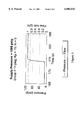
- FIG. 3 is a plot illustrating the predicted characteristics of a modeled regulator according to the present invention with a proportional controller
- FIG. 4 is a view like FIG. 3 with a proportional-integral-derivative controller
- FIG. 5 is a view like FIG. 3 of a prototype regulator.
- FIG. 6 is a view like FIG. 5 with a proportional-integral control.
- an electronic regulator 10 that includes a regulator housing 12 with a gas inlet 14 for receiving gas at a supply pressure from a gas source 15 and an outlet 16 for discharging gas at a controlled pressure to the fuel system of an internal combustion engine 17.
- a high speed solenoid valve 18 is coupled to the housing. It is normally closed and blocks flow from the gas inlet to the gas outlet.
- the regulator is preferably built into the gas source 15 to eliminate any high pressure gas line between the two components.
- a pressure transducer 20 is mounted on the housing to monitor the gas pressure downstream from the solenoid valve.
- the signal from the pressure transducer is delivered to an analog to digital converter 22 which serves as an interface for the pressure measurement.
- the output from the converter is delivered to a microprocessor 24 which in turn controls operation of the solenoid valve 18.
- the microprocessor contains algorithms that provide for proportional-integral-derivative control of the control system. Proportional control allows for fast response. Integral control reduces the steady state error between the set point pressure and the measured pressure to zero. Derivative control increases the response to rapid changes in flow demand.
- Instrumentation 26 on the engine monitors engine control parameters that are measures of the fuel demand of the engine. The output from this instrumentation is also delivered to the microprocessor which varies the operation of the solenoid to meet the engine fuel demand.
- the pressure control model is based on the solution to the transient equations for the conservation of mass and energy in a control volume. Models were also developed for pulse-width modulation, fluid injection into a control volume, PID control, and heat transfer from the walls. A frequency modulation model was also developed.
- the regulator pressure chamber can be represented by a control volume of volume, V.
- the fluid has a mass, M, and energy, E, as shown in FIG. 2.
- Natural gas injection is represented by the inlet mass flow, m s , through the cross-sectional area of the throat, A t .
- the outlet mass flow rate or load flow rate, m 1 is represented by a look up table of flow rates in time.
- m 1 load mass flow rate (kg/s)
- N isentropic efficiency
- Equation 1 The following first-order integration routine was used for Equation 1:
- Equation 2 A similar integration scheme was used for Equation 2.
- a t area of the throat (m 2 )
- h heat transfer coefficient of the wall (W/m 2 /K)
- a w surface area of the wall (m 2 )
- ⁇ m time constant of the pressure transducer(s)
- Pulse width and frequency modulation are used in the model to control the outlet pressure base on the following relationships:
- T b base pulse(s)
- f b is also modified according to the following equation:
- the frequency of injection can be made proportional to engine speed, obviating the need for frequency modulation according to the above equations.
- the model was run to compare proportional control with proportional-integral-derivative control for the electronic regulator.
- the flow rate was increased from 0.1 to 1.0 g/s at the 10 second mark as shown in FIG. 2.
- the controller increased the pulse width from 3 ms to 8.5 ms.
- the model predicts a droop in pressure of about 100 kPa (14 psig) for proportional control.
- the droop is reduced to about 15 kPa (2 psig) for the proportional-integral-derivative controller shown in FIG. 4.
- Similar improvements were found in a prototype bench test of the regulator as illustrated in FIGS. 5 and 6. In this case, the improved results were achieved using a proportional-integral controller.
- An electronic pressure regulator according to the present invention may be used as a separate system similar to conventional regulators, or it may be a system integrated into the central computer of a motor vehicle.
- the electronic regulator can be configured to permit electronic control of the set-point pressure of the regulator to increase the dynamic range of the fuel system.
Abstract
Description
M.sup.t+1 =M.sup.t +(m.sub.s -m.sub.1)Δt (3)
P=zρRT
q=hA.sub.w (T.sub.w -T)
T.sub.i =T.sub.b (1+F.sub.af)
f=f.sub.b (1+F.sub.af)
f=f.sub.b +f.sub.0
Claims (11)
Applications Claiming Priority (2)
| Application Number | Priority Date | Filing Date | Title |
|---|---|---|---|
| GB9612224A GB2316773B (en) | 1996-06-12 | 1996-06-12 | Electronic gas regulator |
| GB961224 | 1996-10-12 |
Publications (1)
| Publication Number | Publication Date |
|---|---|
| US6003543A true US6003543A (en) | 1999-12-21 |
Family
ID=10795130
Family Applications (1)
| Application Number | Title | Priority Date | Filing Date |
|---|---|---|---|
| US08/873,160 Expired - Lifetime US6003543A (en) | 1996-06-12 | 1997-06-11 | Electronic gas regulator |
Country Status (2)
| Country | Link |
|---|---|
| US (1) | US6003543A (en) |
| GB (1) | GB2316773B (en) |
Cited By (30)
| Publication number | Priority date | Publication date | Assignee | Title |
|---|---|---|---|---|
| WO2001059537A1 (en) | 2000-02-09 | 2001-08-16 | Saskatchewan Research Council | High volume electronic gas regulator |
| US6308725B1 (en) * | 2000-06-10 | 2001-10-30 | Delphi Technologies, Inc. | Apparatus for controlling hydraulic fluid pressure |
| US6402042B1 (en) | 2000-11-29 | 2002-06-11 | Blue Earth Research | Uniform temperature control system |
| US20040094737A1 (en) * | 2002-11-18 | 2004-05-20 | Michael Yeh | Pressure regulating device |
| US20040139951A1 (en) * | 2003-01-16 | 2004-07-22 | Fisher C. Ross | Emission control valve for gas-fueled engines |
| US20040216742A1 (en) * | 2003-05-02 | 2004-11-04 | James Talty | Oxygen supply system having a central flow control unit |
| DE102004049662A1 (en) * | 2004-10-12 | 2006-04-20 | Nanion Technologies Gmbh | Device for application of over- and under-pressure esp. for micro-fluidic experiments, uses membrane valve only partly opening during switching above specified frequencies |
| US20060231085A1 (en) * | 2005-04-15 | 2006-10-19 | General Electric Company | Method and apparatus of assembling cooking appliances |
| US20070144498A1 (en) * | 2005-12-28 | 2007-06-28 | Delphi Technologies, Inc. | Cooling apparatus and method using low fluid flow rates |
| US20070144597A1 (en) * | 2003-08-04 | 2007-06-28 | L'air Liquide, Societe Anonyme A Directoire Et Conseil De Surveillance Pour L'etude | Circuit for supplying oxygen to aircraft passengers |
| US20090065720A1 (en) * | 2006-04-24 | 2009-03-12 | Georg Bachmaier | Pressure Regulator for Gaseous Media |
| US7505818B1 (en) * | 2001-09-07 | 2009-03-17 | Siemens Energy & Automation, Inc. | Converter method, system and apparatus |
| US20090088950A1 (en) * | 2007-09-27 | 2009-04-02 | Continental Controls Corporation | Fuel control system and method for gas engines |
| US7922833B2 (en) | 2008-08-05 | 2011-04-12 | Kennametal Inc. | Gas regulator for thermal energy machining |
| US20110114196A1 (en) * | 2009-06-17 | 2011-05-19 | Jason Lall | Electronic pressure regulator |
| US20130037126A1 (en) * | 2011-08-10 | 2013-02-14 | Ableprint Technology Co., Ltd. | Gas concentration control device for pressure vessel |
| US20130118596A1 (en) * | 2011-11-12 | 2013-05-16 | Thomas Neal Horsky | Gas flow system, device and method |
| US20130186475A1 (en) * | 2012-01-19 | 2013-07-25 | Idexx Laboratories Inc. | Fluid pressure control device for an analyzer |
| US20130333774A1 (en) * | 2010-11-29 | 2013-12-19 | Air Products And Chemicals, Inc. | Method of and apparatus for measuring the pressure of a gas |
| CN105607659A (en) * | 2014-11-19 | 2016-05-25 | 中国航空工业集团公司西安飞机设计研究所 | Digital high-altitude chamber flow control device |
| US9441997B2 (en) | 2012-05-24 | 2016-09-13 | Air Products And Chemicals, Inc. | Method of, and apparatus for, measuring the physical properties of two-phase fluids |
| US9448090B2 (en) | 2012-05-24 | 2016-09-20 | Air Products And Chemicals, Inc. | Method of, and apparatus for, measuring the mass flow rate of a gas |
| US9448094B2 (en) | 2010-11-29 | 2016-09-20 | Air Products And Chemicals, Inc. | Method of and apparatus for measuring the mass flow rate of a gas |
| US9459191B2 (en) | 2010-11-29 | 2016-10-04 | Air Products And Chemicals, Inc. | Method of and apparatus for measuring the molecular weight of a gas |
| US9581297B2 (en) | 2012-05-24 | 2017-02-28 | Air Products And Chemicals, Inc. | Method of, and apparatus for, measuring the true contents of a cylinder of gas under pressure |
| US9624863B1 (en) | 2015-10-28 | 2017-04-18 | Caterpillar Inc. | System and method for supplying fuel to engine |
| US9690304B2 (en) | 2012-05-24 | 2017-06-27 | Air Products And Chemicals, Inc. | Method of, and apparatus for, providing a gas mixture |
| US9804010B2 (en) | 2012-05-24 | 2017-10-31 | Air Products And Chemicals, Inc. | Method of, and apparatus for, regulating the mass flow rate of a gas |
| US9870007B2 (en) | 2012-05-24 | 2018-01-16 | Air Products And Chemicals, Inc. | Method of, and apparatus for, providing a gas mixture |
| US20190001282A1 (en) * | 2017-06-30 | 2019-01-03 | Pulsair Systems, Inc. | Control circuit for stopping the flow of fluid in a primary circuit, and related methods and devices |
Families Citing this family (1)
| Publication number | Priority date | Publication date | Assignee | Title |
|---|---|---|---|---|
| WO2001004718A1 (en) * | 1999-07-09 | 2001-01-18 | Tescom Corporation | Electronic controlled pressure regulator system |
Citations (14)
| Publication number | Priority date | Publication date | Assignee | Title |
|---|---|---|---|---|
| US3800794A (en) * | 1970-12-30 | 1974-04-02 | Ivac Corp | Method and apparatus for fluid flow control |
| US4373549A (en) * | 1979-02-12 | 1983-02-15 | Hewlett-Packard Company | Mass flow/pressure control system |
| GB2121563A (en) * | 1982-06-03 | 1983-12-21 | Gema Ransburg Ag | Pressure regulating apparatus for gaseous and liquid flow media |
| US4436110A (en) * | 1982-03-25 | 1984-03-13 | Landi Den Hartog Bv | Pressure regulating systems |
| US4513728A (en) * | 1982-01-15 | 1985-04-30 | Solex (U.K.) Limited | Air/fuel induction system for spark ignition internal combustion engines, and electromagnetic valves |
| US4690163A (en) * | 1983-09-27 | 1987-09-01 | Georg Fischer Aktiengesellschaft | Method and apparatus for regulating fluid flow |
| US4892286A (en) * | 1988-01-25 | 1990-01-09 | Eaton Corporation | Fluid control device |
| US4917349A (en) * | 1989-03-29 | 1990-04-17 | Halliburton Company | Valve, and set point pressure controller utilizing the same |
| EP0420599A2 (en) * | 1989-09-29 | 1991-04-03 | Ortech Corporation | Flow control system |
| US5020564A (en) * | 1989-06-29 | 1991-06-04 | Allied-Signal Inc. | Doser system for regulating pressure in a control chamber of a test stand |
| US5105790A (en) * | 1990-12-21 | 1992-04-21 | Nye Jr Dudley D | Current controlled fluid bleed |
| US5343847A (en) * | 1993-09-13 | 1994-09-06 | Pacer Industries, Inc. | Electronic gaseous fuel injection system |
| GB2295249A (en) * | 1994-11-02 | 1996-05-22 | Druck Ltd | Pressure controller |
| US5673673A (en) * | 1996-04-30 | 1997-10-07 | Servojet Products International | Method and apparatus for the high Mach injection of a gaseous fuel into an internal combustion engine |
Family Cites Families (1)
| Publication number | Priority date | Publication date | Assignee | Title |
|---|---|---|---|---|
| IE43437B1 (en) * | 1976-01-03 | 1981-02-25 | Laser Grade Ireland Ltd | Improvements relating to fluid regulating systems |
-
1996
- 1996-06-12 GB GB9612224A patent/GB2316773B/en not_active Expired - Lifetime
-
1997
- 1997-06-11 US US08/873,160 patent/US6003543A/en not_active Expired - Lifetime
Patent Citations (14)
| Publication number | Priority date | Publication date | Assignee | Title |
|---|---|---|---|---|
| US3800794A (en) * | 1970-12-30 | 1974-04-02 | Ivac Corp | Method and apparatus for fluid flow control |
| US4373549A (en) * | 1979-02-12 | 1983-02-15 | Hewlett-Packard Company | Mass flow/pressure control system |
| US4513728A (en) * | 1982-01-15 | 1985-04-30 | Solex (U.K.) Limited | Air/fuel induction system for spark ignition internal combustion engines, and electromagnetic valves |
| US4436110A (en) * | 1982-03-25 | 1984-03-13 | Landi Den Hartog Bv | Pressure regulating systems |
| GB2121563A (en) * | 1982-06-03 | 1983-12-21 | Gema Ransburg Ag | Pressure regulating apparatus for gaseous and liquid flow media |
| US4690163A (en) * | 1983-09-27 | 1987-09-01 | Georg Fischer Aktiengesellschaft | Method and apparatus for regulating fluid flow |
| US4892286A (en) * | 1988-01-25 | 1990-01-09 | Eaton Corporation | Fluid control device |
| US4917349A (en) * | 1989-03-29 | 1990-04-17 | Halliburton Company | Valve, and set point pressure controller utilizing the same |
| US5020564A (en) * | 1989-06-29 | 1991-06-04 | Allied-Signal Inc. | Doser system for regulating pressure in a control chamber of a test stand |
| EP0420599A2 (en) * | 1989-09-29 | 1991-04-03 | Ortech Corporation | Flow control system |
| US5105790A (en) * | 1990-12-21 | 1992-04-21 | Nye Jr Dudley D | Current controlled fluid bleed |
| US5343847A (en) * | 1993-09-13 | 1994-09-06 | Pacer Industries, Inc. | Electronic gaseous fuel injection system |
| GB2295249A (en) * | 1994-11-02 | 1996-05-22 | Druck Ltd | Pressure controller |
| US5673673A (en) * | 1996-04-30 | 1997-10-07 | Servojet Products International | Method and apparatus for the high Mach injection of a gaseous fuel into an internal combustion engine |
Cited By (42)
| Publication number | Priority date | Publication date | Assignee | Title |
|---|---|---|---|---|
| US6758233B2 (en) | 2000-02-09 | 2004-07-06 | Saskatchewan Research Council | High volume electronic gas regulator |
| WO2001059537A1 (en) | 2000-02-09 | 2001-08-16 | Saskatchewan Research Council | High volume electronic gas regulator |
| US6308725B1 (en) * | 2000-06-10 | 2001-10-30 | Delphi Technologies, Inc. | Apparatus for controlling hydraulic fluid pressure |
| US6402042B1 (en) | 2000-11-29 | 2002-06-11 | Blue Earth Research | Uniform temperature control system |
| US7505818B1 (en) * | 2001-09-07 | 2009-03-17 | Siemens Energy & Automation, Inc. | Converter method, system and apparatus |
| US20040094737A1 (en) * | 2002-11-18 | 2004-05-20 | Michael Yeh | Pressure regulating device |
| US20040139951A1 (en) * | 2003-01-16 | 2004-07-22 | Fisher C. Ross | Emission control valve for gas-fueled engines |
| US6978774B2 (en) | 2003-01-16 | 2005-12-27 | Continental Controls Corporation | Emission control valve for gas-fueled engines |
| US7341072B2 (en) | 2003-05-02 | 2008-03-11 | Carleton Technologies, Inc. | Oxygen supply system having a central flow control unit |
| US20040216742A1 (en) * | 2003-05-02 | 2004-11-04 | James Talty | Oxygen supply system having a central flow control unit |
| US20070144597A1 (en) * | 2003-08-04 | 2007-06-28 | L'air Liquide, Societe Anonyme A Directoire Et Conseil De Surveillance Pour L'etude | Circuit for supplying oxygen to aircraft passengers |
| US9272786B2 (en) * | 2003-08-04 | 2016-03-01 | L'Air Liquide Société Anonyme Pour L'Étude Et L'Exploitation Des Procedes Georges Claude | Circuit for supplying oxygen to aircraft passengers |
| DE102004049662A1 (en) * | 2004-10-12 | 2006-04-20 | Nanion Technologies Gmbh | Device for application of over- and under-pressure esp. for micro-fluidic experiments, uses membrane valve only partly opening during switching above specified frequencies |
| US20060231085A1 (en) * | 2005-04-15 | 2006-10-19 | General Electric Company | Method and apparatus of assembling cooking appliances |
| US7748374B2 (en) | 2005-04-15 | 2010-07-06 | General Electric Company | Method and apparatus of assembling cooking appliances |
| US20070144498A1 (en) * | 2005-12-28 | 2007-06-28 | Delphi Technologies, Inc. | Cooling apparatus and method using low fluid flow rates |
| US8096522B2 (en) | 2006-04-24 | 2012-01-17 | Siemens Aktiengesellschaft | Pressure regulator for gaseous media |
| US20090065720A1 (en) * | 2006-04-24 | 2009-03-12 | Georg Bachmaier | Pressure Regulator for Gaseous Media |
| US8005603B2 (en) | 2007-09-27 | 2011-08-23 | Continental Controls Corporation | Fuel control system and method for gas engines |
| US20090088950A1 (en) * | 2007-09-27 | 2009-04-02 | Continental Controls Corporation | Fuel control system and method for gas engines |
| US7922833B2 (en) | 2008-08-05 | 2011-04-12 | Kennametal Inc. | Gas regulator for thermal energy machining |
| US20110114196A1 (en) * | 2009-06-17 | 2011-05-19 | Jason Lall | Electronic pressure regulator |
| US9239271B2 (en) * | 2010-11-29 | 2016-01-19 | Air Products And Chemicals, Inc. | Method of and apparatus for measuring the pressure of a gas |
| US9459191B2 (en) | 2010-11-29 | 2016-10-04 | Air Products And Chemicals, Inc. | Method of and apparatus for measuring the molecular weight of a gas |
| US9448094B2 (en) | 2010-11-29 | 2016-09-20 | Air Products And Chemicals, Inc. | Method of and apparatus for measuring the mass flow rate of a gas |
| US20130333774A1 (en) * | 2010-11-29 | 2013-12-19 | Air Products And Chemicals, Inc. | Method of and apparatus for measuring the pressure of a gas |
| US20130037126A1 (en) * | 2011-08-10 | 2013-02-14 | Ableprint Technology Co., Ltd. | Gas concentration control device for pressure vessel |
| US8695623B2 (en) * | 2011-08-10 | 2014-04-15 | Ableprint Technology Co., Ltd. | Gas concentration control device for pressure vessel |
| US20130118609A1 (en) * | 2011-11-12 | 2013-05-16 | Thomas Neil Horsky | Gas flow device |
| US20130118596A1 (en) * | 2011-11-12 | 2013-05-16 | Thomas Neal Horsky | Gas flow system, device and method |
| US20130186475A1 (en) * | 2012-01-19 | 2013-07-25 | Idexx Laboratories Inc. | Fluid pressure control device for an analyzer |
| US9151731B2 (en) * | 2012-01-19 | 2015-10-06 | Idexx Laboratories Inc. | Fluid pressure control device for an analyzer |
| US9581297B2 (en) | 2012-05-24 | 2017-02-28 | Air Products And Chemicals, Inc. | Method of, and apparatus for, measuring the true contents of a cylinder of gas under pressure |
| US9448090B2 (en) | 2012-05-24 | 2016-09-20 | Air Products And Chemicals, Inc. | Method of, and apparatus for, measuring the mass flow rate of a gas |
| US9441997B2 (en) | 2012-05-24 | 2016-09-13 | Air Products And Chemicals, Inc. | Method of, and apparatus for, measuring the physical properties of two-phase fluids |
| US9690304B2 (en) | 2012-05-24 | 2017-06-27 | Air Products And Chemicals, Inc. | Method of, and apparatus for, providing a gas mixture |
| US9804010B2 (en) | 2012-05-24 | 2017-10-31 | Air Products And Chemicals, Inc. | Method of, and apparatus for, regulating the mass flow rate of a gas |
| US9870007B2 (en) | 2012-05-24 | 2018-01-16 | Air Products And Chemicals, Inc. | Method of, and apparatus for, providing a gas mixture |
| CN105607659A (en) * | 2014-11-19 | 2016-05-25 | 中国航空工业集团公司西安飞机设计研究所 | Digital high-altitude chamber flow control device |
| US9624863B1 (en) | 2015-10-28 | 2017-04-18 | Caterpillar Inc. | System and method for supplying fuel to engine |
| US20190001282A1 (en) * | 2017-06-30 | 2019-01-03 | Pulsair Systems, Inc. | Control circuit for stopping the flow of fluid in a primary circuit, and related methods and devices |
| US10940447B2 (en) * | 2017-06-30 | 2021-03-09 | Pulsair Systems, Inc. | Control circuit for stopping the flow of fluid in a primary circuit, and related methods and devices |
Also Published As
| Publication number | Publication date |
|---|---|
| GB9612224D0 (en) | 1996-08-14 |
| GB2316773A (en) | 1998-03-04 |
| GB2316773B (en) | 1999-09-29 |
Similar Documents
| Publication | Publication Date | Title |
|---|---|---|
| US6003543A (en) | Electronic gas regulator | |
| US4452207A (en) | Fuel/air ratio control apparatus for a reciprocating aircraft engine | |
| CA1306908C (en) | Arrangement for the metering of fuel and metering device therefor | |
| JP2680176B2 (en) | Method and apparatus for controlling fluid flow rate | |
| US5150690A (en) | Flow control system | |
| US4337616A (en) | Fuel air ratio controlled fuel splitter | |
| EP1264228B1 (en) | High volume electronic gas regulator | |
| US4449509A (en) | Gaseous fuel carburetion | |
| US3949714A (en) | Fuel-air metering and induction system | |
| US4541397A (en) | Gaseous fuel carburetion system | |
| US8286611B1 (en) | Electronic pressure regulator | |
| US8176897B1 (en) | Electronic pressure regulator | |
| US4421280A (en) | Fuel injector | |
| US4040408A (en) | System for reducing toxic components in the exhaust gas of an internal combustion engine | |
| US6148601A (en) | Engine fuel control system and method | |
| US8136506B1 (en) | Electronic pressure regulator | |
| US4421089A (en) | Fuel metering apparatus | |
| JPS63131844A (en) | Revolving speed control device for internal combustion engine | |
| US4167169A (en) | Fuel flow control system | |
| CA2207497C (en) | Electronic gas regulator | |
| US5357938A (en) | Exhaust emission control in gaseous fuelled engines | |
| US4188919A (en) | Fluid regulating systems | |
| US4436110A (en) | Pressure regulating systems | |
| EP0182952B1 (en) | Equipment suitable for feeding in internal combustion engine with air-l.p.g or air-methane mixture and device to regulate the strength of the mixture delivered by this equipment | |
| US4353338A (en) | Engine idle air valve means and system |
Legal Events
| Date | Code | Title | Description |
|---|---|---|---|
| AS | Assignment |
Owner name: GAS TECHNOLOGY CANADA, CANADA Free format text: ASSIGNMENT OF ASSIGNORS INTEREST;ASSIGNORS:SULATISKY, MICHAEL T.;WHITE, NICHOLAS P.;REEL/FRAME:008622/0057;SIGNING DATES FROM 19970530 TO 19970604 |
|
| STCF | Information on status: patent grant |
Free format text: PATENTED CASE |
|
| AS | Assignment |
Owner name: HER MAJESTY THE QUEEN IN RIGHT OF CANADA AS REPRES Free format text: ASSIGNMENT OF ASSIGNORS INTEREST;ASSIGNOR:GAS TECHNOLOGY CANADA;REEL/FRAME:012312/0636 Effective date: 20011005 |
|
| FEPP | Fee payment procedure |
Free format text: PAT HOLDER NO LONGER CLAIMS SMALL ENTITY STATUS, ENTITY STATUS SET TO UNDISCOUNTED (ORIGINAL EVENT CODE: STOL); ENTITY STATUS OF PATENT OWNER: SMALL ENTITY |
|
| AS | Assignment |
Owner name: SASKATCHWEAN RESEARCH COUNCIL, CANADA Free format text: ASSIGNMENT OF ASSIGNORS INTEREST;ASSIGNOR:HER MAJESTY THE QUEEN IN RIGHT OF CANADA AS REPRESENTED BY THE MINISTER OF NATURAL RESOURCES;REEL/FRAME:013821/0756 Effective date: 20030127 |
|
| FPAY | Fee payment |
Year of fee payment: 4 |
|
| SULP | Surcharge for late payment | ||
| REMI | Maintenance fee reminder mailed | ||
| FPAY | Fee payment |
Year of fee payment: 8 |
|
| FEPP | Fee payment procedure |
Free format text: PAT HOLDER CLAIMS SMALL ENTITY STATUS, ENTITY STATUS SET TO SMALL (ORIGINAL EVENT CODE: LTOS); ENTITY STATUS OF PATENT OWNER: SMALL ENTITY |
|
| FPAY | Fee payment |
Year of fee payment: 12 |