US6004140A - Female electric connector - Google Patents
Female electric connector Download PDFInfo
- Publication number
- US6004140A US6004140A US09/134,755 US13475598A US6004140A US 6004140 A US6004140 A US 6004140A US 13475598 A US13475598 A US 13475598A US 6004140 A US6004140 A US 6004140A
- Authority
- US
- United States
- Prior art keywords
- terminal
- circuit board
- female connector
- slits
- base portion
- Prior art date
- Legal status (The legal status is an assumption and is not a legal conclusion. Google has not performed a legal analysis and makes no representation as to the accuracy of the status listed.)
- Expired - Lifetime
Links
Images


Classifications
-
- H—ELECTRICITY
- H01—ELECTRIC ELEMENTS
- H01R—ELECTRICALLY-CONDUCTIVE CONNECTIONS; STRUCTURAL ASSOCIATIONS OF A PLURALITY OF MUTUALLY-INSULATED ELECTRICAL CONNECTING ELEMENTS; COUPLING DEVICES; CURRENT COLLECTORS
- H01R12/00—Structural associations of a plurality of mutually-insulated electrical connecting elements, specially adapted for printed circuits, e.g. printed circuit boards [PCB], flat or ribbon cables, or like generally planar structures, e.g. terminal strips, terminal blocks; Coupling devices specially adapted for printed circuits, flat or ribbon cables, or like generally planar structures; Terminals specially adapted for contact with, or insertion into, printed circuits, flat or ribbon cables, or like generally planar structures
- H01R12/70—Coupling devices
- H01R12/71—Coupling devices for rigid printing circuits or like structures
- H01R12/712—Coupling devices for rigid printing circuits or like structures co-operating with the surface of the printed circuit or with a coupling device exclusively provided on the surface of the printed circuit
- H01R12/714—Coupling devices for rigid printing circuits or like structures co-operating with the surface of the printed circuit or with a coupling device exclusively provided on the surface of the printed circuit with contacts abutting directly the printed circuit; Button contacts therefore provided on the printed circuit
-
- H—ELECTRICITY
- H01—ELECTRIC ELEMENTS
- H01R—ELECTRICALLY-CONDUCTIVE CONNECTIONS; STRUCTURAL ASSOCIATIONS OF A PLURALITY OF MUTUALLY-INSULATED ELECTRICAL CONNECTING ELEMENTS; COUPLING DEVICES; CURRENT COLLECTORS
- H01R12/00—Structural associations of a plurality of mutually-insulated electrical connecting elements, specially adapted for printed circuits, e.g. printed circuit boards [PCB], flat or ribbon cables, or like generally planar structures, e.g. terminal strips, terminal blocks; Coupling devices specially adapted for printed circuits, flat or ribbon cables, or like generally planar structures; Terminals specially adapted for contact with, or insertion into, printed circuits, flat or ribbon cables, or like generally planar structures
- H01R12/70—Coupling devices
- H01R12/7082—Coupling device supported only by cooperation with PCB
-
- H—ELECTRICITY
- H01—ELECTRIC ELEMENTS
- H01R—ELECTRICALLY-CONDUCTIVE CONNECTIONS; STRUCTURAL ASSOCIATIONS OF A PLURALITY OF MUTUALLY-INSULATED ELECTRICAL CONNECTING ELEMENTS; COUPLING DEVICES; CURRENT COLLECTORS
- H01R13/00—Details of coupling devices of the kinds covered by groups H01R12/70 or H01R24/00 - H01R33/00
- H01R13/73—Means for mounting coupling parts to apparatus or structures, e.g. to a wall
- H01R13/74—Means for mounting coupling parts in openings of a panel
- H01R13/741—Means for mounting coupling parts in openings of a panel using snap fastening means
- H01R13/743—Means for mounting coupling parts in openings of a panel using snap fastening means integral with the housing
Definitions
- the present invention relates to a connector applicable to an analogue type indicating instrument and other electric devices.
- a circuit board for driving a step-motor and an external circuit board are disposed in parallel with each other and connected by a wire harness to each other.
- connection is carried out by soldering or screw-fastening the ends of the wire harness to the circuit boards. Once the circuit boards are connected by soldering or screw-fastening, it takes time to disconnect one from the other.
- the present invention has an object of providing an improved connector which is easily to connect two circuits board each other or disconnect one circuit board from the other.
- a female connector to be coupled with a male connector of an electric device and an external circuit board is composed of a case member to be inserted into a coupling hole of the circuit board, a pedestal portion extending outward from the case member, a plurality of terminal members disposed in the case member, and at least a pair of projection members extending from opposite sides of the pedestal portion toward the coupling hole of the circuit board.
- one of walls of the case member has a plurality of parallel slits extending in the direction perpendicular to the circuit board, and the pedestal member has a plurality of parallel grooves extending in the longitudinal direction to be connected to the plurality of slits respectively.
- each of the terminal members has a base portion inserted in one of the grooves, a first terminal portion extending from the base portion to be inserted to one of the slits and a second terminal portion extending from the base portion toward the circuit board, and the first and second terminal portions are in contact with terminal plates of the electric device and the circuit board under pressure respectively when the female connector is coupled with the male connector and the circuit board.
- the female connector can be coupled with or removed from the male connector easily without any additional member or tool.
- the above female connector may have a plurality of other terminal members disposed in the case member symmetrically to first-said terminal members.
- the above female connector may also have an outside member for accommodating the case member to be movable within a suitable amount of play.
- the case member has a projection member and that the outside member has holes in engagement with the projection member.
- the pedestal portion has a hook member and a wall member disposed in the grooves and that the base portion of the terminal members has an edge portion held in the grooves retained by the hook member and the wall member.
- FIG. 1 is an exploded perspective view of an indicating instrument, an external circuit board and a female connector according to an embodiment of the invention
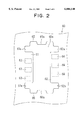
- FIG. 2 is a plan view illustrating a main portion of an external circuit board to be connected to the connector shown in FIG. 1;
- FIG. 3 is an exploded perspective view of the female connector according to the embodiment.
- FIG. 4 is a cross-sectional side view of a portion of the female connector illustrated in FIG. 6 cut along line 4--4;
- FIG. 5 is a cross-sectional side view of a portion of the female connector illustrated in FIG. 6 cut along line 5--5;
- FIG. 6 is a plan view of the female connector illustrated in FIG. 1;
- FIG. 7 is a left side view of the female connector illustrated in FIG. 6;
- FIG. 8 is a bottom view of the female connector illustrated in FIG. 6;
- FIG. 9 is a back view of the female connector illustrated in FIG. 6.
- FIGS. 1-9 A female connector according to a preferred embodiment of the present invention is described with reference to FIGS. 1-9.
- an analogue type speed meter has step motor M which is fixed to the back of a dial plate (not shown).
- Step motor M has rotary shaft 10 carrying luminous pointer 20 on one end thereof.
- Luminous pointer 20 has a light emitting diode (not shown) at the base thereof and emits light from a slit formed on the upper surface thereof to display a measurement.
- Step motor M has cylindrical housing 30, which has an opening formed on the outer periphery thereof.
- a terminal cover 40 is fixed to inner opening 41 of terminal cover 40 made of thermoplastic resin such as polybutylene terephtalate.
- Terminal cover 40 accommodates a connector made of insulating resinous material (not shown) that holds two pair of terminals 111, 112 for energizing the light emitting diode and two pair of terminals 113, 114 for energizing step motor M.
- the pair of terminals 111 is connected to the anode of the light emitting diode, and the pair of terminals 112 is connected to the cathode thereof.
- the pairs of terminals are respectively connected to input terminals for two-phase windings of step motor M.
- Circuit board 50 for step motor M is fixed to outside opening 42 of terminal cover 40.
- Circuit board 50 has a pair of fixing holes 51 and terminal cover 40 has a pair of projections 42a extending therefrom to be fitted into the pair of fixing holes 51. Projections 42a are thermally welded to fixing holes 51.
- Circuit board 50 has four slits at upper portions thereof to which terminals 111, 112 are inserted and four round holes at central portions thereof to which terminals 113, 114 are inserted as illustrated in FIG. 1.
- Circuit board 50 also has flat male connector portion 52 extending downward from an opening (not shown) of the bottom of casing.
- Three terminal plates 53 are fixed on the front side of male connector portion 52 and three terminal plates 54 are fixed on the backside thereof. Two of three terminal plate 53 are respectively connected to the pair of terminal 113 via a circuit pattern (not shown), and two of three terminal plates 54 are respectively connected to the pair of terminal 114 via another circuit pattern (not shown). The rest of terminal plates 53 is connected to the pair of terminals 111 via a circuit pattern (not shown), and the rest of terminal plates 54 are connected to the pair of terminals 112 via another circuit pattern (not shown).
- Circuit board 60 connects an external circuit (not shown) through female connector C, connector portions of both circuit board 50 and terminal cover 40 to the light emitting diode and the stator winding (phase windings).
- Circuit board 60 is disposed under the bottom of the casing to be perpendicular to male connector portion 52.
- Circuit board 60 has generally rectangular opening 60a, through which male connector portion 52 and female connector C are coupled and male connector portion 52 is connected to the external circuit.
- Coupling hole 60a has a pair of side-convex portions 61, 62 formed on the opposite sides thereof and a pair of end-convex portions 65a, 66a formed on the opposite ends thereof as shown in FIG. 2.
- Three terminal plates 63 are formed on the back surface of side-convex portion 61 of coupling hole 60a, and three terminal plates 64 are formed on the back surface of opposite side-convex portion 62 thereof.
- Each of terminal plates 63 shifts longitudinally (downward in FIG. 2) from corresponding one of terminal plate 64 by a width of one of terminal plates 64.
- a pair of side-concave portions 61a is formed at the opposite ends of side-convex portion 61, and a pair of side-concave portions 62a is formed at the opposite ends of side-convex portion 62.
- a pair of end-concave portions 65 is formed on the opposite sides of end-convex portion 65a, and a pair of end-concave portions 66 is formed on the opposite sides of end-convex portion 66a.
- Female connector C is composed of outside connector member 70 and inside connector member 80, both made of elastic insulation material, as shown in FIG. 1 and FIG. 3.
- Outside connector member 70 has a pair of end walls 72, a pair of side walls 73 and four rectangular poles 71 extending upward from the respective corners of a rectangular opening surrounded by walls 72, 73 as shown in FIG. 3.
- Four rectangular poles 71 are to be fitted into side-concave portions 61a, 62a respectively to be elastically held therein.
- End walls 72 have engagement holes 72a respectively. When outside connector member 70 is inserted into coupling hole 60a of circuit board 60, end walls 72 bend elastically until end-convex portions 65a, 66a are fitted to the pair of engagement holes 72a.
- Female connector member 80A is composed of rectangular female connector member 80A, a group of three terminal members 80B and another group of three terminal members 80C.
- Female connector member 80A is made of insulating resinous material and has case portion 80a and pedestal portion 80b extending outward from opposite side walls of case portion 80a to form a reversed T-shape in cross-section as shown in FIG. 3.
- Female connector porion 80a has six parallel slits 81a, 82a on opposite side walls 81, 82 respectively as shown in FIGS. 4, 5 and 7. Each of slits 81a is formed to be opposed to one of slits 82a as shown in FIG. 4.
- Pedestal portion 80b has three grooves 83a extending from one side thereof and three grooves 83b extending from the opposite side thereof, both, in the direction perpendicular to side walls 81, 82. As shown in FIG. 1 and FIG. 5, each of grooves 83a, 83b has narrower portion at the bottom thereof.
- each of three grooves 83a is connected with every second of slits 81a, 82a and each of three grooves 83b is connected with the rest of slits 81a, 82a.
- each of grooves 83b extends left from the right side of pedestal portion 80b, and each of grooves 83a extends right from the left side of pedestal portion 80b.
- pedestal portion 80a has a pair of tapered projections 84a, 84b at the opposite sides thereof.
- projection 84a extends from a portion between lower two grooves 83a and engages rectangular holes 73a formed in left side wall 73 of outside connector member 70
- projection 84b extends from a portion between upper two grooves 83b and engages rectangular hole 73a formed in the right side wall 73.
- the bottom area of outside connector member 70 is arranged to be larger than the bottom area of pedestal portion 80b thereby forming a suitable amount of play, so that pedestal portion 80b can move within some distance (e.g. 2 mm).
- the cross-sectional area of projections 84a, 84b is also arranged to be smaller than the open area of rectangular holes 73a, thereby forming a suitable amount of play, so that pedestal portion 80b can move along side walls 73 of outside connector member 70 within some distance (e.g. 2 mm).
- Each of terminal members 80B is made of tinned phosphor bronze and, as shown in FIG. 3, is composed of flat base portion 85, upright first terminal portion 86a extending upward from base portion 85 and bowed (or J-shaped) second terminal portion 86b extending parallelly from base portion 85.
- Each of terminal members 80C is the same in material and structure, which is composed of flat base portion 87, upright first terminal portion 88a and bowed second terminal 88b. As shown in FIGS. 4 and 6, lowermost one of base portions 87 is press-fitted to the narrower portion of one of grooves 83 so that the left side surface of edge 87a engages the left wall of groove 83b and upper portion of edge 87a engages hook 89b of hook member 89a extending from the left end of pedestal portion 80b.
- first terminal portions 88a is inserted into the lowermost one of slits 81a, and the lowermost one of second terminal portions 88b extends toward the right opening of groove 83b.
- First terminal portion 88a and second terminal portion 88b have respective hook-shaped portion 88c, 88d at the edge thereof as shown in FIGS. 3 and 4.
- hook-shaped portion 88c extends into the inside of case portion 80a toward right side wall 82, and hook-shaped portion 88d projects upward from groove 83b.
- Hook member 89a extends from the left side wall of the lowermost one of grooves 83b in the longitudinal direction of groove 83b with hook 89b down.
- terminal members 80C have the same structure as the above.
- Terminal members 80B have also the same structure except that terminal members 80C are installed in case portion 80a symmetrically to terminal members 80B.
- FIG. 1 when female connector C is inserted into coupling hole 60a of circuit board 60 as indicated by an arrow, four rectangular poles 71 are elastically fitted to side concave portions 61a, 62a. Opposite end walls 72 are inserted to coupling hole 60a to bend along the inner peripheries of end-convex portions 65a, 66a until end-convex portions 65a, 66a engage engagement holes 72a.
- male connector portion 52 of circuit board 50 is fitted to case portion 80a of inside connector member 80. This can be done smoothly because of the above-mentioned plays.
- First terminal portions 86a, 88a are bent by the edge of male connector portion 52 to provide pressure against terminal plates 53, 54.
- Second terminal portions 86b, 88b are pressed by terminal plates 63, 64.
- terminal plates 53, 54 of circuit board 50 and terminal plates 63, 64 of circuit board 60 are connected without other member or element such as solder or a screw.
- Female connector C can be removed easily by pulling it from male connector portion 52 and coupling hole 60a of circuit board 60.
- the connector described above can be applied to various devices for industrial use, home appliances or others.
Abstract
A female connector to be coupled with a male connector of an electric device and an external circuit board. The female connector is composed of a case member to be inserted into a coupling hole of the circuit board, a pedestal portion extending outward from the case member in a direction perpendicular thereto, a plurality of terminal members disposed in the case member, and at least a pair of projection members extending from opposite sides of the pedestal portion toward the coupling hole of the circuit board. The case members have a plurality of parallel slits, and the pedestal member has a plurality of parallel grooves connected to the slits. The terminal member has a base portion inserted in one of the grooves, a first terminal portion inserted to one of the slits and a second terminal portion extending from the base portion toward the external circuit board. The first and second terminal portions are disposed in contact with terminal plates of the electric device and the circuit board under pressure respectively when the female connector is coupled with the male connector.
Description
The present application is based on and claims priority from Japanese Patent Application No. Hei 9-27737, filed on Oct. 9, 1997, the contents of which are incorporated herein by reference.
1. Field of the Invention
The present invention relates to a connector applicable to an analogue type indicating instrument and other electric devices.
2. Description of the Related Art
In an analogue type indicating instrument for a vehicle, a circuit board for driving a step-motor and an external circuit board are disposed in parallel with each other and connected by a wire harness to each other.
The connection is carried out by soldering or screw-fastening the ends of the wire harness to the circuit boards. Once the circuit boards are connected by soldering or screw-fastening, it takes time to disconnect one from the other.
The present invention has an object of providing an improved connector which is easily to connect two circuits board each other or disconnect one circuit board from the other.
According to a main feature of the present invention, a female connector to be coupled with a male connector of an electric device and an external circuit board is composed of a case member to be inserted into a coupling hole of the circuit board, a pedestal portion extending outward from the case member, a plurality of terminal members disposed in the case member, and at least a pair of projection members extending from opposite sides of the pedestal portion toward the coupling hole of the circuit board. In the above structure, one of walls of the case member has a plurality of parallel slits extending in the direction perpendicular to the circuit board, and the pedestal member has a plurality of parallel grooves extending in the longitudinal direction to be connected to the plurality of slits respectively. Further, each of the terminal members has a base portion inserted in one of the grooves, a first terminal portion extending from the base portion to be inserted to one of the slits and a second terminal portion extending from the base portion toward the circuit board, and the first and second terminal portions are in contact with terminal plates of the electric device and the circuit board under pressure respectively when the female connector is coupled with the male connector and the circuit board.
Therefore, the female connector can be coupled with or removed from the male connector easily without any additional member or tool.
The above female connector may have a plurality of other terminal members disposed in the case member symmetrically to first-said terminal members.
The above female connector may also have an outside member for accommodating the case member to be movable within a suitable amount of play. In this female connector, it is possible that the case member has a projection member and that the outside member has holes in engagement with the projection member. Further, it is possible that the pedestal portion has a hook member and a wall member disposed in the grooves and that the base portion of the terminal members has an edge portion held in the grooves retained by the hook member and the wall member.
Other objects, features and characteristics of the present invention as well as the functions of related parts of the present invention will become clear from a study of the following detailed description, the appended claims and the drawings. In the drawings:
FIG. 1 is an exploded perspective view of an indicating instrument, an external circuit board and a female connector according to an embodiment of the invention;
FIG. 2 is a plan view illustrating a main portion of an external circuit board to be connected to the connector shown in FIG. 1;
FIG. 3 is an exploded perspective view of the female connector according to the embodiment;
FIG. 4 is a cross-sectional side view of a portion of the female connector illustrated in FIG. 6 cut along line 4--4;
FIG. 5 is a cross-sectional side view of a portion of the female connector illustrated in FIG. 6 cut along line 5--5;
FIG. 6 is a plan view of the female connector illustrated in FIG. 1;
FIG. 7 is a left side view of the female connector illustrated in FIG. 6;
FIG. 8 is a bottom view of the female connector illustrated in FIG. 6; and
FIG. 9 is a back view of the female connector illustrated in FIG. 6.
A female connector according to a preferred embodiment of the present invention is described with reference to FIGS. 1-9.
In FIG. 1, an analogue type speed meter has step motor M which is fixed to the back of a dial plate (not shown). Step motor M has rotary shaft 10 carrying luminous pointer 20 on one end thereof.
Step motor M has cylindrical housing 30, which has an opening formed on the outer periphery thereof. A terminal cover 40 is fixed to inner opening 41 of terminal cover 40 made of thermoplastic resin such as polybutylene terephtalate.
Three terminal plates 53 are fixed on the front side of male connector portion 52 and three terminal plates 54 are fixed on the backside thereof. Two of three terminal plate 53 are respectively connected to the pair of terminal 113 via a circuit pattern (not shown), and two of three terminal plates 54 are respectively connected to the pair of terminal 114 via another circuit pattern (not shown). The rest of terminal plates 53 is connected to the pair of terminals 111 via a circuit pattern (not shown), and the rest of terminal plates 54 are connected to the pair of terminals 112 via another circuit pattern (not shown).
A pair of side-concave portions 61a is formed at the opposite ends of side-convex portion 61, and a pair of side-concave portions 62a is formed at the opposite ends of side-convex portion 62. A pair of end-concave portions 65 is formed on the opposite sides of end-convex portion 65a, and a pair of end-concave portions 66 is formed on the opposite sides of end-convex portion 66a.
Female connector C is composed of outside connector member 70 and inside connector member 80, both made of elastic insulation material, as shown in FIG. 1 and FIG. 3.
Outside connector member 70 has a pair of end walls 72, a pair of side walls 73 and four rectangular poles 71 extending upward from the respective corners of a rectangular opening surrounded by walls 72, 73 as shown in FIG. 3. Four rectangular poles 71 are to be fitted into side- concave portions 61a, 62a respectively to be elastically held therein.
Inside connector member 80 is composed of rectangular female connector member 80A, a group of three terminal members 80B and another group of three terminal members 80C. Female connector member 80A is made of insulating resinous material and has case portion 80a and pedestal portion 80b extending outward from opposite side walls of case portion 80a to form a reversed T-shape in cross-section as shown in FIG. 3. Female connector porion 80a has six parallel slits 81a, 82a on opposite side walls 81, 82 respectively as shown in FIGS. 4, 5 and 7. Each of slits 81a is formed to be opposed to one of slits 82a as shown in FIG. 4.
As shown in FIG. 4-7, each of three grooves 83a is connected with every second of slits 81a, 82a and each of three grooves 83b is connected with the rest of slits 81a, 82a.
As shown in FIGS. 4 and 6, each of grooves 83b extends left from the right side of pedestal portion 80b, and each of grooves 83a extends right from the left side of pedestal portion 80b.
The open end of case portion 80a gradually opens as shown in FIG. 5 so that connector 52 can be introduced therein easily. As shown in FIGS. 3, 4, 6, 8 and 9, pedestal portion has a pair of tapered projections 84a, 84b at the opposite sides thereof. As shown in FIG. 6, projection 84a extends from a portion between lower two grooves 83a and engages rectangular holes 73a formed in left side wall 73 of outside connector member 70, and projection 84b extends from a portion between upper two grooves 83b and engages rectangular hole 73a formed in the right side wall 73.
The bottom area of outside connector member 70 is arranged to be larger than the bottom area of pedestal portion 80b thereby forming a suitable amount of play, so that pedestal portion 80b can move within some distance (e.g. 2 mm). The cross-sectional area of projections 84a, 84b is also arranged to be smaller than the open area of rectangular holes 73a, thereby forming a suitable amount of play, so that pedestal portion 80b can move along side walls 73 of outside connector member 70 within some distance (e.g. 2 mm).
Each of terminal members 80B is made of tinned phosphor bronze and, as shown in FIG. 3, is composed of flat base portion 85, upright first terminal portion 86a extending upward from base portion 85 and bowed (or J-shaped) second terminal portion 86b extending parallelly from base portion 85.
Each of terminal members 80C is the same in material and structure, which is composed of flat base portion 87, upright first terminal portion 88a and bowed second terminal 88b. As shown in FIGS. 4 and 6, lowermost one of base portions 87 is press-fitted to the narrower portion of one of grooves 83 so that the left side surface of edge 87a engages the left wall of groove 83b and upper portion of edge 87a engages hook 89b of hook member 89a extending from the left end of pedestal portion 80b.
The lowermost one of first terminal portions 88a is inserted into the lowermost one of slits 81a, and the lowermost one of second terminal portions 88b extends toward the right opening of groove 83b.
First terminal portion 88a and second terminal portion 88b have respective hook-shaped portion 88c, 88d at the edge thereof as shown in FIGS. 3 and 4. When male connector portion 52 is not inserted into case portion 80a, hook-shaped portion 88c extends into the inside of case portion 80a toward right side wall 82, and hook-shaped portion 88d projects upward from groove 83b. Hook member 89a extends from the left side wall of the lowermost one of grooves 83b in the longitudinal direction of groove 83b with hook 89b down.
The others of terminal members 80C have the same structure as the above. Terminal members 80B have also the same structure except that terminal members 80C are installed in case portion 80a symmetrically to terminal members 80B.
In FIG. 1, when female connector C is inserted into coupling hole 60a of circuit board 60 as indicated by an arrow, four rectangular poles 71 are elastically fitted to side concave portions 61a, 62a. Opposite end walls 72 are inserted to coupling hole 60a to bend along the inner peripheries of end- convex portions 65a, 66a until end- convex portions 65a, 66a engage engagement holes 72a.
Then, male connector portion 52 of circuit board 50 is fitted to case portion 80a of inside connector member 80. This can be done smoothly because of the above-mentioned plays. First terminal portions 86a, 88a are bent by the edge of male connector portion 52 to provide pressure against terminal plates 53, 54. Second terminal portions 86b, 88b are pressed by terminal plates 63, 64. Thus terminal plates 53, 54 of circuit board 50 and terminal plates 63, 64 of circuit board 60 are connected without other member or element such as solder or a screw.
Female connector C can be removed easily by pulling it from male connector portion 52 and coupling hole 60a of circuit board 60.
The connector described above can be applied to various devices for industrial use, home appliances or others.
In the foregoing description of the present invention, the invention has been disclosed with reference to specific embodiments thereof. It will, however, be evident that various modifications and changes may be made to the specific embodiments of the present invention without departing from the broader spirit and scope of the invention as set forth in the appended claims. Accordingly, the description of the present invention in this document is to be regarded in an illustrative, rather than restrictive, sense.
Claims (6)
1. A female connector to be coupled with a male connector of an electric device having a first plurality of terminal plates and with a circuit board having a coupling hole and a second plurality of terminal plates, said female connector comprising:
a case member including first and second opposite wall members to be inserted into said coupling hole, said first wall member having a plurality of first parallel slits extending perpendicularly to said circuit board;
a pedestal portion extending outwardly from said wall members in a direction perpendicular thereto, said pedestal member having a plurality of first parallel grooves extending in the longitudinal direction thereof to be connected to said first plurality of slits respectively;
a plurality of terminal members disposed in said case member, each having a first base portion inserted in one of said first grooves, a first terminal portion extending from said first base portion to be inserted to one of said first slits and a second terminal portion extending from said first base portion toward said circuit board, said first and second terminal portions being in contact with said first terminal plates of said electric device and said second terminal plates of said circuit board under pressure respectively when said female connector is coupled with said male connector and said circuit board; and
at least a pair of projection members extending from opposite sides of said pedestal portion toward said coupling hole of said circuit board.
2. The female connector as claimed in claim 1 further comprising a plurality of second terminal members disposed in said case member symmetrically to said first terminal members, each having a second base portion, a third terminal portion extending from said second base portion and a fourth terminal portion extending from said second base portion toward said circuit board, wherein
said second wall member has a plurality of second slits;
said pedestal portion has a plurality of second parallel grooves extending in the longitudinal direction thereof to be connected to said second slits respectively;
each said second base portion is inserted in one of said second grooves, each said third terminal portion is to be inserted to one of said second slits;
said third and fourth terminal portions are in contact with third terminal plates of said electric device and fourth terminal plates of said circuit board under pressure respectively when said female connector is connected with said male connector and said circuit board.
3. The female connector as claimed in claim 1 further comprising:
an outside member for accommodating said case member, said case member being movable within said outside member.
4. The female connector as claimed in claim 3 further comprising a plurality of second terminal members disposed in said case member symmetrically to said first terminal members, each having a second base portion, a third terminal portion extending from said second base portion and a fourth terminal portion extending from said second base portion toward said circuit board, wherein
said second wall member has a plurality of second slits;
said pedestal portion has a plurality of second parallel grooves extending in the longitudinal direction thereof to be connected to said second slits respectively;
each said second base portion is inserted in one of said second grooves, each said third terminal portion is to be inserted to one of said second slits;
said third and fourth terminal portions are in contact with third terminal plates of said electric device and fourth terminal plates of said circuit board under pressure respectively when said female connector is connected with said male connector and said circuit board.
5. The female connector as claimed in claim 3, wherein said case member has a projection member; and
said outside member has holes in engagement with said projection member.
6. The female connector as claimed in claim 1, wherein said pedestal portion comprises a hook member and a wall member disposed in said first grooves; and
said first base portion of said plurality of first terminal members has an edge portion held in said first grooves retained by said hook member and said wall member.
Applications Claiming Priority (2)
| Application Number | Priority Date | Filing Date | Title |
|---|---|---|---|
| JP9-277737 | 1997-10-09 | ||
| JP27773797 | 1997-10-09 |
Publications (1)
| Publication Number | Publication Date |
|---|---|
| US6004140A true US6004140A (en) | 1999-12-21 |
Family
ID=17587632
Family Applications (1)
| Application Number | Title | Priority Date | Filing Date |
|---|---|---|---|
| US09/134,755 Expired - Lifetime US6004140A (en) | 1997-10-09 | 1998-08-17 | Female electric connector |
Country Status (1)
| Country | Link |
|---|---|
| US (1) | US6004140A (en) |
Cited By (19)
| Publication number | Priority date | Publication date | Assignee | Title |
|---|---|---|---|---|
| US6524114B2 (en) * | 2000-09-07 | 2003-02-25 | Yazaki Corporation | Board connecting terminal and connector using the terminal |
| US6612866B2 (en) * | 2001-06-01 | 2003-09-02 | General Electric Company | Voltage isolator connector device for printed circuit board assembly |
| US20040137765A1 (en) * | 2002-11-18 | 2004-07-15 | Fci | Dual contact electrical compression connector |
| US20050239317A1 (en) * | 2004-04-22 | 2005-10-27 | Yan Margulis | Board mounted electrical connector assembly |
| US7258569B1 (en) * | 2006-03-30 | 2007-08-21 | Emc Corporation | Connector-alignment collar for blind mating electrical connectors |
| US20090223436A1 (en) * | 2008-03-05 | 2009-09-10 | Denso International America, Inc. | Three-dimensional lighted gauge |
| US20100173533A1 (en) * | 2008-01-07 | 2010-07-08 | Hon Hai Precision Ind. Co., Ltd. | Electrical connector having low broad mounting profile |
| CN102612790A (en) * | 2009-11-20 | 2012-07-25 | 日本航空电子工业株式会社 | Connector and lighting apparatus |
| CN102844937A (en) * | 2010-04-20 | 2012-12-26 | 日本航空电子工业株式会社 | Connector |
| US20130149879A1 (en) * | 2011-12-12 | 2013-06-13 | Tyco Electronics Japan G.K. | Connector |
| US20130267102A1 (en) * | 2011-01-20 | 2013-10-10 | Japan Aviation Electronics Industry, Limited | Connector |
| US20140273603A1 (en) * | 2013-02-12 | 2014-09-18 | J.S.T. Mfg. Co., Ltd. | Connector |
| US20140308839A1 (en) * | 2013-04-12 | 2014-10-16 | J.S.T. Mfg. Co., Ltd. | Connector |
| US20140308851A1 (en) * | 2013-04-12 | 2014-10-16 | J.S.T. Mfg. Co., Ltd. | Connector |
| US20150207251A1 (en) * | 2014-01-23 | 2015-07-23 | Foxconn Interconnect Technology Limited | Card connector with improved contacts |
| DE102014205678A1 (en) * | 2014-03-26 | 2015-10-01 | BSH Hausgeräte GmbH | Electrical connector with PCB connector |
| US20160056559A1 (en) * | 2014-08-25 | 2016-02-25 | Azbil Corporation | Printed board connecting structure |
| US20170352996A1 (en) * | 2016-06-02 | 2017-12-07 | Japan Aviation Electronics Industry, Limited | Connector assembly and connector assembly mounted structure |
| US20220320784A1 (en) * | 2021-03-30 | 2022-10-06 | Amphenol Commercial Products (Chengdu) Co., Ltd. | Coplanar card edge connector |
Citations (7)
| Publication number | Priority date | Publication date | Assignee | Title |
|---|---|---|---|---|
| US2825037A (en) * | 1955-02-04 | 1958-02-25 | Harry H French | Printed-circuit card clamp |
| US4692120A (en) * | 1986-10-01 | 1987-09-08 | Feinstein David Y | Electronic card for sharing the same edgeboard connector with another electronic edgeboard |
| JPH01248590A (en) * | 1988-03-29 | 1989-10-04 | Nec Corp | Connection structure of printed board |
| JPH02161792A (en) * | 1988-12-15 | 1990-06-21 | Matsushita Electric Ind Co Ltd | Printed-circuit board connection device |
| US5244395A (en) * | 1992-07-29 | 1993-09-14 | Motorola, Inc. | Circuit interconnect system |
| US5455742A (en) * | 1994-03-21 | 1995-10-03 | Eaton Corporation | Direct circuit board connection |
| US5629839A (en) * | 1995-09-12 | 1997-05-13 | Allen-Bradley Company, Inc. | Module interconnect adapter for reduced parasitic inductance |
-
1998
- 1998-08-17 US US09/134,755 patent/US6004140A/en not_active Expired - Lifetime
Patent Citations (7)
| Publication number | Priority date | Publication date | Assignee | Title |
|---|---|---|---|---|
| US2825037A (en) * | 1955-02-04 | 1958-02-25 | Harry H French | Printed-circuit card clamp |
| US4692120A (en) * | 1986-10-01 | 1987-09-08 | Feinstein David Y | Electronic card for sharing the same edgeboard connector with another electronic edgeboard |
| JPH01248590A (en) * | 1988-03-29 | 1989-10-04 | Nec Corp | Connection structure of printed board |
| JPH02161792A (en) * | 1988-12-15 | 1990-06-21 | Matsushita Electric Ind Co Ltd | Printed-circuit board connection device |
| US5244395A (en) * | 1992-07-29 | 1993-09-14 | Motorola, Inc. | Circuit interconnect system |
| US5455742A (en) * | 1994-03-21 | 1995-10-03 | Eaton Corporation | Direct circuit board connection |
| US5629839A (en) * | 1995-09-12 | 1997-05-13 | Allen-Bradley Company, Inc. | Module interconnect adapter for reduced parasitic inductance |
Cited By (40)
| Publication number | Priority date | Publication date | Assignee | Title |
|---|---|---|---|---|
| US6524114B2 (en) * | 2000-09-07 | 2003-02-25 | Yazaki Corporation | Board connecting terminal and connector using the terminal |
| US6612866B2 (en) * | 2001-06-01 | 2003-09-02 | General Electric Company | Voltage isolator connector device for printed circuit board assembly |
| US20040137765A1 (en) * | 2002-11-18 | 2004-07-15 | Fci | Dual contact electrical compression connector |
| US6863540B2 (en) * | 2002-11-18 | 2005-03-08 | Fci | Dual contact electrical compression connector |
| US20050239317A1 (en) * | 2004-04-22 | 2005-10-27 | Yan Margulis | Board mounted electrical connector assembly |
| WO2005107022A1 (en) * | 2004-04-22 | 2005-11-10 | Molex Incorporated | : board mounted electrical connector assembly |
| US6986671B2 (en) | 2004-04-22 | 2006-01-17 | Molex Incorporated | Board mounted electrical connector assembly |
| US7258569B1 (en) * | 2006-03-30 | 2007-08-21 | Emc Corporation | Connector-alignment collar for blind mating electrical connectors |
| US7789677B2 (en) * | 2008-01-07 | 2010-09-07 | Hon Hai Precision Ind. Co., Ltd | Electrical connector having low board mounting profile |
| US20100173533A1 (en) * | 2008-01-07 | 2010-07-08 | Hon Hai Precision Ind. Co., Ltd. | Electrical connector having low broad mounting profile |
| US20090223436A1 (en) * | 2008-03-05 | 2009-09-10 | Denso International America, Inc. | Three-dimensional lighted gauge |
| US7771069B2 (en) | 2008-03-05 | 2010-08-10 | Denso International America, Inc. | Three-dimensional lighted gauge |
| CN102612790A (en) * | 2009-11-20 | 2012-07-25 | 日本航空电子工业株式会社 | Connector and lighting apparatus |
| EP2503652A1 (en) * | 2009-11-20 | 2012-09-26 | Japan Aviation Electronics Industry, Limited | Connector and lighting apparatus |
| US20120264326A1 (en) * | 2009-11-20 | 2012-10-18 | Japan Aviation Electronics Industry, Limited | Connector and lighting device |
| EP2503652A4 (en) * | 2009-11-20 | 2014-06-11 | Japan Aviation Electron | Connector and lighting apparatus |
| CN102612790B (en) * | 2009-11-20 | 2015-06-10 | 日本航空电子工业株式会社 | Connector and lighting apparatus |
| US8870588B2 (en) * | 2009-11-20 | 2014-10-28 | Japan Aviation Electronics Industry, Limited | Connector and lighting device |
| CN102844937B (en) * | 2010-04-20 | 2015-10-21 | 日本航空电子工业株式会社 | Connector |
| EP2562881A1 (en) * | 2010-04-20 | 2013-02-27 | Japan Aviation Electronics Industry, Limited | Connector |
| CN102844937A (en) * | 2010-04-20 | 2012-12-26 | 日本航空电子工业株式会社 | Connector |
| EP2562881A4 (en) * | 2010-04-20 | 2015-01-14 | Japan Aviation Electron | Connector |
| US9196981B2 (en) * | 2011-01-20 | 2015-11-24 | Japan Aviation Electronics Industry, Limited | Connector |
| US20130267102A1 (en) * | 2011-01-20 | 2013-10-10 | Japan Aviation Electronics Industry, Limited | Connector |
| US20130149879A1 (en) * | 2011-12-12 | 2013-06-13 | Tyco Electronics Japan G.K. | Connector |
| US9054450B2 (en) * | 2011-12-12 | 2015-06-09 | Tyco Electronics Japan G.K. | Connector |
| US9166333B2 (en) * | 2013-02-12 | 2015-10-20 | J.S.T. Mfg. Co., Ltd. | Connector |
| US20140273603A1 (en) * | 2013-02-12 | 2014-09-18 | J.S.T. Mfg. Co., Ltd. | Connector |
| US20140308839A1 (en) * | 2013-04-12 | 2014-10-16 | J.S.T. Mfg. Co., Ltd. | Connector |
| US20140308851A1 (en) * | 2013-04-12 | 2014-10-16 | J.S.T. Mfg. Co., Ltd. | Connector |
| US9172172B2 (en) * | 2013-04-12 | 2015-10-27 | J.S.T. Mfg. Co., Ltd. | Connector |
| US9190770B2 (en) * | 2013-04-12 | 2015-11-17 | J.S.T. Mfg. Co., Ltd. | Connector |
| US20150207251A1 (en) * | 2014-01-23 | 2015-07-23 | Foxconn Interconnect Technology Limited | Card connector with improved contacts |
| DE102014205678A1 (en) * | 2014-03-26 | 2015-10-01 | BSH Hausgeräte GmbH | Electrical connector with PCB connector |
| EP2924810B1 (en) * | 2014-03-26 | 2018-10-10 | BSH Hausgeräte GmbH | System comprising a household appliance and at least one external electrical device |
| US20160056559A1 (en) * | 2014-08-25 | 2016-02-25 | Azbil Corporation | Printed board connecting structure |
| US20170352996A1 (en) * | 2016-06-02 | 2017-12-07 | Japan Aviation Electronics Industry, Limited | Connector assembly and connector assembly mounted structure |
| US9899782B2 (en) * | 2016-06-02 | 2018-02-20 | Japan Aviation Electronics Industry, Limited | Connector assembly and connector assembly mounted structure |
| US20220320784A1 (en) * | 2021-03-30 | 2022-10-06 | Amphenol Commercial Products (Chengdu) Co., Ltd. | Coplanar card edge connector |
| US11929575B2 (en) * | 2021-03-30 | 2024-03-12 | Amphenol Commercial Products (Chengdu) Co., Ltd. | Coplanar card edge connector |
Similar Documents
| Publication | Publication Date | Title |
|---|---|---|
| US6004140A (en) | Female electric connector | |
| US6891463B2 (en) | Mounting structure of fuse connection terminals on board | |
| JP3529026B2 (en) | Female terminal | |
| US4668040A (en) | Electrical connector receptacle | |
| US20130252469A1 (en) | Connection structure and connection unit of eletronic component | |
| JPH07282892A (en) | Waterproof plug for connector | |
| KR910004400Y1 (en) | Connector for telephone | |
| US6628524B1 (en) | Frame kit for IC card and IC card using the same | |
| JPS6182692A (en) | Multipole type electric plug connector having coder | |
| EP1202307A2 (en) | Switch and connector assembly | |
| EP1340294A2 (en) | Microelectronic connector with open-cavity insert | |
| US5975943A (en) | Connector with visual indicator | |
| US7094073B2 (en) | Relay connection circuit and relay connector | |
| JPH10308265A (en) | Board mounting connector and electronic switch | |
| JPH07245147A (en) | Modular jack | |
| JP3422258B2 (en) | connector | |
| JP3285999B2 (en) | Busbar holder for connector | |
| JPH0487172A (en) | Electric connector | |
| JP3549190B2 (en) | Receptacle for multi-pole connector | |
| JPH11102758A (en) | Connector | |
| US5743767A (en) | Instrument cluster gauge connector | |
| JP3564947B2 (en) | Outlet | |
| JP2002324598A (en) | Terminal strip | |
| JP2636151B2 (en) | Attach pin jack to circuit board | |
| KR0119274Y1 (en) | Botton entry comnector |
Legal Events
| Date | Code | Title | Description |
|---|---|---|---|
| AS | Assignment |
Owner name: DENSO CORPORATION, JAPAN Free format text: ASSIGNMENT OF ASSIGNORS INTEREST;ASSIGNORS:KATO, TAKAHIRA;SETO, TATSUYA;TAMURA, SATORU;REEL/FRAME:009392/0502 Effective date: 19980709 |
|
| STCF | Information on status: patent grant |
Free format text: PATENTED CASE |
|
| FEPP | Fee payment procedure |
Free format text: PAYOR NUMBER ASSIGNED (ORIGINAL EVENT CODE: ASPN); ENTITY STATUS OF PATENT OWNER: LARGE ENTITY |
|
| FPAY | Fee payment |
Year of fee payment: 4 |
|
| FPAY | Fee payment |
Year of fee payment: 8 |
|
| FPAY | Fee payment |
Year of fee payment: 12 |