US6018425A - Wide-angle lens assembly and method - Google Patents
Wide-angle lens assembly and method Download PDFInfo
- Publication number
- US6018425A US6018425A US08/939,230 US93923097A US6018425A US 6018425 A US6018425 A US 6018425A US 93923097 A US93923097 A US 93923097A US 6018425 A US6018425 A US 6018425A
- Authority
- US
- United States
- Prior art keywords
- lens
- lenses
- viewing angle
- angle
- group
- Prior art date
- Legal status (The legal status is an assumption and is not a legal conclusion. Google has not performed a legal analysis and makes no representation as to the accuracy of the status listed.)
- Expired - Fee Related
Links
Images


Classifications
-
- G—PHYSICS
- G02—OPTICS
- G02B—OPTICAL ELEMENTS, SYSTEMS OR APPARATUS
- G02B13/00—Optical objectives specially designed for the purposes specified below
- G02B13/001—Miniaturised objectives for electronic devices, e.g. portable telephones, webcams, PDAs, small digital cameras
- G02B13/0015—Miniaturised objectives for electronic devices, e.g. portable telephones, webcams, PDAs, small digital cameras characterised by the lens design
- G02B13/002—Miniaturised objectives for electronic devices, e.g. portable telephones, webcams, PDAs, small digital cameras characterised by the lens design having at least one aspherical surface
- G02B13/003—Miniaturised objectives for electronic devices, e.g. portable telephones, webcams, PDAs, small digital cameras characterised by the lens design having at least one aspherical surface having two lenses
-
- G—PHYSICS
- G02—OPTICS
- G02B—OPTICAL ELEMENTS, SYSTEMS OR APPARATUS
- G02B13/00—Optical objectives specially designed for the purposes specified below
- G02B13/001—Miniaturised objectives for electronic devices, e.g. portable telephones, webcams, PDAs, small digital cameras
- G02B13/0015—Miniaturised objectives for electronic devices, e.g. portable telephones, webcams, PDAs, small digital cameras characterised by the lens design
- G02B13/002—Miniaturised objectives for electronic devices, e.g. portable telephones, webcams, PDAs, small digital cameras characterised by the lens design having at least one aspherical surface
- G02B13/0035—Miniaturised objectives for electronic devices, e.g. portable telephones, webcams, PDAs, small digital cameras characterised by the lens design having at least one aspherical surface having three lenses
-
- G—PHYSICS
- G02—OPTICS
- G02B—OPTICAL ELEMENTS, SYSTEMS OR APPARATUS
- G02B13/00—Optical objectives specially designed for the purposes specified below
- G02B13/04—Reversed telephoto objectives
-
- G—PHYSICS
- G02—OPTICS
- G02B—OPTICAL ELEMENTS, SYSTEMS OR APPARATUS
- G02B13/00—Optical objectives specially designed for the purposes specified below
- G02B13/18—Optical objectives specially designed for the purposes specified below with lenses having one or more non-spherical faces, e.g. for reducing geometrical aberration
-
- G—PHYSICS
- G02—OPTICS
- G02B—OPTICAL ELEMENTS, SYSTEMS OR APPARATUS
- G02B9/00—Optical objectives characterised both by the number of the components and their arrangements according to their sign, i.e. + or -
- G02B9/04—Optical objectives characterised both by the number of the components and their arrangements according to their sign, i.e. + or - having two components only
- G02B9/10—Optical objectives characterised both by the number of the components and their arrangements according to their sign, i.e. + or - having two components only one + and one - component
-
- G—PHYSICS
- G02—OPTICS
- G02B—OPTICAL ELEMENTS, SYSTEMS OR APPARATUS
- G02B9/00—Optical objectives characterised both by the number of the components and their arrangements according to their sign, i.e. + or -
- G02B9/12—Optical objectives characterised both by the number of the components and their arrangements according to their sign, i.e. + or - having three components only
Definitions
- the present invention relates to a wide-angle lens assembly for use in a monitor camera or a vehicle-mounted camera.
- Wide-angle lens assemblies used in a monitor camera or a vehicle-mounted camera have been desired to be less in cost and size while keeping high performance.
- a conventional compact type wide-angle lens system having a 70 to 90 degrees horizontal angle of view consists of two optical lenses.
- another compact wide-angle lens system having a horizontal viewing angle of 90 to 120 degrees consists of three optical lenses.
- the present invention has a second lens commonly used in each lens group from the minimum to the maximum horizontal angle of view, and a first lens commonly used from a reference angle to the maximum horizontal viewing angle.
- Optical aberrations are corrected by satisfying predetermined conditions as follows:
- the second lens is commonly used in all lens groups.
- the first lens is commonly used in lens groups of horizontal viewing angles from the reference angle to the maximum angle;
- f1(minimum) is a focal distance of the first lens in the lens group of the minimum horizontal viewing angle
- f1(reference angle) is a focal distance of the first lens in the lens group of a reference horizontal viewing angle
- f0(maximum) is a focal distance of the zeroth lens in the lens group of the maximum horizontal viewing angle
- f2 is a focal length of the second lens
- bf is a back focus of each lens group.
- the condition (1) is set to maintain spherical aberrations to be within a permissive range in each combination of the two-group two-lens system and the three-group three lens system.
- the conditions (2) to (4) permit both spherical aberration and astigmatism to stay within their permissive range in each combination of the two-group two-lens system and the three-group three-lens system.
- condition (5) contributes to reduction of the cost for implementing both the two-group two-lens system and the three-group three-lens system.
- condition (6) contributes to reduction of the cost for implementing both the two-group two-lens system and the three-group three-lens system.
- the wide-angle lens assembly of the present invention requires a less number of lenses yet being capable of correcting optical aberrations by satisfying these conditions (1) to (6).
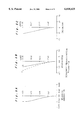
- FIG. 1 is a schematic view showing one embodiment of a wide-angle lens assembly according to the present invention
- FIG. 2 is an explanatory view showing an arrangement of wide-angle lens assemblies of the viewing angles of 70° to 90°;
- FIG. 3 is an explanatory view showing another arrangement of wide-angle lens assemblies of the viewing angle of 100° to 120°;
- FIG. 4a-4c are diagrams showing aberrations in the wide-angle lens assembly of the viewing angle of 70°;
- FIG. 5a-5c are diagrams showing aberrations in the wide-angle lens assembly of the viewing angle of 80°;
- FIG. 6a-6c are diagrams showing aberrations in the wide-angle lens assembly of the viewing angle of 90°;
- FIG. 7a-7c are diagrams showing aberrations in the wide-angle lens assembly of the viewing angle of 100°;
- FIG. 8a-8c are diagrams showing aberrations in the wide-angle lens assembly of the viewing angle of 110°.
- FIG. 9a-9c are diagrams showing aberrations in the wide-angle lens assembly of the viewing angle of 120°.
- a wide-angle lens assembly for a video camera will be described referring to FIGS. 1 to 9 and Tables 1 to 6.
- the wide-angle lens assembly of this embodiment is designed to have different viewing angles of 70°, 80°, 90°, 100°, 110°, and 120° as shown in FIG. 1.
- a lens 1 serves as a second lens which is commonly used in each arrangement of the different viewing angles.
- a lens 4 is commonly used as a first lens in each lens group of the viewing angles of 90°, 100°, 110°, and 120°.
- FIG. 2 shows the arrangement for each wide-angle lens assembly of the viewing angle of 70°, 80°, and 90°.
- the assembly comprises two groups of two lenses, including the first lens 2 (3,4) of a negative bi-concave lens having a convex side facing to an object side and the second lens 1 of a positive lens having a convex side facing to the object side.
- FIG. 3 shows the arrangement for each wide-angle lens assembly of the viewing angle of 100°, 110°, and 120°.
- the assembly comprises three groups of three lenses, including a zeroth lens 5 (6,7) of a negative meniscus lens, the first lens 4 of a negative bi-concove lens, and the second lens 1 of a positive lens, all having their convex sides facing to the object side.
- the reference numeral 8 denotes a flat parallel lens located on the back side of the last lens 1, since this embodiment is designed for use in a video camera.
- Exemplary values of optical parameters for each wide-angle lens assembly are shown in FIGS. 2 and 3 and Tables 1 to 6, in which f is a focal distance of each lens group and F represents an F number of the lens group.
- Ri is the curvature radius of a lens surface of an i-th lens from the object side
- Di is the distance between the surfaces of the i-th lens and of an (i+1)th lens
- Nj is the index of refraction of a j-th lens.
- the displacement X of the optical axis from the reference vertex point O of an aspherical lens is expressed by: ##EQU1## where K is a conical constant and A, B, and C are aspherical coefficients.
- FIGS. 4 to 9 show spherical aberration, astigmatism, and distortion in each different wide-angle lens assembly of the viewing angles from 70° to 120°.
- the reference numeral S and T represent a sagittal surface and a meridional surface, respectively.
- the horizontal viewing angle of the wide-angle lens assembly is arbitrarily determined within a range between the minimum and the maximum degree although its degrees in this embodiment are set at equal intervals of 10°.
- the wide-angle lens assembly of the present invention permits the second lens to be commonly used in all lens groups from the minimum to the maximum horizontal viewing angle and the first lens to be commonly used in the lens groups from the reference angle to the maximum horizontal viewing angle, thus reducing the overall number of lenses yet being able to correct aberrations through satisfying the required conditions.
Abstract
Description
              TABLE 1
______________________________________
f = 1.3082, F = 2.8,
Horizontal Viewing Angle = 70°, bf/f2 = 0.7852, f1/f2
______________________________________
= -1.4647
R1 = -17.10151 *1
               D1 =0.526200 N1 = 1.526400
R2 = 1.57860          D2 = 2.411752
R3 = 1.55668 *2
                   D3 =  1.512826
                                   N2 = 1.526400
R4 = -1.74523 *3
                   D4 = 0.438500
R5 = INFINITY            D5 = 0.350800
                                   N3 = 1.517120
R6 = INFINITY           D6 = 1.457646
______________________________________
 *1 Aspherical Surface K = 0.0, A = 0.154182E 02, B =  0.166538E 03, C =
 -0.256626E 04
 *2 Aspherical Surface K = 0.0, A = -0.379525E 01, B = -0.462606E 01, C =
 0.962347E 02
 *3 Aspherical Surface K = 0.0, A = 0.557427E 01, B = 0.185043E 01, C =
 0.320782E 01
              TABLE 2
______________________________________
f = 1.1398, F = 2.8,
Horizontal Viewing Angle = 80°, bf/f2 = 0.7233, f1/f2
______________________________________
= -1.4647
R1 = -17.10151 *1
               D1 =0.526200 N1 = 1.526400
R2 = 1.57860          D2 = 2.981802
R3 = 1.55668 *2
                   D3 =  1.512826
                                   N2 = 1.526400
R4 = -1.74523 *3
                   D4 = 0.438500
R5 = INFINITY            D5 = 0.350800
                                   N3 = 1.517120
R6 = INFINITY           D6 = 1.342667
______________________________________
 *1 Aspherical Surface K = 0.0, A = 0.3913852E 02, B =  0.616809E 04, C =
 -0.320782E 05
 *2 Aspherical Surface K = 0.0, A = -0.379525E 01, B = -0.462606E 01, C =
 0.962347E 02
 *3 Aspherical Surface K = 0.0, A = 0.557427E 01, B = 0.185043E 01, C =
 0.320782E 01
              TABLE 3
______________________________________
f = 1.0000, F = 2.8,
Horizontal Viewing Angle = 90°, bf/f2 = 0.6821, f1/f2
______________________________________
= -1.4248
    R1 = -13.15501 *1
                D1 =0.526200
                            N1 = 1.526400
R2 = 1.57860          D2 = 3.529928
R3 = 1.55668 *2
                   D3 =  1.512826
                                   N2 = 1.526400
R4 = -1.74523 *3
                   D4 = 0.438500
R5 = INFINITY            D5 = 0.350800
                                   N3 = 1.517120
R6 = INFINITY           D6 = 1.266319
______________________________________
 *1 Aspherical Surface K = 0.0, A = 0.699749E 02, B =  -0.191211E 03, C =
 -0.121897E 04
 *2 Aspherical Surface K = 0.0, A = -0.379525E 01, B = -0.462606E 01, C =
 0.962347E 02
 *3 Aspherical Surface K = 0.0, A = 0.557427E 01, B = 0.185043E 01, C =
 0.320782E 01
              TABLE 4
______________________________________
f = 0.9113, F = 2.8,
Horizontal Viewing Angle = 100°, bf/f2 = 0.7042, f0/f2
______________________________________
= -12.0122
    R1 = 10.08551
                   D1 =0.877001
                                  N1 = 1.526400
R2 = 5.26200          D2 = 1.315501
R3 = -13.15501 *1
                   D3 =  0.526200
                                   N2 = 1.526400
R4 = 1.57860       D4 = 3.529928
R5 = 1.55668             D5 = 1.512826
                                   N3 = 1.526400
R6 = -1.74523 *3
                        D6 = 0.438500
R7 = INFINITY  D7 = 0.350800
                            N4 = 1.517120
R8 = INFINITY  D8 = 1.266319
______________________________________
 *1 Aspherical Surface K = 0.0, A = 0.699749E 02, B =  -0.191211E 03, C =
 -0.121897E 04
 *2 Aspherical Surface K = 0.0, A = -0.379525E 01, B = -0.462606E 01, C =
 0.962347E 02
 *3 Aspherical Surface K = 0.0, A = 0.557427E 01, B = 0.185043E 01, C =
 0.320782E 01
              TABLE 5
______________________________________
f = 0.8518, F = 2.8,
Horizontal Viewing Angle = 110°, bf/f2 = 0.7132, f0/f2
______________________________________
= -7.9819
R1 = 17.10151  D1 =0.877001 N1 = 1.526400
R2 = 5.26200          D2 = 1.315501
R3 = -13.15501 *1
                   D3 =  0.526200
                                   N2 = 1.526400
R4 = 1.57860       D4 = 3.529928
R5 = 1.55668 *2
                         D5 = 1.512826
                                   N3 = 1.526400
R6 = -1.74523 *3
                        D6 = 0.438500
R7 = INFINITY  D7 = 0.350800
                            N4 = 1.517120
R8 = INFINITY  D8 = 1.266319
______________________________________
 *1 Aspherical Surface K = 0.0, A = 0.699749E 02, B =  -0.191211E 03, C =
 -0.121897E 04
 *2 Aspherical Surface K = 0.0, A = -0.379525E 01, B = -0.462606E 01, C =
 0.962347E 02
 *3 Aspherical Surface K = 0.0, A = 0.557427E 01, B = 0.185043E 01, C =
 0.320782E 01
              TABLE 6
______________________________________
f = 0.8151, F = 2.8,
Horizontal Viewing Angle = 120°, bf/f2 = 0.7186, f0/f2
______________________________________
= -6.4814
    R1 = 32.88752
               D1 =0.877001 N1 = 1.526400
R2 = 5.26200          D2 = 1.315501
R3 = -13.15501 *1
                   D3 =  0.526200
                                   N2 = 1.526400
R4 = 1.57860       D4 = 3.529928
R5 = 1.55668 *2
                         D5 = 1.512826
                                   N3 = 1.526400
R6 = -1.74523 *3
                        D6 = 0.438500
R7 = INFINITY  D7 = 0.350800
                            N4 = 1.517120
R8 = INFINITY  D8 = 1.266319
______________________________________
 *1 Aspherical Surface K = 0.0, A = 0.699749E 02, B =  -0.191211E 03, C =
 -0.121897E 04
 *2 Aspherical Surface K = 0.0, A = -0.379525E 01, B = -0.462606E 01, C =
 0.962347E 02
 *3 Aspherical Surface K = 0.0, A = 0.557427E 01, B = 0.185043E 01, C =
 0.320782E 01
Claims (3)
Applications Claiming Priority (2)
| Application Number | Priority Date | Filing Date | Title |
|---|---|---|---|
| JP8-259466 | 1996-09-30 | ||
| JP8259466A JPH10104509A (en) | 1996-09-30 | 1996-09-30 | Wide angle lens group |
Publications (1)
| Publication Number | Publication Date |
|---|---|
| US6018425A true US6018425A (en) | 2000-01-25 |
Family
ID=17334472
Family Applications (1)
| Application Number | Title | Priority Date | Filing Date |
|---|---|---|---|
| US08/939,230 Expired - Fee Related US6018425A (en) | 1996-09-30 | 1997-09-29 | Wide-angle lens assembly and method |
Country Status (2)
| Country | Link |
|---|---|
| US (1) | US6018425A (en) |
| JP (1) | JPH10104509A (en) |
Cited By (21)
| Publication number | Priority date | Publication date | Assignee | Title |
|---|---|---|---|---|
| US20030032356A1 (en) * | 1999-11-30 | 2003-02-13 | Matti Kiik | Roofing composite |
| US20040021956A1 (en) * | 1999-07-27 | 2004-02-05 | Donnelly Corporation, A Corporation Of The State Of Michigan | Wide angle imaging system |
| US20040032570A1 (en) * | 2002-08-16 | 2004-02-19 | Mark David Peterson | Rear projection display |
| US6757109B2 (en) * | 1999-07-27 | 2004-06-29 | Donnelly Corporation | Plastic lens system for vehicle imaging system |
| US20040155176A1 (en) * | 2003-02-05 | 2004-08-12 | Daisuke Ito | Lens system and image-taking apparatus having the same |
| US20040212881A1 (en) * | 2002-08-16 | 2004-10-28 | Mark Peterson | Laminate screen for display device |
| US20040218268A1 (en) * | 2002-08-16 | 2004-11-04 | Peterson Mark D. | Rear projection display |
| US20040223123A1 (en) * | 2002-08-16 | 2004-11-11 | Engle T. Scott | Projection device and screen |
| US20040227990A1 (en) * | 2002-08-16 | 2004-11-18 | Peterson Mark D. | Variable fresnel screen for use in projection device |
| US20040233394A1 (en) * | 2002-08-16 | 2004-11-25 | Gohman Jeffrey A. | Wide angle projection lens |
| US20040257539A1 (en) * | 2002-08-16 | 2004-12-23 | Peterson Mark D. | Projection television device and screen |
| US20050185270A1 (en) * | 2004-02-25 | 2005-08-25 | Scott Engle | Environmentally-adaptive frame assembly |
| US20060028623A1 (en) * | 2003-08-19 | 2006-02-09 | Engle Timothy S | Method and system for a thermal architecture and user adjustable keystone in a display device |
| US7009765B2 (en) | 2002-08-16 | 2006-03-07 | Infocus Corporation | Wide angle lens system having a distorted intermediate image |
| US7102820B2 (en) | 2002-08-16 | 2006-09-05 | Infocus Corporation | Flat valley fresnel lens for a display device |
| US7131001B1 (en) * | 1999-10-29 | 2006-10-31 | Broadcom Corporation | Apparatus and method for secure filed upgradability with hard wired public key |
| US20070014005A1 (en) * | 2002-08-16 | 2007-01-18 | Infocus Corporation | Laminate screen for a display device |
| US7259912B2 (en) | 2004-01-06 | 2007-08-21 | Infocus Corporation | Fresnel lens having reduced distortions |
| EP1879062A1 (en) * | 2006-07-13 | 2008-01-16 | Robert Bosch Gmbh | Rear view camera for a vehicle |
| CN101587231B (en) * | 2009-06-09 | 2011-02-02 | 宁波舜宇车载光学技术有限公司 | Megapixels large aperture vehicle front view lens |
| US10412298B2 (en) * | 2016-11-29 | 2019-09-10 | Guangdong Oppo Mobile Telecommunications Corp, Ltd. | Control method, control device and electronic device |
Families Citing this family (3)
| Publication number | Priority date | Publication date | Assignee | Title |
|---|---|---|---|---|
| JP4821121B2 (en) | 2005-01-31 | 2011-11-24 | コニカミノルタオプト株式会社 | Wide-angle lens system |
| JP4841928B2 (en) * | 2005-10-21 | 2011-12-21 | 富士フイルム株式会社 | Wide-angle imaging lens |
| JP4841929B2 (en) * | 2005-10-21 | 2011-12-21 | 富士フイルム株式会社 | Wide-angle imaging lens |
Citations (5)
| Publication number | Priority date | Publication date | Assignee | Title |
|---|---|---|---|---|
| US4413888A (en) * | 1981-01-13 | 1983-11-08 | Canon Kabushiki Kaisha | Compact photographic objective |
| US5268792A (en) * | 1991-05-20 | 1993-12-07 | Eastman Kodak Company | Zoom lens |
| US5473473A (en) * | 1993-12-20 | 1995-12-05 | Eastman Kodak Company | Two element plastic zoom camera lens |
| US5485313A (en) * | 1993-10-27 | 1996-01-16 | Polaroid Corporation | Zoom lens systems |
| US5646777A (en) * | 1992-04-16 | 1997-07-08 | Nikon Corporation | Keplerian zoom finder optical system |
-
1996
- 1996-09-30 JP JP8259466A patent/JPH10104509A/en active Pending
-
1997
- 1997-09-29 US US08/939,230 patent/US6018425A/en not_active Expired - Fee Related
Patent Citations (5)
| Publication number | Priority date | Publication date | Assignee | Title |
|---|---|---|---|---|
| US4413888A (en) * | 1981-01-13 | 1983-11-08 | Canon Kabushiki Kaisha | Compact photographic objective |
| US5268792A (en) * | 1991-05-20 | 1993-12-07 | Eastman Kodak Company | Zoom lens |
| US5646777A (en) * | 1992-04-16 | 1997-07-08 | Nikon Corporation | Keplerian zoom finder optical system |
| US5485313A (en) * | 1993-10-27 | 1996-01-16 | Polaroid Corporation | Zoom lens systems |
| US5473473A (en) * | 1993-12-20 | 1995-12-05 | Eastman Kodak Company | Two element plastic zoom camera lens |
Cited By (54)
| Publication number | Priority date | Publication date | Assignee | Title |
|---|---|---|---|---|
| US6922292B2 (en) | 1999-07-27 | 2005-07-26 | Donnelly Corporation | Wide angle imaging system |
| US20040021956A1 (en) * | 1999-07-27 | 2004-02-05 | Donnelly Corporation, A Corporation Of The State Of Michigan | Wide angle imaging system |
| US6757109B2 (en) * | 1999-07-27 | 2004-06-29 | Donnelly Corporation | Plastic lens system for vehicle imaging system |
| US7131001B1 (en) * | 1999-10-29 | 2006-10-31 | Broadcom Corporation | Apparatus and method for secure filed upgradability with hard wired public key |
| US20030032356A1 (en) * | 1999-11-30 | 2003-02-13 | Matti Kiik | Roofing composite |
| US7088507B2 (en) | 2002-08-16 | 2006-08-08 | Infocus Corporation | Rear projection display |
| US20080130106A1 (en) * | 2002-08-16 | 2008-06-05 | Infocus Corporation | Wide angle lens system having a distorted intermediate image |
| US20040212881A1 (en) * | 2002-08-16 | 2004-10-28 | Mark Peterson | Laminate screen for display device |
| US20040218268A1 (en) * | 2002-08-16 | 2004-11-04 | Peterson Mark D. | Rear projection display |
| US20040223123A1 (en) * | 2002-08-16 | 2004-11-11 | Engle T. Scott | Projection device and screen |
| US20040227990A1 (en) * | 2002-08-16 | 2004-11-18 | Peterson Mark D. | Variable fresnel screen for use in projection device |
| US20040032570A1 (en) * | 2002-08-16 | 2004-02-19 | Mark David Peterson | Rear projection display |
| US20040257539A1 (en) * | 2002-08-16 | 2004-12-23 | Peterson Mark D. | Projection television device and screen |
| US20050001990A1 (en) * | 2002-08-16 | 2005-01-06 | Peterson Mark David | Rear projection display device having multiple mirrors that are substantially parallel to a screen |
| US6896375B2 (en) | 2002-08-16 | 2005-05-24 | Infocus Corporation | Rear projection display device having multiple mirrors that are substantially parallel to a screen |
| US10955648B2 (en) | 2002-08-16 | 2021-03-23 | Seiko Epson Corporation | Projection television device and screen |
| US20060245055A1 (en) * | 2002-08-16 | 2006-11-02 | Infocus Corporation | Flat valley fresnel lens |
| US20050275811A1 (en) * | 2002-08-16 | 2005-12-15 | Peterson Mark D | Rear projection display device having multiple mirrors that are substantially parallel to a screen |
| US9733459B2 (en) | 2002-08-16 | 2017-08-15 | Seiko Epson Corporation | Projected television device and screen |
| US9429826B2 (en) | 2002-08-16 | 2016-08-30 | Seiko Epson Corporation | Projection television device and screen |
| US7009765B2 (en) | 2002-08-16 | 2006-03-07 | Infocus Corporation | Wide angle lens system having a distorted intermediate image |
| US9217912B2 (en) | 2002-08-16 | 2015-12-22 | Seiko Epson Corporation | Projection television device and screen |
| US8081377B2 (en) | 2002-08-16 | 2011-12-20 | Infocus Corporation | Wide angle lens system having a distorted intermediate image |
| US7777949B2 (en) | 2002-08-16 | 2010-08-17 | Seiko Epson Corporation | Laminate screen for a display device |
| US20090244701A1 (en) * | 2002-08-16 | 2009-10-01 | Infocus Corporation | Wide Angle Lens System Having a Distorted Intermediate Image |
| US7567380B2 (en) | 2002-08-16 | 2009-07-28 | Infocus Corporation | Rear projection display device having multiple mirrors that are substantially parallel to a screen |
| US20040047037A1 (en) * | 2002-08-16 | 2004-03-11 | Peterson Mark David | Rear projection display |
| US7090354B2 (en) | 2002-08-16 | 2006-08-15 | Infocus Corporation | Projection device and screen |
| US7102820B2 (en) | 2002-08-16 | 2006-09-05 | Infocus Corporation | Flat valley fresnel lens for a display device |
| US7088509B2 (en) | 2002-08-16 | 2006-08-08 | Infocus Corporation | Laminate screen for display device |
| US20040233394A1 (en) * | 2002-08-16 | 2004-11-25 | Gohman Jeffrey A. | Wide angle projection lens |
| US7545586B2 (en) | 2002-08-16 | 2009-06-09 | Infocus Corporation | Wide angle lens system having a distorted intermediate image |
| US7140735B2 (en) | 2002-08-16 | 2006-11-28 | Infocus Corporation | Rear projection display device having multiple mirrors that are substantially parallel to a screen |
| US7150537B2 (en) * | 2002-08-16 | 2006-12-19 | Infocus Corporation | Projection television device and screen |
| US6804055B2 (en) | 2002-08-16 | 2004-10-12 | Infocus Corporation | Fresnel lens for use with rear projection display |
| US20070014005A1 (en) * | 2002-08-16 | 2007-01-18 | Infocus Corporation | Laminate screen for a display device |
| US7175287B2 (en) | 2002-08-16 | 2007-02-13 | Infocus Corporation | Wide angle projection lens |
| US7253954B2 (en) | 2002-08-16 | 2007-08-07 | Infocus Corporation | Flat valley fresnel lens |
| US7341353B2 (en) | 2002-08-16 | 2008-03-11 | Infocus Corporation | Variable fresnel screen for use in projection device |
| US7161132B2 (en) | 2003-02-05 | 2007-01-09 | Canon Kabushiki Kaisha | Lens system and image-taking apparatus having the same |
| US20040155176A1 (en) * | 2003-02-05 | 2004-08-12 | Daisuke Ito | Lens system and image-taking apparatus having the same |
| US7041958B2 (en) * | 2003-02-05 | 2006-05-09 | Canon Kabushiki Kaisha | Lens system and image-taking apparatus having the same |
| US20060145061A1 (en) * | 2003-02-05 | 2006-07-06 | Daisuke Ito | Lens system and image-taking apparatus having the same |
| US20060203334A1 (en) * | 2003-08-19 | 2006-09-14 | Infocus Corporation | Method and system for a thermal architecture and user adjustable keystone in a display device |
| US7080910B2 (en) | 2003-08-19 | 2006-07-25 | Infocus Corporation | Method and system for a thermal architecture and user adjustable keystone in a display device |
| US20060028623A1 (en) * | 2003-08-19 | 2006-02-09 | Engle Timothy S | Method and system for a thermal architecture and user adjustable keystone in a display device |
| US7331678B2 (en) | 2003-08-19 | 2008-02-19 | Infocus Corporation | Method and system for a thermal architecture and user adjustable keystone in a display device |
| US7259912B2 (en) | 2004-01-06 | 2007-08-21 | Infocus Corporation | Fresnel lens having reduced distortions |
| WO2005067621A3 (en) * | 2004-01-06 | 2006-03-02 | Infocus Corp | Projection televison device and screen |
| US20050185270A1 (en) * | 2004-02-25 | 2005-08-25 | Scott Engle | Environmentally-adaptive frame assembly |
| US7050228B2 (en) | 2004-02-25 | 2006-05-23 | Infocus Corporation | Environmentally-adaptive frame assembly |
| EP1879062A1 (en) * | 2006-07-13 | 2008-01-16 | Robert Bosch Gmbh | Rear view camera for a vehicle |
| CN101587231B (en) * | 2009-06-09 | 2011-02-02 | 宁波舜宇车载光学技术有限公司 | Megapixels large aperture vehicle front view lens |
| US10412298B2 (en) * | 2016-11-29 | 2019-09-10 | Guangdong Oppo Mobile Telecommunications Corp, Ltd. | Control method, control device and electronic device |
Also Published As
| Publication number | Publication date |
|---|---|
| JPH10104509A (en) | 1998-04-24 |
Similar Documents
| Publication | Publication Date | Title |
|---|---|---|
| US6018425A (en) | Wide-angle lens assembly and method | |
| US6185048B1 (en) | Zoom lens system | |
| US7075734B2 (en) | Zoom lens system | |
| US6016228A (en) | Zoom lens system | |
| US5162945A (en) | Ocular lens system | |
| US6940655B2 (en) | Super wide-angle zoom lens system | |
| JP2599312B2 (en) | Super wide angle lens | |
| EP3242151A1 (en) | Retrofocus lens system and image-taking device | |
| EP1970742A2 (en) | Close-up lens, imaging apparatus , and method for focusing close-up lens | |
| JPS6352364B2 (en) | ||
| JPS61213817A (en) | Zoom finder | |
| US4139265A (en) | Modified gauss type photographic lens | |
| JPS6132653B2 (en) | ||
| JPH04246606A (en) | Super wide angle lens | |
| JPH04238312A (en) | Subminiature extremely wide-angle lens | |
| JPH085908A (en) | Wide-angle lens | |
| US6809878B2 (en) | Zoom lens | |
| JPH10333037A (en) | Zoom lens | |
| US6181484B1 (en) | Compact two-group wide-angle zoom lens | |
| JPH07104183A (en) | Bright triplet lens | |
| JP2924153B2 (en) | Compact zoom lens | |
| US4550987A (en) | Small size telephoto lens | |
| JPH1096858A (en) | Zoom lens | |
| JP3448403B2 (en) | Zoom lens | |
| US5414560A (en) | Single lens |
Legal Events
| Date | Code | Title | Description |
|---|---|---|---|
| AS | Assignment |
Owner name: MATSUSHITA ELECTRIC INDUSTRIAL CO., LTD., JAPAN Free format text: ASSIGNMENT OF ASSIGNORS INTEREST;ASSIGNORS:NAKABQYASHI, KOKI;UENO, KAZUO;MOCHIDA, SHORO;REEL/FRAME:008833/0565 Effective date: 19970722 |
|
| AS | Assignment |
Owner name: MATSUSHITA ELECTRIC INDUSTRIAL CO., LTD., JAPAN Free format text: ASSIGNMENT OF ASSIGNORS INTEREST;ASSIGNORS:NAKABAYASHI, KOKI;UENO, KAZUO;MOCHIDA, SHORO;REEL/FRAME:009010/0618 Effective date: 19970722 |
|
| CC | Certificate of correction | ||
| FPAY | Fee payment |
Year of fee payment: 4 |
|
| FEPP | Fee payment procedure |
Free format text: PAYOR NUMBER ASSIGNED (ORIGINAL EVENT CODE: ASPN); ENTITY STATUS OF PATENT OWNER: LARGE ENTITY |
|
| REMI | Maintenance fee reminder mailed | ||
| LAPS | Lapse for failure to pay maintenance fees | ||
| STCH | Information on status: patent discontinuation |
Free format text: PATENT EXPIRED DUE TO NONPAYMENT OF MAINTENANCE FEES UNDER 37 CFR 1.362 |
|
| FP | Lapsed due to failure to pay maintenance fee |
Effective date: 20080125 |