US6032608A - Pointer indicator - Google Patents
Pointer indicator Download PDFInfo
- Publication number
- US6032608A US6032608A US09/011,926 US1192698A US6032608A US 6032608 A US6032608 A US 6032608A US 1192698 A US1192698 A US 1192698A US 6032608 A US6032608 A US 6032608A
- Authority
- US
- United States
- Prior art keywords
- pointer
- light
- illuminated
- reflective surface
- axial section
- Prior art date
- Legal status (The legal status is an assumption and is not a legal conclusion. Google has not performed a legal analysis and makes no representation as to the accuracy of the status listed.)
- Expired - Fee Related
Links
Images
Classifications
-
- G—PHYSICS
- G01—MEASURING; TESTING
- G01D—MEASURING NOT SPECIALLY ADAPTED FOR A SPECIFIC VARIABLE; ARRANGEMENTS FOR MEASURING TWO OR MORE VARIABLES NOT COVERED IN A SINGLE OTHER SUBCLASS; TARIFF METERING APPARATUS; MEASURING OR TESTING NOT OTHERWISE PROVIDED FOR
- G01D13/00—Component parts of indicators for measuring arrangements not specially adapted for a specific variable
- G01D13/22—Pointers, e.g. settable pointer
- G01D13/28—Pointers, e.g. settable pointer with luminescent markings
-
- G—PHYSICS
- G01—MEASURING; TESTING
- G01D—MEASURING NOT SPECIALLY ADAPTED FOR A SPECIFIC VARIABLE; ARRANGEMENTS FOR MEASURING TWO OR MORE VARIABLES NOT COVERED IN A SINGLE OTHER SUBCLASS; TARIFF METERING APPARATUS; MEASURING OR TESTING NOT OTHERWISE PROVIDED FOR
- G01D11/00—Component parts of measuring arrangements not specially adapted for a specific variable
- G01D11/28—Structurally-combined illuminating devices
-
- G—PHYSICS
- G12—INSTRUMENT DETAILS
- G12B—CONSTRUCTIONAL DETAILS OF INSTRUMENTS, OR COMPARABLE DETAILS OF OTHER APPARATUS, NOT OTHERWISE PROVIDED FOR
- G12B11/00—Indicating elements; Illumination thereof
- G12B11/04—Pointers; Setting-mechanisms therefor
Definitions
- a pointer device is described in German Patent No. DE 33 47 014 C2.
- This pointer device has a pointer, mounted rotatably about a pointer axis, which is made of transparent light-guiding material.
- Permanently mounted on the side of the pointer facing away from the observer is a light source whose light is coupled, axially with respect to the pointer axis, into the light-guiding material of the illuminated pointer.
- the light coupled in axially in this fashion can be deflected via a light-guiding insert into the radial longitudinal extension direction of the pointer.
- the pointer device has, as compared with the existing art, the advantage that the illumination density of a passive illuminated pointer is considerably increased. This offers the advantage, in cases in which very good illumination of the pointer is necessary, of also being able to use a passive illuminated pointer, and not utilizing a considerably more expensive active illuminated pointer.
- the arrangement combines the practically loss-free total reflection of rays which strike at a large angle to the perpendicular to the surface with the additional reflection of rays which strike at a small angle to the perpendicular to the surface.
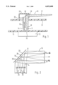
- FIG. 1 shows an exemplary embodiment of the pointer device according to the present invention.
- FIG. 2 shows the beam path of the light in the exemplary embodiment depicted in FIG. 1.
- FIG. 1 shows a pointer arrangement with a passive illuminated pointer.
- the light source is not integrated into the pointer itself, but rather the light is coupled into the rotatably mounted illuminated pointer from a permanently mounted light source.
- multiple LEDs 12 are mounted on a circuit board 11, only one individual LED being depicted here for the sake of simplicity. These multiple LEDs 12 are preferably mounted and contacted on the circuit board with a spacing of approximately 60 degrees.
- a meter mechanism 13 Located on the side of the circuit board facing away from the observer is a meter mechanism 13 which drives a pointer shaft 14 which passes through an opening in circuit board 11.
- Illuminated pointer 16 is attached with its pointer hub 15 onto pointer shaft 14.
- the pointer hub 15 and illuminated pointer 16 are shaped integrally from a light guide.
- Illuminated pointer 16 itself includes a radial section enclosing a right angle, which represents pointer vane 17, and an axial section which constitutes a light gatherer 18.
- light from LEDs 12 is coupled axially into light gatherer 18 and then deflected at reflective surface 19, by total reflection, into the radial pointer vane 17.
- a first-surface mirror 20 is provided parallel to reflective surface 19 at a small spacing from reflective surface 19.
- dial face 21 Located on the side of illuminated pointer 16 facing away from the observer is dial face 21, which has an opening 22 through which pointer hub 15 and light gatherer 18 pass. Opening 22 in dial face 21, the pointer hub, and the light gatherer are covered by a cap 23.
- the cap 23 is white in color on the inside so that light emerging from pointer 16 is reflected back into the pointer.
- FIG. 2 The beam path for light deflection out of the axial part of illuminated pointer 16 into the radial part of illuminated pointer 16 is depicted in FIG. 2. Identical parts here are given identical reference characters.
- the schematic path of light propagation in the light-guiding material of illuminated pointer 16 is indicated with arrows 24.
- the light emerges from LED 12 (not depicted), and is coupled into the axial light gatherer 18.
- accessory mirror 20 is also provided.
- Accessory mirror is provided because a portion of the light rays of the LED can emerge from the light-guiding material because of the angle of incidence upon reflective surface 19.
- Light rays 25 emerging from the light-guiding material are reflected from first-surface mirror 20 back into the light guide, and thus into the radial pointer vane of illuminated pointer 16. With this arrangement it is possible for the light rays which are coupled, substantially by total reflection, into pointer vane 17 because of their large angle of incidence with respect to the perpendicular to reflective surface 19 to be reinforced.
- First-surface mirror 20 can, for example, be punched out of a vacuum-metallized plastic film (polycarbonate), and initially placed in a protrusion, provided for the purpose, of cap 23, and thus initially immobilized. It is then finally retained with the insertion of the light guide.
- a vacuum-metallized plastic film polycarbonate
Abstract
Description
Claims (3)
Applications Claiming Priority (3)
| Application Number | Priority Date | Filing Date | Title |
|---|---|---|---|
| DE19624081A DE19624081A1 (en) | 1996-06-17 | 1996-06-17 | Pointer device |
| DE19624081 | 1996-06-17 | ||
| PCT/DE1997/000935 WO1997049090A1 (en) | 1996-06-17 | 1997-05-09 | Pointer indicator |
Publications (1)
| Publication Number | Publication Date |
|---|---|
| US6032608A true US6032608A (en) | 2000-03-07 |
Family
ID=7797144
Family Applications (1)
| Application Number | Title | Priority Date | Filing Date |
|---|---|---|---|
| US09/011,926 Expired - Fee Related US6032608A (en) | 1996-06-17 | 1997-05-09 | Pointer indicator |
Country Status (5)
| Country | Link |
|---|---|
| US (1) | US6032608A (en) |
| EP (1) | EP0845145B1 (en) |
| JP (1) | JPH11510913A (en) |
| DE (2) | DE19624081A1 (en) |
| WO (1) | WO1997049090A1 (en) |
Cited By (17)
| Publication number | Priority date | Publication date | Assignee | Title |
|---|---|---|---|---|
| US20030189819A1 (en) * | 2002-04-05 | 2003-10-09 | Yazaki Corporation | Pointer type indicator |
| US6854416B2 (en) * | 2000-12-21 | 2005-02-15 | Siemens Aktiengesellschaft | Display instrument |
| US20060039130A1 (en) * | 2004-08-18 | 2006-02-23 | Yazaki Corporation | Pointer |
| US20060285308A1 (en) * | 2005-06-20 | 2006-12-21 | Siemens Vdo Automotive Corporation | High light-efficiency illumination cluster |
| US20080105191A1 (en) * | 2006-11-07 | 2008-05-08 | Denso International America, Inc. | Gauge pointer and light guide structure |
| WO2008076057A1 (en) * | 2006-12-21 | 2008-06-26 | Scania Cv Ab (Publ) | An instrument cluster for a motor vehicle and a motor vehicle comprising an instrument cluster |
| US20080264328A1 (en) * | 2007-04-27 | 2008-10-30 | Birman Vyacheslav B | Illuminated hub pointer |
| US20080310141A1 (en) * | 2007-06-12 | 2008-12-18 | Samir Mezouari | Vehicle instrument cluster |
| US20090038535A1 (en) * | 2007-08-07 | 2009-02-12 | Jorge Morales | Instrument Pointer Assembly |
| US20100064962A1 (en) * | 2008-09-17 | 2010-03-18 | Birman Vyacheslav B | Flood illuminated cluster with telltales |
| US20100188835A1 (en) * | 2009-01-27 | 2010-07-29 | Denso International America, Inc. | Illuminated indicating devices for instrument panels |
| US20100186661A1 (en) * | 2009-01-27 | 2010-07-29 | Denso International America, Inc. | Hub glow pointer |
| US20110182052A1 (en) * | 2010-01-25 | 2011-07-28 | Johnson Controls Technology Company | Pointer structure of an instrument cluster |
| CN102522125A (en) * | 2011-11-04 | 2012-06-27 | 埃泰克汽车电子(芜湖)有限公司 | Combination instrument assembly for car |
| US20120247385A1 (en) * | 2011-03-31 | 2012-10-04 | Denso Corporation | Backlit reflective pointer |
| US20180364078A1 (en) * | 2016-02-26 | 2018-12-20 | Continental Automotive Systems, Inc. | Front pick-up illuminated pointer |
| US11009652B2 (en) * | 2018-10-09 | 2021-05-18 | The Swatch Group Research And Development Ltd | Luminous display device |
Families Citing this family (5)
| Publication number | Priority date | Publication date | Assignee | Title |
|---|---|---|---|---|
| DE19828041A1 (en) | 1998-06-24 | 2000-01-05 | Mannesmann Vdo Ag | Pointer instrument |
| IT1303569B1 (en) * | 1998-09-01 | 2000-11-14 | Magneti Marelli Spa | BACKLIT MONOBLOCK INDEX GROUP. |
| DE19956542A1 (en) * | 1999-11-24 | 2001-05-31 | Mannesmann Vdo Ag | Display instrument for vehicle with LED and light conductive indicator fixedly connected to indicator shaft formed as light conductor |
| DE10225946A1 (en) * | 2002-06-11 | 2003-12-24 | Borg Instr Ag | Pointer with hollow shaft |
| DE102007001737B4 (en) * | 2007-01-11 | 2012-10-11 | Audi Ag | Pointer arrangement for a pointer instrument |
Citations (17)
| Publication number | Priority date | Publication date | Assignee | Title |
|---|---|---|---|---|
| US2902970A (en) * | 1957-10-09 | 1959-09-08 | Avien Inc | Illuminated dial pointer |
| US4218726A (en) * | 1977-11-09 | 1980-08-19 | Nissan Motor Company, Limited | Indicator gauge with illuminated pointer |
| US4274358A (en) * | 1978-06-26 | 1981-06-23 | Nissan Motor Company, Limited | Illuminated indicator gauge |
| US4339400A (en) * | 1981-05-11 | 1982-07-13 | Sorko Ram Paul A | Process for producing three-dimensional, mirrored acrylic articles |
| DE3201571A1 (en) * | 1982-01-20 | 1983-07-28 | Vdo Adolf Schindling Ag, 6000 Frankfurt | Display device |
| DE3347014A1 (en) * | 1983-12-24 | 1985-07-04 | Vdo Schindling | Pointer device |
| US4872415A (en) * | 1987-01-23 | 1989-10-10 | Nissan Motor Company, Limited | Meter for a vehicle |
| US4959759A (en) * | 1989-08-04 | 1990-09-25 | Delco Electronics Corporation | Automotive instrument display having a thickfilm electroluminescent lightpipe pointer |
| JPH03259714A (en) * | 1990-03-09 | 1991-11-19 | Nippondenso Co Ltd | Pointer lighting device for instrument |
| FR2672676A1 (en) * | 1991-02-13 | 1992-08-14 | Jaeger | IMPROVED LIGHTING NEEDLE. |
| US5199376A (en) * | 1989-07-29 | 1993-04-06 | Combined Optical Industries Limited | Pointers |
| US5291851A (en) * | 1990-06-29 | 1994-03-08 | Yazaki Corporation | Gauge for automobile |
| FR2710978A1 (en) * | 1993-10-08 | 1995-04-14 | Jaeger | Indicator assembly with needle, needle therefor and application to motor vehicle dashboards |
| US5458082A (en) * | 1994-03-24 | 1995-10-17 | Delco Electronics Corp. | Tip to tail illuminated pointer |
| JPH08193852A (en) * | 1995-09-08 | 1996-07-30 | Kansei Corp | Indicating instrument |
| US5546888A (en) * | 1994-09-09 | 1996-08-20 | Delco Electronics Corporation | Surface mounted gauge with illuminated pointer |
| US5690049A (en) * | 1996-02-05 | 1997-11-25 | Ford Motor Company | Compact gauge assembly |
Family Cites Families (4)
| Publication number | Priority date | Publication date | Assignee | Title |
|---|---|---|---|---|
| DE3300270A1 (en) * | 1983-01-07 | 1984-07-12 | Vdo Adolf Schindling Ag, 6000 Frankfurt | Indicator |
| DE3425029A1 (en) * | 1983-07-08 | 1985-01-31 | Yazaki Corp., Tokio/Tokyo | Illuminating device in a measuring instrument |
| FR2615992B1 (en) * | 1987-05-25 | 1989-09-22 | Jaeger | LIGHTING NEEDLE, PARTICULARLY FOR DASHBOARDS OF MOTOR VEHICLES |
| DE3824391A1 (en) * | 1988-07-19 | 1990-01-25 | Vdo Schindling | Indicating instrument |
-
1996
- 1996-06-17 DE DE19624081A patent/DE19624081A1/en not_active Ceased
-
1997
- 1997-05-09 JP JP10502044A patent/JPH11510913A/en active Pending
- 1997-05-09 WO PCT/DE1997/000935 patent/WO1997049090A1/en active IP Right Grant
- 1997-05-09 US US09/011,926 patent/US6032608A/en not_active Expired - Fee Related
- 1997-05-09 EP EP97922898A patent/EP0845145B1/en not_active Expired - Lifetime
- 1997-05-09 DE DE1997512010 patent/DE59712010D1/en not_active Expired - Lifetime
Patent Citations (17)
| Publication number | Priority date | Publication date | Assignee | Title |
|---|---|---|---|---|
| US2902970A (en) * | 1957-10-09 | 1959-09-08 | Avien Inc | Illuminated dial pointer |
| US4218726A (en) * | 1977-11-09 | 1980-08-19 | Nissan Motor Company, Limited | Indicator gauge with illuminated pointer |
| US4274358A (en) * | 1978-06-26 | 1981-06-23 | Nissan Motor Company, Limited | Illuminated indicator gauge |
| US4339400A (en) * | 1981-05-11 | 1982-07-13 | Sorko Ram Paul A | Process for producing three-dimensional, mirrored acrylic articles |
| DE3201571A1 (en) * | 1982-01-20 | 1983-07-28 | Vdo Adolf Schindling Ag, 6000 Frankfurt | Display device |
| DE3347014A1 (en) * | 1983-12-24 | 1985-07-04 | Vdo Schindling | Pointer device |
| US4872415A (en) * | 1987-01-23 | 1989-10-10 | Nissan Motor Company, Limited | Meter for a vehicle |
| US5199376A (en) * | 1989-07-29 | 1993-04-06 | Combined Optical Industries Limited | Pointers |
| US4959759A (en) * | 1989-08-04 | 1990-09-25 | Delco Electronics Corporation | Automotive instrument display having a thickfilm electroluminescent lightpipe pointer |
| JPH03259714A (en) * | 1990-03-09 | 1991-11-19 | Nippondenso Co Ltd | Pointer lighting device for instrument |
| US5291851A (en) * | 1990-06-29 | 1994-03-08 | Yazaki Corporation | Gauge for automobile |
| FR2672676A1 (en) * | 1991-02-13 | 1992-08-14 | Jaeger | IMPROVED LIGHTING NEEDLE. |
| FR2710978A1 (en) * | 1993-10-08 | 1995-04-14 | Jaeger | Indicator assembly with needle, needle therefor and application to motor vehicle dashboards |
| US5458082A (en) * | 1994-03-24 | 1995-10-17 | Delco Electronics Corp. | Tip to tail illuminated pointer |
| US5546888A (en) * | 1994-09-09 | 1996-08-20 | Delco Electronics Corporation | Surface mounted gauge with illuminated pointer |
| JPH08193852A (en) * | 1995-09-08 | 1996-07-30 | Kansei Corp | Indicating instrument |
| US5690049A (en) * | 1996-02-05 | 1997-11-25 | Ford Motor Company | Compact gauge assembly |
Cited By (29)
| Publication number | Priority date | Publication date | Assignee | Title |
|---|---|---|---|---|
| US6854416B2 (en) * | 2000-12-21 | 2005-02-15 | Siemens Aktiengesellschaft | Display instrument |
| US20030189819A1 (en) * | 2002-04-05 | 2003-10-09 | Yazaki Corporation | Pointer type indicator |
| US6863411B2 (en) * | 2002-04-05 | 2005-03-08 | Yazaki Corporation | Pointer type indicator having means to improve dial visibility |
| US20060039130A1 (en) * | 2004-08-18 | 2006-02-23 | Yazaki Corporation | Pointer |
| US7635192B2 (en) * | 2004-08-18 | 2009-12-22 | Yazaki Corporation | Pointer having a curved Reflective Surface |
| US7458695B2 (en) * | 2005-06-20 | 2008-12-02 | Continental Automotive Systems Us, Inc. | High light-efficiency illumination cluster |
| US20060285308A1 (en) * | 2005-06-20 | 2006-12-21 | Siemens Vdo Automotive Corporation | High light-efficiency illumination cluster |
| US7404374B2 (en) | 2006-11-07 | 2008-07-29 | Denso International America, Inc. | Gauge pointer and light guide structure |
| US20080105191A1 (en) * | 2006-11-07 | 2008-05-08 | Denso International America, Inc. | Gauge pointer and light guide structure |
| WO2008076057A1 (en) * | 2006-12-21 | 2008-06-26 | Scania Cv Ab (Publ) | An instrument cluster for a motor vehicle and a motor vehicle comprising an instrument cluster |
| US20080264328A1 (en) * | 2007-04-27 | 2008-10-30 | Birman Vyacheslav B | Illuminated hub pointer |
| US7665413B2 (en) * | 2007-04-27 | 2010-02-23 | Continental Automotive Systems Us, Inc. | Illuminated hub pointer |
| US20080310141A1 (en) * | 2007-06-12 | 2008-12-18 | Samir Mezouari | Vehicle instrument cluster |
| US20090038535A1 (en) * | 2007-08-07 | 2009-02-12 | Jorge Morales | Instrument Pointer Assembly |
| US20100064962A1 (en) * | 2008-09-17 | 2010-03-18 | Birman Vyacheslav B | Flood illuminated cluster with telltales |
| US8261686B2 (en) * | 2008-09-17 | 2012-09-11 | Continental Automotive Systems Us, Inc. | Flood illuminated cluster with telltales |
| US8225736B2 (en) * | 2009-01-27 | 2012-07-24 | Denso International America, Inc. | Hub glow pointer |
| US20100186661A1 (en) * | 2009-01-27 | 2010-07-29 | Denso International America, Inc. | Hub glow pointer |
| US20100188835A1 (en) * | 2009-01-27 | 2010-07-29 | Denso International America, Inc. | Illuminated indicating devices for instrument panels |
| US8016442B2 (en) * | 2009-01-27 | 2011-09-13 | Denso International America, Inc. | Illuminated indicating devices for instrument panels |
| CN102145667A (en) * | 2010-01-25 | 2011-08-10 | 约翰逊控制技术公司 | Pointer structure of an instrument cluster |
| US20110182052A1 (en) * | 2010-01-25 | 2011-07-28 | Johnson Controls Technology Company | Pointer structure of an instrument cluster |
| US8579448B2 (en) * | 2010-01-25 | 2013-11-12 | Johnson Controls Technology Company | Pointer structure of an instrument cluster |
| US20120247385A1 (en) * | 2011-03-31 | 2012-10-04 | Denso Corporation | Backlit reflective pointer |
| US8935989B2 (en) * | 2011-03-31 | 2015-01-20 | Denso International America, Inc. | Backlit reflective pointer |
| CN102522125A (en) * | 2011-11-04 | 2012-06-27 | 埃泰克汽车电子(芜湖)有限公司 | Combination instrument assembly for car |
| US20180364078A1 (en) * | 2016-02-26 | 2018-12-20 | Continental Automotive Systems, Inc. | Front pick-up illuminated pointer |
| US11035701B2 (en) * | 2016-02-26 | 2021-06-15 | Continental Automotive Systems, Inc. | Front pick-up illuminated pointer |
| US11009652B2 (en) * | 2018-10-09 | 2021-05-18 | The Swatch Group Research And Development Ltd | Luminous display device |
Also Published As
| Publication number | Publication date |
|---|---|
| JPH11510913A (en) | 1999-09-21 |
| EP0845145B1 (en) | 2004-10-13 |
| WO1997049090A1 (en) | 1997-12-24 |
| DE19624081A1 (en) | 1997-12-18 |
| DE59712010D1 (en) | 2004-11-18 |
| EP0845145A1 (en) | 1998-06-03 |
Similar Documents
| Publication | Publication Date | Title |
|---|---|---|
| US6032608A (en) | Pointer indicator | |
| EP1877736B1 (en) | Gauge with illuminated dial and pointer | |
| JP3426226B1 (en) | Light guide member, lighting unit and instrument | |
| KR960035391A (en) | Display panel for on board equipment | |
| KR20200071022A (en) | Vehicle light and/or signalling device | |
| KR100378649B1 (en) | Illumination structure of meter for vehicle instrumental panel | |
| US4872415A (en) | Meter for a vehicle | |
| US6663251B2 (en) | Gauge with illuminated dial and pointer | |
| US20050162843A1 (en) | Tip to tail to center pointer | |
| JP3803062B2 (en) | Vehicle indicating device | |
| JPH0921655A (en) | Equipment panel indicator | |
| JP5060840B2 (en) | Luminous pointer instrument | |
| JP3818229B2 (en) | Indicator lighting structure | |
| EP3825602B1 (en) | Automotive lighting and/or signaling device | |
| JPH10132618A (en) | Pointer illuminating device | |
| JP3052868B2 (en) | Instrument lighting device | |
| JP3401787B2 (en) | Pointer lighting device | |
| JP2004233241A (en) | Lighting device for measuring instrument | |
| JPH0566519U (en) | Instrument lighting equipment | |
| JP2001272478A (en) | Pointer type clock | |
| JP5884686B2 (en) | Luminous pointer instrument | |
| JPH1019610A (en) | Lighting system for instrument | |
| JP2004184335A (en) | Display apparatus | |
| JP2885196B2 (en) | Light emission guide | |
| JP2001153688A (en) | Instrument device |
Legal Events
| Date | Code | Title | Description |
|---|---|---|---|
| AS | Assignment |
Owner name: ROBERT BOSCH GMBH, GERMANY Free format text: ASSIGNMENT OF ASSIGNORS INTEREST;ASSIGNORS:OREANS, DERK;HERZOG, BERNHARD;REEL/FRAME:009071/0792;SIGNING DATES FROM 19980108 TO 19980117 |
|
| FEPP | Fee payment procedure |
Free format text: PAYOR NUMBER ASSIGNED (ORIGINAL EVENT CODE: ASPN); ENTITY STATUS OF PATENT OWNER: LARGE ENTITY |
|
| FPAY | Fee payment |
Year of fee payment: 4 |
|
| FPAY | Fee payment |
Year of fee payment: 8 |
|
| REMI | Maintenance fee reminder mailed | ||
| LAPS | Lapse for failure to pay maintenance fees | ||
| STCH | Information on status: patent discontinuation |
Free format text: PATENT EXPIRED DUE TO NONPAYMENT OF MAINTENANCE FEES UNDER 37 CFR 1.362 |
|
| FP | Lapsed due to failure to pay maintenance fee |
Effective date: 20120307 |