US6032691A - Valve assembly - Google Patents
Valve assembly Download PDFInfo
- Publication number
- US6032691A US6032691A US09/280,095 US28009599A US6032691A US 6032691 A US6032691 A US 6032691A US 28009599 A US28009599 A US 28009599A US 6032691 A US6032691 A US 6032691A
- Authority
- US
- United States
- Prior art keywords
- bore
- valve
- port
- inlet
- outlet
- Prior art date
- Legal status (The legal status is an assumption and is not a legal conclusion. Google has not performed a legal analysis and makes no representation as to the accuracy of the status listed.)
- Expired - Fee Related
Links
Images
Classifications
-
- F—MECHANICAL ENGINEERING; LIGHTING; HEATING; WEAPONS; BLASTING
- F16—ENGINEERING ELEMENTS AND UNITS; GENERAL MEASURES FOR PRODUCING AND MAINTAINING EFFECTIVE FUNCTIONING OF MACHINES OR INSTALLATIONS; THERMAL INSULATION IN GENERAL
- F16L—PIPES; JOINTS OR FITTINGS FOR PIPES; SUPPORTS FOR PIPES, CABLES OR PROTECTIVE TUBING; MEANS FOR THERMAL INSULATION IN GENERAL
- F16L29/00—Joints with fluid cut-off means
- F16L29/04—Joints with fluid cut-off means with a cut-off device in each of the two pipe ends, the cut-off devices being automatically opened when the coupling is applied
-
- Y—GENERAL TAGGING OF NEW TECHNOLOGICAL DEVELOPMENTS; GENERAL TAGGING OF CROSS-SECTIONAL TECHNOLOGIES SPANNING OVER SEVERAL SECTIONS OF THE IPC; TECHNICAL SUBJECTS COVERED BY FORMER USPC CROSS-REFERENCE ART COLLECTIONS [XRACs] AND DIGESTS
- Y10—TECHNICAL SUBJECTS COVERED BY FORMER USPC
- Y10T—TECHNICAL SUBJECTS COVERED BY FORMER US CLASSIFICATION
- Y10T137/00—Fluid handling
- Y10T137/8593—Systems
- Y10T137/87917—Flow path with serial valves and/or closures
- Y10T137/87925—Separable flow path section, valve or closure in each
- Y10T137/87941—Each valve and/or closure operated by coupling motion
- Y10T137/87949—Linear motion of flow path sections operates both
- Y10T137/87957—Valves actuate each other
Definitions
- This invention relates to a valve assembly for filling gas cylinders, more particularly a valve assembly that reduces the amount of gas wasted during the filling process.
- the design of the present valve assembly of this invention reduces chemical loss at the cylinder connections by sealing both the cylinder and the manifold from the environment when the cylinders are connected to and disconnected from the manifold. Thus, the chemical loss is decreased and safety of the operators in increased.
- a valve assembly may be used in connection with a tank filling apparatus, or in connection with other apparatus or methods.
- the valve assembly comprises an inlet valve connectable to an outlet valve having a first end adapted to engage a receptacle for holding process material and configured to have an inlet port; a second end adapted to engage said second end of an outlet valve and configured to have an outlet port; a bore extending between the inlet and outlet ports; and, a first plug movably positioned in the bore, having an open and a closed position, and sealing the inlet port from the outlet port when in the closed position.
- the valve assembly further comprises an outlet valve having a first end adapted to engage a source of process material and configured to have an inlet port; a second end adapted to engage the inlet valve and configured to have an outlet port; a bore extending between the inlet and outlet ports; and, a second plug movably positioned in the bore, having an open and a closed position, and sealing the inlet port from the outlet port when in the closed position.
- the valve assembly also comprises a transfer tube having a first end configured to be insertable into the inlet valve bore and configured to have at least one port; a second end configured to be insertable into the outlet valve bore and configured to have at least one port; and, a bore extending through the transfer tube, allowing fluid communication between the ports.
- the valve assembly may further comprise inserts positionable within the bores of the inlet or outlet valves.
- the inserts have bores extending therethrough to allow fluid communication between the ends thereof which are configured with one or more ports.
- the ends of the transfer tube are configured to be insertable into the bores of the inserts.
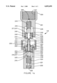
- FIG. 1a illustrates a cross-sectional view of a preferred embodiment of a valve used with the invention to connect the manifold to a cylinder.
- FIG. 1b illustrates the transfer tube used to transport process material between the valve bodies of the valve assembly that operatively connects the manifold to the cylinders.
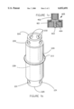
- FIG. 1c illustrates a fitting used to transfer process material from a cylinder having an inlet valve attached thereto.
- valve assembly 116 comprises an inlet valve 201 connectable to an outlet valve 202.
- Valves 201, 202 may be connected directly to each other using threaded or other connections, such as a coupler 203.
- Coupler 203 is rotatably mounted to outlet valve 202 using a shoulder and snap ring assembly, or any other suitable assembly for connecting coupler 203 to outlet valve 202.
- Each valve 201, 202 is constructed similar to a spring-loaded ball or plug check valve having a plug or ball positioned within the bores 235, 236 of respective valves 201, 202.
- Inlet valve 201 is configured with inlet port 206 and an outlet port 222 with bore 235 extending therebetween.
- First end 204 of inlet valve 201 is configured with threads 207 that mate with opposing threads on cylinder 117 or other receptacle for holding a process material.
- Threads 211 Positioned on the outer surface of inlet valve 201 at second end 234 are threads 211 that mate with corresponding threads 212 on coupler 203 or other connection member on outlet valve 202.
- first spring 215 Positioned within bore 235 is first spring 215 operatively positioned or mounted therein so that first plug 216 seals against seat 217 when at rest, thereby sealing inlet port 206 from outlet port 222.
- Seats 217 may be constructed from suitable o-rings.
- Outlet valve 202 is configured with an outlet port 237 and inlet port 221 with bore 236 extending therebetween.
- First end 205 may be configured with threads 208 which mate with opposing threads on a source material manifold or with opposing threads on other process material containers.
- second spring 220 Positioned within bore 236 is second spring 220 operatively positioned or mounted therein so that second plug 219 rests against seat 218 when in a closed position, thereby sealing inlet port 221 from outlet port 237.
- Transfer tube 230 is a cylindrical member having ends that are configured to slidingly insert into the bores 235, 236 of valves 201, 202 through ports 222, 237 (or bores 243, 253 of inserts 240, 250).
- Transfer tube 230 is configured with a bore 239 therein extending axially through transfer tube 230 between ends 224, 225.
- Transfer tube 230 is configured with one or more ports 231, 232 that allow fluid to flow around the respective plugs 216, 219 when ends 224, 225 engage plugs 216, 219.
- Ports 231, 232 may be configured to be apertures, such as circular holes.
- An o-ring seal 213 may be positioned around the outer walls of transfer tube 230 so that when tube 230 engages bore 235 (or bore 243), seal 213 seals bore 235 (or bore 243).
- valve assembly 116 may further comprise first and second inserts 240, 250, positioned within bores 235, 236 so that transfer tube 230 may slidingly engage first and second inserts 240, 250.
- Each insert 240, 250 has a face end 241, 251 and a seat end 242, 252 with a bore 243, 253 extending therebetween.
- An o-ring seal 244, 254 may be positioned along the walls of bores 243, 253 to provide additional seal protection when in operation.
- Additional o-ring seals 245, 255 may be positioned between the respective inserts 240, 250 and valve 201, 202 for additional seal protection.
- Inserts 240, 250 have shoulders 246, 256 along seat end 242, 252 that allow o-rings 247,257 to form seats 217,218 upon which plugs 216,219 rest in a closed position.
- outlet ports 222, 237 are defined by the inner walls of inserts 240, 250.
- valves 201, 202 fills the area otherwise occupied by inserts 240, 250.
- Seals 244, 254 are then positioned in the same approximate area along bores 235, 236 that seals 244, 254 are positioned within bores 243, 253 so that transfer tube 230 sealingly and slidably engages the walls of bores 235, 236.
- Inlet and outlet valves 201, 202 are preferably constructed from brass or other suitable material that is corrosion resistant to the process material flowing through the valve.
- the seals used in valve assembly 116 are preferably o-rings constructed from VITON, a synthetic rubber material available from E. I. DuPont De Nemours & Co., Inc. of Wilmington, Del.
- Inserts 240, 250 are preferably constructed from KYNAR, available from Pennwalt Corp. of Philadelphia, Pa.
- Springs 215, 220 are constructed from a corrosion resistant material, preferably HASTELLOY.
- valve assembly 116 operates as follows. Inlet valve 201 is securely connected to a cylinder to be filled. Next, outlet valve 202 is securely connected to a connection line or port attached to the source container containing the material to be transported. Next, outlet valve 202 is positioned over inlet valve second end 234 so that coupler threads 212 engage corresponding threads 211 on inlet valve 201. Coupler 203 is rotated so that inlet and outlet valves 201, 202 are forced toward each other. As this occurs, transfer tube 230 inserts into inlet port 206, passing seals 244 and forming a sealed connection between the outer walls of transfer tube 230 and either the walls of bore 235 or the walls of insert 240.
- transfer tube end 224 engages and abuts first plug 216, and o-ring 213 abuts face 241, preventing transfer tube 230 from moving any further into inlet valve 201 and forcing end 225 to abut and exert pressure on plug 219.
- transfer tube ends 224, 225 exert additional pressure against plugs 216, 219 until plugs 216, 219 disengage seats 217, 218.
- First spring 215 has a spring constant less than the spring constant for second spring 220.
- first plug 216 disengages seat 217 before the additional force required to displace second plug 219 from seat 218 is exerted.
- coupler 203 When the cylinder is filled, coupler 203 is rotated in an opposite direction until coupler 203 disengages inlet valve 201. As this occurs, the action of transfer tube 230 is reversed: second plug 219 seals against seat 218, sealing the connection lines or port from the environment, and first plug 216 seals against seat 217, sealing the filled cylinder from the environment. As second plug 219 seals against seat 218, the vapor pressure within transfer tube bore 239 equalizes to the vapor pressure within the cylinder causing any liquid within bore 239 to flash before plug 216 seats against seat 217. The phase change decreases the amount of process material within bore 239 because gasses occupy a greater volume due to a decreased density. Thus, less process material is present within bore 239.
- Process material (chlorine) loss is limited to the amount of material contained within transfer tube bore 239.
- transfer tube 230 is about 7/8 inches long and bore 239 has an inside diameter of about 3/16 inches--about 0.024 in. 3
- Inlet valve 201 may be connected to the standard intake valves 170 on cylinders 117 each time the cylinders are filled, but preferably cylinders 117 are retrofitted so that inlet valve 201 is attached to intake valve 170. Where the cylinder 117 has an inlet valve 201 connected to intake valve 170 or retrofitted as a part thereof, a fitting 400 may be attached thereto to allow transport from the cylinder 117 as shown in FIG. 2c.
- Fitting 400 is similar to outlet valve 202, but comprises a coupler 401 engageable with opposing threads 211 on inlet valve 201 and having an insert 402 positioned therein with a wand 403 that unseats plug 215 allowing flow through a bore 404 in insert 402 and into the device, apparatus, or process to which fitting 400 is attached.
- a coupler 401 engageable with opposing threads 211 on inlet valve 201 and having an insert 402 positioned therein with a wand 403 that unseats plug 215 allowing flow through a bore 404 in insert 402 and into the device, apparatus, or process to which fitting 400 is attached.
Abstract
Description
Claims (3)
Priority Applications (2)
| Application Number | Priority Date | Filing Date | Title |
|---|---|---|---|
| US09/280,095 US6032691A (en) | 1999-03-29 | 1999-03-29 | Valve assembly |
| US09/428,875 US6135150A (en) | 1999-03-29 | 1999-10-28 | Valve assembly |
Applications Claiming Priority (1)
| Application Number | Priority Date | Filing Date | Title |
|---|---|---|---|
| US09/280,095 US6032691A (en) | 1999-03-29 | 1999-03-29 | Valve assembly |
Related Child Applications (1)
| Application Number | Title | Priority Date | Filing Date |
|---|---|---|---|
| US09/428,875 Continuation US6135150A (en) | 1999-03-29 | 1999-10-28 | Valve assembly |
Publications (1)
| Publication Number | Publication Date |
|---|---|
| US6032691A true US6032691A (en) | 2000-03-07 |
Family
ID=23071649
Family Applications (2)
| Application Number | Title | Priority Date | Filing Date |
|---|---|---|---|
| US09/280,095 Expired - Fee Related US6032691A (en) | 1999-03-29 | 1999-03-29 | Valve assembly |
| US09/428,875 Expired - Fee Related US6135150A (en) | 1999-03-29 | 1999-10-28 | Valve assembly |
Family Applications After (1)
| Application Number | Title | Priority Date | Filing Date |
|---|---|---|---|
| US09/428,875 Expired - Fee Related US6135150A (en) | 1999-03-29 | 1999-10-28 | Valve assembly |
Country Status (1)
| Country | Link |
|---|---|
| US (2) | US6032691A (en) |
Cited By (43)
| Publication number | Priority date | Publication date | Assignee | Title |
|---|---|---|---|---|
| US6135150A (en) * | 1999-03-29 | 2000-10-24 | Powell Engineering Co., Inc. | Valve assembly |
| US20030015679A1 (en) * | 2001-06-18 | 2003-01-23 | Haunhorst Gregory A. | Access port (suitable for fluid/refrigerant system) |
| US20040222180A1 (en) * | 2003-04-18 | 2004-11-11 | Wicks Jeffrey Clark | Apparatus for dispensing fluid into or drawing fluid from a container using a syringe |
| US20050022883A1 (en) * | 2003-07-29 | 2005-02-03 | Paul Adams | Fuel cartridge with connecting valve |
| US20050082828A1 (en) * | 2003-09-12 | 2005-04-21 | Wicks Jeffrey C. | Releasable connection assembly for joining tubing sections |
| US20080277924A1 (en) * | 2005-06-10 | 2008-11-13 | Value Plastics, Inc. | Female connector for releasable coupling with a male connector defining a fluid conduit |
| WO2010040637A1 (en) * | 2008-10-10 | 2010-04-15 | Mahle International Gmbh | Drainage device |
| US7806139B2 (en) | 2006-01-20 | 2010-10-05 | Value Plastics, Inc. | Fluid conduit coupling assembly having male and female couplers with integral valves |
| USD629894S1 (en) | 2008-07-03 | 2010-12-28 | Value Plastics, Inc. | Male body of connector for fluid tubing |
| USD630320S1 (en) | 2008-07-03 | 2011-01-04 | Value Plastics, Inc. | Connector for fluid tubing |
| USD634840S1 (en) | 2008-07-03 | 2011-03-22 | Value Plastics, Inc. | Female body of connector for fluid tubing |
| USD645547S1 (en) | 2007-11-19 | 2011-09-20 | Value Plastics, Inc. | Male quick connect fitting |
| USD649240S1 (en) | 2009-12-09 | 2011-11-22 | Value Plastics, Inc. | Male dual lumen bayonet connector |
| USD650478S1 (en) | 2009-12-23 | 2011-12-13 | Value Plastics, Inc. | Female dual lumen connector |
| USD652510S1 (en) | 2011-02-11 | 2012-01-17 | Value Plastics, Inc. | Connector for fluid tubing |
| USD652511S1 (en) | 2011-02-11 | 2012-01-17 | Value Plastics, Inc. | Female body of connector for fluid tubing |
| USD655393S1 (en) | 2009-06-23 | 2012-03-06 | Value Plastics, Inc. | Multi-port valve |
| US20120067038A1 (en) * | 2010-09-16 | 2012-03-22 | Andrea Becocci | Hydraulic fitting for pipes |
| USD663022S1 (en) | 2011-02-11 | 2012-07-03 | Nordson Corporation | Male body of connector for fluid tubing |
| US8235426B2 (en) | 2008-07-03 | 2012-08-07 | Nordson Corporation | Latch assembly for joining two conduits |
| WO2013166143A1 (en) | 2012-05-01 | 2013-11-07 | Py Daniel C | Device for connecting or filling and method |
| USD698440S1 (en) | 2011-07-29 | 2014-01-28 | Nordson Corporation | Connector for fluid tubing |
| USD699840S1 (en) | 2011-07-29 | 2014-02-18 | Nordson Corporation | Male body of connector for fluid tubing |
| USD699841S1 (en) | 2011-07-29 | 2014-02-18 | Nordson Corporation | Female body of connector for fluid tubing |
| USD709612S1 (en) | 2011-12-23 | 2014-07-22 | Nordson Corporation | Female dual lumen connector |
| CN104565632A (en) * | 2013-10-21 | 2015-04-29 | 丹阳市飞越车辆附件有限公司 | Impurity doping preventive gas circuit connector for filling gas for capacitors |
| US9046205B2 (en) | 2009-12-09 | 2015-06-02 | Nordson Corporation | Fluid connector latches with profile lead-ins |
| US20160099166A1 (en) * | 2014-10-03 | 2016-04-07 | Applied Materials, Inc. | Spring-Loaded Pins For Susceptor Assembly and Processing Methods Using Same |
| US20160169083A1 (en) * | 2014-12-15 | 2016-06-16 | Magna Steyr Fahrzeugtechnik Ag & Co Kg | Method for initial filling of cooling circuits and vehicle |
| US9388929B2 (en) | 2009-12-09 | 2016-07-12 | Nordson Corporation | Male bayonet connector |
| US9464741B2 (en) | 2009-12-09 | 2016-10-11 | Nordson Corporation | Button latch with integrally molded cantilever springs |
| US20160339894A1 (en) * | 2015-01-12 | 2016-11-24 | Sram, Llc | Hydraulic bicycle system |
| USD785790S1 (en) | 2009-12-09 | 2017-05-02 | General Electric Company | Male dual lumen bayonet connector |
| US20170268707A1 (en) * | 2014-12-08 | 2017-09-21 | U.M. Gewerbeimmobilien Gmbh & Co. Kg | Coupling part for a screw coupling for pressure medium lines |
| US9951899B2 (en) | 2012-04-17 | 2018-04-24 | Dr. Py Institute, Llc | Self closing connector |
| USD838366S1 (en) | 2016-10-31 | 2019-01-15 | Nordson Corporation | Blood pressure connector |
| US10351271B2 (en) | 2012-05-01 | 2019-07-16 | Dr. Py Institute Llc | Device for connecting or filling and method |
| CN110230734A (en) * | 2018-03-05 | 2019-09-13 | 长城汽车股份有限公司 | Leakage-preventing sealing device and connector |
| US10426701B2 (en) | 2016-01-19 | 2019-10-01 | Medinstill Development Llc | Single use connectors |
| US10526192B2 (en) * | 2017-03-31 | 2020-01-07 | Tuthill Corporation | Universal adapter |
| US10711930B2 (en) | 2009-12-09 | 2020-07-14 | Nordson Corporation | Releasable connection assembly |
| WO2021154892A1 (en) * | 2020-01-27 | 2021-08-05 | Quintana John | Improved pneumatic valve system and methods of using the same |
| USD980884S1 (en) | 2021-03-02 | 2023-03-14 | Applied Materials, Inc. | Lift pin |
Families Citing this family (10)
| Publication number | Priority date | Publication date | Assignee | Title |
|---|---|---|---|---|
| JP2001098919A (en) * | 1999-09-29 | 2001-04-10 | Nitto Kohki Co Ltd | Pipe joint for oil replacement |
| US6866122B2 (en) * | 2002-10-03 | 2005-03-15 | Fluid Line Products, Inc. | Drain valve |
| US7617842B2 (en) * | 2003-07-29 | 2009-11-17 | SOCIéTé BIC | Valves for fuel cartridges |
| US7841580B2 (en) * | 2005-04-18 | 2010-11-30 | Macro Technologies, Inc. | Pressurized fluid coupler with anti-recoil feature and methods |
| JP4305558B2 (en) * | 2007-12-27 | 2009-07-29 | トヨタ自動車株式会社 | Gas supply structure |
| US8960310B2 (en) * | 2011-06-14 | 2015-02-24 | Cameron International Corporation | Apparatus and method for connecting fluid lines |
| US8770222B2 (en) * | 2012-06-29 | 2014-07-08 | Autogrip Machinery Co., Ltd. | Air pump assembly for a power chuck |
| US20140102561A1 (en) * | 2012-10-11 | 2014-04-17 | Diba Industries, Inc. | Quick-release connectors and connection assemblies for fluidic coupling |
| US9752473B1 (en) * | 2015-06-03 | 2017-09-05 | Valvomax, Inc. | Oil drain valve with check ball and detachable bayonet-style actuator |
| CA2962889C (en) * | 2016-05-26 | 2023-10-03 | Pro Form Products Limited | Two aerosol can injection system |
Citations (8)
| Publication number | Priority date | Publication date | Assignee | Title |
|---|---|---|---|---|
| US2864628A (en) * | 1956-07-02 | 1958-12-16 | Essex Mfg Co Inc | Quick disconnect coupling |
| US3409045A (en) * | 1965-11-22 | 1968-11-05 | Mackey Wallace Reed | Coupling assembly |
| US4082112A (en) * | 1975-08-22 | 1978-04-04 | Agfa-Gevaert, A.G. | Hose coupling |
| US4084614A (en) * | 1974-10-30 | 1978-04-18 | Bror Fridolf Thure Ekman | Fluid coupling device |
| US4769137A (en) * | 1986-07-02 | 1988-09-06 | Powell Jr Jonathan S | Means for chlorination of swimming pools |
| US4770207A (en) * | 1986-02-17 | 1988-09-13 | Hydrotechnik Gmbh | Fluidic system |
| US5042840A (en) * | 1989-04-19 | 1991-08-27 | Diversey Corporation | Refillable tank car for storing and transporting fluids |
| US5379793A (en) * | 1993-09-07 | 1995-01-10 | Powell; Johathan S. | Ventless transfer valve and method for using same |
Family Cites Families (1)
| Publication number | Priority date | Publication date | Assignee | Title |
|---|---|---|---|---|
| US6032691A (en) * | 1999-03-29 | 2000-03-07 | Kaylynn, Inc. | Valve assembly |
-
1999
- 1999-03-29 US US09/280,095 patent/US6032691A/en not_active Expired - Fee Related
- 1999-10-28 US US09/428,875 patent/US6135150A/en not_active Expired - Fee Related
Patent Citations (8)
| Publication number | Priority date | Publication date | Assignee | Title |
|---|---|---|---|---|
| US2864628A (en) * | 1956-07-02 | 1958-12-16 | Essex Mfg Co Inc | Quick disconnect coupling |
| US3409045A (en) * | 1965-11-22 | 1968-11-05 | Mackey Wallace Reed | Coupling assembly |
| US4084614A (en) * | 1974-10-30 | 1978-04-18 | Bror Fridolf Thure Ekman | Fluid coupling device |
| US4082112A (en) * | 1975-08-22 | 1978-04-04 | Agfa-Gevaert, A.G. | Hose coupling |
| US4770207A (en) * | 1986-02-17 | 1988-09-13 | Hydrotechnik Gmbh | Fluidic system |
| US4769137A (en) * | 1986-07-02 | 1988-09-06 | Powell Jr Jonathan S | Means for chlorination of swimming pools |
| US5042840A (en) * | 1989-04-19 | 1991-08-27 | Diversey Corporation | Refillable tank car for storing and transporting fluids |
| US5379793A (en) * | 1993-09-07 | 1995-01-10 | Powell; Johathan S. | Ventless transfer valve and method for using same |
Non-Patent Citations (1)
| Title |
|---|
| Nov. 5, 1996, Disclosure Document No. 408429. * |
Cited By (68)
| Publication number | Priority date | Publication date | Assignee | Title |
|---|---|---|---|---|
| US6135150A (en) * | 1999-03-29 | 2000-10-24 | Powell Engineering Co., Inc. | Valve assembly |
| US20030015679A1 (en) * | 2001-06-18 | 2003-01-23 | Haunhorst Gregory A. | Access port (suitable for fluid/refrigerant system) |
| US6848670B2 (en) * | 2001-06-18 | 2005-02-01 | Parker-Hannifin Corporation | Access port (suitable for fluid/refrigerant system) |
| US20040222180A1 (en) * | 2003-04-18 | 2004-11-11 | Wicks Jeffrey Clark | Apparatus for dispensing fluid into or drawing fluid from a container using a syringe |
| US20050022883A1 (en) * | 2003-07-29 | 2005-02-03 | Paul Adams | Fuel cartridge with connecting valve |
| US7537024B2 (en) | 2003-07-29 | 2009-05-26 | Societe Bic | Fuel cartridge with connecting valve |
| US20050082828A1 (en) * | 2003-09-12 | 2005-04-21 | Wicks Jeffrey C. | Releasable connection assembly for joining tubing sections |
| US7878553B2 (en) | 2003-09-12 | 2011-02-01 | Value Plastics, Inc. | Releasable connection assembly for joining tubing sections |
| US20080277924A1 (en) * | 2005-06-10 | 2008-11-13 | Value Plastics, Inc. | Female connector for releasable coupling with a male connector defining a fluid conduit |
| US7770939B2 (en) | 2005-06-10 | 2010-08-10 | Value Plastics, Inc. | Female connector for releasable coupling with a male connector defining a fluid conduit |
| US8113546B2 (en) | 2005-06-10 | 2012-02-14 | Value Plastics, Inc. | Latching female fluid tubing coupler |
| US7806139B2 (en) | 2006-01-20 | 2010-10-05 | Value Plastics, Inc. | Fluid conduit coupling assembly having male and female couplers with integral valves |
| US8397756B2 (en) | 2006-01-20 | 2013-03-19 | Nordson Corporation | Fluid conduit couplers with depressible latch mechanism |
| USD654573S1 (en) | 2007-11-19 | 2012-02-21 | Value Plastics, Inc. | Female quick connect fitting |
| USD645547S1 (en) | 2007-11-19 | 2011-09-20 | Value Plastics, Inc. | Male quick connect fitting |
| US8448994B2 (en) | 2008-07-03 | 2013-05-28 | Nordson Corporation | Latch assembly for joining two conduits |
| USD629894S1 (en) | 2008-07-03 | 2010-12-28 | Value Plastics, Inc. | Male body of connector for fluid tubing |
| US8596688B2 (en) | 2008-07-03 | 2013-12-03 | Nordson Corporation | Latch assembly for joining two conduits |
| US8235426B2 (en) | 2008-07-03 | 2012-08-07 | Nordson Corporation | Latch assembly for joining two conduits |
| USD630320S1 (en) | 2008-07-03 | 2011-01-04 | Value Plastics, Inc. | Connector for fluid tubing |
| USD634840S1 (en) | 2008-07-03 | 2011-03-22 | Value Plastics, Inc. | Female body of connector for fluid tubing |
| WO2010040637A1 (en) * | 2008-10-10 | 2010-04-15 | Mahle International Gmbh | Drainage device |
| USD655393S1 (en) | 2009-06-23 | 2012-03-06 | Value Plastics, Inc. | Multi-port valve |
| US9732891B2 (en) | 2009-12-09 | 2017-08-15 | General Electric Company | Male bayonet connector |
| US9388929B2 (en) | 2009-12-09 | 2016-07-12 | Nordson Corporation | Male bayonet connector |
| US9464741B2 (en) | 2009-12-09 | 2016-10-11 | Nordson Corporation | Button latch with integrally molded cantilever springs |
| USD649240S1 (en) | 2009-12-09 | 2011-11-22 | Value Plastics, Inc. | Male dual lumen bayonet connector |
| US9046205B2 (en) | 2009-12-09 | 2015-06-02 | Nordson Corporation | Fluid connector latches with profile lead-ins |
| US10711930B2 (en) | 2009-12-09 | 2020-07-14 | Nordson Corporation | Releasable connection assembly |
| USD785790S1 (en) | 2009-12-09 | 2017-05-02 | General Electric Company | Male dual lumen bayonet connector |
| US10001236B2 (en) | 2009-12-09 | 2018-06-19 | General Electric Company | Male bayonet connector |
| USD650478S1 (en) | 2009-12-23 | 2011-12-13 | Value Plastics, Inc. | Female dual lumen connector |
| US8813782B2 (en) * | 2010-09-16 | 2014-08-26 | Formula S.A.S. di “Formula Group S.R.L.” | Hydraulic fitting for pipes |
| US20120067038A1 (en) * | 2010-09-16 | 2012-03-22 | Andrea Becocci | Hydraulic fitting for pipes |
| USD652511S1 (en) | 2011-02-11 | 2012-01-17 | Value Plastics, Inc. | Female body of connector for fluid tubing |
| USD652510S1 (en) | 2011-02-11 | 2012-01-17 | Value Plastics, Inc. | Connector for fluid tubing |
| USD663022S1 (en) | 2011-02-11 | 2012-07-03 | Nordson Corporation | Male body of connector for fluid tubing |
| USD712537S1 (en) | 2011-07-29 | 2014-09-02 | Nordson Corporation | Connector for fluid tubing |
| USD698440S1 (en) | 2011-07-29 | 2014-01-28 | Nordson Corporation | Connector for fluid tubing |
| USD699840S1 (en) | 2011-07-29 | 2014-02-18 | Nordson Corporation | Male body of connector for fluid tubing |
| USD699841S1 (en) | 2011-07-29 | 2014-02-18 | Nordson Corporation | Female body of connector for fluid tubing |
| USD709612S1 (en) | 2011-12-23 | 2014-07-22 | Nordson Corporation | Female dual lumen connector |
| US9951899B2 (en) | 2012-04-17 | 2018-04-24 | Dr. Py Institute, Llc | Self closing connector |
| US9989177B2 (en) | 2012-05-01 | 2018-06-05 | Dr. Py Institute Llc | Device for connecting or filling and method |
| WO2013166143A1 (en) | 2012-05-01 | 2013-11-07 | Py Daniel C | Device for connecting or filling and method |
| EP2844904A4 (en) * | 2012-05-01 | 2016-05-25 | Py Inst Llc Dr | Device for connecting or filling and method |
| CN104718407A (en) * | 2012-05-01 | 2015-06-17 | 皮博士研究所有限责任公司 | Device for connecting or filling and method |
| US10351271B2 (en) | 2012-05-01 | 2019-07-16 | Dr. Py Institute Llc | Device for connecting or filling and method |
| CN104565632B (en) * | 2013-10-21 | 2016-08-24 | 丹阳市飞越车辆附件有限公司 | Preventing gas doping gas circuit connector filled by capacitor |
| CN104565632A (en) * | 2013-10-21 | 2015-04-29 | 丹阳市飞越车辆附件有限公司 | Impurity doping preventive gas circuit connector for filling gas for capacitors |
| US10192770B2 (en) * | 2014-10-03 | 2019-01-29 | Applied Materials, Inc. | Spring-loaded pins for susceptor assembly and processing methods using same |
| US20160099166A1 (en) * | 2014-10-03 | 2016-04-07 | Applied Materials, Inc. | Spring-Loaded Pins For Susceptor Assembly and Processing Methods Using Same |
| US20170268707A1 (en) * | 2014-12-08 | 2017-09-21 | U.M. Gewerbeimmobilien Gmbh & Co. Kg | Coupling part for a screw coupling for pressure medium lines |
| US20160169083A1 (en) * | 2014-12-15 | 2016-06-16 | Magna Steyr Fahrzeugtechnik Ag & Co Kg | Method for initial filling of cooling circuits and vehicle |
| US10086813B2 (en) * | 2015-01-12 | 2018-10-02 | Sram, Llc | Hydraulic bicycle system |
| US10407043B2 (en) | 2015-01-12 | 2019-09-10 | Sram, Llc | Hydraulic bicycle system |
| US20160339894A1 (en) * | 2015-01-12 | 2016-11-24 | Sram, Llc | Hydraulic bicycle system |
| US10426701B2 (en) | 2016-01-19 | 2019-10-01 | Medinstill Development Llc | Single use connectors |
| USD964558S1 (en) | 2016-10-31 | 2022-09-20 | Nordson Corporation | Blood pressure connector |
| USD961070S1 (en) | 2016-10-31 | 2022-08-16 | Nordson Corporation | Blood pressure connector |
| USD964557S1 (en) | 2016-10-31 | 2022-09-20 | Nordson Corporation | Blood pressure connector |
| USD838366S1 (en) | 2016-10-31 | 2019-01-15 | Nordson Corporation | Blood pressure connector |
| USD967955S1 (en) | 2016-10-31 | 2022-10-25 | Nordson Corporation | Blood pressure connector |
| US10526192B2 (en) * | 2017-03-31 | 2020-01-07 | Tuthill Corporation | Universal adapter |
| CN110230734A (en) * | 2018-03-05 | 2019-09-13 | 长城汽车股份有限公司 | Leakage-preventing sealing device and connector |
| WO2021154892A1 (en) * | 2020-01-27 | 2021-08-05 | Quintana John | Improved pneumatic valve system and methods of using the same |
| US11719351B2 (en) | 2020-01-27 | 2023-08-08 | John Quintana | Pneumatic valve system and methods of using the same |
| USD980884S1 (en) | 2021-03-02 | 2023-03-14 | Applied Materials, Inc. | Lift pin |
Also Published As
| Publication number | Publication date |
|---|---|
| US6135150A (en) | 2000-10-24 |
Similar Documents
| Publication | Publication Date | Title |
|---|---|---|
| US6032691A (en) | Valve assembly | |
| US5785074A (en) | Vented ball valve with lock-out ring | |
| US5427135A (en) | Valve lock | |
| CA1313211C (en) | Quick disconnect for aerosol spray can | |
| US9657855B2 (en) | Combination flow control valve and reverse flow check valve | |
| US11085804B2 (en) | Measuring adapter assembly for closed loop fluid transfer system | |
| KR100905518B1 (en) | Manifold valve | |
| JPH04505600A (en) | Dual connection device between tube and container bung | |
| US5450881A (en) | Liquid chemical measuring and distribution system | |
| JP2002054782A (en) | Pipe joint | |
| JPH0686963A (en) | Blending device | |
| US3790128A (en) | Device for transferring fluids | |
| JPH04218749A (en) | Sampling apparatus having valve unit and receiving unit | |
| US10413922B2 (en) | Mix on demand sprayer with external by-pass circuit | |
| US20190193093A1 (en) | Fluid injection device and method of making the same | |
| US4159025A (en) | Back flow preventer valve | |
| US6953070B1 (en) | Dispenser valve with push-to-open spout | |
| GB2121501A (en) | Emergency drain device | |
| CA2487682C (en) | Connecting coupling with a switch unit | |
| CN113631848A (en) | Quick connect fluid connector, swivel and assembly thereof | |
| FI101173B (en) | Double shut-off and discharge valve system | |
| US6435227B1 (en) | Tank filling apparatus and method | |
| US5477884A (en) | Mixing valve for an aircraft cleaning apparatus | |
| CA3124556C (en) | Pressurized liquid fill gun apparatus and method of use | |
| US3331404A (en) | Apparatus for purging systems handling toxic, corrosive, noxious and other fluids |
Legal Events
| Date | Code | Title | Description |
|---|---|---|---|
| AS | Assignment |
Owner name: KAYLYNN,INC., LOUISIANA Free format text: ASSIGNMENT OF ASSIGNORS INTEREST;ASSIGNOR:POWELL ENGINEERING CO., INC.;REEL/FRAME:009877/0152 Effective date: 19990324 Owner name: POWELL ENGINEERING CO., INC., CALIFORNIA Free format text: ASSIGNMENT OF ASSIGNORS INTEREST;ASSIGNOR:MODESETT, DEAN;REEL/FRAME:009877/0053 Effective date: 19990323 Owner name: POWELL ENGINEERING CO., INC., CALIFORNIA Free format text: ASSIGNMENT OF ASSIGNORS INTEREST;ASSIGNOR:POWELL, JONATHAN S.;REEL/FRAME:009877/0257 Effective date: 19990324 |
|
| REMI | Maintenance fee reminder mailed | ||
| LAPS | Lapse for failure to pay maintenance fees | ||
| FP | Lapsed due to failure to pay maintenance fee |
Effective date: 20040307 |
|
| STCH | Information on status: patent discontinuation |
Free format text: PATENT EXPIRED DUE TO NONPAYMENT OF MAINTENANCE FEES UNDER 37 CFR 1.362 |