US6032697A - Cover for standpipes - Google Patents
Cover for standpipes Download PDFInfo
- Publication number
- US6032697A US6032697A US09/292,320 US29232099A US6032697A US 6032697 A US6032697 A US 6032697A US 29232099 A US29232099 A US 29232099A US 6032697 A US6032697 A US 6032697A
- Authority
- US
- United States
- Prior art keywords
- standpipes
- sleeve
- cover
- tube
- notch
- Prior art date
- Legal status (The legal status is an assumption and is not a legal conclusion. Google has not performed a legal analysis and makes no representation as to the accuracy of the status listed.)
- Expired - Fee Related
Links
Images
Classifications
-
- E—FIXED CONSTRUCTIONS
- E03—WATER SUPPLY; SEWERAGE
- E03C—DOMESTIC PLUMBING INSTALLATIONS FOR FRESH WATER OR WASTE WATER; SINKS
- E03C1/00—Domestic plumbing installations for fresh water or waste water; Sinks
- E03C1/12—Plumbing installations for waste water; Basins or fountains connected thereto; Sinks
- E03C1/122—Pipe-line systems for waste water in building
Definitions
- This invention relates to standpipes positioned during building construction and more particularly to a means for protecting such standpipes during and after construction and particularly as concrete floors are poured around the standpipes.
- the ⁇ rough-in ⁇ plumbing generally involves positioning of plumbing pipes, including drain pipes and inlet pipes, prior to the pouring of concrete floors or the building of floors of other materials around upwardly standing pipes to which additional piping is to be later connected.
- plumbing pipes including drain pipes and inlet pipes
- Principal objects of the invention are to provide a cover for standpipes that will adapt to use with standpipes of a variety of sizes; that is inexpensive and will not significantly increase construction costs while still being sufficiently durable. Other objects are to provide a cover that will protect the entire lengths of standpipes that would otherwise be exposed to concrete and to provide a cover that is very visible to insure easy location of the covered standpipes.
- Principal features of the invention include a tubular bag having a double pull closure at one end.
- the bag is made of durable, plastic sheet material and preferably of a brightly colored material that will serve to alert the presence of the standpipe on which the cover is placed.
- FIG. 1 is a side elevation of a cover for standpipes of the invention
- FIG. 2 a fragmentary side elevation
- FIG. 3 a view of the cover of FIG. 1. protecting a standpipe and with a cement floor, shown in section, around the standpipe and cover.
- the cover shown generally at 10, comprises a flexible tube 12 with a pair of draw strings 14 and 16 at one end.
- Tube 12 is made of a suitable plastic sheeting material having a thickness sufficient to allow it to be subjected to the wear of curing concrete surrounding the tube and a standpipe covered by the tube.
- a tube made of polyethylene plastic a thickness of at least five millimeters has been found suitable.
- Other materials can be used, and the thickness of the tubes made from such other materials may be different from that of a tube made from polyethylene plastic material.
- One end 18 of the tube is turned back at 20 to be sealed fully around the tube at 22 and to form an encircling sleeve 24.
- Sleeve 24 is notched at opposite ends 26 and 28 and draw strings 14 and 16 are inserted, with the ends 34 and 36 of string 16 being inserted from notch 26, through opposite sides of the sleeve 24, to emerge at the notch 28 and with the ends 38 and 40 of string 14 being inserted from notch 28, through opposite sides of the sleeve 24, to emerge at the notch 26.
- the ends 34 and 36 of draw string 16 are tied together, and the ends 38 and 40 of draw string 14 are tied together to keep the draw strings from being pulled from the sleeve 24.
- the notches 26 and 28 allow the end 18 of tube 12 to be turned down after the tube 12 has been placed over a standpipe 48 and been closed at the end 18 by pulling on the ends of both draw strings 14 and 16 and then released after surrounding concrete 50, FIG. 3, has been poured and set up. Turning the end 18 of tube 12 typically exposes a threaded end 52 of the standpipe such that the threads on the end of the standpipe can receive additional plumbing structures.
Abstract
A cover for standpipes comprising a tube of brightly colored sheet plastic having one open end and another open end turned back to form an encircling sleeve with notches cut at opposite ends of the encircling sleeve and oppositely directed draw strings, each extending from a notch, through the encircling sleeve to exit at the opposite notch.
Description
1. Field of the Invention
This invention relates to standpipes positioned during building construction and more particularly to a means for protecting such standpipes during and after construction and particularly as concrete floors are poured around the standpipes.
2. Prior Art
During building construction the `rough-in` plumbing generally involves positioning of plumbing pipes, including drain pipes and inlet pipes, prior to the pouring of concrete floors or the building of floors of other materials around upwardly standing pipes to which additional piping is to be later connected. To prevent damage to the standpipes and to keep debris from failing into the standpipes, construction personnel frequently take the time to cover the tops of the standpipes with tape or other cover materials. More recently many construction codes now require that standpipes be protected from contact with poured cement, since such contact may subsequently cause deterioration of the standpipes.
Objects of the Invention
Principal objects of the invention are to provide a cover for standpipes that will adapt to use with standpipes of a variety of sizes; that is inexpensive and will not significantly increase construction costs while still being sufficiently durable. Other objects are to provide a cover that will protect the entire lengths of standpipes that would otherwise be exposed to concrete and to provide a cover that is very visible to insure easy location of the covered standpipes.
Features of the Invention
Principal features of the invention include a tubular bag having a double pull closure at one end. The bag is made of durable, plastic sheet material and preferably of a brightly colored material that will serve to alert the presence of the standpipe on which the cover is placed.
Additional objects and features of the invention will become apparent to those skilled in the art to which the invention pertains from the following detailed description and drawings.
In the drawings:
FIG. 1 is a side elevation of a cover for standpipes of the invention;
FIG. 2 a fragmentary side elevation; and
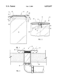
FIG. 3, a view of the cover of FIG. 1. protecting a standpipe and with a cement floor, shown in section, around the standpipe and cover.
Referring now to the drawings:
In the illustrated preferred embodiment of the invention the cover, shown generally at 10, comprises a flexible tube 12 with a pair of draw strings 14 and 16 at one end. Tube 12 is made of a suitable plastic sheeting material having a thickness sufficient to allow it to be subjected to the wear of curing concrete surrounding the tube and a standpipe covered by the tube. With a tube made of polyethylene plastic a thickness of at least five millimeters has been found suitable. Other materials can be used, and the thickness of the tubes made from such other materials may be different from that of a tube made from polyethylene plastic material.
One end 18 of the tube is turned back at 20 to be sealed fully around the tube at 22 and to form an encircling sleeve 24. Sleeve 24 is notched at opposite ends 26 and 28 and draw strings 14 and 16 are inserted, with the ends 34 and 36 of string 16 being inserted from notch 26, through opposite sides of the sleeve 24, to emerge at the notch 28 and with the ends 38 and 40 of string 14 being inserted from notch 28, through opposite sides of the sleeve 24, to emerge at the notch 26. The ends 34 and 36 of draw string 16 are tied together, and the ends 38 and 40 of draw string 14 are tied together to keep the draw strings from being pulled from the sleeve 24.
The notches 26 and 28 allow the end 18 of tube 12 to be turned down after the tube 12 has been placed over a standpipe 48 and been closed at the end 18 by pulling on the ends of both draw strings 14 and 16 and then released after surrounding concrete 50, FIG. 3, has been poured and set up. Turning the end 18 of tube 12 typically exposes a threaded end 52 of the standpipe such that the threads on the end of the standpipe can receive additional plumbing structures.
Although a preferred embodiment of my invention has been herein disclosed it is to be understood that the disclosure is by way of example and that variations are possible without departing from the subject matter coming within the scope of the following claims, which subject matter I regard as my invention.
Claims (3)
1. A cover for standpipes comprising
a plastic tube having one open end and an opposite open end with a sleeve formed therearound, said tube being made of sheet plastic having a thickness and strength to withstand friction between a standpipe on which the tube is installed and concrete poured around the standpipe; and
at least one draw string passing through and exiting said sleeve.
2. A cover for standpipes as in claim 1, wherein the tube is brightly colored.
3. A cover for standpipes as in claim 2, wherein
the sleeve is notched at opposite ends thereof and includes a first draw string having ends extending from one notch through the sleeve to the other notch and a second draw string having ends extending from the other notch through the sleeve to the one notch, whereby said sleeve is foldable at the notches when the drawstrings are released.
Priority Applications (1)
| Application Number | Priority Date | Filing Date | Title |
|---|---|---|---|
| US09/292,320 US6032697A (en) | 1999-04-15 | 1999-04-15 | Cover for standpipes |
Applications Claiming Priority (1)
| Application Number | Priority Date | Filing Date | Title |
|---|---|---|---|
| US09/292,320 US6032697A (en) | 1999-04-15 | 1999-04-15 | Cover for standpipes |
Publications (1)
| Publication Number | Publication Date |
|---|---|
| US6032697A true US6032697A (en) | 2000-03-07 |
Family
ID=23124157
Family Applications (1)
| Application Number | Title | Priority Date | Filing Date |
|---|---|---|---|
| US09/292,320 Expired - Fee Related US6032697A (en) | 1999-04-15 | 1999-04-15 | Cover for standpipes |
Country Status (1)
| Country | Link |
|---|---|
| US (1) | US6032697A (en) |
Cited By (11)
| Publication number | Priority date | Publication date | Assignee | Title |
|---|---|---|---|---|
| US6332478B1 (en) * | 2000-06-29 | 2001-12-25 | General Electric Company | Reusable pipe flange covers |
| US6386238B1 (en) * | 2001-08-09 | 2002-05-14 | General Electric Company | Methods and apparatus for detangling coiled hoses and springs |
| US20040065335A1 (en) * | 2000-02-18 | 2004-04-08 | Huber Petra Kressierer | Respiratory gas hose system for supplying a respiratory gas |
| US20050011566A1 (en) * | 2003-07-14 | 2005-01-20 | Blake Schritter | Hydraulic pipe sleeve |
| US20050051225A1 (en) * | 2003-09-04 | 2005-03-10 | Thomas Monden | Extension for a passageway |
| US20170050619A1 (en) * | 2015-08-21 | 2017-02-23 | Randy Greene | Recreational vehicle service compartment sealing shroud |
| US10047877B2 (en) | 2015-06-22 | 2018-08-14 | Spencer J Lambeth | Utility line shroud |
| US10571046B1 (en) | 2019-01-17 | 2020-02-25 | Spencer J Lambeth | Utility line shroud |
| US10605395B1 (en) * | 2018-10-02 | 2020-03-31 | Robert Dallas Green | Collapsible plug for downspouts |
| USD903837S1 (en) * | 2018-04-24 | 2020-12-01 | Kevin Hughes | Septic system pipe cover |
| US20210215290A1 (en) * | 2020-01-15 | 2021-07-15 | Electric Cleaner Company, Inc. | Systems and Methods Related to Conduit Insulation |
Citations (9)
| Publication number | Priority date | Publication date | Assignee | Title |
|---|---|---|---|---|
| US2942625A (en) * | 1956-02-27 | 1960-06-28 | Frank E Costanzo | Pipe-end protectors |
| US3587654A (en) * | 1968-11-12 | 1971-06-28 | Superior Valve | Quick-removable seal caps for fittings and the like |
| US3800486A (en) * | 1972-07-24 | 1974-04-02 | Harvey W Co | Pipe spacer |
| US4158407A (en) * | 1977-10-17 | 1979-06-19 | Rest Frederick G | Journal guard |
| US4168726A (en) * | 1977-05-25 | 1979-09-25 | Scott Insulation Company Inc. | Thermal boot apparatus |
| US4372585A (en) * | 1981-02-02 | 1983-02-08 | Victor Evora | Sleeve protector for venting pipes |
| US5687773A (en) * | 1996-06-03 | 1997-11-18 | Ryan; Stephen M. | Exhaust pipe cover and method of covering an exhaust pipe |
| US5915899A (en) * | 1996-12-05 | 1999-06-29 | Dennis; John G. | End restraint for securing plural elongated items |
| US5921282A (en) * | 1997-04-16 | 1999-07-13 | Tci Products | Protective cover for plumbing fixtures |
-
1999
- 1999-04-15 US US09/292,320 patent/US6032697A/en not_active Expired - Fee Related
Patent Citations (9)
| Publication number | Priority date | Publication date | Assignee | Title |
|---|---|---|---|---|
| US2942625A (en) * | 1956-02-27 | 1960-06-28 | Frank E Costanzo | Pipe-end protectors |
| US3587654A (en) * | 1968-11-12 | 1971-06-28 | Superior Valve | Quick-removable seal caps for fittings and the like |
| US3800486A (en) * | 1972-07-24 | 1974-04-02 | Harvey W Co | Pipe spacer |
| US4168726A (en) * | 1977-05-25 | 1979-09-25 | Scott Insulation Company Inc. | Thermal boot apparatus |
| US4158407A (en) * | 1977-10-17 | 1979-06-19 | Rest Frederick G | Journal guard |
| US4372585A (en) * | 1981-02-02 | 1983-02-08 | Victor Evora | Sleeve protector for venting pipes |
| US5687773A (en) * | 1996-06-03 | 1997-11-18 | Ryan; Stephen M. | Exhaust pipe cover and method of covering an exhaust pipe |
| US5915899A (en) * | 1996-12-05 | 1999-06-29 | Dennis; John G. | End restraint for securing plural elongated items |
| US5921282A (en) * | 1997-04-16 | 1999-07-13 | Tci Products | Protective cover for plumbing fixtures |
Cited By (14)
| Publication number | Priority date | Publication date | Assignee | Title |
|---|---|---|---|---|
| US7086422B2 (en) * | 2000-02-18 | 2006-08-08 | Map Medizin-Technologie Gmbh | Respiratory gas hose system for supplying a respiratory gas |
| US20040065335A1 (en) * | 2000-02-18 | 2004-04-08 | Huber Petra Kressierer | Respiratory gas hose system for supplying a respiratory gas |
| US7637288B2 (en) | 2000-02-18 | 2009-12-29 | Map Medizin-Technologie Gmbh | Respiratory gas hose system for supplying a respiratory gas |
| US6332478B1 (en) * | 2000-06-29 | 2001-12-25 | General Electric Company | Reusable pipe flange covers |
| US6386238B1 (en) * | 2001-08-09 | 2002-05-14 | General Electric Company | Methods and apparatus for detangling coiled hoses and springs |
| US20050011566A1 (en) * | 2003-07-14 | 2005-01-20 | Blake Schritter | Hydraulic pipe sleeve |
| US20050051225A1 (en) * | 2003-09-04 | 2005-03-10 | Thomas Monden | Extension for a passageway |
| US10047877B2 (en) | 2015-06-22 | 2018-08-14 | Spencer J Lambeth | Utility line shroud |
| US20170050619A1 (en) * | 2015-08-21 | 2017-02-23 | Randy Greene | Recreational vehicle service compartment sealing shroud |
| US9994194B2 (en) * | 2015-08-21 | 2018-06-12 | Randy Greene | Recreational vehicle service compartment sealing shroud |
| USD903837S1 (en) * | 2018-04-24 | 2020-12-01 | Kevin Hughes | Septic system pipe cover |
| US10605395B1 (en) * | 2018-10-02 | 2020-03-31 | Robert Dallas Green | Collapsible plug for downspouts |
| US10571046B1 (en) | 2019-01-17 | 2020-02-25 | Spencer J Lambeth | Utility line shroud |
| US20210215290A1 (en) * | 2020-01-15 | 2021-07-15 | Electric Cleaner Company, Inc. | Systems and Methods Related to Conduit Insulation |
Similar Documents
| Publication | Publication Date | Title |
|---|---|---|
| US6032697A (en) | Cover for standpipes | |
| US6595242B2 (en) | Tear-out coupling with embedded wire | |
| US6640825B2 (en) | Leak and spill containment bag for transformer valves | |
| FR2659998A1 (en) | Support for floor outlet connection piece | |
| US7472912B2 (en) | Tear-out coupling and water line | |
| US7089642B2 (en) | Device used to protect/repair debris chute | |
| GB0218108D0 (en) | Fitting for composite pipe | |
| JP2007291658A (en) | Piping device for temporary toilet | |
| ES2187986T3 (en) | SECURITY VALVE. | |
| US20170051494A1 (en) | Devices and methods for cross bore safeguard during sewer systems cleanouts | |
| US20090090078A1 (en) | Combination pipe test cap and concrete sleeve | |
| FI90589B (en) | Pipes for re-lining underground pipelines | |
| US20190211961A1 (en) | Hose liner | |
| KR100490026B1 (en) | Connecting device for synthetic conduit and sewer pipes in civil engineering works such as construction and road | |
| JP2005256416A (en) | Method for joining jacket structure and pile and joining member | |
| US6976499B2 (en) | Tear-out coupling with cantilevered pull tab | |
| KR200341353Y1 (en) | Sewer connecting structure of polyethylene using clip | |
| AU769829B2 (en) | Improvements to methods for protecting pipes passing through concrete | |
| WO2012107768A1 (en) | A stopper | |
| JP2007217983A (en) | Apparatus for slipping and removing snow | |
| FR2794157A1 (en) | ACCORDION FOLDING COVER DEVICE | |
| US9759362B2 (en) | Coupler assembly kit and methods of use | |
| KR950003722Y1 (en) | Safety device for opening of slabs | |
| US20020088499A1 (en) | Tear-out coupling | |
| EP2754937B1 (en) | Closure and method for its use |
Legal Events
| Date | Code | Title | Description |
|---|---|---|---|
| REMI | Maintenance fee reminder mailed | ||
| LAPS | Lapse for failure to pay maintenance fees | ||
| FP | Lapsed due to failure to pay maintenance fee |
Effective date: 20040307 |
|
| STCH | Information on status: patent discontinuation |
Free format text: PATENT EXPIRED DUE TO NONPAYMENT OF MAINTENANCE FEES UNDER 37 CFR 1.362 |